CN114502084A - Compressible non-fibrous adjunct - Google Patents
Compressible non-fibrous adjunctDownload PDFInfo
- Publication number
- CN114502084A CN114502084ACN202080064833.8ACN202080064833ACN114502084ACN 114502084 ACN114502084 ACN 114502084ACN 202080064833 ACN202080064833 ACN 202080064833ACN 114502084 ACN114502084 ACN 114502084A
- Authority
- CN
- China
- Prior art keywords
- appendage
- tissue
- appendages
- cartridge
- cells
- Prior art date
- Legal status (The legal status is an assumption and is not a legal conclusion. Google has not performed a legal analysis and makes no representation as to the accuracy of the status listed.)
- Pending
Links
Images


Landscapes
- Surgical Instruments (AREA)
- Materials For Medical Uses (AREA)
Abstract
Translated fromChinese
Description
Translated fromChinese相关申请的交叉引用CROSS-REFERENCE TO RELATED APPLICATIONS
本申请要求于2019年9月16日提交的名称为“Bioabsorbable Resin forAdditive Manufacturing”的美国临时专利申请62/900,708、于2019年10月10日提交的名称为“Bioabsorbable Resin for Additive Manufacturing”的美国临时专利申请62/913,227和于2020年7月20日提交的名称为“Compressible3D Printed Scaffolds”的美国临时专利申请63/053,863的优先权,这些专利的公开内容全文以引用方式并入本文。This application claims U.S. Provisional Patent Application 62/900,708, filed September 16, 2019, entitled "Bioabsorbable Resin for Additive Manufacturing," and U.S. Provisional Patent Application 62/900,708, filed October 10, 2019, entitled "Bioabsorbable Resin for Additive Manufacturing." Priority to patent application 62/913,227 and US Provisional Patent Application 63/053,863, filed July 20, 2020, entitled "Compressible 3D Printed Scaffolds," the disclosures of which are incorporated herein by reference in their entirety.
技术领域technical field
提供了可压缩的非纤维附属物以及制造和使用该可压缩的非纤维附属物的方法。Compressible non-fibrous appendages and methods of making and using the compressible non-fibrous appendages are provided.
背景技术Background technique
外科缝合器用于外科手术中,以闭合在特定手术中所涉及的组织、血管、导管、分流管、或者其他物体或身体部分中的开口。这些开口可为天然存在的,诸如血管或类似于胃的内部器官中的通路,或者它们可为在外科手术期间由外科医生形成的,诸如通过穿刺组织或血管以形成旁路或吻合部或通过在缝合手术期间切割组织。Surgical staplers are used in surgical procedures to close openings in tissue, blood vessels, catheters, shunts, or other objects or body parts involved in a particular procedure. These openings may be naturally occurring, such as passages in blood vessels or internal organs like the stomach, or they may be created by the surgeon during surgical procedures, such as by puncturing tissue or blood vessels to create bypasses or anastomosis or through Tissue is cut during the suturing procedure.
一些外科缝合器需要外科医生为正被缝合的组织选择具有适当钉高度的适当钉。例如,外科医生可选择用于厚组织的长钉和用于薄组织的短钉。然而,在一些情况下,被缝合的组织不具有一致的厚度,因此钉不能在每个钉部位处实现期望的击发构型。因此,不能在所有缝合部位处或附近都形成期望的密封,从而允许血液、空气、胃肠液和其他流体通过未密封部位渗出。Some surgical staplers require the surgeon to select the appropriate staples with the appropriate staple height for the tissue being stapled. For example, a surgeon may choose long staples for thick tissue and short staples for thin tissue. However, in some cases, the tissue being stapled does not have a consistent thickness, so the staples cannot achieve the desired firing configuration at each staple site. As a result, the desired seal cannot be formed at or near all suture sites, allowing blood, air, gastrointestinal fluids, and other fluids to seep through the unsealed site.
另外,作为凹陷通道的钉与可结合类似于缝合的手术来植入的其他物体和材料一样,通常缺乏它们所植入的组织的一些特性。例如,钉以及其他物体和材料可缺乏它们所植入的组织的天然柔韧性,因此不能承受植入部位处的组织内压力不同。这会导致在缝合部位处或附近的不期望的组织撕裂,并因此导致渗漏。In addition, staples that are recessed channels, like other objects and materials that can be implanted in conjunction with suturing-like procedures, typically lack some of the properties of the tissue in which they are implanted. For example, staples and other objects and materials may lack the natural flexibility of the tissue in which they are implanted and therefore cannot withstand varying intra-tissue pressures at the implant site. This can lead to undesired tearing of tissue at or near the suture site, and thus to leakage.
因此,仍然需要用于解决外科缝合器的当前问题的改进的器械和方法。Accordingly, there remains a need for improved instruments and methods for addressing current problems with surgical staplers.
发明内容SUMMARY OF THE INVENTION
还提供了与外科缝合器一起使用的缝合组件。在一个示例性实施方案中,缝合组件包括具有设置在其中的多个钉的仓和非纤维附属物,该多个钉被构造成能够被部署到组织中,并且该非纤维附属物由至少一种熔融的可生物吸收聚合物形成,并且被构造成能够被可释放地保持在仓上,使得该附属物可通过仓中的该多个钉附接到组织,该附属物由多个重复互连的单元格形成,在该多个单元格之间形成有中空管状互连件,每个单元格具有限定内部体积的内表面,其中中空管状互连件允许单元格的内部体积流体连通,以促进附属物内加速的组织向内生长。Suture assemblies for use with surgical staplers are also provided. In an exemplary embodiment, a suturing assembly includes a cartridge having a plurality of staples disposed therein and a non-fibrous appendage configured to be deployable into tissue, and the non-fibrous appendage is comprised of at least one is formed of a molten bioabsorbable polymer and is configured to be releasably retained on the cartridge such that the appendage can be attached to tissue by the plurality of staples in the cartridge, the appendage being formed by a plurality of repeating interactions. Connected cells are formed with hollow tubular interconnects formed between the plurality of cells, each cell having an inner surface defining an interior volume, wherein the hollow tubular interconnects allow the interior volumes of the cells to be in fluid communication to Promotes accelerated tissue ingrowth within appendages.
在一些实施方案中,每个中空管状互连件可限定具有直径为100微米至3500微米的开口。In some embodiments, each hollow tubular interconnect can define an opening having a diameter of 100 microns to 3500 microns.
该多个重复单元格可具有多种构型。例如,在一些实施方案中,该多个重复单元格可包括三重周期性最小表面结构。在其他实施方案中,该多个重复单元格可包括Schwarz-P结构。在某些实施方案中,该多个重复单元格可包括调整的Schwarz-P结构。在其他实施方案中,在附属物处于组织部署状态时,中空互连件的至少一部分可至少部分地保持单元格的内部体积的至少一部分之间的流体连通,从而促进整个附属物中的细胞移动性。在某些实施方案中,每个单元格可具有0.1mm至0.3mm的壁厚。在其他实施方案中,每个单元格的表面与体积比可以是7至20。The plurality of repeating cells can have various configurations. For example, in some embodiments, the plurality of repeating cells can include a triple periodic minimal surface structure. In other embodiments, the plurality of repeating cells can comprise a Schwarz-P structure. In certain embodiments, the plurality of repeating cells can comprise an adjusted Schwarz-P structure. In other embodiments, at least a portion of the hollow interconnect can at least partially maintain fluid communication between at least a portion of the interior volume of the cells when the appendage is in a tissue-deployed state, thereby facilitating cell movement throughout the appendage sex. In certain embodiments, each cell may have a wall thickness of 0.1 mm to 0.3 mm. In other embodiments, the surface to volume ratio of each cell may be 7 to 20.
在一些实施方案中,该附属物在处于30kPa至90kPa范围内的施加应力下时可被构造成能够经历0.1至0.9范围内的应变。在某些实施方案中,该应变可处于0.1至0.7的范围内。In some embodiments, the appendage may be configured to experience a strain in the range of 0.1 to 0.9 when under an applied stress in the range of 30 kPa to 90 kPa. In certain embodiments, the strain may be in the range of 0.1 to 0.7.
在另一示例性实施方案中,缝合组件包括具有设置在其中的多个钉的仓和非纤维附属物,该多个钉被构造成能够被部署到组织中,并且该非纤维附属物由至少一种熔融的可生物吸收聚合物形成,并且被构造成能够被可释放地保持在仓上,使得该附属物可通过该仓中的该多个钉附接到组织,该附属物由互连的多个重复的中空单元格形成,使得在附属物单元格之间形成内腔,从而在附属物单元格之间产生通道,使得在所述附属物内存在通道的连续网络以允许一种或多种流体在附属物处于组织部署状态时进入和转移到整体该附属物。In another exemplary embodiment, a suturing assembly includes a cartridge having a plurality of staples disposed therein and a non-fibrous appendage, the plurality of staples being configured to be deployable into tissue, and the non-fibrous appendage consisting of at least A molten bioabsorbable polymer is formed and is configured to be releasably retained on a cartridge such that the appendages can be attached to tissue by the plurality of staples in the cartridge, the appendages being interconnected by Multiple repeating hollow cells are formed such that lumens are formed between the appendage cells, thereby creating channels between the appendage cells, such that a continuous network of channels exists within the appendages to allow for one or Various fluids enter and transfer to the entire appendage when the appendage is in a tissue-deployed state.
在一些实施方案中,每个内腔可具有100微米至3500微米的直径。In some embodiments, each lumen can have a diameter of 100 microns to 3500 microns.
该多个重复单元格可具有多种构型。例如,在一些实施方案中,该多个重复单元格可包括三重周期性最小表面结构。在其他实施方案中,该多个重复单元格可包括Schwarz-P结构。在某些实施方案中,每个单元格可具有0.1mm至0.3mm的壁厚。在其他实施方案中,每个单元格的表面与体积比可以是7至20。The plurality of repeating cells can have various configurations. For example, in some embodiments, the plurality of repeating cells can include a triple periodic minimal surface structure. In other embodiments, the plurality of repeating cells can comprise a Schwarz-P structure. In certain embodiments, each cell may have a wall thickness of 0.1 mm to 0.3 mm. In other embodiments, the surface to volume ratio of each cell may be 7 to 20.
在一些实施方案中,内腔的至少一部分可被构造成能够在附属物处于组织部署状态时至少部分地维持通道,从而促进整个附属物中的细胞移动性。In some embodiments, at least a portion of the lumen can be configured to at least partially maintain the channel when the appendage is in a tissue-deployed state, thereby promoting cell mobility throughout the appendage.
附图说明Description of drawings
通过以下结合附图所作的详细描述,将更充分地理解本发明,在附图中:The present invention will be more fully understood from the following detailed description in conjunction with the accompanying drawings, in which:
图1为常规外科缝合和切断器械的一个示例性实施方案的透视图;1 is a perspective view of an exemplary embodiment of a conventional surgical stapling and severing instrument;
图2A为与图1的外科缝合和切断器械一起使用的钉仓的顶视图;2A is a top view of a staple cartridge for use with the surgical stapling and severing instrument of FIG. 1;
图2B为图2A的钉仓的侧视图;Figure 2B is a side view of the staple cartridge of Figure 2A;
图2C为图2A的钉仓的组织接触表面的一部分的透视图;Figure 2C is a perspective view of a portion of the tissue contacting surface of the staple cartridge of Figure 2A;
图3为可设置在图4的外科仓组件的钉仓内处于未击发(预部署)构型的钉的侧视图;3 is a side view of staples that may be disposed within the staple cartridge of the surgical cartridge assembly of FIG. 4 in an unfired (pre-deployed) configuration;
图4为图1的外科缝合和切断器械的刀和击发杆(“E形梁”)的透视图;Figure 4 is a perspective view of the knife and firing rod ("E-beam") of the surgical stapling and severing instrument of Figure 1;
图5为图1的外科缝合和切断器械的钉仓的楔形滑动件的透视图;5 is a perspective view of a wedge slide of the staple cartridge of the surgical stapling and severing instrument of FIG. 1;
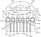
图6A为具有附接到钉仓的顶表面或平台表面的可压缩非纤维附属物的外科仓组件的示例性实施方案的纵向剖面图;6A is a longitudinal cross-sectional view of an exemplary embodiment of a surgical cartridge assembly having compressible non-fibrous appendages attached to a top or platform surface of the staple cartridge;
图6B为外科端部执行器的纵向剖面图,该外科端部执行器具有可枢转地联接到细长钉通道的砧座和图6A的设置在细长钉通道内并且联接到该细长钉通道的外科仓组件,该图示出了处于砧座与附属物之间没有任何组织的闭合位置的砧座;6B is a longitudinal cross-sectional view of a surgical end effector having an anvil pivotally coupled to an elongated staple channel and of FIG. 6A disposed within the elongated staple channel and coupled to the elongated staple channel. a surgical cartridge assembly for a staple channel, the figure showing the anvil in a closed position without any tissue between the anvil and the appendage;
图7为示出图6A至图6B的处于组织部署条件下的附属物的部分示意图;7 is a partial schematic diagram illustrating the appendage of FIGS. 6A-6B in a tissue-deployed condition;
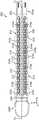
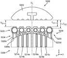
图8A为是可压缩非纤维附属物的另一示例性实施方案的透视图;8A is a perspective view of another exemplary embodiment of a compressible non-fibrous appendage;
图8B为图8A的附属物的侧视图;Figure 8B is a side view of the appendage of Figure 8A;
图8C为图8A的附属物的顶视图;Figure 8C is a top view of the appendage of Figure 8A;
图8D为图8C的附属物在线8D-8D处截取的剖面图;8D is a cross-sectional view of the appendage of FIG. 8C taken at
图8E为图8C的附属物在线8E-8E处截取的剖面图;8E is a cross-sectional view of the appendage of FIG. 8C taken at
图8F为图8C的附属物的一部分在8F处截取的放大图;Figure 8F is an enlarged view of a portion of the appendage of Figure 8C taken at 8F;
图8G为示出图8A的处于组织部署状态的附属物的局部示意图;8G is a partial schematic diagram illustrating the appendage of FIG. 8A in a tissue-deployed state;
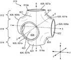
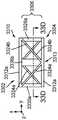
图9A为图8A的附属物的单个单元格的侧视图;Figure 9A is a side view of a single cell of the appendage of Figure 8A;
图9B为图9A的单个单元格的透视图;Figure 9B is a perspective view of the single cell of Figure 9A;
图10A为处于预压缩状态的示例性单元格的示意图;10A is a schematic diagram of an exemplary cell in a pre-compressed state;
图10B为图10A的处于第一压缩状态的单元格的示意图;FIG. 10B is a schematic diagram of the cell of FIG. 10A in a first compressed state;
图10C为图10A的处于第二压缩状态的单元格的示意图;FIG. 10C is a schematic diagram of the cell of FIG. 10A in a second compressed state;
图10D为图10A的处于致密状态的单元格的示意图;10D is a schematic diagram of the cell of FIG. 10A in a densified state;
图11为图10A至图10D的单元格的状态与所得可压缩非纤维附属物的应力-应变曲线之间的关系的示意图;11 is a schematic diagram of the relationship between the state of the cells of FIGS. 10A-10D and the stress-strain curves of the resulting compressible non-fibrous appendages;
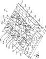
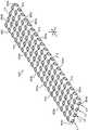
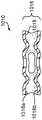
图12A为由调整的Schwarz-P结构的实施方案的重复单元格形成的可压缩非纤维附属物的示例性实施方案的顶视图;12A is a top view of an exemplary embodiment of a compressible non-fibrous appendage formed from repeating cells of an embodiment of the adjusted Schwarz-P structure;
图12B为由调整的Schwarz-P结构的另一实施方案的重复单元格形成的可压缩非纤维附属物的示例性实施方案的顶视图;12B is a top view of an exemplary embodiment of a compressible non-fibrous appendage formed from repeating cells of another embodiment of the tuned Schwarz-P structure;
图12C为由调整的Schwarz-P结构的另一实施方案的重复单元格形成的可压缩非纤维附属物的示例性实施方案的顶视图;Figure 12C is a top view of an exemplary embodiment of a compressible non-fibrous appendage formed from repeating cells of another embodiment of the tuned Schwarz-P structure;
图12D为由调整的Schwarz-P结构的另一实施方案的重复单元格形成的可压缩非纤维附属物的示例性实施方案的顶视图;12D is a top view of an exemplary embodiment of a compressible non-fibrous appendage formed from repeating cells of another embodiment of the tuned Schwarz-P structure;
图13A为单个单元格的另一示例性实施方案的透视图;13A is a perspective view of another exemplary embodiment of a single cell;
图13B为由图13A的重复单元格形成的可压缩非纤维附属物的示例性实施方案的俯视图;Figure 13B is a top view of an exemplary embodiment of a compressible non-fibrous appendage formed from the repeating cells of Figure 13A;
图14A为单个单元格的另一示例性实施方案的透视图;Figure 14A is a perspective view of another exemplary embodiment of a single cell;
图14B为由图14A的重复单元格形成的可压缩非纤维附属物的示例性实施方案的俯视图;Figure 14B is a top view of an exemplary embodiment of a compressible non-fibrous appendage formed from the repeating cells of Figure 14A;
图15A为单个单元格的另一示例性实施方案的透视图;Figure 15A is a perspective view of another exemplary embodiment of a single cell;
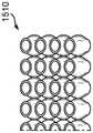
图15B为由图15A的重复单元格形成的可压缩非纤维附属物的示例性实施方案的俯视图;Figure 15B is a top view of an exemplary embodiment of a compressible non-fibrous appendage formed from the repeating cells of Figure 15A;
图16A为单个单元格的另一示例性实施方案的透视图;Figure 16A is a perspective view of another exemplary embodiment of a single cell;
图16B为由图16A的重复单元格形成的可压缩非纤维附属物的示例性实施方案的俯视图;Figure 16B is a top view of an exemplary embodiment of a compressible non-fibrous appendage formed from the repeating cells of Figure 16A;
图17A为可压缩非纤维附属物的另一示例性实施方案的透视图;17A is a perspective view of another exemplary embodiment of a compressible non-fibrous appendage;
图17B为图17A的附属物在线17B-17B处截取的剖面图;17B is a cross-sectional view of the appendage of FIG. 17A taken at
图17C为图17A的附属物在线17C-17C处截取的剖面图;17C is a cross-sectional view of the appendage of FIG. 17A taken at
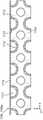
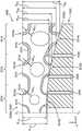
图18为设置在钉仓上的可压缩非纤维附属物的另一示例性实施方案的透视图;18 is a perspective view of another exemplary embodiment of a compressible non-fibrous appendage disposed on a staple cartridge;
图19A为具有通道附接件的可压缩非纤维附属物的另一示例性实施方案的透视图;19A is a perspective view of another exemplary embodiment of a compressible non-fibrous appendage with channel attachments;
图19B为图19A的附属物在线19B-19B处截取的剖面图;Figure 19B is a cross-sectional view of the appendage of Figure 19A taken at
图20为具有通道附接件的可压缩非纤维附属物的另一示例性实施方案的局部透视图;20 is a partial perspective view of another exemplary embodiment of a compressible non-fibrous appendage with channel attachments;
图21为具有通道附接件的可压缩非纤维附属物的另一示例性实施方案的局部透视图;21 is a partial perspective view of another exemplary embodiment of a compressible non-fibrous appendage with channel attachments;
图22A为缝合组件的示例性实施方案的局部分解透视图,该缝合组件具有可释放地保持在钉仓上的可压缩非纤维附属物,每个可压缩非纤维附属物具有对应的边缘附接特征部;22A is a partially exploded perspective view of an exemplary embodiment of a suturing assembly having compressible non-fibrous appendages releasably retained on a staple cartridge, each compressible non-fibrous appendage having a corresponding edge attachment feature;
图22B为缝合组件的一部分在线22B至22B处截取的放大剖面图,示出了在接合之前的两个边缘附接特征部;22B is an enlarged cross-sectional view of a portion of the suture assembly taken at
图22C为图22B的缝合组件的一部分的剖面图,示出了接合的两个边缘附接特征部;Figure 22C is a cross-sectional view of a portion of the suture assembly of Figure 22B showing two edge attachment features joined;
图23A为缝合组件的另一示例性实施方案的透视图,该缝合组件具有可释放地保持在钉仓上的可压缩非纤维附属物,每个可压缩非纤维附属物具有对应的边缘附接特征部,该图示出了接合的边缘附接特征部;23A is a perspective view of another exemplary embodiment of a suturing assembly having compressible non-fibrous appendages releasably retained on a staple cartridge, each compressible non-fibrous appendage having a corresponding edge attachment a feature, the figure showing the engaged edge attachment feature;
图23B为图23B的缝合组件的一部分的放大图;Figure 23B is an enlarged view of a portion of the suturing assembly of Figure 23B;
图24为具有端部附接特征部的钉仓的另一示例性实施方案的透视图;24 is a perspective view of another exemplary embodiment of a staple cartridge having end attachment features;
图25为具有端部附接特征部的钉仓的另一示例性实施方案的透视图;25 is a perspective view of another exemplary embodiment of a staple cartridge having end attachment features;
图26A为具有钉仓和可压缩非纤维附属物的缝合组件的另一示例性实施方案的分解图,其中附接特征部可释放地保持在可压缩非纤维附属物上;26A is an exploded view of another exemplary embodiment of a suturing assembly having a staple cartridge and compressible non-fibrous appendages with attachment features releasably retained on the compressible non-fibrous appendages;
图26B为图26A的缝合组件在线26B-26B处截取的剖面图;26B is a cross-sectional view of the suture assembly of FIG. 26A taken at
图26C为图26A的缝合组件在线26C-26C处截取的剖面图;Figure 26C is a cross-sectional view of the suture assembly of Figure 26A taken at
图27为缝合组件的另一示例性实施方案的局部剖面图,该缝合组件具有可释放地保持在钉仓上的可压缩非纤维附属物;27 is a partial cross-sectional view of another exemplary embodiment of a suturing assembly having compressible non-fibrous appendages releasably retained on a staple cartridge;
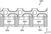
图28A为缝合组件的另一示例性实施方案的局部剖面图,该缝合组件具有可释放地保持在钉仓上的可压缩非纤维附属物;28A is a partial cross-sectional view of another exemplary embodiment of a suturing assembly having compressible non-fibrous appendages releasably retained on a staple cartridge;
图28B为示出图28A的处于组织部署条件下的附属物的局部示意图;FIG. 28B is a partial schematic diagram illustrating the appendage of FIG. 28A in a tissue-deployed condition;
图29为缝合组件的另一示例性实施方案的局部剖面图,该缝合组件具有可释放地保持在钉仓上的可压缩非纤维附属物;29 is a partial cross-sectional view of another exemplary embodiment of a suturing assembly having compressible non-fibrous appendages releasably retained on a staple cartridge;
图30A为可压缩非纤维附属物的另一示例性实施方案的透视图;30A is a perspective view of another exemplary embodiment of a compressible non-fibrous appendage;
图30B为图30A的附属物的前平面图;Figure 30B is a front plan view of the appendage of Figure 30A;
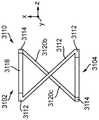
图31A为可压缩非纤维附属物的一个实施方案的透视图;Figure 31A is a perspective view of one embodiment of a compressible non-fibrous appendage;
图31B为图31A的附属物的单个单元格的透视图;Figure 31B is a perspective view of a single cell of the appendage of Figure 31A;
图31C为图31B的单元格的侧视图;Figure 31C is a side view of the cell of Figure 31B;
图31D为图31B至图31C的单元格的替代侧视图;Figure 31D is an alternate side view of the cell of Figures 31B-31C;
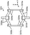
图32A为可压缩非纤维附属物的另一示例性实施方案的透视图;32A is a perspective view of another exemplary embodiment of a compressible non-fibrous appendage;
图32B为图32A的附属物的单个单元格的透视图;Figure 32B is a perspective view of a single cell of the appendage of Figure 32A;
图32C为图32B的单元格的侧视图;Figure 32C is a side view of the cell of Figure 32B;
图32D为图32B至图32C的单元格沿着图32C的线32D-32D截取处的截面顶视图;Figure 32D is a cross-sectional top view of the cell of Figures 32B-32C taken along
图33A为可压缩非纤维附属物的另一示例性实施方案的透视图;33A is a perspective view of another exemplary embodiment of a compressible non-fibrous appendage;
图33B为图33A的附属物的单个单元格的透视图;Figure 33B is a perspective view of a single cell of the appendage of Figure 33A;
图33C为图33B的单元格的侧视图;Figure 33C is a side view of the cell of Figure 33B;
图33D为图33B至图33C的单元格沿着图33C的线33D-33D截取处的截面顶视图;Figure 33D is a cross-sectional top view of the cell of Figures 33B-33C taken along
图33E为图33B至图33C的单元格的替代侧视图;Figure 33E is an alternate side view of the cell of Figures 33B-33C;
图34A为可压缩非纤维附属物的另一示例性实施方案的透视图;34A is a perspective view of another exemplary embodiment of a compressible non-fibrous appendage;
图34B为图34A的附属物的单个单元格的透视图;Figure 34B is a perspective view of a single cell of the appendage of Figure 34A;
图34C为图34B的单元格的侧视图;Figure 34C is a side view of the cell of Figure 34B;
图34D为图34B至图34C的单元格的顶视图;Figure 34D is a top view of the cell of Figures 34B-34C;
图34E为图34B至图34C的单元格的替代侧视图;Figure 34E is an alternate side view of the cell of Figures 34B-34C;
图35为单元格的另一示例性实施方案的透视图;Figure 35 is a perspective view of another exemplary embodiment of a cell;
图36为单元格的另一示例性实施方案的透视图;Figure 36 is a perspective view of another exemplary embodiment of a cell;
图37A为具有钉仓和可压缩非纤维附属物的缝合组件的另一示例性实施方案的局部分解透视图;37A is a partially exploded perspective view of another exemplary embodiment of a suturing assembly having a staple cartridge and compressible non-fibrous appendages;
图37B为图37A的缝合组件的一部分在线37B-37B处截取的剖面图;37B is a cross-sectional view of a portion of the suture assembly of FIG. 37A taken at
图38A为图37B的缝合组件的一部分的示意图,示出了设置到附属物上的组织;Fig. 38A is a schematic view of a portion of the suturing assembly of Fig. 37B showing tissue disposed on an appendage;
图38B为示出图37A的处于组织部署条件下的附属物的局部示意图;Fig. 38B is a partial schematic view showing the appendage of Fig. 37A in a tissue-deployed condition;
图39A为具有钉仓和附属物的缝合组件的示例性实施方案的分解图,其中仅示出了附属物的第二外层;39A is an exploded view of an exemplary embodiment of a suturing assembly with a staple cartridge and appendages, wherein only the second outer layer of the appendages is shown;
图39B为图39A的缝合组件的前视图;Figure 39B is a front view of the suturing assembly of Figure 39A;
图40为缝合组件的另一示例性实施方案的透视图,该缝合组件具有可释放地保持在钉仓上的可压缩非纤维附属物;40 is a perspective view of another exemplary embodiment of a suturing assembly having compressible non-fibrous appendages releasably retained on a staple cartridge;
图41A为可压缩非纤维附属物的另一示例性实施方案的透视图;41A is a perspective view of another exemplary embodiment of a compressible non-fibrous appendage;
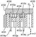
图41B为图41A的在线41B-41B处截取并且可释放地保持在钉仓上的附属物的一部分的剖面图;41B is a cross-sectional view of a portion of the appendage of FIG. 41A taken at
图41C为图41A的在线41C-41C处截取并且可释放地保持在钉仓上的附属物的一部分的剖面图;41C is a cross-sectional view of a portion of the appendage of FIG. 41A taken at
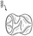
图42A为可压缩非纤维附属物的另一示例性实施方案的透视图;42A is a perspective view of another exemplary embodiment of a compressible non-fibrous appendage;
图42B为示出图42A的处于组织部署条件下的附属物的局部示意图;FIG. 42B is a partial schematic diagram illustrating the appendage of FIG. 42A in a tissue-deployed condition;
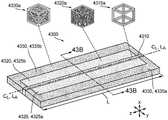
图43A为可压缩非纤维附属物的另一示例性实施方案的透视图;43A is a perspective view of another exemplary embodiment of a compressible non-fibrous appendage;
图43B为图43A的附属物在线43B-43B处截取的剖面图;Figure 43B is a cross-sectional view of the appendage of Figure 43A taken at
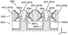
图44A为可压缩非纤维附属物的另一示例性实施方案的剖面图,仅示出了附属物的一部分被可释放地保持在钉仓上;44A is a cross-sectional view of another exemplary embodiment of a compressible non-fibrous appendage showing only a portion of the appendage being releasably retained on the staple cartridge;
图44B为示出被夹持在砧座与图44A的附属物的一部分之间的组织的局部示意图,其中钉从钉仓部分地部署通过附属物;44B is a partial schematic view showing tissue clamped between the anvil and a portion of the appendage of FIG. 44A with staples partially deployed from the staple cartridge through the appendage;
图44C为示出图44A的处于组织部署条件下的附属物的局部示意图;Figure 44C is a partial schematic diagram showing the appendage of Figure 44A in a tissue deployment condition;
图45A为缝合组件的另一示例性实施方案的局部分解透视图,该缝合组件具有可释放地保持在钉仓上的可压缩非纤维附属物;45A is a partially exploded perspective view of another exemplary embodiment of a suturing assembly having compressible non-fibrous appendages releasably retained on a staple cartridge;
图45B为图45A的缝合组件的一部分的俯视图;Figure 45B is a top view of a portion of the suture assembly of Figure 45A;
图45C为图45B的缝合组件在线45C-45C处截取的剖面图;Figure 45C is a cross-sectional view of the suture assembly of Figure 45B taken at
图46A为具有可释放地保持在钉仓上的可压缩非纤维附属物的缝合组件的一部分的另一示例性实施方案的透视图;46A is a perspective view of another exemplary embodiment of a portion of a suture assembly having compressible non-fibrous appendages releasably retained on a staple cartridge;
图46B为图46A的缝合组件的一部分的俯视图;Figure 46B is a top view of a portion of the suturing assembly of Figure 46A;
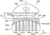
图47A为具有砧座和缝合组件的外科端部执行器的示例性实施方案的剖面前视图,该缝合组件具有可释放地保持在钉仓上的可压缩非纤维附属物,该图示出了处于砧座与缝合组件之间没有组织定位的闭合位置的外科端部执行器;47A is a cross-sectional front view of an exemplary embodiment of a surgical end effector having an anvil and a stapling assembly with compressible non-fibrous appendages releasably retained on a staple cartridge, showing a surgical end effector in a closed position with no tissue positioning between the anvil and the stapling assembly;
图47B为图47A的外科端部执行器的剖面前视图,示出了夹持在砧座与缝合组件之间并且缝合到可压缩非纤维附属物之间的组织;47B is a cutaway front view of the surgical end effector of FIG. 47A showing tissue clamped between the anvil and the stapling assembly and stapled between the compressible non-fibrous appendages;
图47C为图47A的仅缝合组件的剖面前视图;Figure 47C is a cross-sectional front view of the suture-only assembly of Figure 47A;
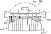
图48A为具有砧座和缝合组件的外科端部执行器的另一示例性实施方案的横截面前视图,该缝合组件具有可释放地保持在钉仓上的可压缩非纤维附属物,该图示出了处于砧座与缝合组件之间没有组织定位的闭合位置的外科端部执行器;Figure 48A is a cross-sectional front view of another exemplary embodiment of a surgical end effector having an anvil and a stapling assembly with compressible non-fibrous appendages releasably retained on a staple cartridge, the figure showing the surgical end effector in a closed position with no tissue positioning between the anvil and the stapling assembly;
图48B为图48A的外科端部执行器的横截面前视图,示出了夹持在砧座与缝合组件之间并且缝合到可压缩非纤维附属物之间的组织;Figure 48B is a cross-sectional front view of the surgical end effector of Figure 48A, showing tissue clamped between the anvil and the stapling assembly and stapled between the compressible non-fibrous appendages;
图48C为图48A的仅缝合组件的剖面前视图;Figure 48C is a cross-sectional front view of the suture-only assembly of Figure 48A;
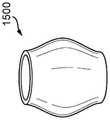
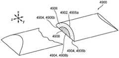
图49为可压缩非纤维附属物的另一示例性实施方案的透视图;Figure 49 is a perspective view of another exemplary embodiment of a compressible non-fibrous appendage;
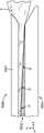
图50A为具有砧座和缝合组件的外科端部执行器的示例性实施方案的侧视图,该缝合组件具有可释放地保持在钉仓上的可压缩非纤维附属物,该图示出了处于砧座与缝合组件之间没有组织定位的闭合位置的外科端部执行器;50A is a side view of an exemplary embodiment of a surgical end effector having an anvil and a stapling assembly with compressible non-fibrous appendages releasably retained on a staple cartridge, shown in a surgical end effector in a closed position without tissue positioning between the anvil and the stapling assembly;
图50B为图50A的外科端部执行器的侧视图,示出了夹持在砧座与缝合组件之间的组织;Figure 50B is a side view of the surgical end effector of Figure 50A showing tissue clamped between the anvil and the stapling assembly;
图50C为图50A的仅缝合组件的侧视图;Figure 50C is a side view of the suture only assembly of Figure 50A;
图51A为具有砧座和缝合组件的外科端部执行器的另一示例性实施方案的横截面前视图,该缝合组件具有可释放地保持在钉仓上的可压缩非纤维附属物,该图示出了处于砧座与缝合组件之间没有组织定位的闭合位置的外科端部执行器;51A is a cross-sectional front view of another exemplary embodiment of a surgical end effector having an anvil and a stapling assembly having compressible non-fibrous appendages releasably retained on a staple cartridge, the figure showing the surgical end effector in a closed position with no tissue positioning between the anvil and the stapling assembly;
图51B为图51A的仅可压缩非纤维附属物的剖面前视图;Figure 51B is a cross-sectional front view of the compressible only non-fibrous appendage of Figure 51A;
图52A为具有砧座和缝合组件的外科端部执行器的另一示例性实施方案的横截面前视图,该缝合组件具有可释放地保持在钉仓上的可压缩非纤维附属物,该图示出了处于砧座与缝合组件之间没有组织定位的闭合位置的外科端部执行器;Figure 52A is a cross-sectional front view of another exemplary embodiment of a surgical end effector having an anvil and a stapling assembly with compressible non-fibrous appendages releasably retained on a staple cartridge, the figure showing the surgical end effector in a closed position with no tissue positioning between the anvil and the stapling assembly;
图52B为图52A的仅缝合组件的一部分的剖面前视放大图;Figure 52B is an enlarged cross-sectional front view of only a portion of the suture assembly of Figure 52A;
图53为可释放地保持在钉仓上的可压缩非纤维附属物的另一示例性实施方案的一部分的剖面图;53 is a cross-sectional view of a portion of another exemplary embodiment of a compressible non-fibrous appendage releasably retained on a staple cartridge;
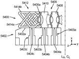
图54为可释放地保持在钉仓上的可压缩非纤维附属物的另一示例性实施方案的一部分的剖面图,仅示出了来自钉仓的三个钉排的三个钉;54 is a cross-sectional view of a portion of another exemplary embodiment of a compressible non-fibrous appendage releasably retained on a staple cartridge, showing only three staples from three staple rows of the staple cartridge;
图55为图54的附属物在三个钉中的每一个钉处的应力-应变曲线的示意图;Fig. 55 is a schematic diagram of the stress-strain curve of the appendage of Fig. 54 at each of the three pegs;
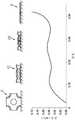
图56为示出示例9和示例10的示例性可压缩非纤维附属物(附属物1)的应力-应变曲线的图;56 is a graph showing stress-strain curves for an exemplary compressible non-fibrous appendage (Appendix 1 ) of Examples 9 and 10;
图57为示出示例9和示例10的示例性可压缩非纤维附属物(附属物2-5)的应力-应变曲线的图;并且57 is a graph showing stress-strain curves for exemplary compressible non-fibrous appendages (Appendages 2-5) of Examples 9 and 10; and
图58为示出示例11的可压缩非纤维附属物的六个示例性实施方案的应力-应变曲线的图。58 is a graph showing stress-strain curves for six exemplary embodiments of the compressible non-fibrous appendage of Example 11. FIG.
具体实施方式Detailed ways
现在将描述某些示例性实施方案,以得到对本文所公开的附属物、系统和方法的结构、功能、制造和使用的原理的全面理解。这些实施方案的一个或多个示例在附图中示出。本领域的技术人员将会理解,在本文中具体描述的和在附图中示出的附属物、系统和方法是非限制性的示例性实施方案,并且本发明的范围仅由权利要求书限定。结合一个示例性实施方案示出或描述的特征部可与其它实施方案的特征部进行组合。此类修改和变型旨在包括在本发明的范围之内。Certain exemplary embodiments will now be described in order to gain a thorough understanding of the principles of structure, function, manufacture, and use of the appendages, systems and methods disclosed herein. One or more examples of these embodiments are illustrated in the accompanying drawings. Those skilled in the art will understand that the appendices, systems and methods specifically described herein and illustrated in the accompanying drawings are non-limiting exemplary embodiments and that the scope of the present invention is limited only by the claims. Features shown or described in connection with one exemplary embodiment may be combined with features of other embodiments. Such modifications and variations are intended to be included within the scope of the present invention.
提供了外科缝合组件及其制造和使用该外科缝合组件的方法。通常,外科缝合组件可包括钉仓,该钉仓具有设置在其中的钉和被构造成能够被可释放地保持在该钉仓上的可压缩的可生物吸收的非纤维附属物。在一些实施方案中,非纤维附属物可由包括至少一种熔融可生物吸收聚合物的基质形成,并且因此该非纤维附属物可以是三维打印的。在其他实施方案中,非纤维附属物可通过任何合适的非增材制造工艺(诸如,如本领域的技术人员所理解的注塑、发泡和成型工艺)部分或完全地形成。如本文所讨论的,多种附属物可被构造成能够补偿组织特性的变化(诸如组织厚度的变化),以及/或者当将该附属物缝合到组织上时促进组织向内生长。例如,附属物可被构造成能够使得该附属物在处于约30kPa至90kPa范围内的施加应力下时经历约0.1(10%变形)至0.9(变形90%)范围内的应变。也就是说,当本文所述的附属物处于介于(和/或包括)约30kPa至90kPa之间的应力下时,例如,当该附属物处于组织部署状态时,该附属物可被构造成能够发生从约10%至90%的变形。Surgical stapling assemblies and methods of making and using the same are provided. Generally, a surgical stapling assembly may include a staple cartridge having staples disposed therein and compressible bioabsorbable non-fibrous appendages configured to be releasably retained on the staple cartridge. In some embodiments, the non-fibrous appendages can be formed from a matrix comprising at least one fused bioabsorbable polymer, and thus the non-fibrous appendages can be three-dimensionally printed. In other embodiments, the non-fibrous appendages may be partially or fully formed by any suitable non-additive manufacturing process, such as injection molding, foaming, and molding processes as understood by those skilled in the art. As discussed herein, various appendages can be configured to compensate for changes in tissue properties, such as changes in tissue thickness, and/or to promote tissue ingrowth when the appendage is sutured to tissue. For example, the appendage may be configured such that the appendage experiences a strain in the range of about 0.1 (10% deformation) to 0.9 (90% deformation) when under an applied stress in the range of about 30 kPa to 90 kPa. That is, when the appendages described herein are under stress between (and/or including) about 30 kPa to 90 kPa, for example, when the appendage is in a tissue deployed state, the appendage can be configured to Deformation from about 10% to 90% can occur.
示例性缝合组件可包括各种特征部以促进外科钉的施用,如本文所述和附图中所示。然而,本领域技术人员将会知道,缝合组件可以仅仅包括这些特征部中的一些和/或其可以包括本领域已知的多个其它特征部。本文所述的缝合组件仅仅旨在表示某些示例性实施方案。此外,虽然附属物结合外科钉仓组件进行描述,但是附属物可结合不是基于钉仓的钉再装载器或任何类型的外科器械使用。Exemplary stapling assemblies may include various features to facilitate application of surgical staples, as described herein and shown in the accompanying drawings. However, those skilled in the art will appreciate that the suture assembly may include only some of these features and/or it may include various other features known in the art. The suture assemblies described herein are intended to represent only certain exemplary embodiments. Additionally, although the appendage is described in conjunction with a surgical staple cartridge assembly, the appendage may be used in conjunction with a staple reloader or any type of surgical instrument that is not based on a staple cartridge.
图1示出了适于与可植入附属物一起使用的示例性外科缝合和切断装置100。所例示的外科缝合和切断装置100包括钉施用组件106或端部执行器,该钉施用组件或端部执行器具有可枢转地联接到细长钉通道104的砧座102。因此,钉施用组件106可在打开位置(如图1所示)与闭合位置之间运动,其中砧座102邻近细长钉通道104而定位以接合其间的组织。钉施用组件106可在其近侧端部处附接到形成工具部分110的细长轴108。当钉施用组件106闭合或至少基本上闭合时(例如,砧座102从图1中的打开位置朝向细长钉通道运动),工具部分110可呈现足够小的适于将钉施用组件106插入通过套管针的横截面。虽然装置100被构造成能够缝合和切断组织,但是本文也考虑了被构造成能够缝合但不切断组织的外科装置。Figure 1 shows an exemplary surgical stapling and severing
在各种情况下,钉施用组件106可由连接到细长轴108的柄部112操纵。柄部112可包括:用户控件诸如旋钮114,该旋钮使细长轴108和钉施用组件106围绕细长轴108的纵向轴线旋转;以及闭合触发器116,该闭合触发器可相对于手枪式握持部118枢转以闭合钉施用组件106。例如,当闭合触发器116被夹紧时,闭合释放按钮120可向外存在于柄部112上,使得闭合释放按钮120可被压下以松开闭合触发器116并打开钉施用组件106。In various cases,
可相对于闭合触发器116枢转的击发触发器122可使钉施用组件106同时切断和缝合被夹紧在其中的组织。在各种情况下,可使用击发触发器122来采用多个击发行程以减少每行程需要由外科医生的手施加的力的量。在某些实施方案中,柄部112可包括一个或多个可旋转指示器轮,诸如可指示击发进程的可旋转指示器轮124。如果需要,手动击发释放杠杆126可允许击发系统在完全击发行进完成之前回缩,并且此外,在击发系统卡住和/或失效的情况下,击发释放杠杆126可允许外科医生或其他临床医生使击发系统回缩。The firing
关于外科缝合和切断装置100和适于与本公开一起使用的其他外科缝合和切断装置的附加细节例如在美国专利号9,332,984和美国专利公布号2009/0090763中有所描述,这些专利的公开内容全文以引用方式并入本文。另外,外科缝合和切断装置不需要包括柄部,而是可具有被构造成能够联接到外科机器人的外壳,例如,如美国专利申请号2019/0059889中所述的,该专利申请的公开内容全文以引用方式并入本文。Additional details regarding surgical stapling and severing
如图1进一步所示,钉仓200可与器械100一起使用。在使用中,钉仓200被放置在细长钉通道104内并且联接到该细长钉通道。虽然钉仓200可具有各种构型,但在该例示的实施方案中,图2A至图2B中更详细地示出的钉仓200具有近侧端部202a和远侧端部202b,其中纵向轴线(LC)在其间延伸。因此,当钉仓200插入到细长钉通道104(图1)时,纵向轴线(LC)与细长轴108的纵向轴线(LS)对准。另外,钉仓200包括纵向狭槽210,该纵向狭槽由两个相对的壁210a、210b限定并且被构造成能够接纳击发组件的击发构件的至少一部分,如图4中的击发组件400,如下文进一步讨论的。如图所示,纵向狭槽202从钉仓200的近侧端部202a朝向远侧端部202b延伸。本文还考虑在其他实施方案中,可省略纵向狭槽202。As further shown in FIG. 1 ,
所例示的钉仓200包括限定在其中的钉腔212、214,其中每个钉腔212、214被构造成能够可移除地容纳钉(未示出)的至少一部分。钉腔的数量、形状和位置可变化并且可至少取决于可拆卸地设置在其中的钉的尺寸和形状。在该例示的实施方案中,以两组三个纵向排布置钉腔,其中第一组钉腔212被定位在纵向狭槽210的第一侧上,并且第二组钉腔214被定位在纵向狭槽210的第二侧上。在纵向狭槽210的每一侧上,并且因此对于每组排,第一纵向排的钉腔212a、214a沿着纵向狭槽210延伸,第二排钉腔212b、214b沿着第一排钉腔212a、214b延伸,并且第三排钉腔212c、214c沿着第二排钉腔延伸212b、214b延伸。对于每组排,第一排钉腔212a、214b,第二排钉腔212b、214b和第三排钉腔214c、214c与彼此和纵向狭槽210平行。另外,如图所示,对于每组排,第二排钉腔212b、214b相对于第一排钉腔212a、212c和第三排钉腔214a、214c交错。在其他实施方案中,每个组中的钉腔排212、214不与彼此和/或纵向狭槽210平行。The illustrated
可释放地存储在钉腔212、214中的钉可具有各种构型。可以可释放地存储在钉腔212、214中的每一者中的示例性钉300以其未击发(预部署、未成形)构型示出在图3中。所例示的钉300包括冠部(基底)302和从冠部302的每个端部延伸的两个腿304。在此实施方案中,冠部302在线性方向上延伸,并且钉腿304具有相同的未成形高度,而在其他实施方案中,该冠部可以是台阶式冠部,如类似于图28A中的冠部2804c、2806c、2808c,并且/或者钉腿可具有不同的未形成高度(参见图29)。另外,在钉300被部署之前,钉冠部302可由定位在钉仓200内的钉驱动器支撑,并且同时,钉腿304可至少部分地容纳在钉腔212、214内。另外,当钉300处于其未击发位置时,钉腿304可延伸超过钉仓200的顶表面,如顶表面206。在某些情况下,如图3中所示,钉腿304的末端306可以是尖锐而锋利的,该末端可切入和穿透组织。The staples releasably stored in the
在使用中,钉300可从未击发位置变形到击发位置,使得钉腿304运动通过钉腔212、214,穿透定位在砧座102与钉仓200之间的组织,并且接触砧座102。在钉腿304抵靠砧座102变形时,每个钉300的腿304可将组织的一部分捕获在每个钉300内,并且将压缩力施加到该组织。另外,每个钉300的腿304可朝向钉300的冠部302向下变形,以形成其中可捕获组织的钉截留区域。在各种情况下,钉截留区域可被限定在已变形的腿的内表面与钉的冠部的内表面之间。例如,钉截留区域的尺寸可取决于若干因素,诸如腿的长度、腿的直径、冠部的宽度和/或腿变形的程度。In use, the
在一些实施方案中,设置在钉仓200内的所有钉可具有相同的未击发(预部署、未成形)构型。在其他实施方案中,钉可包括至少两组钉,每组钉具有相对于彼此的不同的未击发(预部署、未成形)构型,例如,相对于彼此在高度和/或形状上变化等。例如,钉仓200可包括具有第一高度的设置在第一排钉腔212a、214a内的第一组钉,具有第二高度的设置在第二排钉腔212b、214b内的第二组钉,和具有第三高度的设置在第三排钉腔212c、214c内的第三组钉。在一些实施方案中,第一高度、第二高度和第三高度可不同,其中该第三高度大于该第一高度和该第二高度。在其他实施方案中,第一高度和第二高度相同,但第三高度不同于且大于该第一高度和该第二高度。本领域的技术人员将理解,本文考虑了钉的其他组合。In some embodiments, all of the staples disposed within
另外,钉可包括一个或多个外部涂层,例如,硬脂酸钠润滑剂和/或抗微生物剂。抗微生物剂可作为其自身的涂层或结合到另一涂层(诸如润滑剂)中而施加到钉。合适的抗微生物剂的非限制性示例包括5-氯-2-(2,4-二氯苯氧基)苯酚、氯己定、银制剂(例如,纳米晶银)、月桂酸精氨酸乙酯(LAE)、奥替尼啶、聚六亚甲基双胍(PHMB)、牛磺罗定、乳酸、柠檬酸、乙酸及其盐。Additionally, the staples may include one or more outer coatings, eg, sodium stearate lubricants and/or antimicrobials. The antimicrobial agent may be applied to the nail as a coating on its own or incorporated into another coating such as a lubricant. Non-limiting examples of suitable antimicrobial agents include 5-chloro-2-(2,4-dichlorophenoxy)phenol, chlorhexidine, silver formulations (eg, nanocrystalline silver), arginine laurate ester (LAE), octenidine, polyhexamethylene biguanide (PHMB), taurolidine, lactic acid, citric acid, acetic acid and salts thereof.
重新参考图2A至图2B,钉仓200从顶表面或平台表面206延伸到底表面208,其中该顶表面206被构造为面向组织的表面,并且该底表面208被构造为面向通道的表面。因此,当钉仓200被插入到细长钉通道104中时,如图1所示,顶表面206面向砧座102,并且底表面208(被遮挡)面向细长钉通道104。Referring back to FIGS. 2A-2B,
在一些实施方案中,顶表面206可包括限定在其中的表面特征部。例如,表面特征部可以是限定在顶表面206内的凹陷通道。如图2C中更详细地示出的,第一凹陷通道216围绕每个第一钉腔212a、214a。每个第一凹陷通道216由基本上三角形的壁216a限定,该壁具有向近侧指向的顶点、向远侧指向的顶点和横向向外指向的顶点。另外,每个第一凹陷通道216包括第一底板206a,该第一底板在距顶表面206的第一高度处。第二凹陷通道218围绕每个第二钉腔212b、214b。每个第二凹陷通道218由基本上菱形的壁218a限定,该壁包括向近侧指向的顶点、向远侧指向的顶点、横向向内指向的顶点和相对于纵向轴线横向向外指向的顶点。另外,每个第二凹陷通道218包括第二底板206b,该第二底板在距顶表面206的第二高度处。第三凹陷通道220围绕每个第三钉腔212c、214c。每个第三凹陷通道220由基本上三角形的壁220a限定,该壁包括向近侧指向的顶点、向远侧指向的顶点,以及相对于纵向轴线横向向内指向的顶点。另外,每个第三凹陷通道220包括第三底板206c,该第三底板在距顶表面206的第三高度处。在一些实施方案中,第一凹陷通道216的第一高度、第二凹陷通道218的第二高度和第三凹陷通道220的第三高度可具有相同的高度。在其他情况下,第一高度、第二高度和/或第三高度可不同。关于表面特征部和其他示例性表面特征部的附加细节可在美国专利号2016/0106427中找到,其全文以引用方式并入本文。另外,如下文将更详细地讨论,这些凹陷通道216、218、220可用于与附属物相互作用,如图26A至图26C中的附属物2600,该附属物可在钉部署之前可释放地保持在仓的顶表面。In some embodiments, the
参考图4和图5,击发组件诸如击发组件400可与外科缝合和切断装置(如图1中的装置100)一起使用。击发组件400可被构造成能够推进具有楔形件502的楔形滑动件500,该楔形件被构造成能够将钉从钉仓200部署到被捕获在砧座(如图1中的砧座102)与钉仓(如图1中的钉仓200)之间的组织中。此外,击发组件400的远侧部分处的E形梁402可从钉仓击发钉。在击发期间,E形梁402还可使砧座朝向钉仓枢转,并且因此将钉施用组件从打开位置运动到闭合位置。所例示的E形梁402包括一对顶销404、一对可跟随楔形滑动件500的一部分504的中间销406以及底销或底脚408。E形梁402还可包括锋利的切割刃410,该切割刃被构造成能够在击发组件400朝远侧推进时切断所捕获的组织,并且因此朝向钉仓的远侧端部。此外,托住切割刃410的每个竖直端部的一体成形的朝近侧突出的顶部导向件412和中间导向件414可进一步限定组织集结区域416,从而有助于在切断组织前将组织引导至锋利的切割刃410。中间导向件414还可用于通过邻接楔形滑动件500的阶梯式中央构件506来接合并击发钉仓内的钉,该楔形滑动件通过钉施用组件106影响钉形成。Referring to Figures 4 and 5, a firing assembly such as firing
在使用中,通过按压图1中的闭合触发器以推进图4中的E形梁402,图1中的砧座102可运动到闭合位置中。砧座可将组织抵靠如2A至图2C中的钉仓200的至少顶表面206而定位。一旦砧座已被适当地定位,图3中的设置在钉仓内的钉300就可被部署。In use, the
为了从钉仓部署钉,如上所讨论的,图5中的滑动件500可从近侧端部朝向仓体的远侧端部运动,并且因此朝向钉仓的远侧端部运动。当图4中的击发组件400被推进时,滑动件可在钉腔212、214内向上接触和提升钉仓内的钉驱动器。在至少一个示例中,滑动件和钉驱动器可各自包括一个或多个斜坡或倾斜表面,该一个或多个斜坡或倾斜表面可协作以使钉驱动器从其未击发位置向上运动。当钉驱动器在它们相应的钉腔内被向上提升时,钉被向上推进,使得钉从它们的钉腔中出现并穿透到组织中。在各种情况下,作为击发序列的一部分,滑动件可同时使若干钉向上运动。To deploy staples from a staple cartridge, as discussed above, the
如上所述,缝合装置可与可压缩附属物组合使用。本领域技术人员将会理解,虽然下面示出并描述了附属物,但是这里公开的附属物可以与其它外科器械一起使用,并且不需要如所述的那样联接到钉仓。此外,本领域技术人员还将理解,钉仓不需要是可替换的。As mentioned above, the suturing device can be used in combination with a compressible appendage. Those skilled in the art will appreciate that although the appendages are shown and described below, the appendages disclosed herein may be used with other surgical instruments and need not be coupled to a staple cartridge as described. Furthermore, those skilled in the art will also understand that the staple cartridge need not be replaceable.
如上所讨论的,对于一些外科缝合器,外科医生通常需要为待缝合的组织选择具有适当钉高度的适当钉。例如,外科医生将利用用于厚组织的长钉和用于薄组织的短钉。然而,在一些情况下,被缝合的组织不具有一致的厚度,并且因此对于被缝合的组织的每个部分(例如,厚的和薄的组织部分),钉不能实现期望的击发构型。当使用具有相同或基本上较大高度的钉时,特别是当钉部位在钉部位处和/或沿着钉线暴露于组织内压力时,组织不一致的厚度还可导致钉部位处的不期望的组织的渗漏和/或撕裂。As discussed above, with some surgical staplers, the surgeon generally needs to select the appropriate staples with the appropriate staple height for the tissue to be stapled. For example, a surgeon will utilize long staples for thick tissue and short staples for thin tissue. However, in some cases, the tissue being stapled does not have a consistent thickness, and thus for each portion of the tissue being stapled (eg, thick and thin tissue portions), the staples cannot achieve the desired firing configuration. When using staples of the same or substantially greater height, particularly when the staple site is exposed to intra-tissue pressure at the staple site and/or along the staple line, the non-uniform thickness of the tissue can also lead to undesirable effects at the staple site leakage and/or tearing of the tissue.
因此,提供了非纤维附属物的各种实施方案,该附属物可被构造成能够补偿被捕获在击发(部署)钉内的组织的厚度变化,以避免在外科手术期间缝合组织时需要考虑钉高度。也就是说,本文所述的附属物可允许具有相同或类似高度的一组钉用于缝合具有变化的厚度的组织(例如,从薄到厚的组织),同时还与附属物组合,在击发的钉内和钉之间提供足够的组织压缩。因此,本文所述的附属物可保持对缝合到该附属物的薄或厚组织的适当压缩,从而最大程度地减小缝合部位处的组织的渗漏和/或撕裂。Accordingly, various embodiments of non-fibrous appendages are provided that can be configured to compensate for variations in the thickness of tissue captured within the fired (deployed) staples to avoid the need to consider staples when stapling tissue during surgery high. That is, the appendages described herein may allow a set of staples of the same or similar height to be used to suture tissue with varying thicknesses (eg, from thin to thick tissue), while also being combined with the appendages during firing Provides adequate tissue compression within and between the staples. Thus, the appendages described herein can maintain proper compression of thin or thick tissue sutured to the appendage, thereby minimizing leakage and/or tearing of tissue at the suture site.
另选地或除此之外,非纤维附属物可被构造成能够促进组织向内生长。在各种情况下,希望促进组织在植入式附属物中的向内生长以促进被处理组织(例如,缝合组织和/或切入组织)的愈合并且/或者加速患者的恢复。更具体地,组织在植入式附属物中的向内生长可降低外科部位处的炎症的发生率、范围和/或持续时间。组织在植入式附属物中和/或周围的向内生长可控制例如外科部位处的感染的扩散。血管尤其是白血细胞例如在植入式附属物中和/或周围的向内生长可抵抗植入式附属物及相邻组织中和/或周围的感染。组织向内生长还可促进异物(例如,植入式附属物和钉)被患者身体的接受,并且可降低患者身体拒绝异物的可能性。异物的拒绝可导致外科部位处的感染和/或炎症。Alternatively or additionally, the non-fibrous appendages can be configured to promote tissue ingrowth. In various instances, it is desirable to promote tissue ingrowth within the implantable appendage to promote healing of the treated tissue (eg, sutured and/or incised tissue) and/or to accelerate patient recovery. More specifically, tissue ingrowth within the implanted appendage can reduce the incidence, extent, and/or duration of inflammation at the surgical site. Tissue ingrowth in and/or around the implanted appendage can control the spread of infection, eg, at the surgical site. Ingrowth of blood vessels, especially white blood cells, for example, in and/or around the implanted appendage may counteract infection in and/or around the implanted appendage and adjacent tissue. Tissue ingrowth may also facilitate the acceptance of foreign bodies (eg, implantable appendages and staples) by the patient's body and may reduce the likelihood that the patient's body will reject the foreign body. Rejection of the foreign body can lead to infection and/or inflammation at the surgical site.
与常规附属物(例如,非三维打印的附属物,诸如泡沫附属物和织造/非织造非纤维附属物)不同,这些非纤维附属物是三维(3D)打印的并且因此可形成有一致的和可再现的微结构(单元)。也就是说,与其他制造方法不同,3D打印显著地改善了对微结构特征(诸如元件的放置和连接)的控制。因此,与常规附属物相比,本发明的附属物的微结构和伴随特性两者的可变性都降低。例如,本发明的附属物可被结构化为使得它们以基本上均匀的方式压缩预先确定的量。对微结构的精细控制还可允许定制附属物的孔隙度以增强组织向内生长。本发明的非纤维附属物也可适于与多种钉和组织类型一起使用。Unlike conventional appendages (eg, non-3D printed appendages such as foam appendages and woven/non-woven non-fibrous appendages), these non-fibrous appendages are three-dimensional (3D) printed and thus can be formed with consistent and Reproducible microstructures (units). That said, unlike other fabrication methods, 3D printing significantly improves control over microstructural features such as placement and connection of components. Thus, the variability in both the microstructure and accompanying properties of the appendages of the present invention is reduced compared to conventional appendages. For example, the appendages of the present invention may be structured such that they compress a predetermined amount in a substantially uniform manner. Fine control over the microstructure may also allow tailoring of the porosity of the appendages to enhance tissue ingrowth. The non-fibrous appendages of the present invention may also be suitable for use with a variety of staples and tissue types.
一般来讲,本文提供的附属物被设计并定位在钉仓(如钉仓200)的顶部。当钉从仓击发(部署)时,钉穿透附属物并进入组织。当钉的腿抵靠与钉仓相对地定位的砧座变形时,变形的腿捕获每个钉内的附属物的一部分和组织的一部分。也就是说,当钉被击发到组织中时,附属物的至少一部分变得定位在组织和击发的钉之间。虽然本文所述的附属物可被构造成能够附接到钉仓上,但本文还设想,该附属物可被构造成能够与其他器械部件诸如外科缝合器的砧座配合。本领域的普通技术人员将会理解,本文提供的附属物可与可替换仓或不基于仓的钉再装载器一起使用。Generally, the appendages provided herein are designed and positioned on top of a staple cartridge (eg, staple cartridge 200). When the staples are fired (deployed) from the cartridge, the staples penetrate the appendages and enter the tissue. When the legs of the staples are deformed against an anvil positioned opposite the staple cartridge, the deformed legs capture a portion of the appendages and a portion of the tissue within each staple. That is, when the staples are fired into tissue, at least a portion of the appendages become positioned between the tissue and the fired staples. While the appendages described herein can be configured to be attached to a staple cartridge, it is also contemplated herein that the appendages can be configured to mate with other instrument components, such as an anvil of a surgical stapler. One of ordinary skill in the art will understand that the accessories provided herein can be used with either a replaceable cartridge or a non-cartridge based staple reloader.
缝合组织的方法method of suturing tissue
图6A至图6B示出了缝合组件600的示例性实施方案,该缝合组件包括钉仓602和附属物604。为简单起见,附属物604通常在图6A至图6B中示出,并且下文更详细地描述附属物的各种结构构型。除了下文详细描述的差异之外,钉仓602可类似于钉仓200(图1至图3),因此本文未详细描述共同特征。如图所示,附属物604抵靠钉仓602定位。虽然在图6中被部分地遮挡,但是钉仓602包括可类似于图3中的钉300的钉606,该钉被构造成能够被部署到组织中。钉606可具有任何合适的未成形(预部署)高度。例如,钉606可具有介于约2mm至4.8mm之间的未成形高度。在部署之前,该钉的冠部可由钉驱动器(未示出)支撑。FIGS. 6A-6B illustrate an exemplary embodiment of a
在例示的实施方案中,附属物604可与钉仓602的顶表面或平台表面608的至少一部分配合。在一些实施方案中,钉仓602的顶表面608可包括一个或多个表面特征部,立体,如图2A和图2C所示的凹陷通道216、218、220。该一个或多个表面特征部可被构造成能够接合附属物604,以避免附属物604相对于钉仓602的不期望运动并且/或者防止附属物604从钉仓602的过早释放。示例性表面特征部描述于美国专利公布号2016/0106427,该专利公布全文以引用方式并入本文。In the illustrated embodiment, the
图6B示出了被放置在与图1中的外科端部执行器106类似的外科端部执行器601的细长钉通道610内并且联接到该细长钉通道的缝合组件600。砧座612枢转地联接到细长钉通道610,并且因此相对于细长钉通道610(并且因此相对于钉仓602)在打开位置与闭合位置之间运动。砧座612示出为处于图6B中的闭合位置,并且示出了在钉仓602与砧座612之间产生组织间隙TG。更具体地,组织间隙TG由砧座612的组织-压缩表面612a(例如,砧座中的钉成形凹坑之间的组织接合表面)与附属物604的组织接触表面604a之间的距离限定。在该例示的实施方案中,砧座612的组织-压缩表面612a和附属物604的组织接触表面604a均为平面的或基本上平面的(例如,在制造公差内是平面的)。因此,当砧座612处于闭合位置时,如图6B所示,当没有组织放置在其中时,组织间隙TG通常是均匀的(例如,在制造公差内标称相同)。换句话说,组织间隙TG跨端部执行器601(例如,在y方向上)通常是恒定的(例如,在制造公差内是恒定的)。在其他实施方案中,砧座的组织-压缩表面可包括阶梯式表面,该阶梯式表面在相邻纵向部分之间具有纵向台阶,并且因此产生阶梯式轮廓(例如,在y方向上)。在此类实施方案中,组织间隙TG可发生变化。FIG. 6B shows stapling
附属物604可压缩以允许附属物压缩到的高度不同,从而补偿被捕获在部署的钉内的组织厚度不同。附属物604具有未压缩(未变形)或预部署高度,并且被构造成能够变形到多个压缩(变形)或部署高度中的一个高度。例如,附属物604可具有大于设置在钉仓602内的钉606的击发高度(例如,图7中的击发钉606a的高度(H))的未压缩高度。也就是说,附属物604可具有未变形状态,其中附属物604的最大高度大于击发钉(例如,处于成型构型的钉)的最大高度。在一个实施方案中,附属物604的未压缩高度可比钉606的击发高度高约10%、高约20%、高约30%、高约40%、高约50%、高约60%、高约70%、高约80%、高约90%或高约100%。在某些实施方案中,例如,附属物604的未压缩高度可比钉606的击发高度高超过100%。The
在使用中,一旦手术缝合和切断装置(如图1中的装置100)被引导到外科部位,组织被定位在砧座612与缝合组件600之间,使得砧座612邻近组织的第一侧而定位,并且缝合组件600邻近组织的第二侧而定位(例如,组织可抵靠附属物604的组织接触表面604a而定位)。一旦组织被定位在砧座612与缝合组件600之间,外科缝合器就可被致动,例如如上所讨论的,从而将组织夹持在砧座612与缝合组件600之间(例如,在砧座612的组织-压缩表面612a与附属物604的组织接触表面604a之间),并且将钉从仓部署通过附属物并进入组织以将该附属物缝合并附接到组织。In use, once a surgical stapling and severing device (such as
如图7中所示,当钉606被击发时,组织(T)和附属物604的一部分被击发(成形)的钉606a捕获。如上所讨论的,击发钉606a各自在其中限定截留区域,用于容纳捕获的附属物604和组织(T)。由击发钉606a限定的截留区域至少部分地受到击发钉606a的高度(H)的限制。例如,击发钉606a的高度可以是约0.160英寸或更小。在一些实施方案中,击发钉606a的高度可以是约0.130英寸或更小。在一个实施方案中,击发钉606a的高度可以是约0.020英寸至0.130英寸。在另一实施方案中,击发钉606a的高度可以是约0.060英寸至0.160英寸。As shown in Figure 7, when the
如上所述,附属物604可被压缩在多个击发的钉内,而不管被捕获在钉内的组织的厚度在每个击发的钉内是相同的还是不同的。在至少一个示例性实施方案中,钉线或钉排内的钉可变形,使得击发高度为例如约2.75mm,其中组织(T)和附属物604可在该高度内被压缩。在某些情况下,组织(T)可具有约1.0mm的压缩高度,并且附属物604可具有约1.75mm的压缩高度。在某些情况下,组织(T)可具有约1.50mm的压缩高度,并且附属物604可具有约1.25mm的压缩高度。在某些情况下,组织(T)可具有约1.75mm的压缩高度,并且附属物604可具有约1.00mm的压缩高度。在某些情况下,组织(T)可具有约2.00mm的压缩高度,并且附属物604可具有约0.75mm的压缩高度。在某些情况下,组织(T)可具有约2.25mm的压缩高度,并且附属物604可具有约0.50mm的压缩高度。因此,捕获的组织(T)和附属物604的压缩高度之和可等于或至少基本上等于击发钉606a的高度(H)。As described above, the
另外,大多数结构通常以其中材料的应变(变形)随着施加在材料上的应力增加而增加的方式表现。然而,对于外科缝合,期望附属物的应变在相对窄的应力范围内增加,并且因此如下文更详细地讨论的,本文所述的附属物可以这样的方式结构化,使得它们可以表现出平坦或中度倾斜的“应力平台”。通常,应力平台是在多孔材料的应力-应变曲线中在压缩时的方案,该方案对应于通过弹性屈曲的渐进的单元塌缩,并且取决于制造材料的固体的性质。也就是说,当给定结构在压缩下变形时,应变可增加,而不会显著增加应力,并且因此导致应力平台,从而有利地延迟结构的致密化(例如,固体高度)。因此,本文所述的附属物可被设计成在整个应力范围内在延长的时间段内经历压缩,该应力通常在附属物处于组织部署状态时施加到该附属物(例如,当附属物缝合到组织体内时)。In addition, most structures generally behave in a manner in which the strain (deformation) of the material increases as the stress applied to the material increases. However, for surgical suturing, it is desirable that the strain of the appendages increase within a relatively narrow range of stress, and thus, as discussed in more detail below, the appendages described herein can be structured in such a way that they can appear flat or Moderately sloped "stress plateau". In general, a stress plateau is the regime in compression in the stress-strain curve of a porous material, which corresponds to progressive cell collapse by elastic buckling, and depends on the properties of the solid from which the material is fabricated. That is, when a given structure is deformed under compression, the strain can increase without a significant increase in stress, and thus result in a stress plateau, advantageously delaying densification (eg, solid height) of the structure. Accordingly, the appendages described herein can be designed to undergo compression for extended periods of time across the range of stresses typically applied to the appendage when the appendage is in a tissue deployed state (eg, when the appendage is sutured to tissue). in the body).
因此,可设计附属物的结构,使得当附属物和组织被捕获在击发钉内时,该附属物在处于30kPa至90kPa范围内的施加应力下时可经历0.1至0.9范围内的应变。当附属物处于组织部署状态时,所施加的应力是缝合组织抵靠附属物施加的应力。本领域的技术人员将理解,组织所施加的应力取决于各种缝合条件(例如,组织厚度、成型的钉高度、组织内压力)。例如,高血压通常被认为是210mmHg,并且因此期望本发明的附属物在预先确定的时间段内承受等于或大于210mmHg的施加应力而不达到致密化。在其他实施方案中,该应变可处于约0.1至0.8、约0.1至0.7、约0.1至0.6、约0.2至0.8、约0.2至0.7、约0.3至0.7、约0.3至0.8、约0.3至0.9、约0.4至0.9、约0.4至0.8、约0.4至0.7、约0.5至0.8,或约0.5至0.9的范围内。因此,本文所述的附属物可被构造成能够变形,并且因此在预先确定量的施加应力下不会达到其固体高度。Accordingly, the appendage can be structured such that when the appendage and tissue are captured within the firing pin, the appendage can experience a strain in the range of 0.1 to 0.9 when under an applied stress in the range of 30 kPa to 90 kPa. When the appendage is in the tissue-deployed state, the applied stress is the stress applied by the sutured tissue against the appendage. Those skilled in the art will understand that the stress exerted by the tissue depends on various suturing conditions (eg, tissue thickness, shaped staple height, intra-tissue pressure). For example, hypertension is generally considered to be 210 mmHg, and it is therefore desirable for the appendages of the present invention to withstand an applied stress equal to or greater than 210 mmHg for a predetermined period of time without achieving densification. In other embodiments, the strain may be about 0.1 to 0.8, about 0.1 to 0.7, about 0.1 to 0.6, about 0.2 to 0.8, about 0.2 to 0.7, about 0.3 to 0.7, about 0.3 to 0.8, about 0.3 to 0.9, In the range of about 0.4 to 0.9, about 0.4 to 0.8, about 0.4 to 0.7, about 0.5 to 0.8, or about 0.5 to 0.9. Accordingly, the appendages described herein can be configured to deform and thus not reach their solid height under a predetermined amount of applied stress.
为了设计被构造成能够在所施加的约30kPa至90kPa范围内的应力下时经历约0.1至0.9的范围内的应变的附属物,可使用胡克定律(F=kD)的原理。例如,已知将施加到组织部署附属物的力(应力),可设计附属物以具有预先确定的刚度(k)。刚度可通过调谐附属物的几何形状(例如,单元格的形状、壁厚、高度和/或互连性,例如,单元格之间的角度和空间和/或单元格的撑条的直径和/或单元格的撑条的互联性,例如,撑条之间的角度和空间)来设置。另外,可将附属物设计成对于最小组织厚度(例如,1mm)具有最大压缩位移量,并且因此位移D的长度可以是最小组织厚度(例如,1mm)加上当在给定最大钉高度(例如,2.75mm)下缝合到组织上时附属物的厚度的组合。举例来说,在一个实施方案中,附属物可被结构化为具有大于2.75mm的最大成型缝合高度的高度,并且当被缝合到具有1mm最小厚度的组织上时,可以被压缩到1.75mm的高度。因此,该附属物可以在可压缩性上变化,以保持位移D的恒定长度,使得捕获的组织和附属物的刚度(k)和总厚度(D)可向捕获的组织施加3gf/mm2的应力。应当指出的是,本领域的技术人员将理解,可修改前述公式以考虑温度的变化,例如,当植入后将附属物从室温带到体温时。另外,前面对胡克定律的讨论表示一种近似。因此,本领域的技术人员将理解,大变形力学(也称为有限弹性)原理可用于通过使用为感兴趣的材料定制的本构方程来更准确地预测应力与应变之间的关系。To design appendages that are configured to experience strains in the range of about 0.1 to 0.9 when under applied stresses in the range of about 30 kPa to 90 kPa, the principles of Hooke's law (F=kD) can be used. For example, knowing the force (stress) that will be applied to the tissue to deploy the appendage, the appendage can be designed to have a predetermined stiffness (k). Stiffness can be achieved by tuning the geometry of the appendages (e.g., cell shape, wall thickness, height, and/or interconnectivity, e.g., angles and spaces between cells and/or diameters and/or diameters of cell struts). or the interconnectivity of the struts of the cell, for example, the angle and space between the struts). Additionally, the appendage can be designed to have a maximum amount of compressive displacement for a minimum tissue thickness (eg, 1 mm), and thus the length of displacement D can be the minimum tissue thickness (eg, 1 mm) plus when at a given maximum staple height (eg, 2.75mm) the combination of thicknesses of the appendages when sutured to tissue. For example, in one embodiment, the appendage can be structured to have a height greater than a maximum shaped suture height of 2.75mm, and can be compressed to a height of 1.75mm when sutured to tissue having a minimum thickness of 1mm high. Thus, the appendage can be varied in compressibility to maintain a constant length of displacement D such that the stiffness (k) and overall thickness (D) of the captured tissue and appendage can apply3 gf/mm to the captured tissue stress. It should be noted that those skilled in the art will understand that the foregoing formula may be modified to account for changes in temperature, eg, when the appendage is brought from room temperature to body temperature after implantation. Additionally, the preceding discussion of Hooke's law represents an approximation. Thus, those skilled in the art will understand that the principles of large deformation mechanics (also known as finite elasticity) can be used to more accurately predict the relationship between stress and strain by using constitutive equations tailored for the material of interest.
因此,可通过至少单元格的结构构型和它们之间的互连性来控制附属物的可压缩性轮廓。因此,可定制单元格的结构构型以实现具有用于缝合组织的期望机械特性的附属物。由于存在有限范围的组织内压力、组织厚度和成型钉高度,因此可确定附属物的适当几何结构,并且因此确定单元格,该几何结构可有效地允许附属物在施加期望量的应力的同时以基本上恒定的速率经受期望量的应变。换句话说,单元格的结构构型可被设计成产生附属物,该附属物可在一定范围的缝合条件下对缝合组织施加基本上连续的期望应力(例如,至少3gf/mm2)达持续给定量的时间。也就是说,如下文更详细地描述的,本发明的附属物由可压缩材料形成,并且被几何构造成当被缝合到组织上时,允许附属物在预先确定的平面内压缩到不同的高度。此外,当附属物暴露于组织内压力的波动时,由附属物进行的这种变化的响应也可以允许附属物保持其对组织施加连续的期望应力,其中该组织内压力的波动可以在附属物被缝合到组织时发生(例如,血压的峰值)。Thus, the compressibility profile of the appendages can be controlled by at least the structural configuration of the cells and the interconnectivity between them. Thus, the structural configuration of the cells can be tailored to achieve appendages with desired mechanical properties for suturing tissue. Since there is a limited range of intra-tissue pressures, tissue thicknesses, and shaped nail heights, an appropriate geometry of the appendage, and thus a cell, can be determined that effectively allows the appendage to be A substantially constant rate is subjected to the desired amount of strain. In other words, the structural configuration of the cells can be designed to create appendages that can apply a substantially continuous desired stress (eg, at least 3 gf/mm2 ) to the sutured tissue for a sustained period of time under a range of suture conditions a given amount of time. That is, as described in more detail below, the appendages of the present invention are formed from compressible materials and are geometrically configured to allow the appendages to compress to different heights within a predetermined plane when sutured to tissue . In addition, this varied response by the appendage may also allow the appendage to maintain its continuous desired stress on the tissue when exposed to fluctuations in intra-tissue pressure that may be attributable to the appendage. Occurs when sutured to tissue (eg, spikes in blood pressure).
附属物appendage
该附属物可具有多种构型。该附属物通常包括组织接触表面和仓接触表面,其中细长主体(例如,内部结构)定位在其间。在某些实施方案中,组织接触表面和/或仓接触表面可具有与细长主体不同的结构,从而形成组织接触层和仓接触层。如下文更详细地所述,附属物可具有基于撑条的构型、基于非撑条的构型或其组合。The appendage can have a variety of configurations. The appendage typically includes a tissue-contacting surface and a cartridge-contacting surface with an elongated body (eg, an internal structure) positioned therebetween. In certain embodiments, the tissue-contacting surface and/or the cartridge-contacting surface may have a different structure than the elongated body, thereby forming a tissue-contacting layer and a cartridge-contacting layer. As described in more detail below, the appendages may have a strut-based configuration, a non-strut-based configuration, or a combination thereof.
另外,每个示例性附属物以部分形式(例如,不是全长的)示出,因此本领域的技术人员将会理解,附属物的长度(即沿其纵向轴线(LA))可更长,如在每个实施方案中所识别的。该长度可基于钉仓或砧座的长度变化。宽度也可根据需要变化。另外,每个示例性附属物被构造成能够定位在仓或砧座表面,使得每个附属物的纵向轴线L与仓或砧座的纵向轴线(LA)对准并沿该纵向轴线延伸。这些附属物被结构化为当暴露于压缩力(例如,应力或负载)时压缩。Additionally, each exemplary appendage is shown in partial form (eg, not full length), so those skilled in the art will appreciate that the appendage may be longer in length (ie, along its longitudinal axis (LA) ) , as identified in each embodiment. The length may vary based on the length of the staple cartridge or anvil. The width can also be varied as required. Additionally, each exemplary appendage is configured to be positioned on the cartridge or anvil surface such that the longitudinal axis L of each appendage is aligned with and extends along the longitudinal axis (LA ) of the cartridge or anvil. These appendages are structured to compress when exposed to a compressive force (eg, stress or load).
本文所述的附属物可具有各种平均长度、宽度和厚度。例如,在一些实施方案中,附属物可具有处于约20mm至100mm或约40mm至100mm的范围内的平均长度。在其他实施方案中,附属物可具有处于约5mm至10mm的范围内的平均宽度。在又一实施方案中,附属物可具有处于约1mm至6mm、约1mm至8mm、约2mm至6mm,或约2mm至8mm的范围内的平均厚度。在一个实施方案中,示例性附属物可具有处于约20mm至100mm的范围内的平均长度,处于5mm至10mm的范围内的平均厚度以及处于约1mm至8mm的范围内的平均厚度。The appendages described herein can have various average lengths, widths and thicknesses. For example, in some embodiments, the appendages may have an average length in the range of about 20 mm to 100 mm or about 40 mm to 100 mm. In other embodiments, the appendages may have an average width in the range of about 5 mm to 10 mm. In yet another embodiment, the appendages may have an average thickness in the range of about 1 mm to 6 mm, about 1 mm to 8 mm, about 2 mm to 6 mm, or about 2 mm to 8 mm. In one embodiment, exemplary appendages may have an average length in the range of about 20 mm to 100 mm, an average thickness in the range of 5 mm to 10 mm, and an average thickness in the range of about 1 mm to 8 mm.
细长主体可以由各自由互连单元格形成的一个或多个格栅结构形成。虽然单元格可以具有各种构型,但在一些实施方案中,单元格可以是基于无撑条的单元格,而在其他实施方案中,单元格可以是基于撑条的单元格。撑条可以是完全或基本上由固体材料形成的非中空杆或棒。在某些实施方案中,一个或多个格栅结构可由互连的重复单元格形成。另外,在某些实施方案中,细长主体可包括至少一个基于无撑条的单元格形成的格栅结构和由基于撑条的单元格形成的至少一个格栅结构(参见图54)。The elongated body may be formed of one or more lattice structures each formed of interconnected cells. While the cells can have various configurations, in some embodiments, the cells can be non-strut-based cells, while in other embodiments, the cells can be strut-based cells. The struts may be non-hollow rods or rods formed entirely or substantially of solid material. In certain embodiments, one or more lattice structures may be formed from interconnected repeating cells. Additionally, in certain embodiments, the elongated body can include at least one grid structure formed from unstrut-based cells and at least one grid structure formed from strut-based cells (see Figure 54).
每个格栅结构从第一表面(例如,顶表面)延伸到第二表面(例如,底表面)。根据附属物的总体结构构型,至少一个格栅结构的第一表面的至少一部分可用作附属物的组织接触表面,并且至少一个格栅结构的第二表面的至少一部分可用作附属物的仓接触表面。本领域的技术人员将理解,每个格栅结构可具有附加的组织接触表面(例如,相对于顶表面的一个或多个横侧表面)。Each grid structure extends from a first surface (eg, top surface) to a second surface (eg, bottom surface). Depending on the overall structural configuration of the appendage, at least a portion of the first surface of the at least one lattice structure may serve as the tissue-contacting surface of the appendage, and at least a portion of the second surface of the at least one lattice structure may serve as the appendage's tissue-contacting surface. silo contact surface. Those skilled in the art will appreciate that each grid structure may have additional tissue-contacting surfaces (eg, one or more lateral surfaces relative to the top surface).
在某些实施方案中,附属物可包括组织接触层,该组织接触层设置在内部结构的至少一个格栅结构的第一表面的至少一部分上。组织接触层具有在第一表面(例如,顶表面)与第二表面(例如,底表面)之间延伸的厚度。因此,单独或与至少一个格栅结构的第一表面的至少一部分组合的组织接触层的第一表面可用作所得附属物的组织接触表面。该组织接触层可具有多种构型。例如,在一些实施方案中,组织接触层呈由互连的重复格形成的格栅结构的形式,该重复格可与细长主体的格栅结构不同,而在其他实施方案中,组织接触层呈膜的形式。In certain embodiments, the appendage can include a tissue-contacting layer disposed on at least a portion of the first surface of the at least one grid structure of the inner structure. The tissue-contacting layer has a thickness extending between a first surface (eg, top surface) and a second surface (eg, bottom surface). Thus, the first surface of the tissue-contacting layer, alone or in combination with at least a portion of the first surface of the at least one grid structure, may serve as the tissue-contacting surface of the resulting appendage. The tissue-contacting layer can have a variety of configurations. For example, in some embodiments, the tissue-contacting layer is in the form of a lattice structure formed of interconnected repeating cells, which may be different from the lattice structure of the elongated body, while in other embodiments, the tissue-contacting layer is in the form of a membrane.
另选地或除此之外,附属物可包括仓接触层,该仓接触层设置在至少一个格栅结构的第二表面的至少一部分上。仓接触层可具有从第一表面(例如,顶表面)延伸到第二表面(例如,底表面)的厚度。因此,单独或与至少一个格栅结构的第二表面的至少一部分组合的仓接触层的第二表面可以用作所得附属物的仓接触表面。该仓接触层可具有多种构型。例如,在一些实施方案中,仓接触层呈由互连的重复格形成的格栅结构的形式,该重复格可与细长主体的格栅结构不同,而在其他实施方案中,仓接触层呈膜的形式。在一些实施方案中,膜可以是压敏粘合剂,而在其他实施方案中,膜可包括延伸的一个或多个附接特征部。Alternatively or additionally, the appendage may comprise a bin contact layer disposed on at least a portion of the second surface of the at least one grid structure. The bin contact layer may have a thickness extending from a first surface (eg, top surface) to a second surface (eg, bottom surface). Thus, the second surface of the bin contact layer, alone or in combination with at least a portion of the second surface of the at least one grid structure, may serve as the bin contact surface of the resulting appendage. The bin contact layer can have a variety of configurations. For example, in some embodiments, the bin contact layer is in the form of a grid structure formed of interconnected repeating cells, which may be different from the grid structure of the elongated body, while in other embodiments, the bin contact layer in the form of a membrane. In some embodiments, the film can be a pressure sensitive adhesive, while in other embodiments, the film can include one or more attachment features that extend.
基于非撑条的附属物non-strut based appendages
如上所述,附属物可包括由基于无撑条的单元格(例如,重复的基于无撑条的单元格)形成的格栅结构。换句话说,与通过锐角或尖角的存在来表征的基于撑条的单元格相比,基于无撑条的单元格可通过弯曲表面来表征。例如,单元格可基于三重周期性最小表面(TPMS)。TPMS是在三维中自身重复的最小表面。如本说明书中所使用的术语“最小表面”是指如数学中已知的最小表面。因此,在一些实施方案中,单元格可以是Schwarz结构(例如,Schwarz-P、Schwarz Diamond)、调整的Schwarz结构、螺旋(例如,Schoen Gyroid)结构、余弦结构和焦炭罐结构。As described above, the appendages may include grid structures formed from unstretched cells (eg, repeating unstretched based cells). In other words, strut-free based cells can be characterized by curved surfaces compared to strut-based cells characterized by the presence of acute or sharp corners. For example, cells may be based on triple periodic minimal surfaces (TPMS). A TPMS is the smallest surface that repeats itself in three dimensions. The term "minimum surface" as used in this specification refers to the smallest surface as known in mathematics. Thus, in some embodiments, cells may be Schwarz structures (eg, Schwarz-P, Schwarz Diamond), tuned Schwarz structures, helical (eg, Schoen Gyroid) structures, cosine structures, and coke pot structures.
如下文更详细地讨论的,基于无撑条的单元格可具有各种结构构型(例如,高度、宽度、壁厚、形状)。在一些实施方案中,附属物的基于撑条的单元格可以是大致均匀的(例如,在制造公差内标称相同),而在其他实施方案中,附属物的基于无撑条的单元格的至少一部分可相对于基于撑条的单元格的其余部分在形状和/或尺寸上发生变化。As discussed in more detail below, strut-based cells can have various structural configurations (eg, height, width, wall thickness, shape). In some embodiments, the strut-based cells of the appendages may be substantially uniform (eg, nominally identical within manufacturing tolerances), while in other embodiments, the strut-based cells of the appendages may be substantially uniform. At least a portion may vary in shape and/or size relative to the remainder of the strut-based cell.
例如,在一些实施方案中,基于无撑条的单元格中的每个单元格可具有约0.05mm至0.6mm的壁厚。在某些实施方案中,壁厚可以是约0.1mm至0.3mm。在一个实施方案中,壁厚可以是约0.2mm。在某些实施方案中,附属物的所有基于无撑条的单元格的壁厚可以是大致均匀的(例如,在制造公差内标称相同)。在其他实施方案中,例如,在附属物由两组或更多组单元格形成的情况下,每组单元格可以具有不同的壁厚。例如,在一个实施方案中,附属物可包括各自具有第一壁厚的第一重复单元格,各自具有大于该第一壁厚的第二壁厚的第二重复单元格,以及各自具有大于该第二壁厚的第三壁厚的第三重复单元格。另选地或除此之外,第一重复单元格可具有第一高度(例如,最大高度)、大于该第一高度的第二高度(例如,最大高度),以及大于该第二高度的第三高度(例如,最大高度)。For example, in some embodiments, each of the strut-based cells may have a wall thickness of about 0.05 mm to 0.6 mm. In certain embodiments, the wall thickness may be about 0.1 mm to 0.3 mm. In one embodiment, the wall thickness may be about 0.2 mm. In certain embodiments, the wall thickness of all strut-free-based cells of the appendage may be substantially uniform (eg, nominally the same within manufacturing tolerances). In other embodiments, for example, where the appendage is formed from two or more groups of cells, each group of cells may have different wall thicknesses. For example, in one embodiment, the appendages can include first repeating cells each having a first wall thickness, second repeating cells each having a second wall thickness greater than the first wall thickness, and each having a second wall thickness greater than the first wall thickness The third repeating cell of the third wall thickness of the second wall thickness. Alternatively or additionally, the first repeating cell may have a first height (eg, a maximum height), a second height (eg, a maximum height) greater than the first height, and a second height greater than the second height Three heights (eg, maximum height).
在一些实施方案中,每个单元格的表面与体积比可以是约5至30。在某些实施方案中,每个单元格的表面与体积比可以是约7到20。In some embodiments, the surface to volume ratio of each cell can be about 5 to 30. In certain embodiments, the surface to volume ratio of each cell can be about 7 to 20.
Schwarz-P结构Schwarz-P structure
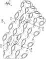
图8A至图8F是附属物800的示例性实施方案,该附属物具有组织接触表面802和仓接触表面804。附属物800包括互连的重复无撑条单元格810,其中的一个单元格在图9A至图9B中更详细地示出。虽然附属物800被示出为具有各自具有20个重复单元格810的四个纵向排(L1、L2、L3、L4),本领域的技术人员将理解,附属物的单元格的排数和数量可至少取决于附属物将被施加到其上的钉仓和/或砧座的尺寸和形状,并且因此附属物不限于图中所示的纵向排和单元格的数量。另外,虽然仅示出了一种类型的重复的无撑条单元格,但是在其他实施方案中,附属物可由第一重复的无撑条单元格和不同于该第一重复的无撑条单元格的第二重复的无撑条单元格的组合形成等。FIGS. 8A-8F are exemplary embodiments of an
鉴于附属物800由具有基本相同的结构构型(例如,在制造公差内标称相同)的重复单元格810形成,以下讨论关于一个重复单元格810。如图9A至图9B所示,重复单元格810具有顶部部分812、底部部分814和在其间延伸的中间部分816。Given that
在该例示的实施方案中,重复单元格810被构造为Schwarz-P结构,并且因此,单元格810的表面轮廓由最小表面限定。也就是说,单元格810的外部表面820和内部表面822各自由最小表面限定。因此,在该例示的实施方案中,外部表面820和内部表面822通常是凹形的,从而形成单元格810的弓形侧面821。另外,内部表面822限定单元格810的内部体积824。因此,单元格810可以被表征为是空心的。Schwarz-P最小表面可功能性地表示为:cos(x)+cos(y)+cos(z)=0。In the illustrated embodiment, the repeating
单元格810还包括连接接口826,该连接接口可用于将单元格810互连到其他单元格810,从而形成图8A至图8E中所示的附属物800。在该例示的实施方案中,单元格包括六个连接接口826,该六个连接接口形成单元格810的六个最外侧表面,例如,顶部和底部最外侧表面827a、827b、左和右最外侧表面829a、829b以及前和后最外侧表面831a、831b。顶部和底部最外侧表面827a、827b相对于彼此是大致平面的(例如,在制造公差内是平面的)并且在x方向上偏移,左右最外侧表面829a、829b相对于彼此是大致平面的(例如,在制造公差内是平面的)并且在y方向上偏移,并且前后最外侧表面831a、831b相对于彼此是大致平面的(例如,在制造公差内是平面的)并且在z方向上偏移。因此,单元格810的总外表面包括平面表面(例如,最外侧表面827a、827b、829a、829b、831a、831b)和非平面表面(例如,在连接接口826之间延伸的外部表面820)。另外,由于附属物800仅由重复单元格810形成,因此包括最顶部外表面812a的顶部部分812形成附属物800的组织接触表面802,并且单元格的底部部分814的最底部外表面814a(例如,在x方向上)形成附属物800的仓接触表面804。因此,组织接触表面802由平面表面和非平面表面形成。
另外,基于重复单元格810的总体几何形状和它们彼此对应的连接接口826处的相互连接,所得附属物800的总外表面由被非平面表面分开的大致平面的(例如,制造公差内是平面的)表面形成。如图所示,附属物800的顶部和底部最外侧表面850a、850b距在YZ平面内延伸的平分线最远,附属物800的左和右最外侧表面852a、852b距在XZ平面内延伸的平分线最远,并且附属物的前和后最外侧表面854a、854b距在XY平面内延伸的平分线最远。另外,如图所示,顶部和底部最外侧表面850a、850b相对于彼此是大致平面的(例如,在制造公差内是平面的)并且在x方向上偏移,左右最外侧表面852a、852b相对于彼此是大致平面的(例如,在制造公差内是平面的)并且在y方向上偏移,并且前后最外侧表面854a、854b相对于彼此是大致平面的(例如,在制造公差内是平面的)并且在z方向上偏移。因此,这些最外侧表面850a、850b、852a、852b、854a、854b形成附属物800的外表面的平面段。可以理解的是,在这些最外侧表面850a、850b、852a、852b、854a、854b之间延伸的附属物800的部分由相邻单元格810的外部表面820限定,从而形成附属物800的外表面的非平面表面。Additionally, based on the overall geometry of the repeating
如进一步所示,六个连接接口826限定与单元格810的内部体积824流体连通的相应圆形开口。因此,单元格810在所有六个笛卡尔侧面(在图9B中表示为箭头1、2、3、4、5、6)中具有开口。这些开口可提供多种功能,例如:促进与相邻单元的连接;产生开口,该开口可允许当附属物缝合到组织时立即组织生长;允许排出在所得附属物的生产中使用的制造材料,例如在3D制造过程期间使用的材料;允许体液易于转移整个附属物;有助于附属物的机械特性,例如,产生阻断附属物的致密化的压缩轮廓的机械特性;和/或最小化完全压缩的附属物的固体高度。As further shown, the six
此外,当单元格810在对应的连接接口(例如,至少两个连接接口)处彼此互连时,在其间形成中空管状互连件828(例如,内腔),如图8D至图8E所示,该互连件允许互连单元格810的内部体积824彼此流体连通。因此,通道或路径的连续网络存在于附属物内。因此,当附属物800被缝合到组织(T)并且处于组织部署状态时,如图8G所示,一种或多种流体(包括进入附属物800中的细胞),例如通过至少一个单元格810的顶部部分812的连接接口826a的开口,因此可在组织部署状态中通过互连单元格迁移通过附属物800,如图8G所示,并且因此可最终加速附属物800内的组织向内生长。也就是说,虽然附属物800处于组织部署状态,但是中空管状互连件828的至少一部分可至少部分地维持单元格810的至少一部分或通过所有内部体积之间的流体连通,并且从而鼓励在整个附属物800中的细胞移动性。Furthermore, when the
虽然中空管状互连件828限定了可具有各种尺寸(例如,直径)的开口,但是在一些实施方案中,该开口的直径可以是约100微米至3500微米。例如,开口的直径可以是约100微米至2500微米或约500微米至2500微米。在某些实施方案中,开口的直径可以是约945微米至1385微米。在一个实施方案中,开口的直径可大于2000微米。在某些实施方案中,所有开口的直径基本上相同(例如,在制造公差内标称相同)。如本文所用,开口的“直径”是开口的任何一对顶点之间的最大距离。While the hollow
由于重复单元格810在对应的连接接口826处彼此互连,因此附属物800呈具有预定的压缩区域830和预定的非压缩区域840的格栅结构的形式,如图8C中更清楚地示出的。虽然预定的压缩区域830和预定的非压缩区域840可具有各种构型,但在该例示的实施方案中,预定的压缩区域830由单元格810限定,并且预定的非压缩区域840呈限定在单元格810之间的空隙845的形式。在该实施方案中,每个空隙845形成在四个相邻的互连单元格810之间。例如,如图8F所示,在四个相邻单元格810a、810b、810c、810d之间限定空隙845a。因此,相邻单元格之间存在的空间限定预定的非压缩区域。换句话说,附属物的非压缩区域840不由单元格的内部体积限定。Since the repeating
如下文更详细地所述,重复单元格的结构构型可允许单元格在施加的应力下在一段时间内沿其高度H(参见图9A)在不同位置连续地变形或屈曲(例如,直到单元格的内部表面的相对侧彼此接触)。因此,在此类时间期间,单元格在施加的应力(例如,30kPa至90kPa)下时可以恒定或基本上恒定的速率变形或屈曲。换句话说,在某些实施方案中,当附属物在施加的应力下时,重复单元格的结构可导致应力平台,例如,如图11中示意性地示出的。As described in more detail below, repeating the structural configuration of a cell may allow the cell to continuously deform or buckling at different locations along its height H (see FIG. 9A ) under an applied stress over a period of time (eg, until the cell Opposite sides of the interior surfaces of the cells are in contact with each other). Thus, during such times, the cells can deform or buckle at a constant or substantially constant rate when under an applied stress (eg, 30 kPa to 90 kPa). In other words, in certain embodiments, when the appendage is under applied stress, the structure of the repeating cell can result in a stress plateau, eg, as schematically shown in FIG. 11 .
图10A至图10D示意性地示出了一个重复单元格(例如,图8A至图9B中的单元格810)在一定范围的施加的应力下时的压缩行为。具体地,在图10A中以预压缩(未变形)状态示出重复单元格1010;在图10B中以第一压缩状态示出该重复单元格,其中单元格1010的顶部部分1012和底部部分1014中的每一者开始朝向单元格1010的中间部分1016压缩,使得中间部分1016开始偏转;在图10C中以第二压缩状态示出该重复单元格,其中中间部分1016继续向外偏转;并且在图10D中以致密状态示出该重复单元格,其中中间部分1016的内部表面1018的相对侧1018a、1018b彼此接触,使得单元格810达到其固体高度。Figures 10A-10D schematically illustrate the compressive behavior of a repeating cell (eg,
在图11中示意性地示出了重复单元格1010的未变形状态U(图10A)、压缩状态C1、C2(图10B至图10C)和致密状态D(图10D)与所得附属物的应力-应变曲线之间的关系。The undeformed state U ( FIG. 10A ), compressed states C1 , C2 ( FIGS. 10B-10C ) and dense state D ( FIG. 10D ) of the repeating
附属物的应力-应变响应以由杨氏模量表征的弹性变形(弯曲)开始,例如,随着重复单元从其未压缩状态朝向其第一压缩状态开始变形。这种弹性变形继续直到达到屈服应力。一旦达到屈服应力,就可以发生应力平台,该应力平台对应于通过弹性屈曲的渐进单元格塌缩,例如,随着重复单元格继续通过其第一压缩状态和第二压缩状态变形。本领域的技术人员将理解,应力平台至少取决于制造单元格的材料的性质。应力平台继续直到致密化发生,这表示单元格在整个附属物中塌缩,例如,随着重复单元格达到其致密状态,并且因此,该附属物已达到其固体高度。The stress-strain response of the appendage begins with elastic deformation (bending) characterized by Young's modulus, eg, as the repeating unit begins to deform from its uncompressed state toward its first compressed state. This elastic deformation continues until the yield stress is reached. Once the yield stress is reached, a stress plateau can occur that corresponds to progressive cell collapse through elastic buckling, eg, as the repeating cell continues to deform through its first and second compression states. Those skilled in the art will understand that the stress plateau depends at least on the properties of the material from which the cell is fabricated. The stress plateau continues until densification occurs, which means that the cell collapses throughout the appendage, eg, as the repeating cell reaches its dense state, and thus, the appendage has reached its solid height.
本领域的技术人员将理解,附属物的应力-应变曲线取决于各种因素,例如未压缩高度、组成成分(包括材料特性)和/或结构构型。举例来说,下表1示出了示例性附属物的应力-应变响应,仅在未压缩高度(UH)上有所不同,并且该附属物在30kPa的施加应力下被压缩到具有1.75mm的第一压缩高度(CH1),在90kPa的施加应力下被压缩到具有0.75mm的第二压缩高度(CH2),并且90kPa的施加应力下被压缩到具有0.45mm的第三压缩高度(CH3)。Those skilled in the art will understand that the stress-strain curve of an appendage depends on various factors, such as uncompressed height, composition (including material properties), and/or structural configuration. As an example, Table 1 below shows the stress-strain response of an exemplary appendage that differs only in uncompressed height (UH), and the appendage was compressed to have a 1.75mm under an applied stress of 30kPa A first compressed height (CH1), compressed to a second compressed height (CH2) of 0.75 mm under an applied stress of 90 kPa, and a third compressed height (CH3) of 0.45 mm under an applied stress of 90 kPa.
表1:用于各种附属物高度的应力-应变关系Table 1: Stress-strain relationships for various appendage heights

在另一实施方案中,基于重复的无撑条单元格可以是调整的Schwarz-P结构。例如,Schwarz-P结构可在一个或多个方向上拉伸以形成经拉伸的Schwarz-P结构,例如,如图12A所示。另选地或除此之外,在某些实施方案中,可以使Schwarz-P结构的壁厚变薄。例如,如图12B所示,Schwarz-P结构被拉伸并变薄。在又一实施方案中,如图12C所示,Schwarz-P结构可被裁剪,例如,其中Schwarz-P结构的顶部部分HT(参见图9A)和/或底部部分HB(参见图9A)的高度被减小。另选地或除了前述示例性调整之外,可通过Schwarz-P结构的壁添加附加的开口,例如,如图12D所示,这可以帮助使所得附属物致密化。In another embodiment, the repeat-based unstretched cells can be adjusted Schwarz-P structures. For example, Schwarz-P structures can be stretched in one or more directions to form stretched Schwarz-P structures, eg, as shown in Figure 12A. Alternatively or in addition, in certain embodiments, the wall thickness of the Schwarz-P structure can be thinned. For example, as shown in Figure 12B, the Schwarz-P structure is stretched and thinned. In yet another embodiment, as shown in Figure 12C, the Schwarz-P structure may be tailored, eg, wherein the top portionHT (see Figure 9A) and/or the bottom portionHB (see Figure 9A) of the Schwarz-P structure height is reduced. Alternatively or in addition to the foregoing exemplary adjustments, additional openings can be added through the walls of the Schwarz-P structure, eg, as shown in Figure 12D, which can help densify the resulting appendages.
基于重复的无撑条单元格可采用其他TPMS结构的形式。例如,如图13A中所示,基于无撑条的单元格1300可由具有金刚石最小面积的片状金刚石结构形成,该金刚石最小面积具有Schwarz D表面格栅结构。这种特定的最小表面被称为“金刚石”,因为其具有两个相互交织的全等迷宫,其中每个迷宫具有金刚石键结构的管状形式的形状。Schwarz D可被功能性地表达为:Repeat-based unstretched cells can take the form of other TPMS structures. For example, as shown in FIG. 13A, a strut-free based
sin(x)sin(y)sin(z)+sin(x)cos(y)cos(z)+cos(x)sin(y)cos(z)+cos(x)cos(y)sin(z)=0。sin(x)sin(y)sin(z)+sin(x)cos(y)cos(z)+cos(x)sin(y)cos(z)+cos(x)cos(y)sin(z )=0.
图13B中示出了由重复单元格1300和因此片状金刚石结构形成的示例性附属物1310。
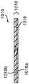
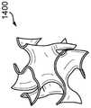
在另一实施方案中,如图14A所示,基于无撑条的单元格1400可以是螺旋结构。螺旋最小表面可被功能性地表达为:In another embodiment, as shown in Figure 14A, strut-free based
sin(x)cos(y)+sin(y)cos(z)+sin(z)cos(x)=0。sin(x)cos(y)+sin(y)cos(z)+sin(z)cos(x)=0.
图14B中示出了由重复单元格1500和因此螺旋结构形成的示例性附属物1410。在其他实施方案中,基于无撑条的单元格可呈余弦结构1500(图15A)的形式或呈焦炭罐结构1600(图16A)的形式,这两种形式中的每一者由弯曲的最小表面限定。图15B和图16B示出了由相应重复单元格1500(余弦结构)、1600(焦炭罐结构)形成的示例性附属物1510、1610。
边缘条件edge condition
在一些实施方案中,某些基于无撑条的单元格当互连以形成附属物时可形成用于组织缝合的不期望的边缘条件。例如,当组织在使用期间滑动跨过附属物时,边缘条件可以使得附属物的至少一部分过早地从钉仓中脱离的方式与组织相互作用。这些边缘条件可以是几何形状的结果(例如,具有大致平面(例如,制造公差内是平面的)和非平面外表面)和构成附属物的基于无撑条的单元格的互连性。因此,为了改进这些边缘条件,并且因此抑制附属物的过早脱离,可将具有不同几何形状的外层放置在附属物的一个或多个组织接触表面的顶部。In some embodiments, certain strut-based cells, when interconnected to form appendages, can create undesired edge conditions for tissue suturing. For example, the edge condition may interact with the tissue in such a way that at least a portion of the appendage is prematurely dislodged from the staple cartridge when the tissue slides across the appendage during use. These edge conditions may be the result of geometry (eg, having substantially planar (eg, planar within manufacturing tolerances) and non-planar outer surfaces) and interconnectivity of the strut-based cells that make up the appendages. Therefore, to improve these edge conditions, and thus inhibit premature detachment of the appendage, outer layers with different geometries may be placed on top of one or more tissue contacting surfaces of the appendage.
重新参考图9A至图9B,如上所述,Schwarz-P结构810具有形成在单元格810的连接接口826之间延伸的弓形侧面821的非平面外部表面。因此,当Schwarz-P结构810互连以形成附属物诸如图8A至图8F中的附属物800时,组织接触表面可形成具有平面和非平面表面,如图8A至图8B中的组织接触表面802。这是至少每个单元格810的顶部部分812的结构构型(例如,暴露的最顶部外表面827a和顶部部分812的弓形侧面821)以及它们之间的间隔开关系的结果。因此,附属物的边缘条件可通过施加具有大致平面(例如,在制造公差内平面)的几何形状的外层来最小化,该几何形状定位在附属物的至少一个另外的组织接触表面上,如图8A至图8F中的附属物800的组织接触表面802。因此,这可在放置缝合装置期间降低附属物上的组织负载(施加的应力)。另外,这可简化附属物与仓之间的附接要求。Referring back to FIGS. 9A-9B , as described above, the Schwarz-
虽然外层可具有各种构型,但在一些实施方案中,外层可由撑条的一个或多个平面阵列(图17A至图17C)形成,而在其他实施方案中,该外层可呈膜的形式(图18)。While the outer layer may have various configurations, in some embodiments the outer layer may be formed from one or more planar arrays of struts (FIGS. 17A-17C), while in other embodiments the outer layer may be in the form of membranes (Figure 18).
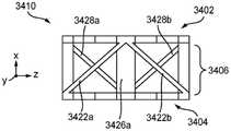
图17A至图17C示出了具有由互连重复的单元格1704和至少一个平面阵列1706、1708形成的第一格栅结构1702的示例性附属物1700。每个单元格1704类似于图9A至图9B中的单元格810,并且因此本文未详细描述公共特征。在该例示的实施方案中,存在两个平面阵列1706、1708,其中第一平面阵列1706(例如,在YZ平面中)延伸跨过第一格栅结构1702的顶部面向组织的表面1712,并且第二平面阵列1706(例如,在XZ平面中)延伸跨过第一格栅结构1702的至少一个侧面面向组织的表面1714。在其他实施方案中,可省略第一平面阵列1706或第二平面阵列1708。在另外的实施方案中,附属物1700可包括附加的平面阵列。FIGS. 17A-17C illustrate an
虽然平面阵列1706、1708可具有各种构型,但在该例示的实施方案中,第一平面阵列1706和第二平面阵列1708各自包括平行于附属物1700的纵向轴线(LA)并沿着该纵向轴线延伸的纵向撑条1716。虽然未示出,但也能设想可将附加的撑条添加到第一平面阵列1706和第二平面阵列1708。例如,在一个实施方案中,第一平面阵列1706和/或第二平面阵列1708可包括相对于纵向轴线以一角度延伸并且与第一纵向撑条和/或第二纵向撑条相交(例如,由此产生重复的X图案)的交叉撑条。While the
在使用中,当附属物1700被可释放地保持在仓上,诸如图1至图2C中的仓200时,附属物1700与设置在仓内的钉排重叠。因此,第一平面阵列1706可添加到附属物1700的最终固体高度,并且因此加速其致密化。然而,为了最小化第一平面阵列1706对致密化的影响,第一平面阵列1706可以其不与钉排重叠的方式来设计。例如,如图17A至图17C所示,第一平面阵列1706被分成四个间隔开的部分1706a、1706b、1706c、1706d,使得三个间隙1718、1720、1722在其间形成并沿着附属物1700的纵向轴线(LA)。如图17C所示,这三个间隙1718、1720、1722可与仓(未示出)的三个钉排1724、1726、1728重合,并且因此第一平面阵列1706将不会被捕获,或在部署期间由钉最小化。In use, when the
如上所述,在一些实施方案中,可吸收膜可被定位在格栅结构的非平面面向组织的表面中的至少一者的至少一部分上,以由此基本上防止组织在该组织滑动跨过附属物时引起该附属物从仓过早地脱离。也就是说,可吸收膜可以使边缘条件最小化,从而减少否则将存在于附属物的组织接触表面上的摩擦。As described above, in some embodiments, an absorbable film can be positioned on at least a portion of at least one of at least one of the non-planar tissue-facing surfaces of the grid structure to thereby substantially prevent tissue from sliding across the tissue causes the appendage to disengage prematurely from the bin. That is, the absorbable film can minimize edge conditions, thereby reducing friction that would otherwise exist on the appendage's tissue-contacting surface.
图18示出了设置在仓1801上的附属物1800的示例性实施方案。附属物1800包括具有设置在其至少一部分上的可吸收膜1804的格栅结构1802。类似于图8A中的附属物800的格栅结构的格栅结构1802由互连重复单元格1806形成,该重复单元格中的每一个重复单元格类似于图9A至图9B中的单元格810,并且因此本文未详细描述公共特征。如图所示,可吸收膜1804可被设置在格栅结构1802的所有面向组织的表面上,在该例示的实施方案中,该可吸收膜包括顶部面向组织的表面1808(例如,在x方向上延伸)、第一纵向侧表面1810a(例如,在z方向上延伸)、第二相对纵向侧表面1810b、第一横向侧表面1812a(例如,在y方向上延伸)和第二相对横向侧表面(被遮挡)。在其他实施方案中,可吸收膜不被设置在格栅结构的所有面向组织的表面上,例如,第一横向侧表面和/或第二横向侧表面。FIG. 18 shows an exemplary embodiment of an
该可吸收膜可具有多种构型。例如,在一些实施方案中,可吸收膜被设计成具有在附属物在施加的应力下和/或由一种或多种材料形成时标称影响附属物的致密化的厚度,该一种或多种材料有助于减少组织接触层的摩擦以进行组织操作。在一些实施方案中,可吸收膜的厚度可小于或等于约15微米,例如约5微米至15微米,或约8微米至11微米。在一个实施方案中,可吸收膜可由聚二氧六环酮形成。The absorbable film can have a variety of configurations. For example, in some embodiments, the absorbable film is designed to have a thickness that nominally affects the densification of the appendage under applied stress and/or when formed from one or more materials, the one or Various materials help reduce friction of the tissue-contacting layer for tissue manipulation. In some embodiments, the absorbable film may have a thickness of less than or equal to about 15 microns, eg, about 5 to 15 microns, or about 8 to 11 microns. In one embodiment, the absorbable film may be formed from polydioxanone.
附接特征部Attachment Features
在一些实施方案中,基于非撑条的附属物包括一个或多个附接特征部,该一个或多个附接特征部至少部分地沿着附属物的长度延伸并且被构造成能够接合钉仓,从而在钉部署之前将附属物保持在仓上。该一个或多个附接特征部可具有多种构型。例如,一个或多个附接特征部可以是通道附接件(图19A至图21),(图22A至图22B)和/或端部附接件(图24至图25),该通道附接件被构造成能够接合(例如,压接或扣入到)在钉仓中的相对纵向边缘之间形成的细长切割狭槽,该端部附接件被构造成能够与限定在钉仓内的凹陷端部通道接合。除了下文详细讨论的差异之外,附属物1900、2000、2100、2200基本上类似于图8A至图8F中的附属物800,并且因此本文未详细讨论公共特征。In some embodiments, the non-strut-based appendage includes one or more attachment features extending at least partially along the length of the appendage and configured to engage a staple cartridge , thereby maintaining the appendage on the cartridge prior to staple deployment. The one or more attachment features may have various configurations. For example, the one or more attachment features may be channel attachments (FIGS. 19A-21), (FIGS. 22A-22B) and/or end attachments (FIGS. 24-25), which The adapter is configured to engage (eg, crimp or snap into) an elongated cutting slot formed between opposing longitudinal edges in the staple cartridge, the end attachment being configured to engage (eg, crimp or snap into) an elongated cutting slot defined in the staple cartridge The inner recessed end channel engages. Apart from the differences discussed in detail below,
在一些实施方案中,通道附接件可包括一个或多个可压缩构件,该一个或多个可压缩构件在结构上被构造成能够被插入到钉仓的纵向狭槽中以接合纵向狭槽的相对壁。在某些实施方案中,一个或多个可压缩构件可包括可压缩开口,该可压缩开口例如沿着附属物的仓接触表面的长度在纵向方向上延伸穿过其中。In some embodiments, the channel attachment can include one or more compressible members structurally configured to be insertable into longitudinal slots of the staple cartridge to engage the longitudinal slots the opposite wall. In certain embodiments, the one or more compressible members may include a compressible opening extending therethrough in a longitudinal direction, eg, along the length of the appendage's cartridge-contacting surface.
图19A至图19B示出了附属物1900的示例性实施方案,该附属物包括具有通过至少一个公共细长接头1916互连的两个可压缩构件1912、1914的通道附接件1910。虽然两个可压缩构件1912、1914可具有各种构型,但在该例示的实施方案中,每个可压缩构件1912、1914呈细长杆的形式,该细长杆具有跨其宽度截取的三角形横截面形状(例如,在y方向上),其中中空三角形通道1912a、1914a沿其长度延伸穿过其中(例如,在z方向上)。如图所示,两个细长杆1912、1914在对应顶点处互连,从而形成细长接头1916,该细长接头限定具有窄的厚度的中心连接区域(例如,在x方向上)。如图19B所示,当附属物1900被设置在类似于图1至图2C中的仓200的仓1901上时,至少一个细长接头1916(并且因此中央连接区域)被定位成与纵向狭槽1903的相对壁1903a、1903b等距,如图19所示。因此,中心连接区域与切割构件的推进线对准,并且因此由于中央连接区域的窄的宽度,因此可以最小化或防止在切割构件推进通过附属物1900时堵塞该切割构件的风险。也就是说,中心连接区域使切割构件在其推进穿过纵向狭槽1903时将需要以其他方式切割的附加的附属物最小化。另外,中空三角形通道1912a、1914a减小推进线的每一侧上的材料的量,这也可在附属物进一步推进通过纵向狭槽1903时使该附属物的切割边缘与切割构件的结合最小化。FIGS. 19A-19B illustrate an exemplary embodiment of an
虽然通道附接件1910的总宽度WC可发生变化,但在该例示的实施方案中,总宽度WC大于纵向狭槽1903的宽度WL(例如,两个相对的槽壁1903a、1903b之间的距离)。因此,当通道附接件1910插入到纵向狭槽1903中时,由于由中空三角形通道1912a、1914a产生的向外横向力,可压缩构件变形并接合(例如,压缩抵靠)相应狭槽壁1903a、1903b。因此,在可压缩构件1912、1914与仓1901的相应狭槽壁1903a、1903b之间产生压力配合或摩擦配合。Although the overall widthWC of the
通道附接件可具有其他构型(例如,形状和/或尺寸)。例如,如图20所示,附属物2000类似于图8A至图8X中所示的附属物800,除了附属物2000还包括呈细长突出部形式的通道附接件2010,该通道附接件从附属物2000的仓接触表面2004向外延伸并且被定位在两个内排重复单元格2010a、2012a之间。细长突出部2010被构造成能够被插入到仓的纵向狭槽中,如图2A和图2C中仓200的纵向狭槽210。Channel attachments may have other configurations (eg, shapes and/or dimensions). For example, as shown in FIG. 20,
虽然细长突出部2010可具有各种构型,但在该例示的实施方案中,细长突出部2010由两个可压缩的纵向杆2010a、2010b形成,其中横杆2010c在其间延伸。在一些实施方案中,细长突出部2010的宽度(例如,在y方向上)大于钉仓的纵向狭槽的宽度(例如,两个相对狭槽壁之间的距离)。因此,当细长突出部2010插入到纵向狭槽中时,如图2A至2C中仓200的纵向狭槽210,这两个纵向杆被构造成能够由于由横杆2010c产生的向外横向力而接合(例如,压缩抵靠)相对槽壁。因此,在细长突出部2010与仓的狭槽壁之间形成压力配合或摩擦配合。While the
图21示出了具有通道附接件的附属物2100的另一实施方案。附属物2100类似于图20所示的附属物2000,不同的是通道附接件呈离散突出部2110(图21中仅示出两个)的形式,该离散突出部沿着附属物2100的纵向轴线LA相对于彼此间隔开。虽然突出部2110可具有各种构型,但在该例示的实施方案中,每个突出部2110呈具有椭圆形形状的环形凸台的形式。在其他实施方案中,突出部2110可以是任何其他合适的形状和/或相对于彼此在尺寸/形状上变化。每个环形凸台2110可被构造成可压缩的,并且在一些实施方案中,其尺寸被设定成使得每个凸台的宽度(例如,在y方向上)可大于钉仓的纵向狭槽(例如,两个相对狭槽壁之间的距离)的宽度,如图2A至图2C中的钉仓200中的纵向狭槽210。因此,当将离散的环形凸台2110插入到仓的纵向狭槽中时,它们的外表面2110a被构造成能够由于环形凸台的向外径向力接合(例如,压缩抵靠)相对的狭槽壁。因此,在环形凸台2110a与纵向狭槽的狭槽壁之间形成压力配合或摩擦配合。Figure 21 shows another embodiment of an
另选地或除此之外,在一些实施方案中,附属物可包括被构造成能够接合附属物的对应边缘附接特征部的边缘附接特征部。例如,如图22A至图22C所示,附属物2200可包括三组相对夹具2202a、2202b、2204a、2204b、2206a、2206b,其各自横向向外并且远离附属物2200的相对的外侧表面2200a、2200b延伸。虽然三组夹具2202a、2202b、2204a、2204b、2206a、2206b可具有各种构型,但在该例示的实施方案中,三组夹具2202a、2202b、2204a、2204b、2206a、2206b各自具有与仓2201的相应边缘附接特征部2208a、2208b、2210a、2210b、2212a、2212b接合的钩形构型。在该例示的实施方案中,每个边缘附接特征部2208a、2208b、2210a、2210b、2212a、2212b具有倒置的L形构型,从而产生从钉仓2201横向向外延伸的凸缘(图22B至图22C中仅详细示出一个凸缘)。Alternatively or additionally, in some embodiments, the appendages may include edge attachment features configured to engage corresponding edge attachment features of the appendages. For example, as shown in FIGS. 22A-22C ,
图22C中示出了附属物2200的一个夹具2204a和仓2201的一个凸缘2210a的接合。为简单起见,省略了附属物2200的重复单元格。如图所示,夹具2204的端部部分2214的内表面2214a接合凸缘2210a的外底表面2216,从而使凸缘2210a的外表面2218的一部分抵靠夹具2204a的内表面2220的对应部分嵌套(例如,凸出接合/凹入接合)。另外,如图22C所示,凸缘2210a向外偏置,并且因此,当凸缘2210a的外表面2218的一部分被接合时,它们被压靠在夹具2204a的内表面2220a的对应部分上。The engagement of a
图23A至图23B示出了具有三组相对夹具2302a、2302b(部分地被遮挡)、2304a、2304b(部分地被遮挡)、2306a、2306b(部分地被遮挡)的附属物的另一实施方案,该相对夹具被构造成能够接合钉仓2301的对应的一组相对的接纳构件2308、2310(部分地被遮挡)、2312、2314(部分地被遮挡)、2316、2318(部分地被遮挡)。Figures 23A-23B show another embodiment of an appendage with three sets of opposing clamps 2302a, 2302b (partially occluded), 2304a, 2304b (partially occluded), 2306a, 2306b (partially occluded) , the opposing clamps are configured to engage a corresponding set of opposing receiving
在该例示的实施方案中,每个夹具在结构上相同并且具有倒置的T形构型。另外,如图所示,每组接纳构件在结构上相同,并且包括间隔开并且彼此面对以在其间形成t形空隙的两个倒置的L形构件。举例来说,图23B中更详细地示出了一个夹具2302a与其对应的一组接纳构件2308a、2308b的接合。如图所示,夹具2302a的横向段2316a、2316b(例如,在z方向上延伸)被构造成能够与每个L形构件2308a、2308b的相应内表面(仅示出一个内表面3118)接合,并且夹具2302a的竖直段2320(例如,在x方向上延伸)被构造成能够定位在L形构件2308a、2308b的两个面向表面(仅示出一个面向表面2322)之间。因此,竖直段2320可帮助维持附属物2300相对于钉仓2301(并且因此相对于设置在其中的钉(未示出))的纵向对准。在使用期间,竖直段2320还可帮助防止夹具2302a与对应的一组接纳构件2308a、2308b以及因此来自仓2301的附属物2300的过早脱离。In the illustrated embodiment, each clamp is structurally identical and has an inverted T-shaped configuration. Additionally, as shown, each set of receiving members is identical in structure and includes two inverted L-shaped members spaced apart and facing each other to form a t-shaped gap therebetween. For example, the engagement of one
另选地或除此之外,在一些实施方案中,附属物可包括端部附接特征部,例如相对的近侧组和远侧组的凸台,该凸台被构造成能够接合(例如,压力配合)到限定在钉仓中的对应的近侧组和远侧组的凹陷部中。例如,在一个实施方案中,附属物可具有矩形凸台,该矩形凸台被构造成能够接合图24中的钉仓2400的近侧组和远侧组的矩形凹陷部2402a、2402b、2404a、2404b。在另一实施方案中,附属物可以具有圆形凸台,该圆形凸台被构造成能够接合图25中的钉仓2500的近侧组和远侧组的圆形凹陷部2502a、2502b、2504a、2504b。Alternatively or additionally, in some embodiments, the appendage may include end attachment features, such as opposing proximal and distal sets of bosses configured to engage (eg, , press fit) into the recesses defined in the corresponding proximal and distal sets in the staple cartridge. For example, in one embodiment, the appendage may have a rectangular boss configured to engage the
如上所述,在某些实施方案中,钉仓可包括呈凹陷通道形式的表面特征部,例如,如图2A和图2C所示的凹陷通道216、218、220。在此类实施方案中,附属物可被设计成与凹陷通道接合以在附属物与钉仓之间实现可释放的附接机构,即使当纵向钉排内的钉的频率(例如,每长度钉排内的钉的数量)不同于(例如,大于)对应的纵向单元格排内的重复单元格的频率(例如,每长度单元格排的单元格的数量)时。As noted above, in certain embodiments, the staple cartridge may include surface features in the form of recessed channels, eg, recessed
图26A至图26C示出了设置在钉仓2602上的附属物2600,该钉仓类似于图2A至图2C中的钉仓200,并且因此本文未详细描述公共特征。钉仓2602包括以纵向排2604a、2604b、2604c、2606a、2606b、2606c布置的钉腔和围绕每个钉腔2604a、2604b、2604c、2606a、2606b、2606c的凹陷通道。如图所示,第一凹陷通道2608围绕每个第一钉腔2604a、2606a,第二凹陷通道2610围绕每个第二钉腔2604b、2606b,并且第三凹陷通道2612围绕每个第三钉腔2604c、2606c。第一凹陷通道、第二凹陷通道和第三凹陷通道各自包括相应的底板2614、2616、2618,该底板位于距钉仓2602的顶表面2602a的相应高度(例如,在x方向上延伸)处。在该例示的实施方案中,相应的高度相同,而在其他实施方案中,相应的高度可不同。Figures 26A-
虽然附属物2600可具有各种构型,但在该例示的实施方案中,附属物2600由重复单元格2620和从多个单元格2620的至少一部分延伸的附接特征部2622形成。附接特征部2622各自被构造成能够被插入到钉仓2602的凹陷通道2608、2610、2612的至少一部分中并与该至少一部分接合,从而在钉部署之前将附属物2600保持到钉仓2602。While the
虽然附接特征部2622可具有各种构型,但是每个附接特征部具有不同的几何形状,使得每个附接特征部可接合相应的凹陷通道。与钉仓2602的钉腔2604a、2604b、2604c、2606a、2606b、2606c的钉2605的频率相比,这种几何形状的差异是由于单元格的频率的差异。因此,附接特征部2622被定位在对应于凹陷通道2608、2610、2612的预定位置处的相应单元格2620上。如图26A所示,并且在图26B至图26C中更详细地示出了附属物2600的一半(例如,左半部),附接特征部2622的相应几何形状被构造成能够接合凹陷通道2608、2610、2612的相对于钉仓2602的纵向轴线LA横向向外指向的相应顶点2608a、2610a、2610b、2612a。在其他实施方案中,附接特征部的几何形状可被构造成能够接合凹陷通道的其他部分。While the attachment features 2622 can have various configurations, each attachment feature has a different geometry such that each attachment feature can engage a corresponding recessed channel. This difference in geometry is due to the difference in the frequency of the cells compared to the frequency of the
附接特征部2622的几何形状可相对于仓的纵向轴线横向和/或纵向变化。几何变化至少取决于单元格2620相对于钉2605的频率的频率和钉腔2604a、2604b、2604c、2606a、2606b、2606c的形状。例如,附接特征部2622可相对于彼此在高度(例如,在x方向上)、宽度(例如,在y方向上)、长度(例如,在z方向上)和形状中的至少一者上变化。例如,如图26B所示,从第一重复单元格2620a延伸的第一附接特征部2622a的高度H1大于从第二重复单元格2620b延伸的第二附接特征部2622b的高度H2,并且因此第一附接特征部2622a和第二附接特征部2622b的高度相对于仓2602的纵向轴线LA横向地不同。在该例示的实施方案中,如图26A和图26B进一步所示,第一附接特征部2622a和第二附接特征部2622b中的每一者的形状也相对于仓2602的纵向轴线LA横向地变化。第一附接特征部2622a具有圆柱形构型,并且第二附接特征部2622b具有弓形构型。另选地或除此之外,两个或更多个附接特征部的长度可沿着仓2602的纵向轴线AL变化。例如,如图26A所示,第三重复单元格2620c和第四重复单元格2620d分别包括第三附接特征部2622c和第四附接特征部2622d,该附接特征部沿着仓2602的纵向轴线LA在长度(例如,在z方向上延伸)和形状上变化。在该例示的实施方案中,第三附接特征部2622c具有圆柱形构型,而第四附接特征2622d具有三角形构型。The geometry of the attachment features 2622 may vary laterally and/or longitudinally relative to the longitudinal axis of the cartridge. The geometric variation depends at least on the frequency of the
在某些实施方案中,附接特征部的形状和/或高度的横向变化可对应于凹陷通道的横向变化。例如,虽然未示出,但在一些实施方案中,凹陷通道的至少一部分的壁可相对于仓的纵向轴线以一角度延伸,并且因此一个或多个附接特征部可在形状和/或高度上变化以对应于该凹陷通道。在其他实施方案中,凹陷通道的长度可横向地变化,并且一个或多个附接特征部可在形状和/或高度上变化以对应于该凹陷通道。In certain embodiments, lateral changes in the shape and/or height of the attachment features may correspond to lateral changes in the recessed channels. For example, although not shown, in some embodiments the walls of at least a portion of the recessed channel may extend at an angle relative to the longitudinal axis of the cartridge, and thus the one or more attachment features may vary in shape and/or height change up to correspond to the recessed channel. In other embodiments, the length of the recessed channel may vary laterally, and the one or more attachment features may vary in shape and/or height to correspond to the recessed channel.
单元格频率cell frequency
基于非撑条的附属物可在厚度上纵向地(例如沿着其长度,例如在z方向上)和/或横向地(例如沿着其宽度,例如在y方向上)变化。因此,在纵向钉排内的钉的频率(例如,每长度钉排内的钉的数量)不同于(例如,大于)对应的纵向单元格排内的重复单元格的频率(例如,每长度单元格排的单元格的数量)的情况下,每个钉的钉腿可推进通过附属物的不同部分,其中每个部分具有相对厚度差,如图27所示。A non-strut-based appendage may vary in thickness longitudinally (eg, along its length, eg, in the z-direction) and/or laterally (eg, along its width, eg, in the y-direction). Thus, the frequency of staples within a longitudinal row of staples (eg, the number of staples within a row of staples per length) is different (eg, greater than) from the frequency of repeating cells within a corresponding row of longitudinal cells (eg, cells per length). number of cells in the row), the spike legs of each spike may be advanced through different sections of the appendage, where each section has a relative difference in thickness, as shown in FIG. 27 .
图27示出了缝合组件2700的示例性实施方案,该缝合组件具有钉仓2702,如图1至图2C中的钉仓200,并且具有以纵向排布置的钉(仅示出了第一纵向钉排2712的一部分的四个钉2704、2706、2708、2710)。附属物2714被设置在钉仓2702的顶表面2702a上。附属物2714包括以纵向轴线(仅示出了第一纵向单元格排2717的一部分)布置的互连的重复无撑条单元格,如图8A至图9C中的重复单元格810(仅示出了五个重复单元格2716a、2716b、2716c、2716d、2716e)。如图所示,第一纵向单元格排2717与第一纵向钉排2712重叠,并且钉2704、2706、2708、2710的频率不同于单元格2716a、2716b、2716c、2716d、2716e(例如,非多个)的频率。因此,例如,当附属物2714缝合到组织时,相应钉2704、2706、2708、2710的每个钉腿2704b、2706a、2706b、2708a、2708b、2710a与第一纵向单元格排2712的不同相应部分2718、2720、2722、2724、2726(并且因此附属物2714)对准,并且因此将穿透该不同相应部分。另外,如图27所示,由于重复单元格2716a、2716b、2716c、2716d、2716e的结构构型(例如,通常不是正方形),这些不同部分2718、2720、2722、2724、2726、2728中的至少两者或更多者可具有不同的相对厚度T1、T2、T3、T4、T5(例如,厚的厚度和薄的厚度),并且因此被捕获在击发钉内的附属物2714的厚度将在缝合到一致组织的相邻钉之间变化。Figure 27 shows an exemplary embodiment of a
在一些实施方案中,附属物的相对厚度的差异可与钉腿长度的对应差异配对。例如,当钉和单元格频率相同时,被构造成能够推进通过附属物的较厚部分的任何钉的腿的长度可比被构造成能够推进通过附属物的较薄部分的任何钉的腿长。另选地或除此之外,相对厚度的差异可与砧座凹坑深度的对应差异配对,或者,如果钉驱动器处于相同高度,则可与第一钉腿到第二钉腿之间的组织间隙差异配对(如果钉驱动器处于相同高度)。In some embodiments, differences in the relative thicknesses of the appendages can be paired with corresponding differences in staple leg lengths. For example, any staple configured to advance through a thicker portion of the appendage may have a longer leg than any staple configured to advance through a thinner portion of the appendage when the staple and cell frequencies are the same. Alternatively or in addition, the difference in relative thickness can be paired with a corresponding difference in the depth of the anvil pockets, or, if the staple drivers are at the same height, with the tissue between the first to second staple legs Clearance differential pairing (if the peg drivers are at the same height).
图28A示出了与图27中的缝合组件2700类似的缝合组件2800的示例性实施方案,除了附属物2801的结构构型已被修改成使得钉频率和单元格频率相同。因此,每个钉2804、2806、2808的第一钉腿2804a、2806a、2808a被构造成能够穿过具有相同第一厚度T1的附属物的相应部分,并且每个钉2804、2806、2808的第二钉腿2804b、2806b、2808b被构造成能够穿过具有相同第二厚度T2的附属物2801的相应部分。如图所示,第一厚度T1大于第二厚度T2,并且因此以抵消厚度的差异,每个钉2804、2806、2808的第一腿长度L1可大于第二腿长度L2。在该例示的实施方案中,每个钉2804、2806、2808的冠部2804c、2806c、2808c具有非平面构型(例如,台阶式构型)以实现钉腿长度的差异。另外,当部署钉2804、2806、2808并且附属物2801被缝合到组织T时,每个钉将具有两个不同的形成的钉高度H1、H2,如图28B所示。图29示出了与缝合组件2800类似的缝合组件2900的另一示例性实施方案,除了每个钉2904、2906、2908的冠部2904c、2906c、2908c是大致平面的(例如,在制造公差内通常是直线或线性的),并且因此,第一钉的形成的钉高度将是大致均匀的(例如,在制造公差内标称相同)。28A shows an exemplary embodiment of a
基于撑条的附属物strut-based appendages
如上所述,附属物可包括由基于撑条的单元格(例如,由平面互连撑条限定)形成的格栅结构。通常,此类附属物可包括组织接触层、仓接触层和内部结构(例如,屈曲结构)。内部结构通常包括将组织接触层和仓接触层以间隔开的关系连接在一起的撑条(例如,间隔撑条)。这些撑条可被构造成能够在附属物在应力下压缩时塌缩而不会彼此接触。因此,可延迟附属物的致密化,并且因此可在较高的应变下发生。As described above, the appendages may comprise grid structures formed from strut-based cells (eg, defined by planar interconnecting struts). Typically, such appendages may include tissue-contacting layers, cartridge-contacting layers, and internal structures (eg, flexural structures). The internal structure typically includes struts (eg, spacer struts) that connect the tissue-contacting layer and the cartridge-contacting layer together in a spaced relationship. The struts may be configured to collapse without contacting each other when the appendages compress under stress. Thus, the densification of the appendages can be delayed and thus can occur at higher strains.
组织接触层和仓接触层可具有各种构型。在一些实施方案中,组织接触层和仓接触层中的至少一者可包括限定开口的多个撑条。在一些实施方案中,组织接触层和仓接触层均为大致平面的(例如,在制造公差内是平面的)。组织接触层和仓接触层可沿着从附属物的第一端部延伸到第二端部的纵向轴线彼此平行定向,并且可进一步限定在其间延伸的竖直轴线。The tissue-contacting layers and cartridge-contacting layers can have various configurations. In some embodiments, at least one of the tissue-contacting layer and the cartridge-contacting layer can include a plurality of struts that define openings. In some embodiments, both the tissue-contacting layer and the cartridge-contacting layer are substantially planar (eg, planar within manufacturing tolerances). The tissue-contacting layer and the cartridge-contacting layer can be oriented parallel to each other along a longitudinal axis extending from the first end to the second end of the appendage, and can further define a vertical axis extending therebetween.
该撑条可具有各种构型。例如,在一些实施方案中,撑条可具有大致均匀(在制造公差内是均匀)的横截面,而在其他实施方案中,撑条可具有不同的横截面。在一些实施方案中,该附属物可具有在约0.1mm至0.5mm、约0.1mm至0.4mm,或约0.1mm至0.3mm范围内的平均撑条厚度。The struts can have various configurations. For example, in some embodiments, the struts can have a substantially uniform (within manufacturing tolerances) cross-section, while in other embodiments, the struts can have different cross-sections. In some embodiments, the appendages may have an average strut thickness in the range of about 0.1 mm to 0.5 mm, about 0.1 mm to 0.4 mm, or about 0.1 mm to 0.3 mm.
图30A至图30B示出了示例性基于撑条的附属物3000。附属物3000包括组织接触层3002、仓接触层3004和在其间延伸的内部结构3006。内部结构3006被构造成能够在附属物3000在施加的应力下时塌缩(压缩),并且因此导致附属物3000在缝合到组织时压缩。30A-30B illustrate an exemplary strut-based
虽然组织接触层3002和仓接触层3004可具有各种构型,但在该例示的实施方案中,它们均为大致平面的(例如,在制造公差内是平面的)。另外,组织接触层3002和仓接触层3004沿着从附属物3000的第一端部3000a延伸到第二端部3000b的纵向轴线(LA)彼此平行。如图所示,组织接触层3002和仓接触层3004是彼此的倒置图像,其中仓接触层3004的厚度(TC)大于组织接触表面3002的厚度(TT)。因此,为简单起见,以下描述是关于组织接触层3002的。然而,本领域的技术人员将理解,以下讨论也适用于仓接触层3004。While the tissue-contacting
组织接触层3002具有沿着附属物3000的纵向轴线(L)延伸的第一纵向撑条3008a、第二纵向撑条3010a和第三纵向撑条3012a,其中第二纵向撑条3010a定位在被第一纵向撑条3008a与第三纵向撑条3012a之间但与该第一纵向撑条和该第三纵向撑条间隔开。组织接触层3002还包括第一交叉撑条3014a和第二交叉撑条3016a。第一交叉撑条3014a中的每一个连接到第一纵向撑条3008a和第二纵向撑条3010a。虽然第一交叉撑条3014a可在各种不同的位置处定向,但在该例示的实施方案中,第一交叉撑条3014a相对于第一纵向撑条3008a和第二纵向撑条3010a正交地定向。类似地,第二交叉撑条3016a中的每一个连接到第二纵向撑条3010a和第三纵向撑条3012a。虽然第二交叉撑条3016a可在各种不同的位置处定向,但在该例示的实施方案中,第二交叉撑条3016a相对于第二纵向撑条3010a和第三纵向撑条3012a正交地定向。另外,如图所示,第一交叉撑条3014a在y方向上与第二交叉撑条3016a对准。
另外,第一交叉撑条3014a在第一距离D1处彼此纵向间隔开,并且第二交叉撑条在第二距离D2处彼此纵向间隔开。因此,在组织接触层3002内产生开口3018a。虽然开口3018a可具有各种尺寸和形状,但在该例示的实施方案中,D1和D2相同或基本上相同,并且因此与第一交叉撑条3014a和第二交叉撑条3016a的定向组合,所得开口3018a呈具有大致均匀尺寸(例如,在制造公差内标称相同)的矩形形式。Additionally, the first cross-braces 3014a are longitudinally spaced from each other at afirst distance D1, and the second cross-braces are longitudinally spaced from each other at asecond distance D2. Thus,
虽然内部结构3006可具有各种构型,但在该例示的实施方案中,内部结构3006包括在组织接触层3002与仓接触层3004之间延伸的间隔撑条3020。间隔撑条3020包括第一组成角度的撑条3022a、3022b和第二组成角度的撑条3024a、3024b,该两组成角度的撑条中的每一者相对于组织接触层3002和仓接触层3004以一角度(例如,45度)延伸。第一组成角度的撑条包括从组织接触表面3002的第一纵向撑条3008a延伸到仓接触层3004的第二纵向撑条3010b的第一成角度的撑条3022a,以及从仓接触层3004的第一纵向撑条3008b延伸到组织接触层3002的第二纵向撑条3010a的第二成角度的撑条3022b。因此,第一成角度的撑条3022a和第二成角度的撑条3022b沿着附属物的长度(L)交替。第二组交替成角度的撑条包括第三成角度的撑条3024a和第四成角度的撑条3024b。第三成角度的撑条3024a类似于第一成角度的撑条3022a,除了第三成角度的撑条3024a从组织接触层3002的第二纵向撑条3010a延伸到仓接触层3004的第三纵向撑条3012b。第四成角度的撑条3024b类似于第二成角度的撑条3022b,除了第四成角度的撑条3024b从仓接触层3004的第二纵向撑条3010b延伸到组织接触层3002的第三纵向撑条3012a。因此,在该例示的实施方案中,第一成角度的撑条3022a和第三成角度的撑条3024a相对于彼此在相同方向上延伸,并且第二成角度的撑条3022b和第四成角度的撑条3024b相对于彼此在相同方向上延伸。While the
如图30A进一步所示,开口3018b在仓接触层3004内在第一交叉撑条3014b之间和第二交叉撑条3016b之间产生。另外,成角度的撑条3022a、3022b、3024a、3024b与至少仓接触层3004中的对应开口3018b基本上重叠,并且如上所述,仓接触层3004具有大于组织接触层3002的厚度TT的厚度TC。因此,限定在仓接触层3004中的开口3018b可被构造成能够在附属物3000在施加的应力下压缩时随着该附属物弯曲接纳对应的成角度的撑条的至少一部分。这在内部结构3006内产生附加的空间以用于屈曲,并且因此减小附属物3000的固体高度。因此,在使用中,可延迟附属物3000的致密化,使得附属物3000可经历更宽范围的变形而不会到达其固体高度。As further shown in FIG. 30A ,
另外,通过交替成角度的撑条3022a、3022b、3024a、3024b,产生内部结构3006内的集中区3030。如图所示,此集中区3030沿着附属物在纵向方向上在第一组和第二组成角度的撑条3022a、3022b、3024a、3024b之间延伸。因此,内部结构3006内没有撑条3020与此集中区3030重叠,如图30B中更详细地示出的。换句话说,此集中区3030被设计成不含撑条的空间,其中在附属物压缩之前或期间没有撑条交叉进入该空间。因此,此集中区3030的存在可增加附属物3000的致密化点,同时将附属物缝合到组织(例如,减小附属物的固体高度)。另外,集中区可与附属物的切割线重叠,因此可减小沿着该切割线的材料的量。这可有助于促进缝合装置的切割元件的推进,并且因此使附属物的切割更容易。Additionally, by alternating the
图31A、图32A、图33A和图34A示出了各种其他示例性基于撑条的附属物3100、3200、3300和3400。每个示例性附属物具有由重复互连的基于撑条的单元格形成的格栅结构,该单元格在图31B至图31D、图32B至图32D、图33B至图33E和图34B至34E中更详细地示出。这些附属物被结构化,以便于当暴露于压缩力(例如,当缝合到组织时施加的应力)时压缩。31A, 32A, 33A, and 34A illustrate various other exemplary strut-based
图31A示出了呈格栅结构形式的另一示例性附属物3100,该格栅结构包括顶部部分3102、底部部分3104和在其间延伸的内部结构3106。顶部部分3102被构造成能够接触组织,并且因此形成附属物3100的组织接触层,而底部部分3104被构造成能够附接到仓,并且因此形成附属物3100的仓接触层。内部结构3106例如当缝合到组织时可被构造成能够在负载下压缩成变形状态。格栅由重复单元格3110的阵列形成,该重复单元格中的一个重复单元格在图31B至图31D中更详细地示出。因此,为简单起见,以下描述是关于一个单元格的顶部部分3102、底部部分3104和内部结构3106的。31A shows another
虽然顶部部分3102和底部部分3104可具有各种构型,但在该例示的实施方案中,顶部部分3102和底部部分3104是彼此的倒置图像,并且因此,为简单起见,以下描述是关于一个单元格3110的顶部部分3102的。然而,本领域的技术人员将理解,以下讨论也适用于底部部分3104。While
如图31A至图31D所示,顶部部分3102包括第一交叉撑条3112和第二交叉撑条3114以及在其间延伸的第一成角度的撑条3116和第二成角度的撑条3118。在该例示的实施方案中,第一成角度的撑条3116以第一角度从第一交叉撑条3112的第一端部延伸并且在第二交叉撑条3114的中间部分处终止,并且第二成角度的撑条3118以第二角度从第一交叉撑条3112的第二相对端部延伸并且在第二交叉撑条3114的中间部分处终止。因此,第一成角度的撑条3116和第二成角度的撑条3118会聚并在第二交叉撑条3114的中心段3114a处连接。在其他实施方案中,第一成角度的撑条3116和第二成角度的撑条3118可以任何其他合适的角度延伸。As shown in FIGS. 31A-31D , the
虽然内部结构3106可具有各种构型,但在该例示的实施方案中,内部结构3106包括三个间隔撑条3120a、3120b、3120c。如图31B至图31D所示,第一间隔撑条3120a和第三间隔撑条3120c各自将顶部部分3102的第一交叉撑条3112互连到底部部分3104的第一交叉撑条3112,并且第二间隔撑条3120b将顶部部分3102的第二交叉撑条3114的中心段3114a互连到底部部分3104的第二交叉撑条3114的中心段3114a。While the
图32A示出了呈格栅结构形式的另一示例性附属物3200,该格栅结构包括顶部部分3202、底部部分3204和在其间延伸的内部结构3206。顶部部分3202被构造成能够接触组织,并且因此形成附属物3200的组织接触层,而底部部分3204被构造成能够附接到仓,并且因此形成附属物3200的仓接触层。除了下文描述的差异之外,附属物3200类似于图31A至如31D所示的附属物3100。格栅由重复单元格3201的阵列形成,该重复单元格中的一个重复单元格在图32B至图32D中更详细地示出。因此,为简单起见,以下描述是关于一个单元格的顶部部分3202、底部部分3204和内部结构3206的。32A shows another
如图32B至图32D所示,顶部部分3202在第一和第二尺寸(X、Z)中从底部部分3204偏移。顶部部分3202包括单独的两组互连撑条3202a、3202b,其通过连接撑条3203彼此连接。底部部分3204包括八个互连撑条3204a,该八个互连撑条中的六个互连撑条形成单元格3201的第一六边形面。内部结构3206包括从顶部部分3202延伸到底部部分的两组间隔撑条3208a、3208b、3208c、3210a、3210b、3210c,从而形成单元格3201的两个附加六边形面,如图32B所示。As shown in Figures 32B-32D, the
图33A示出了呈格栅结构形式的另一示例性附属物3300,该格栅结构包括顶部部分3302、底部部分3304和在其间延伸的内部结构3306。顶部部分3302被构造成能够接触组织,并且因此形成附属物3300的组织接触层,而底部部分3304被构造成能够附接到外科缝合器的仓,并且因此形成附属物3300的仓接触层。除了下文描述的差异之外,附属物3300类似于图31A至如31D所示的附属物3100。格栅由重复单元格3310的阵列形成,该重复单元格中的一个重复单元格在图33B至图33E中更详细地示出。因此,为简单起见,以下描述是关于一个单元格3310的顶部部分3302、底部部分3304和内部结构3306的。33A shows another
虽然顶部部分3302和底部部分3304可具有各种构型,但在该例示的实施方案中,顶部部分3302和底部部分3304基本上彼此相同,并且因此,为简单起见,以下描述是关于一个单元格3310的顶部部分3302的。然而,本领域的技术人员将理解,以下讨论也适用于底部部分3304。While the
如图33A至图33E所示,顶部部分3302包括第一对相对的外侧撑条3312a、3312b和第二对相对的外侧撑条3312c、3312d。第一对和第二对外侧撑条3312a、3312b、3312c、3312d以其中顶部部分3302呈具有四个拐角3316a、3316b、3316c、3316d的平行四边形的形式的方式连接。在该例示的实施方案中,平行四边形是正方形。顶部部分3302还包括连接第一对相对的外侧撑条3312a、3312b的第一交叉撑条3318和连接第二对相对的外侧撑条3312c、3312d的第二交叉撑条3320。如图所示,第一交叉撑条3318和第二交叉撑条3320在顶部部分3302的中间相对于彼此以90度相交。As shown in Figures 33A-33E, the
虽然内部结构3306可具有各种构型,但在该例示的实施方案中,内部结构3306包括第一侧3322a、第二邻近侧3322b、与第一侧3322a相对的第三侧3322c和与第二侧3322b相对的第四侧3322d(参见图33D)。虽然每个侧可具有各种构型,但在该例示的实施方案中,第一侧3322a和第三侧3322c彼此基本上相同,并且第二侧3322和第四侧3322d基本上彼此相同。While the
如图33B至图33E所示,内部结构3306的第一侧3322a包括第一成角度的间隔撑条3324a和第二成角度的间隔撑条3324b,该第一成角度的间隔撑条和第二成角度的间隔撑条在相反方向上从底部部分3304的外侧撑条3312a的中心段3313分别延伸到顶部部分3302的第一拐角3316a和第二拐角3316b。类似地,内部结构的第三侧3322c包括第三成角度的间隔撑条3326a和第四成角度的间隔撑条3326b,该第三成角度的间隔撑条和第四成角度的间隔撑条在相反方向上从底部部分3304的外侧撑条3312b(被遮挡)中心段(被遮挡)分别延伸到顶部部分3302的第三拐角3316c和第四拐角3316c。As shown in Figures 33B-33E, the
另外,内部结构3306的第二侧3322b包括第五成角度的间隔撑条3328a和第六成角度的间隔撑条3328b,该第五成角度的间隔撑条和第六成角度的间隔撑条在相反方向上从顶部部分3302的外侧撑条3312c的中心段3315分别延伸到底部部分3304的第一拐角3316a和第四拐角3316d。类似地,内部结构3306的第四侧3322d包括第七间隔撑条3330a和第八成角度的间隔撑条(被遮挡),该第七间隔撑条和第八成角度的间隔撑条在相反方向上从顶部部分3302的外侧撑条3312d的中心段3317分别延伸到底部部分3304的第二拐角3316b和第三拐角(底部部分3304的第三拐角被遮挡)。Additionally, the
内部结构3306还包括第一对成角度的间隔撑条3332a、3332b。第一成角度的间隔撑条3332a从顶部部分3302的中间延伸到底部部分3304的外侧撑条3312c的中心段3334。类似地,第二间隔撑条3332b从顶部部分3302的中间延伸到底部部分3304的外侧撑条3312d的中心段(被遮挡)。因此,第一对成角度的间隔撑条3332a、3332b在相反方向上从顶部部分3302的中间延伸。The
另外,内部结构3306包括第二对成角度的间隔撑条3336a、3336b。第一成角度的间隔撑条3336a从底部部分3304的中间延伸到顶部部分3302的外侧撑条3312b的中心段3338。类似地,第二间隔撑条3336b从底部部分3304的中间延伸到顶部部分3302的外侧撑条3312a的中心段(被遮挡)。因此,第二对成角度的间隔撑条3336a、3336b在相反方向上从底部部分3304的中间延伸。Additionally, the
图34A示出了呈格栅结构形式的另一示例性附属物3400,该格栅结构包括顶部部分3402、底部部分3404和在其间延伸的内部结构3406。顶部部分3402被构造成能够接触组织,并且因此形成附属物3400的组织接触层,而底部部分3404被构造成能够附接到外科缝合器的仓,并且因此形成附属物3400的仓接触层。除了下文描述的差异之外,附属物3400类似于图31A至如31D所示的附属物3100。格栅由重复单元格3410的阵列形成,该重复单元格中的一个重复单元格在图34B至图34E中更详细地示出。因此,为简单起见,以下描述是关于一个单元格的顶部部分3402、底部部分3404和内部结构3406的。34A shows another
虽然顶部部分3402和底部部分3404可具有各种构型,但在该例示的实施方案中,顶部部分3402和底部部分3404基本上彼此相同,并且因此,为简单起见,以下描述是关于一个单元格3410的顶部部分3402的。然而,本领域的技术人员将理解,以下讨论也适用于底部部分3404。While
如图34B至图34E所示,顶部部分3402包括在顶部部分3402的中间处连接在一起的四个交叉撑条3408a、3408b、3408c、3408d。虽然四个交叉撑条3408a、3408b、3408c、3408d可相对于彼此以不同角度连接在一起,但在该例示的实施方案中,四个交叉撑条3408a、3408b、3408c、3408d相对于彼此以90度连接,并且因此形成具有四个外端部3411a、3411b、3411c、3411d的交叉形。顶部部分3402还包括以形成具有四个拐角3414a、3414b、3414c、3414d的正方形的方式连接四个撑条3412a、3412b、3412c、3412d。正方形的每个撑条3412a、3412b、3412c、3412d与交叉形的四个撑条3408a、3408b、3408c、3408d中的一个撑条的中心段3416a、3416b、3416c、3416d(参见图34D)相交。As shown in FIGS. 34B-34E , the
虽然内部结构3406可具有各种构型,但在该例示的实施方案中,内部结构3406包括四组成角度的外撑条,其中每组成角度的外撑条包括两个成角度的撑条3418a、3418b、3420a、3420b、3422a、3422b、3424a、3424b。四组成角度的外撑条可具有各种构型。如图所示,在该例示的实施方案中,第一组外撑条和第二组外撑条是彼此的镜像,并且第三组外撑条和第四组外撑条是彼此的镜像。While the
如图34B所示,第一组成角度的外撑条的第一成角度的撑条3418a和第二成角度的撑条3418b各自在相反方向上从底部部分3404的正方形的第一拐角3414a分别延伸到顶部部分3402的交叉形的第一拐角3411a和第二拐角3411b中的一者。类似地,第二组成角度的外撑条的第一成角度的撑条3420a和第二成角度的撑条3420b各自在相反方向上从底部部分3404的正方形的第三拐角3414c(被遮挡)延伸到顶部部分3402的交叉形的剩余拐角(例如,分别为第三角3411c和第四拐角3411d)。As shown in Figure 34B, first
如图34B进一步所示,第三组成角度的外撑条的第一成角度的撑条3422a和第二成角度的撑条3422b各自在相反方向上从顶部部分3404的正方形的第二拐角3414b分别延伸到底部部分3404的交叉形的第二拐角3411b和第三拐角3411c中的一者。类似地,第四组成角度的外撑条的第一成角度的撑条3424a和第二成角度的撑条3424b各自在相反方向上从顶部部分3404的正方形的第四拐角3414d分别延伸到底部部分3404的交叉形的第一拐角3411a和第四拐角3411d(被遮挡)中的一者。As further shown in FIG. 34B, the first
内部结构3406还包括两组成角度的内撑条,其中每组包括两个成角度的撑条3426a、3426b、3428a、3428b。两组成角度的内撑条可具有各种构型。如图34B所示,第一组成角度的内撑条的第一成角度的撑条3426a和第二成角度的撑条3426b各自在相反方向上从顶部部分3402的交叉形的中间延伸到底部部分3404的正方形的第二拐角3414b和第四拐角3414d(被遮挡)中的一者。在该例示的实施方案中,第二组成角度的内撑条的第一成角度的撑条3428a和第二成角度的撑条3428b与第一成角度的撑条3426a和第二成角度的撑条3426b反向。也就是说,如图34B所示,第二组成角度的内撑条的第一成角度的撑条3428a和第二成角度的撑条3428b各自在相反方向上从底部部分3404的正方形的中间延伸到顶部部分3402的正方形的第一拐角3414a和第三拐角3414c(被遮挡)中的一者。The
如图30A至图34E所示,附属物的基于撑条的构型在整个附属物中产生多个开口,由此与基于非撑条的附属物构型相比产生更少的细胞浸润屏障。也就是说,当将附属物缝合到组织时,这些多个开口可允许细胞更快速地流入附属物中。与其他附属物相比,该附属物的这种增加的速率由此可增强组织向内生长的速率。As shown in Figures 30A-34E, the strut-based configuration of the appendage creates multiple openings throughout the appendage, thereby creating a lesser barrier to cell infiltration than the non-strut-based appendage configuration. That is, these multiple openings may allow cells to flow into the appendage more rapidly when the appendage is sutured to the tissue. This increased rate of this appendage may thus enhance the rate of tissue ingrowth compared to other appendages.
虽然图31A至图34E中所示的附属物的顶部部分和底部部分中的开口是规则的且由撑条对称地限定,但是在其他实施方案中,顶部部分和底部部分可替代地是在其中形成有规则或不规则开口的平面片材(例如,“瑞士奶酪”式片材)或者在其中形成有规则或不规则开口的非平面(例如,波纹状或波浪形)片材。当将附属物缝合到组织时,平面和非平面附属物构型的这些开口还可促进在附属物内的细胞向内生长。Although the openings in the top and bottom portions of the appendages shown in Figures 31A-34E are regular and symmetrically defined by struts, in other embodiments the top and bottom portions may instead be in Planar sheets (eg, "Swiss cheese" style sheets) formed with regular or irregular openings or non-planar (eg, corrugated or wavy) sheets with regular or irregular openings formed therein. These openings in planar and non-planar appendage configurations can also promote cellular ingrowth within the appendages when the appendages are sutured to tissue.
在其他实施方案中,基于撑条的附属物的重复单元可具有其他结构构型。例如,图35示出了可用于形成本文所述的附属物的示例性撑条基于撑条的单元格3500。单元格3500包括顶部部分3502、底部部分3504和在其间延伸的内部结构3506。In other embodiments, the repeating units of strut-based appendages may have other structural configurations. For example, FIG. 35 illustrates an exemplary strut-based
虽然顶部部分3502和底部部分3504可具有各种构型,但在该例示的实施方案中,顶部部分3502和底部部分3504基本上彼此相同,并且因此,为简单起见,以下描述是关于顶部部分3502的。然而,本领域的技术人员将理解,以下讨论也适用于底部部分3504。While
如图35所示,顶部部分3502包括第一对相对的外侧撑条3512a、3512b和第二对相对的外侧撑条3514a、3514b。第一对和第二对外侧撑条3512a、3512b、3514a、3514b以其中顶部部分3502呈具有四个拐角3516a、3516b、3516c、3516d的平行四边形的形式的方式连接。在该例示的实施方案中,平行四边形是正方形。顶部部分3502还包括连接第一对相对的外侧撑条3512a、3512b的第一交叉撑条3518和连接第二对相对的外侧撑条3514a、3514b的第二交叉撑条3520。如图所示,第一交叉撑条3518和第二交叉撑条3520在顶部部分3502的中间相对于彼此以90度相交。As shown in Figure 35, the
虽然内部结构3506可具有各种构型,但在该例示的实施方案中,内部结构3506包括第一侧3522a、第二邻近侧3522b和与第二侧3522b相对的第三侧3522c,以及与第一侧3522a相对的第四侧3522d。虽然每个侧可具有各种构型,但在该例示的实施方案中,第一侧3522a、第二侧3522b、第三侧3522c和第四侧3522d是不同的。在该例示的实施方案中,第四侧3522d不包括任何间隔撑条。Although the
如图35所示,内部结构3506的第一侧3522a包括彼此平行延伸的第一成角度的间隔撑条3524a和第二成角度的间隔撑条3524b。第一成角度间隔撑条3524a从底部部分3504的第一拐角3516a延伸到顶部部分3502的第一外侧撑条3512a的中心段3513a,并且第二成角度的间隔撑条从底部部分3504的第一外侧撑条3512a的中心段3513b延伸到顶部部分3502的第二拐角3516b。As shown in FIG. 35, the
内部结构3506的第二侧3522b包括彼此平行延伸的第三成角度的间隔撑条3526a和第四成角度的间隔撑条3526b。第三成角度的间隔撑条3526c从底部部分3504的第二拐角3516b延伸到顶部部分3502的第二外侧撑条3514b的中心段3515,并且第四成角度的间隔撑条3526b从底部部分3504的第二外侧撑条(被遮挡)的中心段延伸到顶部部分3502的第三拐角3516c。The
另外,内部结构3506的第三侧3522c包括彼此平行延伸的第五成角度的间隔撑条3528a和第六成角度的间隔撑条3528b。第五成角度的间隔撑条3528a从底部部分3504的第四拐角3516d延伸到顶部部分3502的第二外侧撑条3514a的中心段3517,并且第六成角度的间隔撑条3528b从底部部分3504的第一外侧撑条3514a的中心段3517延伸到顶部部分3502的第一拐角3516a。Additionally, the
内部结构3506还包括两组内部成角度的撑条。第一组包括三个内部成角度的撑条3530a、3530b、3530c,其各自从顶部部分3502的中间分别延伸到底部部分3504的外侧撑条3512a、3514a、3512b的中心段3513、3517、3519。因此,在第一组中,第一内部成角度的撑条3530a和第三内部成角度的撑条3530c在相反方向上延伸,并且第二内部成角度的撑条3530b相对于第一内部成角度的撑条3530a和第三内部成角度的撑条3530c在不同方向上延伸。第二组包括三个内部成角度的撑条3532a、3532b、3532c,其各自从底部部分3504的中间分别延伸到顶部部分3502的外侧撑条3512a、3514b、3512b的中心段3513、3515、3519。因此,在第二组中,第一内部成角度的撑条3532a和第三内部成角度的撑条3532c沿相反方向延伸,并且第二内部成角度的撑条3532b相对于第一内部成角度的撑条3532a和第三内部成角度的撑条3532b在不同方向上延伸。
在其他实施方案中,基于撑条的附属物的重复单元可具有其他结构构型。例如,图36示出了可用于形成本文所述的附属物的示例性撑条基于撑条的单元格3600。单元格3600包括顶部部分3602、底部部分3604和在其间延伸的内部结构3606。In other embodiments, the repeating units of strut-based appendages may have other structural configurations. For example, FIG. 36 illustrates an exemplary strut-based
虽然顶部部分3602和底部部分3604可具有各种构型,但在该例示的实施方案中,顶部部分3602和底部部分3604基本上彼此相同,并且因此,为简单起见,以下描述是关于顶部部分3602的。在实施方案中,底部部分3604是顶部部分3602的倒置图像。然而,本领域的技术人员将理解,以下讨论也适用于底部部分3604。While
如图36所示,顶部部分3602包括第一对交叉撑条3612a、3612b和第二对交叉撑条3612c、3612d。第一对和第二对交叉撑条3612a、3612b、3612c、3612d以其中顶部部分3602呈具有五个拐角3616a、3616b、3616c、3616d、3616e的稀疏四面体的形式的方式连接。第一对交叉撑条3612a、3612b在顶部部分上的交点3617处相交。交叉撑条3612a在拐角3616d处连接到交叉撑条3612c,并且交叉撑条3612b在拐角3616c处连接到交叉撑条3612d。如图所示,交叉撑条3612a、3612b在顶部部分3602的中间在交点3617处相对于彼此以90度相交。As shown in Figure 36, the
如图36所示,内部结构3606包括彼此平行延伸的第一成角度的间隔撑条3620a和第二成角度的间隔撑条3620b。第一成角度的间隔撑条3620a从顶部部分3602的第一拐角3616a延伸到底部部分3604的拐角3616e,并且第二成角度的间隔撑条3620b从顶部部分3602的第三拐角3616c延伸到底部部分3604的交点3617。另外,内部结构3606包括彼此平行延伸的第三成角度的间隔撑条3622a和第四成角度的间隔撑条3622b。第三成角度的间隔撑条3622a从顶部部分3602的第二拐角3616b延伸到底部部分3604的拐角3616e,并且第四成角度的间隔撑条3622b从顶部部分3602的第四拐角3616d延伸到底部部分3604的交点3617。因此,第一成角度的间隔撑条3620a和第三成角度的间隔撑条3622a在相反方向上延伸,并且第二成角度的间隔撑条3620b和第四成角度的间隔撑条3622b在相反方向上延伸。As shown in FIG. 36, the
外层outer layer
在一些实施方案中,附属物可包括格栅结构(例如,第一格栅结构或内部格栅结构)和至少一个外层,该格栅结构从顶表面延伸到底表面,每个外层具有不同的压缩比(例如,预压缩高度与压缩高度之比)。因此,格栅结构和至少一个外层的压缩特性是不同的,并且因此可被定制成执行不同的功能(例如,组织向内生长、仓连接等),同时还组合地实现附属物的总压缩轮廓,该总压缩轮廓对于变化的钉条件和/或钉高度是期望的。例如,基于所得附属物的总压缩轮廓,附属物在处于约30kPa至90kPa范围内的施加应力下时被构造成能够经历约0.1kPa至0.9kPa范围内的应变。在其他实施方案中,该应变可处于约0.1至0.8、约0.1至0.7、约0.1至0.6、约0.2至0.8、约0.2至0.7、约0.3至0.7、约0.3至0.8、约0.3至0.9、约0.4至0.9、约0.4至0.8、约0.4至0.7、约0.5至0.8,或约0.5至0.9的范围内。In some embodiments, the appendage may include a grid structure (eg, a first grid structure or an inner grid structure) and at least one outer layer extending from a top surface to a bottom surface, each outer layer having a different Compression ratio (eg, ratio of pre-compressed height to compressed height). Accordingly, the compression properties of the lattice structure and the at least one outer layer are different, and thus can be tailored to perform different functions (eg, tissue ingrowth, silo attachment, etc.), while also achieving total compression of the appendages in combination profile, the overall compression profile is desired for varying staple conditions and/or staple heights. For example, the appendage is configured to experience a strain in the range of about 0.1 kPa to 0.9 kPa when under an applied stress in the range of about 30 kPa to 90 kPa, based on the overall compression profile of the resulting appendage. In other embodiments, the strain may be about 0.1 to 0.8, about 0.1 to 0.7, about 0.1 to 0.6, about 0.2 to 0.8, about 0.2 to 0.7, about 0.3 to 0.7, about 0.3 to 0.8, about 0.3 to 0.9, In the range of about 0.4 to 0.9, about 0.4 to 0.8, about 0.4 to 0.7, about 0.5 to 0.8, or about 0.5 to 0.9.
虽然格栅结构和至少一个外层可具有各种构型,但在一些实施方案中,第一格栅结构的压缩比大于至少一个外层的压缩比。例如,在一个实施方案中,第一格栅结构在施加的应力下时可被构造成能够在约3mm至1mm的范围内压缩,并且因此其压缩比可以是3,而至少外层在相同的施加应力下时可被构造成能够在约2mm至1mm的范围内压缩,并且因此其压缩比可以是2。While the grid structure and the at least one outer layer can have various configurations, in some embodiments, the compression ratio of the first grid structure is greater than the compression ratio of the at least one outer layer. For example, in one embodiment, the first grid structure may be configured to compress in the range of about 3 mm to 1 mm when under applied stress, and thus its compression ratio may be 3, while at least the outer layer is at the same It can be configured to compress in the range of about 2mm to 1mm when under stress, and thus its compression ratio can be 2.
在某些实施方案中,附属物可包括外层,该外层呈第二格栅结构或可吸收膜的形式,该外层定位在第一格栅结构的顶表面上的至少一部分上并且被构造成能够抵靠组织而定位。此外层可被构造成能够促进附属物内的组织向内生长和/或产生平滑或基本上平滑的组织接触表面,该组织接触表面可轻松地抵靠组织滑动,并且因此降低在缝合装置放置期间附属物上的组织负载(施加的应力)和/或简化附属物与仓之间的附接要求。另选地或除此之外,附属物可包括外层,该外层呈膜或第三格栅结构的形式,该外层定位在第一格栅结构的底表面的至少一部分上并且被构造成能够抵靠仓而定位。因此,此外层可以被构造成能够将附属物附接到仓。例如,此外层可呈粘合膜的形式和/或包括被设计成与钉仓可释放地配合的一个或多个附接特征部。在某些实施方案中,格栅结构的压缩比大于至少一个外层的压缩比。In certain embodiments, the appendage may include an outer layer in the form of a second grid structure or absorbable film positioned over at least a portion of the top surface of the first grid structure and being Constructed to be positioned against tissue. Further layers can be configured to promote tissue ingrowth within the appendage and/or create a smooth or substantially smooth tissue contacting surface that can easily slide against tissue and thus reduce the risk of stapling device placement during stapling device placement. Tissue load (applied stress) on the appendage and/or ease of attachment requirements between the appendage and the cartridge. Alternatively or additionally, the appendage may comprise an outer layer in the form of a membrane or a third grid structure positioned on at least a portion of the bottom surface of the first grid structure and structured to be able to be positioned against the bin. Accordingly, the outer layer may be configured to enable attachment of the appendage to the cartridge. For example, the additional layer may be in the form of an adhesive film and/or include one or more attachment features designed to releasably mate with the staple cartridge. In certain embodiments, the compression ratio of the grid structure is greater than the compression ratio of the at least one outer layer.
图37A至图37B示出了设置在仓3800上的附属物3700的示例性实施方案。仓3800类似于图1至图2C中的仓200,并且因此本文未详细描述公共特征。附属物3700包括内部格栅结构3702和两个外层3704、3710,每个外层相对于彼此具有不同的压缩比。内部格栅结构3702通常由互连的重复单元格形成,并且当从该图示省略重复单元格时,可使用本文公开的任何重复单元格,例如,基于无撑条的重复单元格或基于撑条的重复单元格。另外,第一外层3704被设置在内部格栅结构3702的顶表面3702a上并且被构造成能够接触组织,并且第二外层3706被设置在内部格栅结构3702的底表面3702b上并且被构造成能够接触仓3800。37A-37B illustrate an exemplary embodiment of an
虽然第一外层3704可具有各种构型,但在该例示的实施方案中,第一外层3704是由撑条3710形成的格栅结构,该撑条以产生延伸穿过第一外层3704的六边形开口3712的方式互连。这些开口3712可被构造成能够促进组织向内生长。本领域的技术人员将理解,撑条可以各种其他方式互连,这些方式将实现不同尺寸和形状的开口,并且因此,第一外层的格栅结构不限于图中所示出的格栅结构。另外,与至少内部格栅结构3702相比,第一外层3704可具有较低的压缩比,并且因此可压缩度可较小。因此,当附属物3700缝合到组织时,这可允许组织进一步穿透到开口3712中,并且因此穿透附属物3700,从而进一步促进组织向内生长(参见图38A和图38B)。Although the first
虽然第二外层3706可具有各种构型,但在该例示的实施方案中,第二外层3706呈具有从其向外延伸的突出部3716的膜3714的形式。突出部3716a、3716b、3716c被构造成能够与仓3800的表面特征部3802、3804、3806配合,如图1至图2C中仓200的表面特征部216、218、220。如图37B和图38A所示,这种配合相互作用基本上防止附属物3700相对于仓3800的可滑动运动。突出部3716a、3716b、3716c的形状和尺寸(其可以是三角形或菱形的)与对应表面特征部3802、3804、3806的形状和尺寸(其可以是三角形或菱形凹陷通道)互补。在其他实施方案中,突出部和表面特征部的形状和尺寸可不同。While the second
另选地或除此之外,第二外层3706可包括被构造成能够被插入到仓3800的纵向狭槽3808中的细长突出部3730。虽然细长突出部可具有各种构型,但在该例示的实施方案中,细长突出部3730具有矩形形状。在一些实施方案中,细长突出部3730可沿着附属物的整个长度延伸(例如,在z方向上),而在其他实施方案中,细长突出部3730可沿着该长度的一部分延伸。在某些实施方案中,细长突出部3730可被分解成更小的细长离散部分。Alternatively or in addition, the second
在其他实施方案中,如图39A所示,第二外层3900可包括四组接片3902a、3902b、3904a、3904b、3906a、3906b、3908a、3908b(图39A中部分地遮挡3902b、3904b、3906b和3908b),这些接片各自向外并远离第二外层3900的相对外侧表面3900a、3900b(图39B)延伸。虽然四组接片3902、3904、3906、3908可具有各种构型,但在该例示的实施方案中,四组接片3902、3904、3906、3908各自具有与仓3901的相对的外凸缘3910a、3910b、3910a、3910b、3914a、3914b、3914a、3914b的相应部分接合的钩形构型。另外,当仓3901包括纵向狭槽3918,例如刀具狭槽时,第二外层3900可包括被构造成能够接合纵向狭槽3918的销特征部3912。例如,销特征部3912可包括沿着纵向狭槽3918相对于彼此间歇地间隔开的多组两个相对的销(在图39A至图39B中仅示出了一组两个相对的接片3912A、3912B)。如图39B中更详细地示出的,第一销3912a接合纵向狭槽3918的第一壁3918a,并且第二销3912b接合纵向狭槽3918的第二相对壁3918b。In other embodiments, as shown in Figure 39A, the second
如上所述,在一些实施方案中,第二外层可以是粘合膜。在一个示例性实施方案中,如图40所示,附属物4000被设置在仓4001(如图1至图2c中的仓200)的顶表面4001a上。附属物4000包括内部结构4002、设置在内部结构4002的顶表面4002a上的第一外层4004和设置在相对底表面4000b上的与内部结构4002的顶表面4002a相对的第二外层4006。除了下文讨论的差异之外,附属物4000可类似于图37A至图38A中的附属物3700,并且因此本文未详细描述公共特征。如图所示,内部结构4002由互连的重复单元格4008(如图8A至图9B中的单元格810)形成。另外,第二外层4006呈附接到仓4001的顶表面4001a的粘合膜的形式。在该例示的实施方案中,第二层4006是由压敏粘合剂形成的粘合膜。关于粘合膜和其他附接方法的附加细节可在美国专利号10,349,939中找到,其全文以引用方式并入本文。As noted above, in some embodiments, the second outer layer may be an adhesive film. In an exemplary embodiment, as shown in Figure 40, an
钉凹坑格栅Nail pit grill
在一些实施方案中,附属物还可包括从第二外层延伸并且被构造成能够被插入到钉仓的钉凹坑或凹陷通道中的格栅结构。例如,如图41A所示,附属物4100包括在两个外层4104、4106之间延伸的内部格栅结构4102。内部格栅结构4102通常由互连的重复单元格形成,并且当从该图示省略重复单元格时,可使用本文公开的任何重复单元格。另外,两个外层4104、4106中的每一者可由格栅结构形成或形成为膜,并且因此,两个外层各自大致在图41A至图41C中示出。第一外层4106被构造成能够接触组织,并且如图41B至图41C所示,第二外层4104被构造成能够接触仓4101。仓4101类似于图1至图2C中的仓200,并且因此本文未详细描述公共特征。In some embodiments, the appendage may also include a grid structure extending from the second outer layer and configured to be capable of being inserted into the staple pockets or recessed channels of the staple cartridge. For example, as shown in FIG. 41A, the
如图41A至图41C进一步所示,附属物4100包括从第二外层4104向外延伸的钉凹坑格栅4110a、4110b、4110c。钉凹坑格栅可用作附属物4100的单独压缩区,例如,钉凹坑格栅4110a、4110b、4110c可具有与附属物的整体不同的压缩率,以便基本上不增加总附属物的固体高度。虽然钉凹坑格栅可具有各种构型,但在该例示的实施方案中,在附属物的预期切割线的相对侧上存在两组三个纵向排的钉凹坑格栅4110a、4110b、4110c。虽然钉凹坑格栅可具有各种构型,但是每个钉凹坑格栅由五个U形撑条形成。围绕每个钉凹坑格栅4110a、4110b、4110c的周边的形状和尺寸可以是三角形或菱形,并且可与对应的钉凹坑4112a、4112b、4112c的形状和尺寸(其可以是三角形或菱形)互补。在其他实施方案中,格栅结构和钉凹坑的形状和尺寸可不同。如图41B至图41C所示,一旦附属物4100被设置在仓4101上,仓4101内的钉4114a、4114b、4114c的至少一部分延伸穿过相应的钉凹坑格栅4110a、4110b、4110c,并且因此当附属物缝合到组织时由钉冠部捕获。因此,钉凹坑格栅还可帮助将附属物附接到钉仓和/或附属物相对于钉的对准。As further shown in FIGS. 41A-41C , the
本文公开的单元格的结构构型还可被定制为实现相同附属物内的例如横向和/或纵向方向(例如,分别为y方向和/或z方向)上的可变机械响应。例如,在某些实施方案中,附属物可由并排放置的至少两个或更多个不同的格栅结构形成,以便在同一附属物内产生至少两种基本不同的压缩特性。The structural configuration of the cells disclosed herein can also be tailored to achieve variable mechanical responses, eg, in the lateral and/or longitudinal directions (eg, the y- and/or z-directions, respectively) within the same appendage. For example, in certain embodiments, the appendages may be formed from at least two or more different grid structures placed side-by-side to produce at least two substantially different compression characteristics within the same appendage.
如图42A大致所示,附属物4200可具有一个内部格栅结构4202和两个外侧格栅结构4204、4206,其中每个格栅结构4202、4204、4206限定附属物4200的相应的压缩区C1、C2、C3。在此实施方案中,第一外侧格栅结构和第二外侧格栅结构在结构上相同,并且因此C2和C3相同。如图所示,格栅结构4202、4204、4206相对于附属物4200的纵向轴线彼此横向偏移。也就是说,第一外部格栅结构4204直接邻近内部格栅结构4202的第一纵向侧(被遮挡)而定位,并且第二外部格栅结构4206直接邻近内部格栅结构4202的第二相对纵向侧(被遮挡)而定位。由于每个格栅结构可由本文公开的任何重复单元格形成,因此示出了没有任何单元格的三个格栅结构4202、4204、4206。本领域的技术人员将理解,每个格栅结构可由基于撑条的重复单元格或基于无撑条的重复单元格形成。As generally shown in FIG. 42A ,
如进一步所示,附属物4200的预期切割线CL被限定跨过内部格栅结构4202并沿着附属物4200的纵向轴线LA限定。因此,在该例示的实施方案中,与外侧格栅结构4204、4206相比,内部格栅结构4202可被构造成为更硬,因此表现出更高的抗压缩性。因此,所得附属物4200可相对于附属物24200的切割线CL在横向方向(例如,y方向)上具有可变压缩强度。因此,当附属物缝合到组织时,此可变压缩强度因此可使最外侧钉排4210处的组织压缩的过渡变得容易,如图42B所示。As further shown, the intended cutting lineCL of the appendage4200 is defined across the
图43A至图43B示出了相对于其纵向轴线LA沿着横向方向(例如,y方向)具有可变压缩强度的附属物4300的另一实施方案。在该例示的实施方案中,附属物4300由三个不同的格栅结构4310、4320、4330形成,每个格栅结构由不同的重复单元形成。更具体地,第一格栅结构4310由互连的第一重复单元格4310a形成,其中一个单元格在图43A中示出,第二格栅结构4320由互连的第二重复单元格4320a形成,其中一个单元格在图43A中示出,并且第三格栅结构4330由互连的第三重复单元格4330a形成,其中一个单元格在图43A中示出。如下文更详细地描述,通过不同地设计每个格栅结构,所得附属物可具有各种横向压缩响应。Figures 43A-43B illustrate another embodiment of an
虽然重复单元格4310a、4320a、4330a可具有各种构型,但在该例示的实施方案中,重复单元格4310a、4320a、4330a是基于所有撑条的单元格。另外,根据对应格栅结构的位置,重复单元格可在结构上被构造成使得他们与其他格栅结构的重复单元格相比更硬或不太硬,如下文更详细地描述的。While repeating
虽然三个格栅结构4310、4320、4330可以各种不同的构型相对于彼此定位,但是第一格栅结构4310是其中附属物4300的预期切割线CL延伸穿过其中并沿着纵向轴线LA的附属物的最中心格栅结构。因此,与第二重复单元格和第三重复单元格相比,第一重复单元格4310a可具有较不紧密的结构构型,并且因此更柔韧,例如,如图43A所示。另外,第一格栅结构4310沿着附属物4300的整个长度L延伸。第二格栅结构4320被分成两个纵向部分4325a、4325b。第二格栅结构4320的第一纵向部分4325a抵靠第一格栅结构4310的第一纵向侧壁L1而定位,并且第二格栅结构4320的第二纵向部分4325b抵靠第一格栅结构4310的第二相对纵向侧壁L2定位(参见图43B)。基于其相对于切割线CL的位置,与第一重复单元格4310a和第三重复单元格4330a相比,第二重复单元格4320a可被构造成最紧密,并且因此最硬,例如,如图43A所示。While the three
如图43A进一步所示,第三格栅结构被分成两个U形部分4335a、4335b,其中每个U形部分抵靠第二格栅结构4320的相应第一纵向部分4325a和第二纵向部分4325b的外壁而定位。(图43B仅示出了每个部分4325a、4325b的外纵向壁L3和L4)。因此,第三格栅结构4320限定附属物4300的外周的至少一部分。基于第三格栅结构4330的位置,与第一重复格4310a和第二重复格4320a相比,第三重复单元格可被构造成能够赋予中间密度,并且因此赋予中间刚度,如图43A所示,这可有助于使组织压缩的过渡变得容易。另外,第三重复单元格4330a的结构构型可被构造成使得促进组织生长。在某些实施方案中,第三格栅结构还可被设置到第二格栅结构的顶表面的至少一部分上,该至少一部分可进一步增强组织向内生长到附属物中。As further shown in FIG. 43A, the third grid structure is divided into two U-shaped portions 4335a, 4335b, wherein each U-shaped portion abuts a respective first longitudinal portion 4325a and second longitudinal portion 4325b of the second grid structure 4320 positioned on the outer wall. (FIG. 43B shows only the outer longitudinal walls L3 and L4 of each portion4325a ,4325b ). Accordingly, the third grid structure 4320 defines at least a portion of the periphery of the
在一些实施方案中,重复单元格的尺寸(例如,壁厚和/或高度)可在其他重复单元格之间变化。例如,图44A至图44C示出了由于基于无撑条的重复单元格的变化的尺寸而具有相对于其纵向轴线(例如,z方向)沿着横向方向(例如,y方向)的可变压缩强度的附属物4400的另一实施方案。如图44A至图44B所示,在钉仓4401上示出了附属物4400的仅一半(例如,左半部),该钉仓具有三排钉4405a、4405b、4405c。虽然三排钉4405a、4405b、4405c可以是大致均匀的(例如,在制造公差内标称相同),但在该例示的实施方案中,第三排钉4405c(例如,最外侧钉排)的钉高度大于第一排钉4405a和第二排钉4405b的钉高度。钉高度的这种差异可有助于附属物的总体压缩行为。在该例示的实施方案中,第三排钉4405c将向例如钉的截留区域内的所捕获的组织和附属物施加压缩力,该压缩力小于由第一排钉4405a和第二排钉4405b向例如相应的钉截留区域内的相应所捕获的组织和附属物施加的压缩力。附属物4400包括两组三个纵向阵列的重复单元格。由于两组都是相同的,因此图44A至图44C示出了仅一组三个阵列4410、4412、4414和三个阵列中的每一个阵列的仅一个重复单元格4410a、4412a、4414a。In some embodiments, the dimensions (eg, wall thickness and/or height) of repeating cells may vary among other repeating cells. For example, Figures 44A-44C illustrate a repeating cell with no struts having variable compression along a lateral direction (eg, y-direction) relative to its longitudinal axis (eg, z-direction) due to varying dimensions based on non-strut-based repeating cells Another embodiment of the
重复单元格4410a、4412a、4414a可具有各种构型。在该例示的实施方案中,重复单元格4410a、4412a、4414a在总体形状上与图9A至图9B中的重复单元格810类似。然而,至少两个重复格之间的壁厚和高度可变化。如图所示,最内侧重复单元格4410a(例如,第一重复单元格)到最外侧重复单元格4414a(例如,第三重复单元格)的壁厚WT减小。也就是说,最内侧重复单元格4410a的壁厚WT1大于中间重复单元格4412a的壁厚WT2,并且中间重复格4412a的壁厚WT2大于最外侧重复单元格4414的壁厚WT3。另外,虽然最内侧重复单元格4410a和中间重复单元格4412a中的每一者的高度H1、H2相同,但是高度H1、H2大于最外侧重复单元格4414a的高度H3。在其他实施方案中,仅壁厚或高度在阵列之间变化,或者壁厚在三个阵列中的仅两个阵列之间变化,或者高度在所有三个阵列之间变化。Repeating cells 4410a, 4412a, 4414a can have various configurations. In the illustrated embodiment, repeating cells 4410a, 4412a, 4414a are similar in overall shape to repeating
另选地或除此之外,在重复单元格的形状与Schwarz-P结构(诸如图8A至图9B中的Schwarz-P结构810)类似的情况下,在不同阵列的重复单元格之间的中空管状互连件的长度可变化。例如,如图44A进一步所示,最内侧重复单元格4410a与中间重复单元格4412a之间的中空管状互连件4416以第一长度L1延伸,并且中间重复单元格4412a与最外侧重复单元格4414a之间的中空管状互连件4418以大于该第一长度L1的第二长度L2延伸。Alternatively or additionally, where the shape of the repeating cells is similar to a Schwarz-P structure (such as Schwarz-
在图44B至图44C中示意性地展示了附属物4400的重复单元格4410、4410a随着附属物4400被缝合到组织的压缩行为。因此,重复单元格的尺寸在横向方向上的变化导致具有不同的压缩强度的三个不同的压缩区,第一区由具有第一压缩强度(例如,结构在x方向上承受压缩力的能力)的第一重复单元格4410a的第一纵向阵列4410限定,第二区由第二重复单元格4412a的第二纵向阵列4412限定,并且第三区由具有第三压缩强度的第三重复单元4414a的第三纵向阵列4414限定。虽然每个阵列中的压缩强度可变化,但在该例示的实施方案中,第一压缩强度大于第二压缩强度,并且第二压缩强度大于第三压缩强度。因此,第一重复单元格4410a比第二重复单元格4412a更硬,并且第二重复单元格4412a比第三重复单元格4414a更硬。The compressive behavior of the repeating cells 4410, 4410a of the
仓表面特征部Bin surface features
在一些实施方案中,钉仓可包括表面特征部(例如,钉凹坑突出部),该表面特征部可被构造成能够与附属物相互作用以帮助在钉部署之前将附属物保持到钉仓。例如,在某些实施方案中,表面特征部可包括从钉仓的顶表面向外延伸的突出部。另选地或除此之,外表面特征部可包括限定在钉仓的顶表面内的凹陷通道。因此,本文所述的附属物可以各种不同的构型设计,该构型适于与钉仓的表面特征部(如果存在)相互作用,并且因此实现附属物与钉仓之间的可释放的附接机构。另选地或除此之外,本文描述的附属物可被设计成适于与钉腿相互作用的各种构型,该钉腿从钉仓内的它们相应的腔向外延伸。In some embodiments, the staple cartridge can include surface features (eg, staple pocket protrusions) that can be configured to interact with the appendages to help retain the appendages to the staple cartridge prior to staple deployment . For example, in certain embodiments, the surface features can include protrusions extending outwardly from the top surface of the staple cartridge. Alternatively or additionally, the outer surface features may include recessed channels defined within the top surface of the staple cartridge. Accordingly, the appendages described herein can be designed in a variety of configurations suitable for interacting with surface features (if present) of the staple cartridge, and thus achieving releasable releasability between the appendage and the staple cartridge. attachment mechanism. Alternatively or in addition, the appendages described herein can be designed in various configurations suitable for interaction with staple legs extending outwardly from their respective cavities within the staple cartridge.
图45A至图45C示出了可被构造成能够与钉仓4502的表面特征部4504相互作用基于无撑条的附属物4500的示例性实施方案。另选地或除此之外,附属物4500可被构造成能够与至少部分地设置在钉仓4502内的钉4506、4507、4508的腿相互作用(参见图45B至图45C)。虽然钉仓4502可具有各种构型,但在该例示的实施方案中,钉仓4502类似于图1至图2C中的钉仓200,除了表面特征部4504是从钉仓的顶表面4502a向外延伸并且围绕限定在钉仓4502内的钉腔的相应端部部分而定位的U形突出部之外。如图所示,钉腔被设置在第一组和第二组三个纵向排4510a、4510b、4510c、4512a、4512b、4512c中并且分别定位在纵向狭槽4514的第一侧和第二侧上。另外,对于每组,第一和第三纵向排4510a、4510c、4512a、4512c彼此平行,而第二纵向排4510b、4512b相对于其交错。45A-45C illustrate an exemplary embodiment of a strut-based
如图45A至图45C进一步所示,附属物4500由互连重复单元格4516形成,其中每个单元格在结构上类似于图9A至图9B中的重复单元格810。因此,附属物4500类似于图8A至图8F中的附属物800,不同之处在于重复单元格4515相对于图8A绕X轴旋转45度。换句话说,附属物800以0至90度构型示出,而附属物4500以±45度的定向示出。因此,重复单元格4516以可以与表面特征部4504和/或钉腔4510a、4510b、4510c、4512a、4512b、4512c的位置重合的方式(例如,重复图案)定向。As further shown in Figures 45A-45C,
如图45A所示,重复单元格4516彼此互连并且以七个纵向排4516a、4516b、4516c、4516d、4516e、4516f、4516g设置,其中每个纵向排具有相邻单元格之间限定的空隙(在图45仅示出了空隙4518a、4518b、4518c、4520a、4520b、4520c中并且图45B至图45C仅示出了空隙4518a、4518b、4518c、4522a、4522b、4524a、4524b、4524c)。第一三个纵向排4516a、4516b、4516c被构造成能够与相应的钉腔排4510a、4510b、4510c重叠,最中间的排4516d被构造成能够与纵向狭槽4514重叠,并且最后三个纵向排4516e、4516f、4516g被构造成能够与相应的钉腔排4512a、4512b、4512c重叠。因此,如图45B至图45C中部分示出的,基于表面特征部4504相对于钉腔的位置,每个表面特征部4504与对应的空隙重叠并且至少部分地延伸穿过该对应的空隙。因此,每个空隙被构造成能够接纳并接合至少一个表面特征部,从而在钉部署之前将附属物4500保持在仓4502上。在其他实施方案中,空隙中的全部或一些空隙可用较薄的材料区域替换,其中至少一个表面特征部可穿透到其中。As shown in Figure 45A, repeating cells 4516 are interconnected with each other and arranged in seven
另外,如图45B至图45C中部分示出的,对于每个钉腔排和对应排的重复单元格,设置在钉腔内的每个钉(图45B中仅示出了钉4506、4507、4508和对应的钉腔排4510a、4510b、4510c)延伸跨过相应的重复单元格,使得每个钉腿与定位在重复单元格的一侧上的对应空隙重叠。例如,如图45B所示,关于第一单元格排4516a中的重复单元格4515a和对应的钉4508,钉4508的第一腿4508a和第二腿4508b分别与第一空隙4518a和第二空隙4518b重叠,该第一空隙和第二空隙在第二单元格排4516b中的重复单元格4515b的相对侧上。如图45C进一步所示,当附属物4500被定位在钉仓4502的顶表面4502a上时,钉腿4507a、4507b分别延伸穿过空隙4522a、4522b。这可进一步在钉部署之前将附属物4500保持到仓4502。因此,附属物的重复单元格可被构造成能够定位在对应钉的第一钉腿与第二钉腿之间并与其接合。Additionally, as partially shown in Figures 45B-45C, for each staple cavity row and repeating cells of the corresponding row, each staple disposed within the staple cavity (only
图46A至图46B示出了可被构造成能够与钉仓4602的表面特征部相互作用的基于撑条的附属物4600的另一示例性实施方案。钉仓4602类似于图39A中的钉仓3901,并且因此本文未详细描述公共特征。每个表面特征部具有U形构型并且围绕每个钉腔的相应端部部分定位,并且因此沿着相应的纵向排的钉腔延伸(图46A至图46B仅示出了三个纵向排的钉腔4603a、4603b、4603c,并且因此示出了三个纵向排的表面特征部)。46A-46B illustrate another exemplary embodiment of a strut-based
如图46B中更详细地示出的,纵向排的第一表面特征部(仅示出了四个第一表面特征部4604a、4604b、4604c、4604d)和纵向排的第三表面特征部(仅示出了四个第三表面特征部4608a、4608b、4608c、4608d)在y方向上彼此横向对准,并且因此形成一组第一横向排4605a、4605b、4605c、4605d,每个横向排具有相应的第一表面特征部和第三表面特征部。纵向排的第二表面特征部(仅示出了四个第二表面特征部4606a、4606b、4606c、4606d)在z方向上相对于第一和第二表面特征部横向偏移,并且因此形成一组第二横向排4607a、4607b、4607c、4607d,每个横向排具有相应的第二表面特征部。As shown in more detail in Figure 46B, the longitudinal row of the first surface features (only four first surface features 4604a, 4604b, 4604c, 4604d are shown) and the longitudinal row of the third surface features (only Four third surface features 4608a, 4608b, 4608c, 4608d) are shown laterally aligned with each other in the y-direction, and thus form a set of first
另外,除了下文详细描述的差异之外,附属物4600类似于图30A至图30B中的附属物3000。附属物4600包括组织接触层4616、仓接触层4618和在其间延伸的内部结构4620。Additionally,
如图46所示,并且在图46B中更详细地所示,仓接触层4618内的每个开口(仅示出了八个开口4622a、4622b、4622c、4622d、4622e、4622f、4622g、4622h)被构造成能够接纳至少一个相应的表面特征部。因此,当附属物4600被定位在钉仓4602上时,相应的表面特征部延伸到仓接触层4618内的相应开口中并接合相应的开口。举例来说,如图46所示,第一横向排4605a的第一表面特征部4604a和第三表面特征部4608a延伸到第一开口4622a中并且至少与第一交叉撑条4624a接合,而第二横向排4607a的第二表面特征部4606a延伸到第二开口4622b中并且至少与第一交叉撑条4624a和相对的交叉撑条4624b接合。As shown in FIG. 46, and in more detail in FIG. 46B, each opening within the bin contact layer 4618 (only eight
仓接触层4618的交叉撑条(图46B中仅示出了八个交叉撑条4624a、4624b、4624c、4624d、4624e、4624f、4624g)可具有各种构型。例如,在一些实施方案中,交叉撑条的宽度(例如,在z方向上)可以是大致均匀的(例如,在制造公差内是均匀的),而在其他实施方案中,交叉撑条的宽度可以是不均匀的。在该例示的实施方案中,交叉撑条4624a、4624c、4624e、4624g的宽度是均匀的,而剩余交叉撑条4624b、4624d、4624f的宽度是不均匀的。本领域的技术人员将理解,仓接触层的交叉撑条的结构构型可至少取决于表面特征部的结构构型。例如,在该例示的实施方案中,交叉撑条的至少一部分包括弯曲段以适应表面特征部的U形构型。根据U形构型的定向,弯曲段中的一些弯曲段具有凸形构型,而其他弯曲段具有凹形构型。另外,虽然交叉撑条4626a、4626b、4626c、4626d、4626e、4626f、4626g的组织接触层4616可具有各种构型,如图46A所示,但是交叉撑条4626a、4626b、4626c、4626d、4626e、4626f、4626g在结构上类似于仓接触层4618的对应的交叉撑条4624a、4624b、4624c、4624d、4624e、4624f、4624g。The cross braces of the bin contact layer 4618 (only eight
可变组织间隙variable tissue gap
在一些实施方案中,可能期望在附属物与砧座之间具有可变组织间隙,以在缝合和/或切割组织期间增强组织的抓握和稳定性。然而,可变组织间隙可能不利地影响附属物向缝合的组织施加大致均匀压力的能力。因此,并且如下文更详细地描述,本文公开的附属物可被构造成能够产生用于组织操纵的可变组织间隙,并且当缝合到组织时,该附属物可进一步被构造成能够向缝合到其上的组织施加大致均匀的压力(例如,在约30kPa至90kPa范围内的压力)持续预先确定的时间段(例如,至少3天)。在某些实施方案中,附属物可施加至少约30kPa的压力持续至少三天。在此类实施方案中,在3天之后,附属物可被构造成能够向组织施加有效量的压力(例如,约30kPa或更少),使得组织可通过组织的愈合周期(例如,约28天)保持密封。例如,附属物可被构造成能够向缝合的组织施加压力,其中压力分别在约3天至28天的预先确定时间段内从约30kPa减小(例如,线性减小)至0kPa。In some embodiments, it may be desirable to have a variable tissue gap between the appendage and the anvil to enhance tissue grip and stability during stapling and/or cutting tissue. However, variable tissue clearance may adversely affect the ability of the appendage to apply substantially uniform pressure to the stapled tissue. Accordingly, and as described in more detail below, the appendages disclosed herein can be configured to create a variable tissue gap for tissue manipulation, and when sutured to tissue, the appendages can be further configured to be able to be sutured to the tissue The tissue thereon applies a substantially uniform pressure (eg, pressure in the range of about 30 kPa to 90 kPa) for a predetermined period of time (eg, at least 3 days). In certain embodiments, the appendage may apply a pressure of at least about 30 kPa for at least three days. In such embodiments, after 3 days, the appendage can be configured to apply an effective amount of pressure (eg, about 30 kPa or less) to the tissue such that the tissue can pass through the tissue's healing cycle (eg, about 28 days) ) remain sealed. For example, the appendage may be configured to apply pressure to the stapled tissue, wherein the pressure decreases (eg, decreases linearly) from about 30 kPa to 0 kPa over a predetermined time period of about 3 to 28 days, respectively.
通常,附属物可包括组织接触表面、仓接触表面和在其间延伸的内部结构,其中内部结构包括至少两个格栅结构,每个格栅结构具有不同的压缩强度。该至少两个格栅结构可沿着其宽度横向地和/或沿其长度在结构、形状或互连方面纵向地变化,以形成可变的组织间隙。在一些实施方案中,附属物的基部几何形状可由基于无撑条的单元格形成。在此类实施方案中,附属物的外部几何形状可由基于撑条的格栅结构形成。在其他实施方案中,基部几何形状可由基于撑条的单元格形成。Typically, the appendage may include a tissue-contacting surface, a cartridge-contacting surface, and an inner structure extending therebetween, wherein the inner structure includes at least two lattice structures, each lattice structure having a different compressive strength. The at least two grid structures can vary in structure, shape or interconnection laterally along their width and/or longitudinally along their length to form variable tissue gaps. In some embodiments, the base geometry of the appendage may be formed from a strut-free based cell. In such embodiments, the external geometry of the appendages may be formed from a strut-based grid structure. In other embodiments, the base geometry may be formed from strut-based cells.
图47A至图47B示出了具有砧座4702和缝合组件4704的外科端部执行器4700的示例性实施方案。缝合组件4704包括可释放地保持在钉仓4707的顶表面或平台表面4707a(例如,面向砧座的钉仓表面)上的附属物4706。钉仓4707类似于图1至图2C中的仓200,并且因此本文未详细描述公共特征。虽然未示出,但是砧座4702枢转地联接到细长钉通道,如图1中的细长钉通道104,并且缝合组件4704被定位在细长钉通道内并且联接到该细长钉通道。虽然砧座4702可具有多种构型,如图47A至图47B所示,但是砧座包括面向仓的表面,该面向仓的表面具有限定在其中的钉凹坑4708,其中大致平面的组织-压缩表面4710(例如,在制造公差内是平坦的)在钉凹坑4708之间延伸(例如,在y方向上延伸)。图47A示出了处于完全闭合位置的外科端部执行器4700,并且因此示出了砧座4702,而图47B示出了被夹持在砧座4702与缝合组件4704之间并且经由钉缝合到附属物4706的组织T(仅示出了两组三个钉4712a、4712b、4712c、4714a、4714b、4714c)。在部署之前,在一些实施方案中,如图47A和47C所示,钉可被完全地设置在钉仓4707内,而在其他实施方案中,一些或所有钉可被部分地设置在钉仓4707内。虽然钉4712a、4712b、4712c、4714a、4714b、4714c可具有各种构型,但在该例示的实施方案中,钉4712a、4712b、4712c、4714a、4714b、4714c具有至少大致均匀的预展开(例如,未成形)的钉高度(例如,在制造公差内标称相同)。在一些实施方案中,钉4712a、4712b、4712c、4714a、4714b、4714c可以是大致均匀的(例如,在制造公差内标称相同)。47A-47B illustrate an exemplary embodiment of a
如图47A所示,并且在图47C中更详细地,附属物4706具有组织接触表面4716、仓接触表面4718和在其间延伸的内部结构4720。虽然内部结构4720可具有各种构型,但在该例示的实施方案中,内部结构包括两个格栅结构4722、4724,每个格栅结构具有不同的压缩强度,使得附属物4706在处于组织部署状态时被构造成能够向缝合的组织施加大致均匀的压力持续预先确定的时间段。在该例示的实施方案中,第一格栅结构4722被构造成能够具有第一压缩强度,并且第二格栅结构4724被构造成能够具有大于该第一压缩强度的第二压缩强度。As shown in Figure 47A, and in more detail in Figure 47C, the
第一格栅结构4722和第二格栅结构4724中的每一者可通常由单元格形成,例如本文公开的那些单元格,例如基于无撑条的单元格和/或基于撑条的单元格。例如,在某些实施方案中,一个或多个单元格可包括至少一个三重周期性最小表面结构,例如本文公开的那些三重周期性最小表面结构。另选地或除此之外,一个或多个单元格可由互连撑条(例如,平面撑条)限定,例如本文公开的基于撑条的单元格。在某些实施方案中,第一格栅结构4722和第二格栅结构4724可在密度(例如,单元格的数量)和/或形状上变化。因此,除了一般形状和厚度之外,未示出第一格栅结构4722和第二格栅结构4724中的每一者的特定结构构型。Each of the
第一格栅结构4722和第二格栅结构4724各自从顶表面4722a、4724a延伸到底表面4722b、4724b。根据附属物的总体结构构型,至少一个格栅结构的顶表面的至少一部分可用作附属物的组织接触表面,并且至少一个格栅结构的底表面的至少一部分可用作附属物的仓接触表面。在该例示的实施方案中,第一格栅结构4722被定位在第二格栅结构4724的顶部上,使得第一格栅结构4722的底表面4722b和第二格栅结构4724的顶表面4724a接触。因此,第一格栅结构4722的顶表面4722a因此形成组织接触表面4716,并且第二格栅结构4724的底表面4724b因此形成仓接触表面4718。因此,第一格栅结构4722的顶表面4722a的形状可在砧座4702与缝合组件4704之间产生组织间隙,该组织间隙与钉仓4707的顶表面或平台表面4707a的形状无关。The
每个格栅结构4722、4724的顶表面和底表面4722a、4724a、4724a、4724b可具有各种不同的形状。在该例示的实施方案中,第一格栅结构4722的顶表面和底表面4722a、4722b各自具有凸形构型。因此,第二格栅结构4724的顶表面4724a具有凹形构型。另外,由于钉仓4707的顶表面或平台表面4707a具有大致平面构型(例如,在YZ平面中),因此第二格栅结构4724的底表面4724b也具有大致平面构型(例如,在YZ平面中)。因此,附属物4706的所得的总体几何形状相对于砧座4702的组织-压缩表面4710产生弯曲的组织接触表面4716,并且因此在砧座4702与缝合组件4704之间产生可变组织间隙(例如,两个不同的间隙量被示出为TG1、TG2)。The top and
在该例示的实施方案中,由于第一格栅结构4722的顶表面4722a的凹形形状,附属物4706的中心处(由虚线4726表示,例如,与两个相对的末端面向横向的边缘4728a、4728b等距)的总厚度TC(例如,在x方向上)大于该附属物4706的末端面向横向的边缘4728a、4728b中的每一者处(例如,在z方向上延伸的附属物4706的外纵向周边)的总厚度TP1、TP2(例如,在x方向上)。因此,附属物4706的总未压缩厚度相对于其中心沿着其宽度横向向外变化(例如,±y方向),并且因此相对于附属物4706的纵向轴线(例如,在z方向上延伸)横向地变化。因此,附属物的未压缩厚度在组织间隙增加时在横向方向上减小。另外,由于两个末端面向横向的边缘4728a、4728b被示出为具有相同的厚度,因此从附属物4706的中心到每个边缘的横向厚度的变化是相同的。在其他实施方案中,两个末端面向横向的边缘可具有不同的厚度,并且因此,从附属物的中心到相应边缘的横向厚度的变化将是不同的。In the illustrated embodiment, due to the concave shape of the top surface 4722a of the
如进一步所示,由于第一格栅结构4722与第二格栅结构4724之间的凹凸形表面关系以及其相对于彼此的位置和压缩强度,每个格栅结构的厚度(例如,在x方向上)也相对于其相应的中心(这在该实施方案中也是附属物4706的中心(由虚线4726表示))沿着其相应的长度横向向外(例如,±y方向)变化。因此,在该例示的实施方案中,第一格栅结构4722比在附属物的中心处的第二格栅结构4724厚,并且第二格栅结构4724比附属物4706的末端面向横向的边缘4728a、4728b中的每一者处的第一格栅结构4722厚。因此,附属物4706在其中心处是最可压缩的并且在其末端面向横向的边缘4728a、4728B处是最不可压缩的,并且因此当处于组织部署状态时,附属物4706可压缩至大致均匀的厚度T压缩(参见图47B)。这允许附属物4706施加与其未压缩可变厚度不成比例的压力。因此,当用钉4712a、4712B、4712c、4714a、4714B、4714c将附属物缝合到大致均匀的组织T(例如,在y方向上,跨附属物的宽度具有相同或基本上相同的厚度的组织)时,附属物4706可向缝合的组织T施加大致均匀的压力P(参见图47B)。As further shown, due to the concave-convex surface relationship between the
图48A至图48B示出了具有砧座4802和缝合组件4804的外科端部执行器4800的另一示例性实施方案。缝合组件4804包括可释放地保持在钉仓4807的顶表面或平台表面4807a(例如,面向砧座的钉仓表面)上的附属物4806。除了下文描述的差异之外,砧座4802类似于图47A至图47B中的砧座4702,并且钉仓4807类似于图1至图2C中的仓200,除了顶表面或平台表面4807a是弯曲的,并且因此本文未详细描述公共特征。图48A示出了处于完全闭合位置的外科端部执行器4800,并且因此示出了砧座4802,而图48B示出了被夹持在砧座4802与缝合组件4802之间并且经由钉缝合到附属物4806的组织T(仅示出了两组三个钉4812a、4812b、4812c、4814a、4814b、4814c)。在部署之前,在一些实施方案中,如图48A和48C所示,钉可被完全地设置在钉仓4807内,而在其他实施方案中,一些或所有钉可被部分地设置在钉仓4807内。虽然两组钉4812a、4812b、4812c、4814a、4814b、4814c可具有各种构型,但是在该例示的实施方案中,两组钉相同,并且因此对于每组,第一钉4812a、4814a(例如,最内侧排的钉)具有第一高度,第二钉4812b、4814b(例如,中间排的钉)具有大于该第一高度的第二高度,并且第三钉4812c、4814c(例如,最外侧排的钉)具有大于该第二高度的第三高度。48A-48B illustrate another exemplary embodiment of a
如图48A所示,并且在图48C中更详细地,附属物4806具有组织接触表面4816、仓接触表面4818和在其间延伸的内部结构4820。虽然内部结构4820可具有各种构型,但在该例示的实施方案中,内部结构4820包括两个格栅结构4822、4824,每个格栅结构具有不同的压缩强度,使得附属物4806在处于组织部署状态时被构造成能够向缝合的组织施加大致均匀的压力持续预先确定的时间段。在该例示的实施方案中,第一格栅结构4822被构造成能够具有第一压缩强度,并且第二格栅结构4824被构造成能够具有大于该第一压缩强度的第二压缩强度。As shown in Figure 48A, and in more detail in Figure 48C, the
第一格栅结构4822和第二格栅结构4824中的每一者可通常由单元格形成,例如本文公开的那些单元格,例如基于无撑条的单元格和/或基于撑条的单元格。例如,在某些实施方案中,一个或多个单元格可包括至少一个三重周期性最小表面结构,例如本文公开的那些三重周期性最小表面结构。另选地或除此之外,一个或多个单元格可由互连撑条(例如,平面撑条)限定,例如本文公开的基于撑条的单元格。因此,除了一般形状和厚度之外,未示出第一格栅结构4822和第二格栅结构4824中的每一者的特定结构构型。Each of the
第一格栅结构4822和第二格栅结构4824各自从顶表面4822a、4824a延伸到底表面4822b、4824b。根据附属物的总体结构构型,至少一个格栅结构的顶表面的至少一部分可用作附属物的组织接触表面,并且至少一个格栅结构的底表面的至少一部分可用作附属物的仓接触表面。在该例示的实施方案中,与第二格栅结构相比,第一格栅结构4822宽度较窄(例如,在y方向上),并且因此仅定位在第二格栅结构4824的中心区域4823的顶部上。因此,第一格栅结构4822的整个底表面4822b仅接触第二格栅结构4824的顶表面4824a的一部分,例如,仅中心区域4823的顶表面4823a。因此,第一格栅结构4822的顶表面4822a和第二格栅结构4824的顶表面4824a的两个暴露部分4825a、4825b形成组织接触表面4816,并且第二格栅结构4824的底表面4824b形成仓接触表面4818。The
每个格栅结构4822、4824的顶表面和底表面4822a、4824a、4824a、4824b可具有各种不同的形状。本领域的技术人员将理解,顶表面和底表面的形状可至少取决于附属物将可释放地保持在其上的钉仓的顶表面或平台表面。在该例示的实施方案中,第一格栅结构4822的顶表面和底表面4822a、4822b各自具有凸形构型。因此,第二格栅结构4824的中心区域4823的顶表面4823a具有凸形构型,而第二格栅结构4824的顶表面4824a的两个暴露部分4825a、4825b各自具有大致平面构型(例如,在y方向上延伸)。另外,由于钉仓4807的顶表面或平台表面4807a具有凸形构型,因此第二格栅结构4824的底表面4824b具有凹形构型。The top and
在该例示的实施方案中,由于第一格栅结构4822与第二格栅结构4824之间的结构互连和组织接触表面4816的所得形状,附属物4806的中心处(由虚线4826表示,例如,与最外侧的末端面向横向的边缘4828a、4828b等距)的总厚度TC(例如,在x方向上)小于附属物的最外侧的末端面向横向的边缘4828a、4828b处(例如,在z方向上延伸的附属物4806的外纵向周边)的总厚度TP1、TP2(例如,在x方向上)。因此,附属物4806的总未压缩厚度相对于其中心沿着其宽度(例如,±y方向)横向向外变化。因此,附属物的总未压缩厚度相对于附属物4806的纵向轴线横向地变化(例如,在z方向上延伸)。In the illustrated embodiment, at the center of appendage 4806 (represented by dashed
如进一步所示,由于第一格栅结构4822与第二格栅结构4824之间的结构关系以及它们相对于彼此的压缩强度与钉仓4807的顶表面4807a的弯曲构型的组合,每个格栅的厚度(例如,在x方向上)也相对于其相应的中心(例如,±y方向)沿着其相应的长度横向向外变化,在该实施方案中,该相应的中心也是附属物4806的中心(由虚线4826表示)。因此,在该例示的实施方案中,第一格栅结构4822比附属物4806的中心处的第二格栅结构4824厚。因此,附属物4806在其中心处是最可压缩的并且在其最外侧的末端面向横向的边缘4828a、4828b处是最小可压缩的。这允许附属物4806施加大致均匀的压力,而不管其压缩厚度的变化。因此,当用钉4812a、4812B、4812c、4814a、4814B、4814c将附属物缝合到基本上均匀的组织T(例如在y方向上,例如跨附属物的宽度具有相同或基本上相同的厚度(例如在x方向上)的组织)时,附属物4806压缩到非均匀的压缩厚度,同时仍然向缝合的组织T施加大致均匀的压力P(参见图48B)。如进一步所示,在该例示的实施方案中,仅第二格栅4824与最外侧的钉4812c、4814c重叠。As further shown, due to the structural relationship between the
在其他实施方案中,第二格栅结构的宽度可比第一格栅结构的宽度窄。例如,如图49所示,附属物4900包括具有半圆形同心构型的第一格栅结构4906和第二格栅结构4908,其中第一格栅结构4906包围第二格栅结构4908。因此,第一格栅结构4906的顶表面4906a形成附属物4900的组织接触表面4902,并且第一格栅结构4906和第二格栅结构4908的底表面4906b、4908b形成附属物4900的仓接触表面4904。In other embodiments, the width of the second grid structure may be narrower than the width of the first grid structure. For example, as shown in FIG. 49 ,
如上所述,附属物可具有两个格栅结构,该格栅结构沿着附属物的长度在结构、形状或互连方面纵向地变化(例如,在z方向上)。例如,如图50A至图50B所示,附属物5002包括两个格栅结构5004、5006,每个格栅结构相对于彼此并且沿着附属物的长度(例如,沿着纵向轴线LA延伸,在z方向上)在结构和形状上变化。As described above, the appendage may have two grid structures that vary longitudinally (eg, in the z-direction) in structure, shape, or interconnection along the length of the appendage. For example, as shown in Figures 50A- 50B,
图50A至图50B示出了外科端部执行器5000的示例性实施方案,该外科端部执行器类似于外科端部执行器5000,除了附属物5002之外,该附属物沿着其长度具有可变的压缩强度,该长度沿着纵向轴线LA延伸(例如,在z方向上)。如图50A所示,并且在图50C中更详细地所示,附属物5002被定位在钉仓5003的顶表面或平台表面5003a上。钉仓5003类似于图47A至图47C中的钉仓4707,其中钉4712a、4712b、4712c、4714a、4714b、4714c设置在其中,并且因此本文未描述公共特征。Figures 50A-50B illustrate an exemplary embodiment of a
附属物5002具有组织接触表面5008、仓接触表面5010和在其间延伸的内部结构5012。虽然内部结构5012可以具有各种构型,但是第一格栅结构5004和第二格栅结构5006各自具有不同的压缩强度,使得附属物5002在处于组织部署状态时被构造成能够向缝合到其上的组织施加大致均匀的压力(例如,在30kPa至90kPa范围内的压力)持续预先确定的时间段(例如,至少3天)。在该例示的实施方案中,第一格栅结构5004被构造成能够具有第一压缩强度,并且第二格栅结构5006被构造成能够具有大于该第一压缩强度的第二压缩强度。因此,与第一格栅结构5006相比,第二格栅结构5004更硬。在其他实施方案中,第一格栅结构可比第二格栅结构更硬。The
第一格栅结构5004和第二格栅结构5006中的每一者可通常由单元格形成,例如本文公开的那些单元格,例如基于无撑条的单元格和/或基于撑条的单元格。例如,在某些实施方案中,一个或多个单元格可包括至少一个三重周期性最小表面结构,例如本文公开的那些三重周期性最小表面结构。另选地或除此之外,一个或多个单元格可由互连撑条(例如,平面撑条)限定,例如本文公开的基于撑条的单元格。在某些实施方案中,第一格栅结构5004和第二格栅结构5006可在密度(例如,单元格的数量)和/或形状上变化。因此,除了一般形状和厚度之外,未示出第一格栅结构5004和第二格栅结构5006中的每一者的特定结构构型。Each of the
第一格栅结构5004和第二格栅结构5006各自从顶表面5004a、5006a延伸到底表面5004b、5006b。根据附属物的总体结构构型,至少一个格栅结构的顶表面的至少一部分可用作附属物的组织接触表面,并且至少一个格栅结构的底表面的至少一部分可用作附属物的仓接触表面。在该例示的实施方案中,第一格栅结构5004被定位在第二格栅结构5006的顶部上,使得第一格栅结构5004的底表面5004b和第二格栅结构5006的顶表面5006a接触。因此,第一格栅结构5004的顶表面5004a形成组织接触表面5008,并且第二格栅结构5006的底表面5006b形成仓接触表面5010。The
虽然第一格栅结构5004和第二格栅结构5006可具有各种构型,但是每个格栅结构具有沿着附属物的长度(例如,在z方向上延伸)变化的未压缩厚度(例如,在x方向上)。如图所示,第一格栅结构5004的顶表面5004a从附属物5002的近侧端部5002a到远侧端部5002b倾斜。另外,由于钉仓5003的顶表面或平台表面5003a具有大致平面构型(例如,在XZ平面中),因此第二格栅结构5006的底表面5006b也具有大致平面构型(例如,在XZ平面中)。因此,可变组织间隙(例如,两个不同的间隙量被示出为TG1、TG2)在砧座5001与附属物5002之间产生,该可变组织间隙与钉仓5003的顶表面或平台表面5003a的形状无关。While the
当附属物被缝合到组织时,如图50B所示,每个格栅结构的未压缩厚度沿着附属长度的变化结合第一压缩强度和第二压缩强度以及可变组织间隙可允许附属物将大致均匀的压力P施加到缝合的组织T(参见图50B)。When the appendages are sutured to tissue, as shown in Figure 50B, the variation in the uncompressed thickness of each grid structure along the length of the appendages combined with the first and second compressive strengths and the variable tissue gap may allow the appendages to A substantially uniform pressure P is applied to the stapled tissue T (see Figure 50B).
一致的组织间隙consistent tissue gap
在一些实施方案中,可能期望在附属物与砧座之间具有一致的组织间隙,以在缝合和/或切割组织期间增强组织的抓握和稳定性。然而,一致的组织间隙可能不利地影响附属物向缝合的组织施加大致均匀压力的能力。因此,并且如下文更详细地描述,本文公开的附属物可被构造成能够产生用于组织操纵的一致的组织间隙,并且当缝合到组织时,该附属物可进一步被构造成能够向缝合到其上的组织施加大致均匀的压力(例如,在约30kPa至90kPa范围内的压力)持续预先确定的时间段(例如,至少3天)。在某些实施方案中,附属物可施加至少约30kPa的压力持续至少三天。在此类实施方案中,在3天之后,附属物可被构造成能够向组织施加有效量的压力(例如压力线性减小,例如约30kPa或更少),使得组织可通过组织的愈合周期(例如,约28天)保持密封。例如,附属物可被构造成能够向缝合的组织施加压力,其中压力分别在约3天至28天的预先确定时间段内从约30kPa减小(例如,线性减小)至0kPa。In some embodiments, it may be desirable to have a consistent tissue gap between the appendage and the anvil to enhance tissue grip and stability during stapling and/or cutting tissue. However, consistent tissue clearance may adversely affect the ability of the appendage to apply substantially uniform pressure to the stapled tissue. Accordingly, and as described in more detail below, the appendages disclosed herein can be configured to create a consistent tissue gap for tissue manipulation, and when sutured to tissue, the appendages can be further configured to be able to be sutured to the tissue The tissue thereon applies a substantially uniform pressure (eg, pressure in the range of about 30 kPa to 90 kPa) for a predetermined period of time (eg, at least 3 days). In certain embodiments, the appendage may apply a pressure of at least about 30 kPa for at least three days. In such embodiments, after 3 days, the appendage can be configured to apply an effective amount of pressure to the tissue (eg, a linear decrease in pressure, eg, about 30 kPa or less), such that the tissue can pass through the tissue's healing cycle ( For example, about 28 days) remain sealed. For example, the appendage may be configured to apply pressure to the stapled tissue, wherein the pressure decreases (eg, decreases linearly) from about 30 kPa to 0 kPa over a predetermined time period of about 3 to 28 days, respectively.
在一些实施方案中,附属物可被设计有其中至少一部分是大致平面的(例如,在y方向上)的组织接触表面和非平面的相对仓接触表面(例如沿着附属物的宽度,例如在y方向上)。仓接触表面的非平面表面可沿着并相对于例如钉仓的弯曲或阶梯式顶表面或平台表面(例如,面向砧座的仓表面)或砧座的阶梯式组织-压缩表面成比例地变化。In some embodiments, the appendage can be designed with a tissue-contacting surface in which at least a portion is generally planar (eg, in the y-direction) and a non-planar opposing cartridge-contacting surface (eg, along the width of the appendage, eg, in the y-direction) in the y direction). The non-planar surface of the cartridge contacting surface can vary proportionally along and relative to, for example, the curved or stepped top surface or platform surface of the staple cartridge (eg, the cartridge surface facing the anvil) or the stepped tissue-compression surface of the anvil .
通常,附属物可包括组织接触表面、仓接触表面和在其间延伸的内部结构。在一些实施方案中,附属物可由至少两个格栅结构形成,其中第一格栅结构具有限定仓接触表面的至少一部分的非平面底表面;并且第二格栅结构(例如,主格栅结构)具有顶表面,该顶表面具有大致平面的至少一部分并且限定组织接触表面的至少一部分。在其他实施方案中,内部结构可由被重复单元格形成的单个格栅结构形成,该重复单元格相对于附属物的纵向轴线在横向方向上在形状和/或尺寸上变化。因此,附属物可具有总体几何形状,该总体几何形状产生具有平面和非平面表面的组织接触表面和被构造成能够配合到钉仓的弯曲或阶梯式顶表面或平台表面的非平面钉仓接触表面(例如,面向砧座的钉仓表面)。因此,可以独立于钉仓的顶表面或平台表面的形状来创建大致一致的组织间隙。Generally, the appendages may include tissue-contacting surfaces, cartridge-contacting surfaces, and internal structures extending therebetween. In some embodiments, the appendage may be formed from at least two grid structures, wherein the first grid structure has a non-planar bottom surface that defines at least a portion of the bin contact surface; and the second grid structure (eg, the primary grid structure ) has a top surface having at least a portion of a substantially planar surface and defining at least a portion of a tissue-contacting surface. In other embodiments, the internal structure may be formed from a single lattice structure formed by repeating cells that vary in shape and/or size in the transverse direction relative to the longitudinal axis of the appendage. Thus, the appendage can have an overall geometry that creates a tissue contacting surface with planar and non-planar surfaces and a non-planar staple cartridge contact configured to fit to a curved or stepped top surface or platform surface of the staple cartridge surface (eg, cartridge surface facing the anvil). Thus, a substantially uniform tissue gap can be created independently of the shape of the top surface or platform surface of the staple cartridge.
在一些实施方案中,重复单元格的尺寸(例如,壁厚和/或高度)可变化,使得当附属物缝合到组织时,附属物可向缝合的组织施加大致均匀的压力(例如,在30kPa至90kPa范围内的压力)持续预先确定的时间段(例如,至少三天)。例如,一个纵向排的重复单元格可相对于相邻纵向排的重复单元格变化。因此,可按以下方式设计附属物:在钉部署之前,附属物可产生与砧座一致的组织间隙,并且当处于组织部署状态时,可向缝合组织施加大致均匀的压力(例如,在30kPa到90kPa范围内的压力)持续预先确定的时间段(例如,至少三天)。In some embodiments, the dimensions (eg, wall thickness and/or height) of the repeating cells can vary such that when the appendage is sutured to tissue, the appendage can apply a substantially uniform pressure (eg, at 30 kPa) to the sutured tissue to 90 kPa) for a predetermined period of time (eg, at least three days). For example, the repeating cells of one longitudinal row may vary relative to the repeating cells of an adjacent longitudinal row. Accordingly, the appendages can be designed in such a way that prior to staple deployment, the appendages can create a tissue gap consistent with the anvil, and when in the tissue-deployed state, can apply substantially uniform pressure to the stapled tissue (eg, at 30 kPa to pressure in the range of 90 kPa) for a predetermined period of time (eg, at least three days).
图51A示出了具有砧座5102和缝合组件5104的外科端部执行器5100的示例性实施方案。缝合组件5104包括可释放地保持在钉仓5108的顶表面或平台表面5108a(例如,面向砧座的钉仓表面)上的附属物5106。除了下文描述的差异之外,钉仓5108类似于图48A至图48C中的仓4807,并且因此本文未详细描述公共特征。虽然未示出,但是砧座5102枢转地联接到细长钉通道,如图1中的细长钉通道104,并且缝合组件5104被定位在细长钉通道内并且联接到该细长钉通道。虽然砧座5102可具有各种构型,但是在图51A所示的实施方案中,砧座5102包括面向仓的表面,该表面具有限定在其中的钉凹坑5110,其中大致平面的组织-压缩表面5112在钉凹坑5110之间延伸。图51A示出了处于完全闭合位置的外科端部执行器5100,并且因此示出了砧座5102,其中组织未定位在砧座5102与附属物5106之间并且钉也未设置在钉仓5108内(仅示出了两组三个钉5114a、5114b、5114c、5116a、5116b、5116c)。在部署之前,在一些实施方案中,如图51A所示,钉5114a、5114b、5114c、5116a、5116b、5116c可被部分地设置在钉仓5108内,而在其他实施方案中,一些或所有钉可被完全设置在钉仓5108内。虽然钉5114a、5114a、5114c、5116a、5116b、5116c可具有各种构型,但在该例示的实施方案中,钉5114a、5114a、5114c、5116a、5116b、5116c具有至少大致均匀的预展开(例如,未成形)的钉高度(例如,在制造公差内标称相同)。在一些实施方案中,钉5114a、5114a、5114c、5116a、5116b、5116c可以是大致均匀的(例如,在制造公差内标称相同)。FIG. 51A shows an exemplary embodiment of a
如图51B所示,并且在图51C中更详细地,附属物5106具有组织接触表面5118、仓接触表面5120和在其间延伸的内部结构5122。虽然内部结构5122可具有各种构型,但在该例示的实施方案中,内部结构5122包括两个不同的格栅结构5124、5126。第一格栅结构5124和第二格栅结构5126各自从顶表面5124a、5126a延伸到底表面5124b、5126b。As shown in Figure 51B, and in more detail in Figure 51C, the
第一格栅结构5124通常可由如图52A至图52B中的撑条5228a、5228b、5228c、5228d、5230a、5230b、5230c、5230d或诸如本文公开的那些单元格(例如基于无撑条的单元格和/或基于撑条的单元格)形成。因此,除了一般总体形状和厚度之外,未示出第一格栅结构5124的特定结构构型。The
第一格栅结构5124在第二格栅5126结构与钉仓5108的顶表面或平台表面5108a之间延伸。如图所示,第一格栅结构5124的未压缩厚度相对于纵附属物5106的纵向轴线LA(例如,在z方向上延伸的LA)横向地变化。这些横向变化可沿着钉仓5108的弯曲顶表面或平台表面5108a成比例,使得由第一格栅结构5124的底表面5124b形成的附属物5106的钉仓接触表面5120的一部分在形状上与钉仓5108的弯曲顶表面或平台表面5108a(例如,凹形构型)互补。因此,第一格栅结构5124的厚度变化可符合顶表面或平台表面5108a的变化。另外,这导致第一格栅结构5124的压缩比也在横向方向上变化,在该例示的实施方案中,该压缩比由于未压缩厚度的横向增加而增加,使得附属物5106的压缩行为主要由第二格栅结构5126的压缩特性驱动。The
第二格栅结构5126由以两组三个纵向阵列布置的互连重复单元格形成,其中第一组被定位在附属物的预期切割线的一侧上,并且第二组被定位在附属物的预期切割线的第二侧上。为简单起见,仅示出了来自每个组5132a、5132b、5132c、5134a、5134b、5134c的三个单元格。虽然重复单元格可具有各种构型,但在该例示的实施方案中,所有重复单元格具有大致均匀的尺寸(例如,在制造公差内标称相同),并且类似于图9A至图9B中的重复单元格810,并且因此本文未详细描述公共特征。因此,第二格栅结构类似于图8A至图8F中的附属物800,并且因此本文未描述公共特征。The
如图所示,顶表面5126a的至少一部分大致是平面的,并且因此包括大致平面的表面5127(例如,在y方向上每个表面),其中非平面表面5129在其间延伸。顶表面5126a限定附属物5106的组织接触表面5118,并且因此组织接触表面5118由平面表面5127和非平面表面5129形成。由于顶表面(并且因此组织接触表面5118)的大致平面表面5127和非平面表面5129沿着第二格栅结构5126的宽度(在y方向上延伸)交替,因此在砧座5102与附属物5106之间产生一致的组织间隙(例如,在大致均匀的组织间隙与可变组织间隙之间交替)。在该例示的实施方案中,每个大致均匀的组织间隙TG发生在砧座5102的组织-压缩表面5112与组织接触表面5118的大致平面表面5127之间。可变组织间隙(仅两个可变间隙被示出为TG1、TG2)发生在砧座5102的组织-压缩表面5112与组织接触表面5118的非平面表面5129之间,该非平面表面在第二格栅结构5126的相邻单元格之间延伸。本领域的技术人员将理解,大致均匀且可变的组织间隙的长度(在x方向上延伸)可至少取决于组织接触表面的结构构型,并且因此取决于第二格栅结构的结构构型。As shown, at least a portion of
虽然重复单元格5132a、5132b、5132c、5134a、5134b、5134c之间的高度是大致均匀的,但是壁厚可变化,并且因此导致不同的压缩比。在该例示的实施方案中,两组三个纵向阵列相同,并且因此对于每个组,从第一重复单元格5132a、5134a(例如,最内侧重复单元格)到第三重复单元格5132c、5134c(例如,最外侧重复单元格)的壁厚WT类似地减小。因此,图51B中仅示出了一组三个纵向阵列。第一重复单元格5132a(未示出)的壁厚WT1大于第二重复单元格5132b(例如,中间重复单元格)的壁厚WT2,并且第二重复格5132b的壁厚WT2大于第三重复单元格5132c、5134c的壁厚WT3。因此,从第一重复单元格5132a、5134a到第三重复单元格5132c、5134c的压缩比增加,并且因此第一重复单元格5132a、5134a将压缩最少(例如,最硬),并且第三重复单元格5132c、5134c将压缩最多(例如,最不硬)。也就是说,第一重复单元格5132a、5134a的第一压缩比小于第二和第三重复单元格5132b、5134b、5132c、5134c的第二压缩比和第三压缩比中的每一者,并且第二压缩比小于第三压缩比。因此,这些压缩比与第一格栅结构5124的横向变化的压缩比组合将产生附属物5106的变化的总压缩比,使得当使用大致均匀的钉5114a、5114b、5114c、5116a、5116b、5116c(例如,在制造公差内标称相同)将附属物缝合到组织时,附属物5106被构造成能够向缝合的组织施加大致均匀的压力持续预先确定的时间段。While the heights between repeating
在某些实施方案中,第一格栅结构可以这样的方式构造:当附属物被可释放地保持在钉仓上时,不与钉排重叠。因此,第一格栅结构在部署期间不会被钉捕获或将被最小程度地捕获。因此,当处于组织部署状态时,第一格栅结构将不会有助于或将最小程度地有助于附属物的固体高度。因此,可延迟附属物的致密化。In certain embodiments, the first grid structure may be configured in such a way that when the appendages are releasably retained on the staple cartridge, they do not overlap the staple row. Thus, the first grid structure will not or will be minimally captured by the spikes during deployment. Thus, the first grid structure will not contribute or will contribute minimally to the solid height of the appendage when in the tissue deployment state. Therefore, the densification of the appendages can be delayed.
图52A示出了具有砧座5202和缝合组件5204的外科端部执行器5200的另一示例性实施方案。缝合组件5204包括可释放地保持在钉仓5208的顶表面或平台表面5208a(例如,面向砧座的钉仓表面)上的附属物5206。除了下文描述的差异之外,砧座5202和钉仓5208类似于图52A至图52B中的砧座5102和钉仓5208,并且因此本文未详细描述公共特征。FIG. 52A shows another exemplary embodiment of a
附属物5204类似于图51A至图51B中的附属物5104,不同之处在于第一格栅结构5224由两组四个纵向排的间隔开的竖直平面撑条(例如,在x方向上)形成,该竖直平面撑条在第二格栅结构5226与钉仓5208的顶表面或平台表面5208a之间延伸。如图所示,第一组被定位在附属物5206的预期切割线CL的一侧上,并且第二组定被定位在附属物5206的预期切割线CL的第二侧上。为简单起见,仅示出了来自每个组5228a、5228b、5228c、5228d、5230a、5230b、5230c、5230d的四个撑条。虽然两组撑条可具有各种构型,但在该例示的实施方案中,两组撑条是相同的,并且因此对于每组,第一撑条5228a、5230a(例如,最内侧排的撑条)具有第一高度,第二撑条5228b、5228b(例如,最内侧中间排的撑条)具有大于该第一高度的第二高度,第三撑条5228c、5230c(例如,最外侧中间排的撑条)具有大于该第二高度的第三高度,并且第四撑条5228d、5230d(例如,最外侧排的撑条)具有大于该第二高度的第四高度。因此,第一格栅结构5224的未压缩厚度(例如,沿着附属物的宽度,在y方向上)相对于纵附属物5206的纵向轴线LA(例如,在z方向上延伸的LA)横向地变化。这些横向变化可沿着钉仓5208的弯曲顶表面或平台表面5208a成比例,使得由第一格栅结构5224的底表面5224b形成的附属物5206的钉仓接触表面5220的一部分在形状上与钉仓5208的弯曲顶表面或平台表面5208a(例如,凹形构型)互补。因此,第一格栅结构5224的厚度变化可符合顶表面或平台表面5208a的变化。
如图52A进一步所示,为了尽量减少第一格栅结构5224对附属物5206致密化的影响,第一格栅结构5224可以其不与钉5214a、5214a、5214c、5216a、5216b、5216c重叠的方式来设计。例如,在该例示的实施方案中,撑条5228a、5228b、5228c、5228d、5230a、5230b、5230c、5230d中没有一个与钉5214a、5214b、5214c、5216a、5216b、5216c中的任一个重叠,并且因此,第一格栅结构5224在部署期间将不会被钉捕获。因此,当附属物5206缝合到组织时,由附属物5206向缝合的组织施加的压力可以完全或基本上完全取决于第二格栅结构5226的压缩特性。As further shown in FIG. 52A, in order to minimize the effect of the
在一些实施方案中,每个重复单元格的壁厚和高度可在其他重复单元格之间变化。例如,图53示出了可释放地保持在钉仓5302的顶表面或平台表面5302a(例如,面向砧座的仓表面)上的附属物5300的另一示例性实施方案。除了下文描述的差异之外,钉仓5302类似于图51A至图51B中的仓5108,并且因此本文未详细描述公共特征。如图53所示,在钉仓5302上示出了附属物5300的仅一半(例如,右半部),其中三排钉5304、5306、5308部分地设置在其中,其中最内侧钉排5304具有最小的钉高度,并且最外侧钉排5308具有最大的钉高度。如上所述,当附属物缝合到组织时,钉高度的差异可有助于附属物的总体压缩行为。In some embodiments, the wall thickness and height of each repeating cell can vary among other repeating cells. For example, FIG. 53 illustrates another exemplary embodiment of an
虽然附属物5300可具有各种构型,但是附属物5300由互连重复单元格形成,该互连重复单元格以两组三个纵向阵列来设置,其中第一组被定位在附属物5300的预期切割线CL的一侧上,并且第二组(未示出)被定位在附属物5300的预期切割线CL的第二侧上。由于两组都是相同的,因此图53中仅示出了一组三个纵向阵列的一个重复单元格5310、5312、5314。Although
重复单元格5310、5312、5314可具有多种构型。在该例示的实施方案中,重复单元格5310、5312、5314在总体形状上类似,除了壁厚和高度在三个重复单元格5310、5312、5314之间变化。如图所示,每个重复格具有从它们各自的最外侧顶表面5310a、5312a、5314a(在y方向上横向偏移并相对于彼此对准)到它们各自的最外侧底表面5310b、5312b、5314b的变化高度(例如,在X方向上),因此为简单起见,示出了重复单元格5310的最小高度H1A和最大高度H1B、重复单元格5312的最小高度H2A和最大高度H2B,以及重复单元格5314的最小高度H3A和最大高度H3B。Repeating
如图所示,附属物5300的顶表面5300a的一部分大致是平面的并且因此,包括大致平面的表面5316(例如,在y方向上每个表面),其中非平面表面5318在其间延伸。顶表面5300a限定附属物5300的组织接触表面5320,并且因此组织接触表面5320由平面表面5316和非平面表面5318形成。由于顶表面5300a(并且因此组织接触表面5320)的大致平面表面5316和非平面表面5318沿着附属物5300的宽度(在y方向上延伸)交替,因此在如图51中的砧座5102的砧座与附属物5300之间产生一致的组织间隙(例如,在大致均匀的组织间隙与可变组织间隙之间交替)。在该例示的实施方案中,每个大致均匀的组织间隙发生在组织-压缩表面(如图51中的砧座5102的组织-压缩表面5112)与组织接触表面5320的大致平面表面5316之间。可变组织间隙发生在组织-压缩表面(如图51中的砧座5102的组织-压缩表面5112)与以及组织接触表面5320的非平面表面5318(其在附属物5300的相邻单元格之间延伸)之间。本领域的技术人员将理解,大致均匀且可变的组织间隙的长度(在x方向上延伸)可至少取决于组织接触表面的结构构型,并且因此取决于附属物的结构构型。As shown, a portion of the
另外,至少两个重复格之间的壁厚和高度可变化,并且因此导致不同的压缩比。在该例示的实施方案中,从第一重复单元格5310(例如,最内侧重复单元格)到第三重复单元格5314(例如,最外侧重复单元格)的壁厚WT和H增加。也就是说,第一重复单元格5310的壁厚WT1和高度H1小于第二重复单元格5312(例如,中间重复单元格)的壁厚WT2和高度H2,并且第二重复格5312的壁厚WT2和高度H2小于第三重复单元格5314的壁厚WT3和高度H3。因此,从第一重复单元格5310到第三重复单元格5314的压缩比减小。也就是说,第一重复单元格5310的第一压缩比大于第二重复单元格5312和第三重复单元5314的第二压缩比和第三压缩比中的每一者,并且第二压缩比大于第三压缩比。因此,这些压缩比将产生附属物5300的变化的总压缩比,使得当用具有不同钉高度的钉5304、5306、5308(例如,最内侧钉5304具有顶高度最小并且最外侧钉5308具有最大顶高度)将附属物缝合到组织时,附属物5300被构造成能够向缝合的组织施加大致均匀的压力持续预先确定的时间段。In addition, the wall thickness and height between at least two repeating cells may vary and thus result in different compression ratios. In the illustrated embodiment, the wall thicknessesWT and H increase from the first repeating cell 5310 (eg, the innermost repeating cell) to the third repeating cell 5314 (eg, the outermost repeating cell). That is, the wall thickness WT1 and height H1 of the first
如上所述,附属物可包括基于无撑条的单元格和基于撑条的单元格和/或间隔撑条的组合。例如,图54示出了可释放地保持在钉仓5402的顶表面或平台表面5402a(例如,面向砧座的仓表面)上的附属物5400的示例性实施方案。除了下文描述的差异之外,钉仓5402类似于图1至图2C中的仓200,并且因此本文未详细描述公共特征。如图54所示,在钉仓5402上示出了附属物5400的仅一半(例如,左半部),其中设置了三个纵向排5303a、5303b、5303c的基本上均匀的钉5404a、5404b、5404c。As noted above, the appendages may include a combination of unstretched and strut-based cells and/or spaced struts. For example, FIG. 54 shows an exemplary embodiment of an
虽然附属物5400可具有各种构型,但是如所示,附属物具有由两组两个纵向阵列的基于重复的无撑条单元格形成的内部格栅结构5406,其中第一组被定位在附属物5400的预期切割线CL的一侧上,并且第二组(未示出)被定位在附属物5400的预期切割线CL的第二侧上。由于两组都是相同的,因此图54中仅示出了一组两个纵向阵列的一个重复单元格5408、5410。另外,附属物5400包括结构上类似并且被定位在内部格栅结构的相对侧上的第一外部格栅结构和第二外部格栅结构(仅示出了第一外部格栅结构5412)。虽然仅示出了附属物5400的第一外部格栅结构5412和第一重复单元格5408和第二重复单元格5410,但是本领域的技术人员将理解,以下讨论也适用于第二格栅结构和第二组纵向阵列的重复格。While the
第一重复单元格5408和第二重复单元格5410可具有多种构型。在该例示的实施方案中,重复单元格5408、5410是大致均匀的(例如,在制造公差内标称相同)并且在结构上类似于图9A至图9B中的重复单元格810,并且因此本文未详细描述公共特征。如图所示,第一重复单元格5408和第二重复单元格5410被定向成类似于图45A至图45C中的重复单元格4516,并且因此内部格栅结构5406可具有与图45A至图45C中的附属物4500结构类似的构型。因此,重复单元格5408、5410以可与内部格栅结构5406重叠的钉排中的一个或多个钉排的钉的位置重合的方式(例如,以重复图案)来定向。如进一步所示,第一外部格栅结构5412包括基于撑条的单元格(仅完全地示出两个格栅5414a、5414b)。虽然基于撑条的单元格可具有多种构型,但是第一基于撑条的单元格5414a具有三角形构型,并且第二基于撑条的单元格5414b具有倒置的三角形构型。如进一步所示,第二基于撑条的单元格5414b的一部分交叉穿过第一基于撑条的单元格5414a。The first
如图所示,格栅结构5406、5412相对于附属物5400的纵向轴线LA(例如,在z方向上延伸的LA)相邻并且彼此横向偏移。也就是说,第一外部格栅结构5412直接邻近内部格栅结构5406的第一纵向侧面5406a定位。另外,内部格栅结构5406与第一钉排5403a和第二钉排5303b(例如,最内侧钉排和中间钉排)重叠,并且因此分别与第一钉5404a和第二钉5404b重叠,而第一外部格栅结构5412与第三钉排5404c(例如,最外侧钉排)重叠,并且因此与第三钉5404c重叠。在该例示的实施方案中,第一纵向阵列的第一重复单元格5408和第二纵向阵列的第二重复单元格5410相对于彼此交错,并且因此以与第一钉5404a和第二钉5404b的位置重合的方式(例如,重复图案)来定向。As shown, the
格栅结构5406、5412相对于第一钉5404a、第二钉5404b和第三钉5404c的这种对准,与格栅结构5406、5412的不同结构构型组合可导致当附属物缝合到组织时至少两个不同的应力-应变曲线。鉴于第一重复单元格和第二重复单元格相对于第一钉和第二钉的定向,附属物的在第一钉和第二钉处的所得应力-应变曲线可相同或基本上相同。附属物5300的在第一钉5404a、第二钉5404b和第三钉5404c中的每一者处的压缩行为在图55中示意性地示出,其中S1表示附属物的在第一钉5404a处的应力-应变曲线,S2表示附属物的在第二钉5404b处的应力-应变曲线,并且S3表示在第三钉5404c处的应力-应变曲线。在此示意图中,第一钉处的应力-应变曲线S1和第二钉处的应力-应变曲线S2被示出为相同曲线。本领域的技术人员将理解,每个钉处的应力-应变曲线可变化。This alignment of the
附属物系统appendage system
通常,本文所述的附属物系统可包括至少两个不同的附属物,其中每个附属物在处于约30kPa至90kPa范围内的相应施加应力下被构造成能够在相应的应力范围内经历相应的应变。在一些实施方案中,至少两个相应的应变范围可至少部分地重叠,而在其他实施方案中,至少两个相应的范围不重叠。除此之外或另选地,相应的应变范围的组合可产生至少0.1至0.9的组合范围。在其他实施方案中,该组合范围可以是约0.1至0.8、约0.1至0.7、约0.1至0.6、约0.1至0.5、约0.1至0.4、约01.至0.3、约0.2至0.8、约0.2至0.7、约0.3至0.7、约0.3至0.8、约0.3至0.9、约0.4至0.9、约0.4至0.8、约0.4至0.7、约0.5至0.8,或约0.5至0.9。虽然附属物系统可包括至少两个不同的附属物,为简单起见,以下描述是关于仅具有第一附属物和第二附属物的附属物系统。然而,本领域的技术人员将理解,以下讨论也适用于附属物系统的附加附属物。Generally, the appendage systems described herein may include at least two distinct appendages, wherein each appendage is configured to experience a corresponding stress within a corresponding stress range under a respective applied stress in the range of about 30 kPa to 90 kPa strain. In some embodiments, at least two corresponding strain ranges may at least partially overlap, while in other embodiments, at least two corresponding ranges do not overlap. Additionally or alternatively, combinations of corresponding strain ranges may yield a combined range of at least 0.1 to 0.9. In other embodiments, the combined range may be about 0.1 to 0.8, about 0.1 to 0.7, about 0.1 to 0.6, about 0.1 to 0.5, about 0.1 to 0.4, about 01. to 0.3, about 0.2 to 0.8, about 0.2 to 0.2 0.7, about 0.3 to 0.7, about 0.3 to 0.8, about 0.3 to 0.9, about 0.4 to 0.9, about 0.4 to 0.8, about 0.4 to 0.7, about 0.5 to 0.8, or about 0.5 to 0.9. Although the appendage system may include at least two different appendages, for simplicity, the following description is of an appendage system having only a first appendage and a second appendage. However, those skilled in the art will understand that the following discussion also applies to additional appendages of the appendage system.
在一些实施方案中,附属物系统可包括第一附属物和第二附属物,其中第一附属物在处于约30kPa至90kPa范围内的施加应力下时经历第一范围内的应变,而第二附属物在处于约30kPa至90kPa范围内的施加压力下时经历第二范围内的应变。每个附属物的应力-应变响应至少取决于每个附属物的结构构型和组成成分。因此,可定制第一附属物和第二附属物以在施加的应力和/或施加应力的范围内实现期望的应变响应。例如,在一些实施方案中,第一附属物可被构造成能够使得在处于约60kPa至90kPa范围内的施加应力下时,该第一附属物经历在约0.2至0.5的第一范围内的应变,而第二附属物可被构造成能够使得在处于约40kPa至70kPa范围内的施加应力下时,该第二附属物经历在约0.3至0.7的第二范围内的应变。在另一实施方案中,第一附属物可被构造成能够使得在处于约30kPa至90kPa范围内的施加应力下时,该第一附属物经历在约0.1至0.7的第一范围内的应变,而第二附属物可被构造成能够在处于约30kPa至90kPa范围内的施加应力下时,该第二附属物经历在约0.3至0.9的第二范围内的应变。在另一实施方案中,第一附属物可被构造成能够使得在处于约30kPa至90kPa范围内的施加应力下时,该第一附属物经历在约0.2至0.6的第一范围内的应变,而第二附属物可被构造成能够在处于约30kPa至90kPa范围内的施加应力下时,该第二附属物经历在约0.4至0.8的第二范围内的应变。在另一实施方案中,第一附属物可被构造成能够使得在处于约40kPa至80kPa范围内的施加应力下时,该第二附属物经历在约0.2至0.8的第二范围内的应变。In some embodiments, the appendage system can include a first appendage and a second appendage, wherein the first appendage experiences a strain in the first range when under an applied stress in the range of about 30 kPa to 90 kPa, and the second appendage The appendage experiences a strain in the second range when under an applied pressure in the range of about 30 kPa to 90 kPa. The stress-strain response of each appendage depends at least on the structural configuration and composition of each appendage. Accordingly, the first and second appendages can be tailored to achieve a desired strain response within the applied stress and/or range of applied stresses. For example, in some embodiments, the first appendage may be configured such that the first appendage experiences a strain within a first range of about 0.2 to 0.5 when under an applied stress within a range of about 60 kPa to 90 kPa , while the second appendage may be configured such that the second appendage experiences a strain in a second range of about 0.3 to 0.7 when under an applied stress in the range of about 40 kPa to 70 kPa. In another embodiment, the first appendage may be configured such that the first appendage experiences a strain within a first range of about 0.1 to 0.7 when under an applied stress within a range of about 30 kPa to 90 kPa, Whereas the second appendage may be configured to experience a strain in a second range of about 0.3 to 0.9 when under an applied stress in the range of about 30 kPa to 90 kPa. In another embodiment, the first appendage may be configured such that the first appendage experiences a strain within a first range of about 0.2 to 0.6 when under an applied stress within a range of about 30 kPa to 90 kPa, Whereas the second appendage may be configured to experience a strain in a second range of about 0.4 to 0.8 when under an applied stress in the range of about 30 kPa to 90 kPa. In another embodiment, the first appendage may be configured such that the second appendage experiences a strain in the second range of about 0.2 to 0.8 when under an applied stress in the range of about 40 kPa to 80 kPa.
第一附属物和第二附属物可具有多种结构构型。例如,第一附属物可具有类似于本文所述的示例性附属物中的任何一个附属物的构型,并且第二附属物可具有与第一附属物不同的构型并且类似于本文描述的示例性附属物中的另一个附属物。在一些实施方案中,第一附属物可以是基于非撑条的附属物,并且第二附属物可以是另一基于非撑条的附属物或本文描述的基于撑条的附属物。在其他实施方案中,第一附属物可以是基于撑条的附属物,并且第二附属物可以是另一基于撑条的附属物或基于非撑条的附属物。The first appendage and the second appendage can have a variety of structural configurations. For example, a first appendage may have a configuration similar to any of the exemplary appendages described herein, and a second appendage may have a different configuration than the first appendage and be similar to that described herein Another appendage among the exemplary appendages. In some embodiments, the first appendage may be a non-strut-based appendage, and the second appendage may be another non-strut-based appendage or a strut-based appendage as described herein. In other embodiments, the first appendage may be a strut-based appendage, and the second appendage may be another strut-based appendage or a non-strut-based appendage.
在一些实施方案中,第一附属物具有由多个第一重复互连的单元格形成的第一内部结构,并且第二附属物具有由多个第二重复互连的单元格形成的第二内部结构。在某些实施方案中,多个第一重复互连的单元格可由第一材料形成,并且多个第二重复互连的单元格可由不同于该第一材料的第二材料形成。第一材料和第二材料可以是本文和下文更详细所述的任何材料。除此之外或另选地,多个第一重复互连的单元格中的每个单元格具有第一几何形状,并且多个第二重复互连的单元格中的每个单元格具有不同于该第一几何形状的第二几何形状。In some embodiments, the first appendage has a first internal structure formed from a plurality of first repeating interconnected cells, and the second appendage has a second internal structure formed from a plurality of second repeating interconnected cells internal structure. In certain embodiments, the first plurality of repeatedly interconnected cells can be formed from a first material, and the second plurality of repeatedly interconnected cells can be formed from a second material different from the first material. The first material and the second material can be any of the materials described herein and in more detail below. Additionally or alternatively, each cell of the plurality of first repeatedly interconnected cells has a first geometry, and each cell of the plurality of second repeatedly interconnected cells has a different a second geometric shape in the first geometric shape.
在一些实施方案中,多个第一重复互连的单元格和多个第二重复互连的单元格中的至少一者的每个单元格是三重周期性最小表面结构(例如,Schwarz P结构)。在一个实施方案中,多个第一重复互连的单元格中的每个单元格是第一三重周期性最小表面结构,并且多个第二重复互连的单元格中的每个单元格是不同于该第一三重周期性最小表面结构的第二三重周期性最小表面结构。例如,第一三重周期性最小表面结构和第二三重周期性最小表面结构可在几何形状(例如,形状、尺寸(例如,高度、壁厚等)或其组合)上不同。In some embodiments, each cell of at least one of the plurality of first repeating interconnected cells and the plurality of second repeating interconnected cells is a triple periodic minimal surface structure (eg, a Schwarz P structure ). In one embodiment, each cell of the plurality of first repeatedly interconnected cells is a first triple periodic minimal surface structure, and each cell of the plurality of second repeatedly interconnected cells is a second triple periodic minimum surface structure different from the first triple periodic minimum surface structure. For example, the first triple periodic minimum surface structure and the second triple periodic minimum surface structure may differ in geometry (eg, shape, size (eg, height, wall thickness, etc.), or a combination thereof).
在一些实施方案中,多个第一重复互连的单元格中的每个单元格可包括第一顶部部分、第一底部部分以及将该第一顶部部分和该第一底部部分互连的第一间隔撑条,该第一顶部部分由限定其间的多个第一开口的多个第一撑条形成,该第一底部部分由限定其间的多个第二开口的多个第二撑条形成。在此类实施方案中,多个第二重复互连的单元格中的每个单元格可以是Schwarz-P结构。在其他实施方案中,多个第二重复互连的单元格中的每个单元格可包括第二顶部部分、第二底部部分以及将该第二顶部部分和该第二底部部分互连的第二间隔撑条,该第二顶部部分由限定其间的多个第三开口的多个第三撑条形成,该第二底部部分由限定其间的多个第四开口的多个第四撑条形成。In some embodiments, each of the plurality of first repeatedly interconnected cells can include a first top portion, a first bottom portion, and a first top portion and a first bottom portion interconnecting the first top portion and the first bottom portion. a spacer strut, the first top portion is formed by a plurality of first struts defining a plurality of first openings therebetween, the first bottom portion is formed by a plurality of second struts defining a plurality of second openings therebetween . In such embodiments, each of the plurality of second repeating interconnected cells may be a Schwarz-P structure. In other embodiments, each of the plurality of second repeatedly interconnected cells can include a second top portion, a second bottom portion, and a first portion interconnecting the second top portion and the second bottom portion. Two spacer struts, the second top portion is formed by a plurality of third struts defining a plurality of third openings therebetween, the second bottom portion is formed by a plurality of fourth struts defining a plurality of fourth openings therebetween .
材料Material
本文所述的附属物可由一种或多种聚合物形成,诸如可生物吸收聚合物、非可生物吸收聚合物、可生物再吸收聚合物或其任何组合。仅为了清楚起见,本文所使用的“聚合物”可被理解为涵盖一种或多种聚合物,包括一种或多种大分子单体。合适聚合物的非限制性示例包括:聚交酯(PLA)、聚己酸内酯(PCL)、聚乙交酯(PGA)、聚二氧六环酮(PDO)、聚三亚甲基碳酸酯(PTMC)、聚乙二醇(PEG)、二乙醇酸聚乙烯(PEDG)、聚丙烯延胡索酸酯(PPF)、聚(乙氧基乙烯二甘醇酸酯)、聚(醚酯)(PEE)、聚(氨基酸)、聚(环氧碳酸酯)、聚(2-氧丙烯碳酸酯)、聚(柠檬酸二醇酯)、聚甲基丙烯酸酐和聚(N-异丙基丙烯酰胺)、其中任何一者的共聚物或其任何组合。合适共聚物的非限制性示例包括:无规共聚物诸如PLGA-PCL,嵌段共聚物诸如聚(丙交酯-共-乙交酯)(PLGA),三嵌段共聚物诸如PLGA-PCL-PLGA或PLGA-PEG-PLGA,或其任何组合。合适聚合物的附加非限制性示例公开于例如美国专利号9,770,241、9,873,790、10,085,745和10,149,753;以及美国专利公布号2017/0355815中,其各自全文以引用方式并入本文。The appendages described herein can be formed from one or more polymers, such as bioabsorbable polymers, non-bioabsorbable polymers, bioresorbable polymers, or any combination thereof. For clarity only, "polymer" as used herein may be understood to encompass one or more polymers, including one or more macromers. Non-limiting examples of suitable polymers include: polylactide (PLA), polycaprolactone (PCL), polyglycolide (PGA), polydioxane (PDO), polytrimethylene carbonate (PTMC), Polyethylene Glycol (PEG), Polyethylene Diglycolate (PEDG), Polypropylene Fumarate (PPF), Poly(ethoxyethylene diglycolate), Poly(etherester) (PEE) , poly(amino acid), poly(epoxycarbonate), poly(2-oxypropylene carbonate), poly(diol citrate), polymethacrylic anhydride and poly(N-isopropylacrylamide), A copolymer of any of these or any combination thereof. Non-limiting examples of suitable copolymers include: random copolymers such as PLGA-PCL, block copolymers such as poly(lactide-co-glycolide) (PLGA), triblock copolymers such as PLGA-PCL- PLGA or PLGA-PEG-PLGA, or any combination thereof. Additional non-limiting examples of suitable polymers are disclosed, for example, in US Patent Nos. 9,770,241; 9,873,790; 10,085,745; and 10,149,753; and US Patent Publication No. 2017/0355815, each of which is incorporated herein by reference in its entirety.
在一些实施方案中,聚合物可由树脂形成。一般来说,本文所述的树脂可适用于增材制造技术诸如底部朝上式和顶部朝下式立体光照型技术,(b)产生可生物再吸收的附属物,和/或(c)产生柔性或弹性的附属物(例如,在约25℃、约37℃和/或其间的任何温度下)。In some embodiments, the polymer may be formed from a resin. In general, the resins described herein may be suitable for use in additive manufacturing techniques such as bottom-up and top-down stereoscopic techniques to (b) produce bioresorbable appendages, and/or (c) produce A flexible or elastic appendage (eg, at about 25°C, about 37°C, and/or any temperature in between).
在一些实施方案中,聚合物可由包括低聚物预聚物的可光聚合树脂形成。低聚物预聚物可以是直链或支链的(例如,“星形”低聚物,诸如三臂低聚物)。此类低聚物预聚物的合适端基的非限制性示例包括:丙烯酸酯、甲基丙烯酸酯、延胡索酸酯、乙烯基碳酸酯、甲酯、乙酯等。可用于形成聚合物并且因此形成本文提供的附属物的示例性树脂的合适组分的非限制性示例列于下表2中。表2的每个列中的组分可与其他列的组分以任意组合方式组合。In some embodiments, the polymer may be formed from a photopolymerizable resin including an oligomeric prepolymer. Oligomeric prepolymers may be linear or branched (eg, "star" oligomers such as three-armed oligomers). Non-limiting examples of suitable end groups for such oligomeric prepolymers include: acrylates, methacrylates, fumarates, vinyl carbonates, methyl esters, ethyl esters, and the like. Non-limiting examples of suitable components of exemplary resins that can be used to form the polymers and thus the adjuncts provided herein are listed in Table 2 below. The components in each column of Table 2 can be combined with the components of the other columns in any combination.
表2.示例性树脂组合物Table 2. Exemplary resin compositions


虽然可使用各种类型的树脂来形成聚合物,但在一些实施方案中,聚合物由基于可生物吸收聚酯低聚物(例如,具有可生物吸收聚酯键的甲基丙烯酸酯封端的低聚物)的树脂形成。例如,可生物吸收聚酯低聚物可按树脂的重量计约5%至90%、5%至80%、约10%至90%,或约10%至80%的量存在。与常规树脂(例如,基于聚己内酯二甲基丙烯酸酯的树脂和基于聚(D,L-丙交酯)二甲基丙烯酸酯的树脂)不同,此树脂可在生理温度下形成具有橡胶样弹性行为、机械性能短期保留(例如,1个月或更少)和/或长期全吸收(例如,在大约4至6个月的时间段内)的附属物。Although various types of resins can be used to form the polymer, in some embodiments, the polymer is formed from a bioabsorbable polyester oligomer based (eg, a methacrylate terminated low polymer with bioabsorbable polyester linkages). polymer) resin formation. For example, the bioabsorbable polyester oligomer may be present in an amount of about 5% to 90%, 5% to 80%, about 10% to 90%, or about 10% to 80% by weight of the resin. Unlike conventional resins (eg, polycaprolactone dimethacrylate-based resins and poly(D,L-lactide)dimethacrylate-based resins), this resin can be formed with rubber at physiological temperatures like elastic behavior, short-term retention of mechanical properties (eg, 1 month or less), and/or long-term total absorption (eg, over a period of about 4 to 6 months) of the appendages.
在一些实施方案中,低聚物可包括线性低聚物。另选地或除此之外,低聚物可包括支链低聚物(例如,星形低聚物,诸如三臂低聚物)。In some embodiments, the oligomers can include linear oligomers. Alternatively or additionally, the oligomers may include branched chain oligomers (eg, star-shaped oligomers such as three-armed oligomers).
在一些实施方案中,本文所述的可生物吸收聚酯低聚物是具有甲基丙烯酸酯端基的可生物吸收低聚物。此类低聚物通常包括在ABA嵌段、BAB嵌段、CBC嵌段、BCB嵌段、AB无规组合物、BC无规组合物、均聚物或它们的任何组合中的组分诸如己内酯、丙交酯、乙交酯三亚甲基碳酸酯、二氧杂环己酮和延胡索酸丙二醇酯单体之间的可生物降解的酯键,其中:A=聚(丙交酯)(PLA)、聚(乙交酯)(PGA)、聚(丙交酯-共-乙交酯)(PLGA)或聚丙烯延胡索酸酯(PPF),B=聚己内酯(PCL)、聚(丙交酯-共-己内酯)(PLACL)、聚(乙交酯-共-己内酯)(PGACL)、聚(三亚甲基碳酸酯)(PTMC)或聚(己内酯-共-丙交酯)(PCLLA),并且C=聚二氧六环酮(PDO)。共聚物在线性或星形结构中的分子量(Mn)可以是约2千道尔顿至6千道尔顿、约2千道尔顿至10千道尔顿、约2千道尔顿至15千道尔顿、约2千道尔顿至20千道尔顿、约2千道尔顿至50千道尔顿、约5千道尔顿至6千道尔顿、约5千道尔顿至10千道尔顿、约5千道尔顿至15千道尔顿、约5千道尔顿至20千道尔顿,约5千道尔顿至50千道尔顿、约10千道尔顿至15千道尔顿、约10千道尔顿至20千道尔顿,或约10千道尔顿至50千道尔顿。用于制备这种低聚物的单体可任选地引入支链,例如以增强弹性,一个示例是γ-甲基-ε-己内酯和γ-乙基-ε-己内酯。In some embodiments, the bioabsorbable polyester oligomers described herein are bioabsorbable oligomers having methacrylate end groups. Such oligomers typically include components such as hexanes in ABA blocks, BAB blocks, CBC blocks, BCB blocks, AB random compositions, BC random compositions, homopolymers, or any combination thereof. Biodegradable ester linkages between lactone, lactide, glycolide trimethylene carbonate, dioxanone and propylene glycol fumarate monomers, where: A = poly(lactide) (PLA ), poly(glycolide) (PGA), poly(lactide-co-glycolide) (PLGA) or polypropylene fumarate (PPF), B = polycaprolactone (PCL), poly(lactide) ester-co-caprolactone) (PLACL), poly(glycolide-co-caprolactone) (PGACL), poly(trimethylene carbonate) (PTMC) or poly(caprolactone-co-lactide) ester) (PCLLA), and C = polydioxanone (PDO). The molecular weight (Mn) of the copolymer in a linear or star structure can be from about 2 to 6 kilodaltons, from about 2 to 10 kilodaltons, from about 2 to 15 kilodaltons kilodaltons, approximately 2 kilodaltons to 20 kilodaltons, approximately 2 kilodaltons to 50 kilodaltons, approximately 5 kilodaltons to 6 kilodaltons, approximately 5 kilodaltons to 10 kD, about 5 kD to 15 kD, about 5 kD to 20 kD, about 5 kD to 50 kD, about 10 kDa ton to 15 kilodaltons, about 10 kilodaltons to 20 kilodaltons, or about 10 kilodaltons to 50 kilodaltons. Monomers used to prepare such oligomers may optionally be branched, eg, to enhance elasticity, one example is γ-methyl-ε-caprolactone and γ-ethyl-ε-caprolactone.
在一些实施方案中,丙交酯可包括L-丙交酯、D-丙交酯或其混合物(例如,D,L-丙交酯)。例如,在具有PLA嵌段的一些实施方案中,L-丙交酯可用于更好的规律性和更高的结晶度。In some embodiments, the lactide can include L-lactide, D-lactide, or a mixture thereof (eg, D,L-lactide). For example, in some embodiments with PLA blocks, L-lactide may be used for better regularity and higher crystallinity.
在一些实施方案中,低聚物可包括呈直链和/或支链(例如,星形或三臂)形式的ABA嵌段、BAB嵌段、CBC块或BCB嵌段。In some embodiments, the oligomers may include ABA blocks, BAB blocks, CBC blocks, or BCB blocks in linear and/or branched (eg, star or three-armed) form.
在一些实施方案中,A可以是:(i)聚(丙交酯);(ii)聚(乙交酯);(iii)聚(丙交酯-共-乙交酯),其包含摩尔比为90:10至55:45的丙交酯:乙交酯(例如,富丙交酯比率),45:55至10:90丙交酯:乙交酯(例如,富乙交酯比率),或50:50的丙交酯:乙交酯;或它们的任何组合。在此类实施方案中,低聚物可呈直链和/或支链(例如,星形或三臂)形式。在一些实施方案中,D,L-丙交酯混合物可用于制备PLGA无规共聚物。In some embodiments, A can be: (i) poly(lactide); (ii) poly(glycolide); (iii) poly(lactide-co-glycolide) comprising a molar ratio is 90:10 to 55:45 lactide:glycolide (eg, rich in lactide ratio), 45:55 to 10:90 lactide:glycolide (eg, rich in glycolide ratio), or 50:50 lactide:glycolide; or any combination thereof. In such embodiments, the oligomers may be in linear and/or branched (eg, star or three-armed) form. In some embodiments, D,L-lactide mixtures can be used to prepare PLGA random copolymers.
在一些实施方案中,B可以是:(i)聚己内酯;(ii)聚三亚甲基碳酸酯;聚三亚甲基碳酸酯;(iii)聚(己内酯-共-丙交酯),其包含摩尔比为95:5至5:95的己内胺:丙交酯;或它们的任何组合。In some embodiments, B can be: (i) polycaprolactone; (ii) polytrimethylene carbonate; polytrimethylene carbonate; (iii) poly(caprolactone-co-lactide) , which comprises caprolactine:lactide in a molar ratio of 95:5 to 5:95; or any combination thereof.
在一些实施方案中,A(PLA、PGA、PLGA、PPF或其任何组合)的分子量(Mn)可以是约1千道尔顿至4千道尔顿、约1千道尔顿至6千道尔顿、约1千道尔顿至10千道尔顿、约2千道尔顿至4千道尔顿、约2千道尔顿至6千道尔顿,或约2千道尔顿至10千道尔顿;和B(PCL、PLACL、PGACL、PTMC、PCLLA或其任何组合)的分子量(Mn)可以是约1千道尔顿至4千道尔顿、约1千道尔顿至6千道尔顿、约1千道尔顿至10千道尔顿、约1千道尔顿至50千道尔顿、约1.6千道尔顿至4千道尔顿、约1.6千道尔顿至6千道尔顿、约1.6千道尔顿至10千道尔顿,或约1.6千道尔顿至50千道尔顿。In some embodiments, the molecular weight (Mn) of A (PLA, PGA, PLGA, PPF, or any combination thereof) can be from about 1 kilodalton to 4 kilodaltons, from about 1 kilodalton to 6 kilodaltons kilodaltons, about 1 kilodaltons to 10 kilodaltons, about 2 kilodaltons to 4 kilodaltons, about 2 kilodaltons to 6 kilodaltons, or about 2 kilodaltons to 10 kilodaltons; and the molecular weight (Mn) of B (PCL, PLACL, PGACL, PTMC, PCLLA, or any combination thereof) can be from about 1 kilodalton to 4 kilodaltons, from about 1 kilodalton to 6 kilodaltons, about 1 kilodaltons to 10 kilodaltons, about 1 kilodaltons to 50 kilodaltons, about 1.6 kilodaltons to 4 kilodaltons, about 1.6 kilodaltons to 6 kilodaltons, about 1.6 kilodaltons to 10 kilodaltons, or about 1.6 kilodaltons to 50 kilodaltons.
树脂还可包括附加组分,诸如另外的交联剂、非反应性稀释剂、光引发剂、反应性稀释剂、填料或其任何组合。The resin may also include additional components such as additional crosslinking agents, non-reactive diluents, photoinitiators, reactive diluents, fillers, or any combination thereof.
在一些实施方案中,树脂可包括附加的交联剂。例如,附加的交联剂可按树脂的重量计约1%至5%、约1%至10%、约2%至5%,或约2%至10%的量存在。可使用任何合适的附加的交联剂,包括可生物吸收的交联剂、不可吸收的交联剂或其任何组合。合适的可生物吸收交联剂的非限制性示例包括:己二酸二乙烯酯(DVA)、聚(己内酯)三甲基丙烯酸酯(PCLDMA,例如,在约950至2400道尔顿的分子量MW下)等。合适的不可吸收交联剂的非限制性示例包括:三羟甲基丙烷三甲基丙烯酸酯(TMPTMA)、聚(丙二醇)二甲基丙烯酸酯(PPGDMA)、聚(乙二醇)二甲基丙烯酸酯(PEGDMA)等。In some embodiments, the resin may include additional crosslinking agents. For example, the additional crosslinking agent may be present in an amount of about 1% to 5%, about 1% to 10%, about 2% to 5%, or about 2% to 10% by weight of the resin. Any suitable additional cross-linking agent may be used, including bioabsorbable cross-linking agents, non-absorbable cross-linking agents, or any combination thereof. Non-limiting examples of suitable bioabsorbable crosslinkers include: divinyl adipate (DVA), poly(caprolactone) trimethacrylate (PCLDMA, eg, at about 950 to 2400 Daltons) molecular weight MW) and so on. Non-limiting examples of suitable non-absorbable crosslinkers include: trimethylolpropane trimethacrylate (TMPTMA), poly(propylene glycol) dimethacrylate (PPGDMA), poly(ethylene glycol) dimethylacrylate Acrylates (PEGDMA), etc.
在一些实施方案中,树脂可包括非反应性稀释剂。例如,非反应性稀释剂可按树脂的重量计约1%至70%、约1%至50%、约5%至70%,或约5%至50%的量存在。非反应性稀释剂的非限制性示例包括:二甲基甲酰胺、二甲基乙酰胺、N-甲基吡咯烷酮(NMP)、二甲亚砜、环状碳酸酯(例如,丙二醇碳酸酯)、己二酸二乙酯、甲基醚酮、乙醇、丙酮或其任何组合。In some embodiments, the resin may include a non-reactive diluent. For example, the non-reactive diluent may be present in an amount of about 1% to 70%, about 1% to 50%, about 5% to 70%, or about 5% to 50% by weight of the resin. Non-limiting examples of non-reactive diluents include: dimethylformamide, dimethylacetamide, N-methylpyrrolidone (NMP), dimethylsulfoxide, cyclic carbonates (eg, propylene glycol carbonate), Diethyl adipate, methyl ether ketone, ethanol, acetone, or any combination thereof.
在一些实施方案中,树脂可包括光引发剂。例如,光引发剂可按树脂的重量计约0.1%至4%、约0.1%至2%、约0.2%至4%,或约0.2%至2%的量存在。树脂中包括的光引发剂可以是任何合适的光引发剂。合适的光引发剂的非限制性示例包括:I型和II型光引发剂,以及UV光引发剂(例如,苯乙酮(例如,二乙氧基苯乙酮)、氧化膦(例如,二苯基(2,4,6-三甲基苯甲酰基)氧化膦、苯基双(2,4,6-三甲基苯甲酰基)、氧化膦(PPO))、
在一个实施方案中,树脂可包括:可生物吸收聚酯低聚物,其可按树脂的重量计约5%至90%、5%至80%、约10%至90%,或约10%至80%的量存在;非反应性稀释剂,其可按树脂的重量计约1%至70%、约1%至50%、约5%至70%,或约5%至50%的量存在;和光引发剂,其可按树脂的重量计约0.1%至4%、约0.1%至2%、约0.2%至4%,或约0.2%至2%的量存在。In one embodiment, the resin may include: a bioabsorbable polyester oligomer, which may be about 5% to 90%, 5% to 80%, about 10% to 90%, or about 10% by weight of the resin Present in an amount of to 80%; a non-reactive diluent, which may be present in an amount of about 1% to 70%, about 1% to 50%, about 5% to 70%, or about 5% to 50% by weight of the resin and a photoinitiator, which may be present in an amount of about 0.1% to 4%, about 0.1% to 2%, about 0.2% to 4%, or about 0.2% to 2% by weight of the resin.
在一些实施方案中,树脂可包括反应性稀释剂(包括二官能和三官能反应性稀释剂)。例如,反应性稀释剂可按树脂的重量计约1%至50%、约1%至40%、约5%至50%,或约5%至40%的量存在。反应性稀释剂的非限制性示例包括:丙烯酸酯、甲基丙烯酸酯、苯乙烯、乙烯基酰胺、乙烯基醚、乙烯基酯、含有前述中的任何一种或多种的聚合物或其任何组合(例如,丙烯腈、苯乙烯、二乙烯基苯、乙烯基甲苯、丙烯酸甲酯、丙烯酸乙酯、丙烯酸丁酯、(甲基)丙烯酸甲酯、丙烯酸异冰片酯(IBOA)、甲基丙烯酸异冰片酯(IBOMA)、单、二或三甘醇丙烯酸酯或甲基丙烯酸酯的烷基醚、脂肪醇丙烯酸酯或甲基丙烯酸酯(诸如(甲基)丙烯酸月桂基酯)及其混合物)。In some embodiments, the resin may include reactive diluents (including difunctional and trifunctional reactive diluents). For example, the reactive diluent may be present in an amount of about 1% to 50%, about 1% to 40%, about 5% to 50%, or about 5% to 40% by weight of the resin. Non-limiting examples of reactive diluents include: acrylates, methacrylates, styrenes, vinylamides, vinyl ethers, vinyl esters, polymers containing any one or more of the foregoing, or any of the foregoing Combinations (eg, acrylonitrile, styrene, divinylbenzene, vinyltoluene, methyl acrylate, ethyl acrylate, butyl acrylate, methyl (meth)acrylate, isobornyl acrylate (IBOA), methacrylic acid Isobornyl esters (IBOMA), alkyl ethers of mono-, di- or triethylene glycol acrylates or methacrylates, fatty alcohol acrylates or methacrylates (such as lauryl (meth)acrylate) and mixtures thereof) .
在一个实施方案中,树脂可包括:可生物吸收聚酯低聚物,其可按树脂的重量计约5%至90%、约5%至80%、约10%至90%,或约10%至80%的量存在;非反应性稀释剂,其按树脂的重量计约1%至70%、约1%至50%、约5%至70%,或约5%至50%的量存在;光引发剂,其可按树脂的重量计约0.1%至4%、约0.1%至2%、约0.2%至4%,或约0.2%至2%的量存在;和反应性稀释剂,其可按树脂的重量计约1%至50%、约1%至40%、约5%至50%,或约5%至40%的量存在。In one embodiment, the resin may include: a bioabsorbable polyester oligomer, which may be about 5% to 90%, about 5% to 80%, about 10% to 90%, or about 10% by weight of the resin % to 80%; a non-reactive diluent in an amount of about 1% to 70%, about 1% to 50%, about 5% to 70%, or about 5% to 50% by weight of the resin present; a photoinitiator, which may be present in an amount of about 0.1% to 4%, about 0.1% to 2%, about 0.2% to 4%, or about 0.2% to 2% by weight of the resin; and a reactive diluent , which may be present in an amount of about 1% to 50%, about 1% to 40%, about 5% to 50%, or about 5% to 40% by weight of the resin.
在一些实施方案中,树脂可包括填料。例如,填料可按树脂的重量计约1%至50%、约1%至40%、约2%至50%,或约2%至40%的量存在。可结合本发明使用任何合适的填料,包括但不限于可生物吸收聚酯颗粒、氯化钠颗粒、三磷酸钙颗粒、糖颗粒等。In some embodiments, the resin may include fillers. For example, the filler may be present in an amount of about 1% to 50%, about 1% to 40%, about 2% to 50%, or about 2% to 40% by weight of the resin. Any suitable filler may be used in conjunction with the present invention, including, but not limited to, bioabsorbable polyester particles, sodium chloride particles, calcium triphosphate particles, sugar particles, and the like.
在一个实施方案中,树脂可包括:可生物吸收聚酯低聚物,其可按树脂的重量计约5%至90%、约5%至80%、约10%至90%,或约10%至80%的量存在;非反应性稀释剂,其按树脂的重量计约1%至70%、约1%至50%、约5%至70%,或约5%至50%的量存在;光引发剂,其可按树脂的重量计约0.1%至4%、约0.1%至2%、约0.2%至4%,或约0.2%至2%的量存在;反应性稀释剂,其可按树脂的重量计约1%至50%、约1%至40%、约5%至50%或约5%至40%的量存在;和填料,其可按树脂的重量计约1%至50%、约1%至40%、约2%至50%,或约2%至40%的量存在。In one embodiment, the resin may include: a bioabsorbable polyester oligomer, which may be about 5% to 90%, about 5% to 80%, about 10% to 90%, or about 10% by weight of the resin % to 80%; a non-reactive diluent in an amount of about 1% to 70%, about 1% to 50%, about 5% to 70%, or about 5% to 50% by weight of the resin present; a photoinitiator, which may be present in an amount of about 0.1% to 4%, about 0.1% to 2%, about 0.2% to 4%, or about 0.2% to 2% by weight of the resin; reactive diluent, It may be present in an amount of about 1% to 50%, about 1% to 40%, about 5% to 50%, or about 5% to 40% by weight of the resin; and a filler, which may be about 1% by weight of the resin % to 50%, about 1% to 40%, about 2% to 50%, or about 2% to 40%.
另外,根据附属物的特定用途,在一些实施方案中,树脂可具有附加的组分。例如,在某些实施方案中,树脂可包括一种或多种附加组分,该附加组分可按树脂的重量计约0.1%至10%、按重量计约0.1%至10%、按重量计约1%至20%或按重量计约1%至10%的量存在。合适的附加组分的非限制性示例包括:颜料、染料、稀释剂、活性化合物或药物化合物、可检测化合物(例如,荧光、磷光、放射性)、蛋白质、肽、核酸(DNA、RNA)诸如siRNA、糖等,包括其任何组合。Additionally, depending on the particular use of the appendage, in some embodiments, the resin may have additional components. For example, in certain embodiments, the resin may include one or more additional components, which may be about 0.1% to 10% by weight of the resin, about 0.1% to 10% by weight, by weight It is present in an amount of about 1% to 20% or about 1% to 10% by weight. Non-limiting examples of suitable additional components include: pigments, dyes, diluents, active or pharmaceutical compounds, detectable compounds (eg, fluorescent, phosphorescent, radioactive), proteins, peptides, nucleic acids (DNA, RNA) such as siRNA , sugar, etc., including any combination thereof.
在一些实施方案中,树脂可包括吸收光(特别是UV光)的非反应性颜料或染料。合适的非反应性颜料或染料的非限制性示例包括:(i)二氧化钛(例如,按树脂的重量计约0.05%至5%、约0.05%至1%、约0.1%至1%或约0.1%至5%的量存在)、(ii)炭黑(例如,按树脂的重量计约0.05%至5%、约0.05%至1%、约0.1%至1%或约0.1%至5%的量存在)和/或(iii)有机紫外线吸收剂诸如羟基二苯甲酮、羟基苯基苯并三唑、氧苯胺、草酰苯胺、噻吨酮、羟基苯基三嗪和/或苯并三唑紫外光吸收剂(例如,Mayzo BLS1326)(例如,按树脂的重量计约0.001%至1%、0.001%至2%、约0.001%至4%、约0.005%至1%、约0.005%至2%,或约0.005%至4%的量存在)。附加的示例性非反应性颜料或染料公开于美国专利号3,213,058、6,916,867、7,157,586和号7,695,643中,这些专利中的每一者全文以引用方式并入本文。In some embodiments, the resin may include non-reactive pigments or dyes that absorb light, particularly UV light. Non-limiting examples of suitable non-reactive pigments or dyes include: (i) titanium dioxide (eg, about 0.05% to 5%, about 0.05% to 1%, about 0.1% to 1%, or about 0.1% by weight of resin) % to 5%), (ii) carbon black (eg, about 0.05% to 5%, about 0.05% to 1%, about 0.1% to 1%, or about 0.1% to 5% by weight of resin amount present) and/or (iii) organic UV absorbers such as hydroxybenzophenone, hydroxyphenylbenzotriazole, oxyaniline, oxalanilide, thioxanthone, hydroxyphenyltriazine and/or benzotriazole azole UV absorbers (eg, Mayzo BLS1326) (eg, about 0.001% to 1%, 0.001% to 2%, about 0.001% to 4%, about 0.005% to 1%, about 0.005% to 0.005% by weight of
在一些实施方案中,树脂可包括:(a)(甲基)丙烯酸酯封端的可生物再吸收聚酯低聚物,其按树脂的重量计约5%至80%、约5%至90%、约10%至80%,或约10%至90%的量存在;(b)非反应性稀释剂,其按树脂的重量计约1%至50%、约1%至70%、约5%至50%,或约5%至70%的量存在;以及(c)光引发剂,其按树脂的重量计约0.1%至2%、约0.1%至4%、约0.2%至2%,或约0.2%至4%的量存在。在此类实施方案中,树脂还可包括(d)反应性稀释剂,其按树脂的重量计约1%至40%、约1%至50%、约5%至40%,或约5%至50%的量存在;(e)填料,其按树脂的重量计约1%至40%、约1%至50%、约2%至40%,或约2%至50%的量存在;(f)附加成分(例如,活性剂、可检测基团、颜料或染料等),其按树脂的重量计约0.1%至10%、约0.1%至20%、约1%至10%,或约1%至20%的量存在;和/或(g)附加交联剂(例如,三羟甲基丙烷三甲基丙烯酸酯(TMPTMA)),其按树脂的重量计约1%至5%、约1%至10%、约2%至5%,或约2%至10%的量存在。In some embodiments, the resin may comprise: (a) a (meth)acrylate terminated bioresorbable polyester oligomer of about 5% to 80%, about 5% to 90% by weight of the resin , about 10% to 80%, or about 10% to 90%; (b) a non-reactive diluent, which is about 1% to 50%, about 1% to 70%, about 5% by weight of resin % to 50%, or about 5% to 70%; and (c) a photoinitiator, which is about 0.1% to 2%, about 0.1% to 4%, about 0.2% to 2% by weight of the resin , or present in an amount of about 0.2% to 4%. In such embodiments, the resin may also include (d) a reactive diluent of about 1% to 40%, about 1% to 50%, about 5% to 40%, or about 5% by weight of the resin (e) a filler present in an amount of about 1% to 40%, about 1% to 50%, about 2% to 40%, or about 2% to 50% by weight of the resin; (f) additional ingredients (eg, active agents, detectable groups, pigments or dyes, etc.), about 0.1% to 10%, about 0.1% to 20%, about 1% to 10%, by weight of the resin, or Present in an amount of about 1% to 20%; and/or (g) an additional crosslinking agent (eg, trimethylolpropane trimethacrylate (TMPTMA)), which is about 1% to 5% by weight of the resin , is present in an amount of about 1% to 10%, about 2% to 5%, or about 2% to 10%.
在一些实施方案中,树脂可包括:In some embodiments, the resin can include:
(a)ABA嵌段、BAB嵌段、CBC嵌段或BCB嵌段中的(甲基)丙烯酸酯封端的直链或支链的可生物再吸收聚酯低聚物,该低聚物按树脂的重量计约5%至80%、约5%至90%、约10%至80%或约10%至90%的量存在,其中:A是聚(丙交酯)(PLA)、聚(乙交酯)(PGA)、聚(丙交酯-共-乙交酯)(PLGA)或其任何组合,其中PLGA含有摩尔比为90:10至60:40的丙交酯:乙交酯或40:60至10:90的丙交酯:乙交酯,并且A的分子量(Mn)是约1千道尔顿至4千道尔顿、约1千道尔顿至10千道尔顿、约2千道尔顿至4千道尔顿,或约2千道尔顿至10千道尔顿;B是聚己内酯(PCL、PTMC和PCLLA)、聚(丙交酯-共-己内酯)(PLACL)、聚(乙交酯-共-己内酯)(PGACL)、聚(三亚甲基碳酸酯)(PTMC),并且B的分子量(Mn)是约1千道尔顿至4千道尔顿,约1千道尔顿至10千道尔顿,约1.6千道尔顿至4千道尔顿,或约1.6千道尔顿至10千道尔顿;并且C是聚二氧六环酮(PDO),并且C的分子量(Mn)是约1千道尔顿至4千道尔顿,约1千道尔顿至10千道尔顿,约2千道尔顿至4千道尔顿,或约2千道尔顿至10千道尔顿;(a) (meth)acrylate terminated linear or branched bioresorbable polyester oligomers in ABA blocks, BAB blocks, CBC blocks, or BCB blocks, the oligomers being resin-based is present in an amount of about 5% to 80%, about 5% to 90%, about 10% to 80%, or about 10% to 90% by weight, wherein: A is poly(lactide) (PLA), poly( glycolide) (PGA), poly(lactide-co-glycolide) (PLGA), or any combination thereof, wherein the PLGA contains lactide:glycolide in a molar ratio of 90:10 to 60:40 or 40:60 to 10:90 lactide:glycolide, and the molecular weight (Mn) of A is from about 1 to 4 kilodaltons, from about 1 to 10 kilodaltons, about 2 kilodaltons to 4 kilodaltons, or about 2 kilodaltons to 10 kilodaltons; B is polycaprolactone (PCL, PTMC and PCLLA), poly(lactide-co-hexanol) lactone) (PLACL), poly(glycolide-co-caprolactone) (PGACL), poly(trimethylene carbonate) (PTMC), and the molecular weight (Mn) of B is about 1 kilodalton to 4 kilodaltons, about 1 kilodaltons to 10 kilodaltons, about 1.6 kilodaltons to 4 kilodaltons, or about 1.6 kilodaltons to 10 kilodaltons; and C is a poly Dioxane (PDO), and the molecular weight (Mn) of C is from about 1 to 4 kilodaltons, from about 1 to 10 kilodaltons, from about 2 to 2 kilodaltons to 4 kilodaltons, or about 2 kilodaltons to 10 kilodaltons;
(b)丙二醇碳酸酯,其按树脂的重量计约1%至50%、约1%至70%、约5%至50%或约5%至70%的量存在;(b) propylene glycol carbonate present in an amount of about 1% to 50%, about 1% to 70%, about 5% to 50%, or about 5% to 70% by weight of the resin;
(c)光引发剂,其按树脂的重量计约0.1%至2%、约0.1%至4%、约0.2%至2%,或约0.2%至4%的量存在;(c) a photoinitiator present in an amount of about 0.1% to 2%, about 0.1% to 4%, about 0.2% to 2%, or about 0.2% to 4% by weight of the resin;
(d)任选地反应性稀释剂,其按树脂的重量计约1%至40%、约1%至50%、约5%至40%或约5%至50%的量存在;以及(d) an optional reactive diluent present in an amount of about 1% to 40%, about 1% to 50%, about 5% to 40%, or about 5% to 50% by weight of the resin; and
(e)任选地填料,其按树脂的重量计约1%至40%、约1%至50%、约2%至40%或约2%至50%的量存在。(e) An optional filler, which is present in an amount of about 1% to 40%, about 1% to 50%, about 2% to 40%, or about 2% to 50% by weight of the resin.
制造方法Manufacturing method
本文所述的非纤维附属物可由包括至少一种熔融可生物吸收聚合物的基质形成,并且因此可以使用任何增材制造工艺形成。在一些实施方案中,增材制造工艺可以是涉及使用紫外线固化液体塑料树脂的连续液体界面生成(CLIP)。CLIP工艺的细节公开于以下各项:例如美国专利号9,211,678、9,205,601和9,216,546;美国专利公布号2017/0129169、2016/0288376、2015/0360419、2015/0331402、2017/0129167、2018/0243976、2018/0126630和号2018/0290374;J.Tumbleston等人,Continuous liquid interface production of3D Objects,科学347,第1349-1352页(2015);和R.Janusziewcz等人,Layerlessfabrication with continuous liquid interface production,Proc.Natl.Acad.Sci.USA 113,第11703-11708页(2016);以上各项中的每一者全文以引用方式并入本文。可用于形成本文所述的非纤维附属物(并且因此形成包括至少一种熔融可生物吸收聚合物的基质)的其他增材制造设备和方法的非限制性示例可包括底部朝上式和顶部朝下式增材制造方法(例如美国专利号5,236,637、5,391,072、5,529,473、7,438,846、7,892,474和8,110,135和美国专利公布号2013/0292862和2013/0295212中,这些专利的每一者全文以引用方式并入本文),以及熔融沉积建模(例如,加热热塑性细丝并逐层挤出该熔融的细丝层)、材料喷射、2-光子聚合以及如本领域的技术人员所理解的全息多聚焦聚合。The non-fibrous appendages described herein can be formed from a matrix comprising at least one molten bioabsorbable polymer, and thus can be formed using any additive manufacturing process. In some embodiments, the additive manufacturing process may be continuous liquid interface generation (CLIP) involving the use of UV-curable liquid plastic resins. Details of the CLIP process are disclosed in, for example, US Patent Nos. 9,211,678, 9,205,601, and 9,216,546; 0126630 and No. 2018/0290374; J. Tumbleston et al., Continuous liquid interface production of 3D Objects, Science 347, pp. 1349-1352 (2015); and R. Janusziewcz et al., Layerlessfabrication with continuous liquid interface production, Proc. Natl. Acad. Sci. USA 113, pp. 11703-11708 (2016); each of the above is hereby incorporated by reference in its entirety. Non-limiting examples of other additive manufacturing apparatus and methods that can be used to form the non-fibrous appendages described herein (and thus form the matrix comprising at least one molten bioabsorbable polymer) can include bottom-up and top-side Additive manufacturing methods of the formula (eg, in US Patent Nos. 5,236,637, 5,391,072, 5,529,473, 7,438,846, 7,892,474, and 8,110,135 and US Patent Publication Nos. 2013/0292862 and 2013/0295212, each of which is incorporated herein by reference in its entirety) , and fused deposition modeling (eg, heating thermoplastic filaments and extruding layers of the fused filaments), material jetting, 2-photon polymerization, and holographic multifocal polymerization as understood by those skilled in the art.
在某些实施方案中,在增材制造工艺之后,可执行一个或多个后处理步骤。例如,在一些实施方案中,根据已知的技术,一个或多个后处理步骤可包括洗涤附属物(例如,在有机溶剂诸如丙酮、异丙醇、二醇醚如二丙二醇甲醚或DPM中)、擦拭附属物(例如,用吸收材料、用压缩气体或气刀吹气等)、离心分离残留树脂、提取残留溶剂、附加固化诸如通过用紫外光等泛光曝光以便例如进一步反应附属物的未聚合成分、干燥附属物(例如,在真空下)以从其中移除提取溶剂、或它们的任何组合。一个或多个后处理步骤可使附属物收缩,并且因此,在一些实施方案中,可以放大形式产生附属物以抵消此类收缩。In certain embodiments, one or more post-processing steps may be performed after the additive manufacturing process. For example, in some embodiments, one or more post-processing steps may include washing the appendage (eg, in an organic solvent such as acetone, isopropanol, glycol ethers such as dipropylene glycol methyl ether, or DPM, according to known techniques ), wiping the appendage (e.g. with absorbing material, blowing with compressed gas or air knife, etc.), centrifuging residual resin, extracting residual solvent, additional curing such as by flood exposure with UV light etc. to further react the appendage, for example Unpolymerized components, dried appendages (eg, under vacuum) to remove extraction solvent therefrom, or any combination thereof. One or more post-processing steps can shrink the appendages, and thus, in some embodiments, the appendages can be produced in an enlarged form to counteract such shrinkage.
在其他实施方案中,非纤维附属物可使用任何合适的非增材制造工艺(诸如,如本领域的技术人员所理解的注塑、发泡和成型工艺)部分或完全地形成。In other embodiments, the non-fibrous appendages may be partially or fully formed using any suitable non-additive manufacturing process, such as injection molding, foaming, and molding processes as understood by those skilled in the art.
缝合组件可以各种方式制造。例如,在一些实施方案中,如上文所讨论的,非纤维附属物可通过将附属物的仓接触表面抵靠仓的表面(例如,面向砧座的表面,例如,顶表面或平台表面)而放置以便将附属物的至少一个附接特征部插入到仓的至少一个表面特征部(例如,凹陷通道)中而可释放地附接到钉仓(参见例如图19A至图26C、图37A至图39B和图41A至图41C)。另选地或除此之外,如上所讨论的,非纤维附属物可被构造成能够接纳一个或多个仓突出部(例如,钉凹坑突出部)和/或钉腿(参见例如图45A至图46B)。关于表面特征部和其他示例性表面特征部的附加细节可在美国专利号2016/0106427中找到,其全文以引用方式并入本文。另选地或除此之外,如上所讨论的,非纤维附属物可包括呈粘合膜形式的外层,该外层用于将附属物可释放地保持在钉仓上(参见例如图40)。关于粘合膜和其他附接方法的附加细节可在美国专利号10,349,939中找到,其全文以引用方式并入本文。Suture assemblies can be manufactured in various ways. For example, in some embodiments, as discussed above, non-fibrous appendages can be removed by placing the appendage's cartridge-contacting surface against a surface of the cartridge (eg, an anvil-facing surface, eg, a top surface or a deck surface), as discussed above. placed so as to be releasably attached to the staple cartridge by inserting at least one attachment feature of the appendage into at least one surface feature (eg, a recessed channel) of the cartridge (see, eg, FIGS. 19A-26C, 37A- 39B and Figures 41A-41C). Alternatively or additionally, as discussed above, the non-fibrous appendages may be configured to receive one or more cartridge protrusions (eg, staple pocket protrusions) and/or staple legs (see, eg, FIG. 45A ) to Figure 46B). Additional details regarding surface features and other exemplary surface features can be found in US Patent No. 2016/0106427, which is incorporated herein by reference in its entirety. Alternatively or additionally, as discussed above, the non-fibrous appendages may include an outer layer in the form of an adhesive film for releasably retaining the appendages on the staple cartridge (see, eg, FIG. 40 ). ). Additional details regarding adhesive films and other attachment methods can be found in US Patent No. 10,349,939, which is incorporated herein by reference in its entirety.
用以下非限制性实施例可进一步理解附属物和方法。The appendages and methods can be further understood with the following non-limiting examples.
实施例Example
实施例1-3:双官能甲基丙烯酸酯(MA)封端的聚酯低聚物的制备Examples 1-3: Preparation of Difunctional Methacrylate (MA) Terminated Polyester Oligomers
实施例1-3描述了双官能甲基丙烯酸酯封端的聚酯低聚物的制备。中间嵌段是PLGA-PCL-PLGA,分子量是6千道尔顿,并且PCL占总分子量(MW)的40wt.%。PLGA是丙交酯(L)和乙交酯(G)的无规共聚物,其中L:G重量比为1:1。Examples 1-3 describe the preparation of difunctional methacrylate terminated polyester oligomers. The midblock is PLGA-PCL-PLGA, the molecular weight is 6 kilodaltons, and the PCL is 40 wt.% of the total molecular weight (MW). PLGA is a random copolymer of lactide (L) and glycolide (G), where the L:G weight ratio is 1:1.
下表3中提供了如实施例1和实施例2中所讨论的用于合成1kg批次的HO-PLGA-b-PCL-b-PLGA-OH的每种试剂的摩尔比和质量。The molar ratios and masses of each reagent used to synthesize 1 kg batches of HO-PLGA-b-PCL-b-PLGA-OH as discussed in Example 1 and Example 2 are provided in Table 3 below.
表3:针对实施例1和实施例2的试剂的摩尔比和质量Table 3: Molar Ratios and Masses of Reagents for Example 1 and Example 2

实施例1:HO-PCL-OH合成Example 1: HO-PCL-OH synthesis
将圆底烧瓶在干燥箱中干燥过夜并在N2流下冷却至室温。经由玻璃注射器和注射器针头将己内酯和辛酸亚锡添加到圆底烧瓶中。将反应烧瓶内容物加热至130℃。同时,将二甘醇加热至130℃。预热后,将二甘醇作为引发剂添加到反应烧瓶中并且允许反应直到单体转化完全。使用H1 NMR监测单体转化率。一旦达到完全的单体转化率,停止反应,并将反应内容物冷却至室温。将HO-PCL-OH从氯仿中沉淀到冷MeOH中,以获得白色固体。H1NMR、DSC、FTIR和THF GPC用于表征HO-PCL-OH。The round-bottomed flask was dried in a dry box overnight and cooled to room temperature under aN2 flow. Caprolactone and stannous octoate were added to the round bottom flask via a glass syringe and syringe needle. The reaction flask contents were heated to 130°C. At the same time, diethylene glycol was heated to 130°C. After preheating, diethylene glycol was added as an initiator to the reaction flask and allowed to react until monomer conversion was complete. Monomer conversion was monitored usingH1 NMR. Once complete monomer conversion was achieved, the reaction was stopped and the reaction contents were cooled to room temperature. HO-PCL-OH was precipitated from chloroform into cold MeOH to obtain a white solid. H1 NMR, DSC, FTIR and THF GPC were used to characterize HO-PCL-OH.
实施例2:HO-PLGA-b-PCL-b-PLGA-OH合成Example 2: HO-PLGA-b-PCL-b-PLGA-OH synthesis
将在实施例1中制备的HO-PCL-OH和不同量的D,L-丙交酯和乙交酯在N2下添加到圆底烧瓶中并且加热至140℃以熔融反应内容物。熔融后,将温度降至120℃并且添加辛酸亚锡。在搅拌下继续反应,同时用H1 NMR和THF GPC监测单体转化率。一旦反应达到所需分子量,将反应内容物冷却至室温,溶解在氯仿中,并在冷乙醚中沉淀三次。在真空下干燥沉淀物。The HO-PCL-OH prepared in Example 1 and various amounts of D,L-lactide and glycolide were added to a round bottom flask underN2 and heated to 140 °C to melt the reaction contents. After melting, the temperature was lowered to 120°C and stannous octoate was added.The reaction was continued with stirring while monitoring monomer conversion by H1 NMR and THF GPC. Once the reaction reached the desired molecular weight, the reaction contents were cooled to room temperature, dissolved in chloroform, and precipitated three times in cold ether. The precipitate was dried under vacuum.
实施例3:MA-PLGA-b-PCL-b-PLGA-MA合成Example 3: MA-PLGA-b-PCL-b-PLGA-MA synthesis
下表4中提供了用于合成1kg批次的MA-PLGA-b-PCL-b-PLGA-MA的每种试剂的摩尔比和质量。The molar ratios and masses of each reagent used to synthesize 1 kg batches of MA-PLGA-b-PCL-b-PLGA-MA are provided in Table 4 below.
表4:针对实施例3的每种试剂的摩尔比和质量Table 4: Molar Ratio and Mass of Each Reagent for Example 3

在N2下,将实施例2中制备的HO-PLGA-b-PCL-b-PLGA-OH溶于圆底烧瓶中的无水DCM中。将三乙胺和BHT添加到反应烧瓶中,并将反应烧瓶在冰水浴中冷却到0℃。反应烧瓶配备有均压加料漏斗,该漏斗装有甲基丙烯酰氯。一旦反应烧瓶达到0℃,则在2小时内逐滴添加甲基丙烯酰氯。反应在0℃下进行12小时,并且然后在室温下进行24小时。一旦反应完成,用蒸馏水洗涤反应内容物2次以除去三乙胺盐酸盐,用饱和Na2CO3洗涤,然后用硫酸镁干燥。用旋转蒸发来干燥收集和干燥后的DCM层。用THF GPC、H1 NMR、FTIR和DSC来表征最终产物。The HO-PLGA-b-PCL-b-PLGA-OH prepared in Example 2 was dissolved in anhydrous DCM in a round bottom flask underN2 . Triethylamine and BHT were added to the reaction flask, and the reaction flask was cooled to 0°C in an ice-water bath. The reaction flask was equipped with a pressure equalizing addition funnel filled with methacryloyl chloride. Once the reaction flask reached 0°C, methacryloyl chloride was added dropwise over 2 hours. The reaction was carried out at 0°C for 12 hours and then at room temperature for 24 hours. Once the reaction was complete, the reaction contents were washed twice with distilled water to remove triethylamine hydrochloride, washed with saturatedNa2CO3 , and then dried over magnesiumsulfate . The collected and dried DCM layers were dried by rotary evaporation.The final product was characterized by THF GPC, H1 NMR, FTIR and DSC.
实施例4-6:制备三臂MA封端的聚酯低聚物Examples 4-6: Preparation of three-arm MA-terminated polyester oligomers
实施例4-6描述了三臂或星形可生物吸收聚酯低聚物的制备。每个臂用甲基丙烯酸酯封端。每个臂的分子量是2千道尔顿,并且是无规聚(丙交酯-共-乙交酯)(PLGA)链段和聚(己内酯)(PCL)链段的嵌段共聚物,其中PCL是低聚物的核心。PCL占总分子量(MW)的40wt.%。该PLGA是丙交酯(L)和乙交酯(G)的无规共聚物,其中L:G重量比为1:1。Examples 4-6 describe the preparation of three-armed or star-shaped bioabsorbable polyester oligomers. Each arm is capped with methacrylate. The molecular weight of each arm is 2 kilodaltons and is a block copolymer of random poly(lactide-co-glycolide) (PLGA) segments and poly(caprolactone) (PCL) segments , where PCL is the core of the oligomer. PCL represented 40 wt.% of the total molecular weight (MW). The PLGA is a random copolymer of lactide (L) and glycolide (G), where the L:G weight ratio is 1:1.
实施例4:PCL-3oh合成Example 4: PCL-3oh synthesis
下表5中提供了如实施例4和实施例5中所讨论的用于合成1kg批次的(PLGA-b-PCL)-3OH的每种试剂的摩尔比和质量。The molar ratios and masses of each reagent used to synthesize 1 kg batches of (PLGA-b-PCL)-3OH as discussed in Examples 4 and 5 are provided in Table 5 below.
表5:针对实施例4和实施例5的每种试剂的摩尔比和质量的示例Table 5: Examples of molar ratios and masses of each reagent for Example 4 and Example 5

将圆底烧瓶在干燥箱中干燥过夜并在N2流下冷却至室温。经由玻璃注射器和注射器针头将己内酯和辛酸亚锡添加到圆底烧瓶中。将反应烧瓶内容物加热至130℃。同时,将三羟甲基丙烷(TMP)加热到130℃。预热后,将TMP作为引发剂添加到反应烧瓶中并且允许反应直到单体转化完全。使用H1 NMR监测单体转化率。一旦达到完全的单体转化率,停止反应,并将反应内容物冷却至室温。将(PCL)-3OH从氯仿中沉淀到冷MeOH中,以获得白色固体。H1 NMR、DSC、FTIR和GPC用于表征(PCL)-3OH。The round-bottomed flask was dried in a dry box overnight and cooled to room temperature under aN2 flow. Caprolactone and stannous octoate were added to the round bottom flask via a glass syringe and syringe needle. The reaction flask contents were heated to 130°C. At the same time, trimethylolpropane (TMP) was heated to 130°C. After preheating, TMP was added as an initiator to the reaction flask and allowed to react until monomer conversion was complete. Monomer conversion was monitored usingH1 NMR. Once complete monomer conversion was achieved, the reaction was stopped and the reaction contents were cooled to room temperature. (PCL)-3OH was precipitated from chloroform into cold MeOH to obtain a white solid. H1 NMR, DSC, FTIR and GPC were used to characterize (PCL)-3OH.
实施例5:(PCL-b-PLGA)-3OH合成Example 5: Synthesis of (PCL-b-PLGA)-3OH
将在实施例4中制备的(PCL)-3OH和不同量的D,L-丙交酯和乙交酯在N2下添加到圆底烧瓶中并且加热至140℃以熔融反应内容物。熔融后,将温度降至120℃并且添加辛酸亚锡。在搅拌下继续反应,同时用H1 NMR和THF GPC监测单体转化率。一旦反应达到所需分子量,将反应内容物冷却至室温,溶解在氯仿中,并在冷乙醚中沉淀三次。在真空下干燥沉淀物。The (PCL)-3OH prepared in Example 4 and various amounts of D,L-lactide and glycolide were added to a round bottom flask underN2 and heated to 140°C to melt the reaction contents. After melting, the temperature was lowered to 120°C and stannous octoate was added.The reaction was continued with stirring while monitoring monomer conversion by H1 NMR and THF GPC. Once the reaction reached the desired molecular weight, the reaction contents were cooled to room temperature, dissolved in chloroform, and precipitated three times in cold ether. The precipitate was dried under vacuum.
实施例6:(PCL-b-PLGA)-3MA合成Example 6: (PCL-b-PLGA)-3MA synthesis
下表6中提供了用于合成1kg批次的(PLGA-b-PCL)-3MA的每种试剂的摩尔比和质量。The molar ratios and masses of each reagent used to synthesize 1 kg batches of (PLGA-b-PCL)-3MA are provided in Table 6 below.
表6:针对实施例6的每种试剂的摩尔比和质量Table 6: Molar Ratio and Mass of Each Reagent for Example 6

在N2下,将实施例5中制备的(PCL-b-PLGA)-3OH溶于圆底烧瓶中的无水DCM中。将三乙胺(TEA)和BHT添加到反应烧瓶中,并将反应烧瓶在冰水浴中冷却到0℃。反应烧瓶配备有均压加料漏斗,该漏斗装有甲基丙烯酰氯。一旦反应烧瓶达到0℃,则在2小时内逐滴添加甲基丙烯酰氯。反应在0℃下进行12小时,并且然后在室温下进行24小时。反应完成后,通过真空过滤去除沉淀物。收集滤液,并且用旋转蒸发去除DCM。将所得粘性油溶解于THF中并沉淀到冷甲醇中。将沉淀物溶解于DCM中并用HCl水溶液(3%,2次)、饱和碳酸氢钠水溶液和饱和氯化钠水溶液洗涤,然后经硫酸镁干燥。通过真空过滤来过滤硫酸镁,收集滤液。通过旋转蒸发去除DCM,收集固体产物并用GPC、H1 NMR、FTIR和DSC来表征该固体产物。The (PCL-b-PLGA)-3OH prepared in Example 5 was dissolved in anhydrous DCM in a round bottom flask underN2 . Triethylamine (TEA) and BHT were added to the reaction flask, and the reaction flask was cooled to 0°C in an ice-water bath. The reaction flask was equipped with a pressure equalizing addition funnel filled with methacryloyl chloride. Once the reaction flask reached 0°C, methacryloyl chloride was added dropwise over 2 hours. The reaction was carried out at 0°C for 12 hours and then at room temperature for 24 hours. After the reaction was complete, the precipitate was removed by vacuum filtration. The filtrate was collected and the DCM was removed by rotary evaporation. The resulting viscous oil was dissolved in THF and precipitated into cold methanol. The precipitate was dissolved in DCM and washed with aqueous HCl (3%, 2 times), saturated aqueous sodium bicarbonate, and saturated aqueous sodium chloride, then dried over magnesium sulfate. The magnesium sulfate was filtered by vacuum filtration and the filtrate was collected.The DCM was removed by rotary evaporation and the solid product was collected and characterized by GPC, H1 NMR, FTIR and DSC.
实施例7:双官能低聚物树脂制剂Example 7: Bifunctional oligomer resin formulation
将以下组分按以下重量百分比(树脂的重量%)混合在一起以提供用于增材制造的示例性树脂:The following components were mixed together in the following weight percentages (wt % of resin) to provide exemplary resins for additive manufacturing:
(1)66.2%的如上文实施例1至实施例3中制备的双官能低聚物;(1) 66.2% of the bifunctional oligomer prepared as in Examples 1 to 3 above;
(2)3.5%三羟甲基丙烷三甲基丙烯酸酯(TMPTMA)反应性稀释剂;(2) 3.5% trimethylolpropane trimethacrylate (TMPTMA) reactive diluent;
(3)28.4%的N-甲基吡咯烷酮(NMP)非反应性稀释剂;以及(3) 28.4% N-methylpyrrolidone (NMP) non-reactive diluent; and
(4)1.89%的
实施例8:三臂低聚物树脂制剂Example 8: Three-armed oligomer resin formulation
将以下组分按以下重量百分比(树脂的重量%)混合在一起以提供用于增材制造的示例性树脂:The following components were mixed together in the following weight percentages (wt % of resin) to provide exemplary resins for additive manufacturing:
(1)68.6%的如上文实施例4至实施例6中制备的三臂低聚物;(1) 68.6% of the three-armed oligomer as prepared in Examples 4 to 6 above;
(2)29.4%的N-甲基吡咯烷酮(NMP)非反应性稀释剂;以及(2) 29.4% N-methylpyrrolidone (NMP) non-reactive diluent; and
(3)1.96%的
实施例9:增材制造和后处理Example 9: Additive Manufacturing and Post-processing
制备五种示例性附属物。第一示例性附属物(附属物1)在结构上类似于图8A至图8F中的附属物800,除了第一附属物由两个纵向排的20个单元格的形成之外。四个其他示例性附属物在结构上分别类似于如图31A至图31D中所示的附属物3100(附属物2)、如图32A至图32D中所示的附属物3200(附属物3)、如图33A至图33E所示的附属物3300(附属物4)和如图34A至图34E所示的附属物3400(附属物5)。根据标准技术,通过增材制造制备五种附属物,该增材制造在可从加利福尼亚红木城(Redwood City,California)的1089Mills Way的Carbon公司(邮编:94063)获得的Carbon Inc.M1或M2装置上进行。下表7中提供了每种附属物的树脂制剂。Five exemplary appendages were prepared. The first exemplary appendage (Appendix 1) is similar in structure to
表7:示例性附属物树脂制剂Table 7: Exemplary Adjunct Resin Formulations

当树脂包含非反应性稀释剂时,物体在洗涤/提取时可经历非反应性稀释剂加载量的程度的整体收缩。因此,将尺寸缩放因子应用于部件立体光刻(.stl)文件或3D制造格式(3MF)文件以扩大印刷附属物并且有意地考虑后处理步骤期间的后续收缩。When the resin contains a non-reactive diluent, the object may experience overall shrinkage to the extent of the non-reactive diluent loading upon washing/extraction. Therefore, a size scaling factor is applied to the part stereolithography (.stl) file or 3D manufacturing format (3MF) file to enlarge the print appendages and to deliberately account for subsequent shrinkage during post-processing steps.
如下进行每种附属物的后处理:在从设备移除构建平台之后,从附属物周围的平坦表面擦拭过量的树脂,并且平台在其侧面上留下以排水约10分钟。将附属物小心地从平台中取出。将附属物在丙酮中洗涤3次,每次在轨道式振荡器上以280rpm洗涤30秒,随后在洗涤之间干燥5分钟。第三次洗涤后,使该附属物干燥30分钟,然后在PrimeCureTM紫外线溢流固化设备中每侧溢流固化20秒。Post-processing of each appendage was performed as follows: After removing the build platform from the apparatus, excess resin was wiped from the flat surface around the appendage, and the platform was left on its sides to drain for about 10 minutes. Carefully remove the appendage from the platform. The appendages were washed 3 times in acetone for 30 seconds each on an orbital shaker at 280 rpm, followed by drying for 5 minutes between washes. After the third wash, the appendage was allowed to dry for 30 minutes and then flood cured for 20 seconds per side in a PrimeCure™ UV flood cure apparatus.
接下来,通过将附属物浸入丙酮中并在室温下在轨道振荡器上振荡约18小时,从附属物中提取残留的非反应性稀释剂(例如,N-甲基吡咯烷酮或碳酸亚丙酯),其中在12小时后更换一次溶剂。然后将附属物从丙酮中取出,并在60℃下真空干燥过夜。然后使用用于GCMS和FTIR的萃取检查附属物的残留溶剂。如果未检测到残留溶剂,则检查该部分的粘性。如果该附属物保持粘性,则在氮气下在基于LED的泛光灯(例如PCU LED N2泛光灯,可从德国Unna的Dreve Group获得)中进行泛光固化。Next, extract residual non-reactive diluents (eg, N-methylpyrrolidone or propylene carbonate) from the appendages by immersing the appendages in acetone and shaking on an orbital shaker for about 18 hours at room temperature , with a solvent change after 12 hours. The appendages were then removed from acetone and vacuum dried at 60°C overnight. The appendages were then checked for residual solvent using extractions for GCMS and FTIR. If no residual solvent is detected, check the viscosity of the part. If the appendage remained tacky, flood curing was performed under nitrogen in an LED based floodlight (eg PCU LED N2 floodlight, available from Dreve Group, Unna, Germany).
实施例10:代表性样品的应力-应变分析Example 10: Stress-strain analysis of representative samples
图56中示出了针对实施例9的附属物1的应力-应变曲线,并且图57中示出了针对实施例9的附属物2至附属物5的应力-应变曲线。The stress-strain curves for
图56和图57中示出的应力-应变曲线是通过以下操作来生成的:将附属物置于RSA-G2固体分析仪的一对直径为25毫米的圆形不锈钢压缩板(可从TA Instruments,159Lukens Drive,New Castle,Delaware 19720USA获得)之间,以每步0.1mm的速度降低压缩板,直到初始轴向力达到0.03N至0.05N之间,在37℃的温度下平衡120秒,并进行压缩测试(以10mm/min降低压缩板持续14秒,直到达到0.7mm的间隙高度或约17N的过载力,无论哪一种情况先发生,同时记录实时压缩应力),以产生每个附属物的应力-应变曲线。因此,应力-应变曲线是通过将每个附属物从其相应的3mm的未压缩高度(在制造公差内)压缩到其相应的压缩高度而产生的。下表8中提供了在附属物处于施加的应力下的每个附属物的压缩高度和应变。这些测量基于实际制造的附属物(包括测量系统的任何测量误差,例如,50μm至未压缩高度的偏差和/或制造公差,例如,100μm至未压缩高度的偏差)。The stress-strain curves shown in Figures 56 and 57 were generated by placing the appendages on a pair of 25 mm diameter circular stainless steel compression plates (available from TA Instruments, 159 Lukens Drive, New Castle, Delaware 19720 USA), reduce the compression plate at a speed of 0.1mm per step until the initial axial force reaches between 0.03N and 0.05N, equilibrate at a temperature of 37°C for 120 seconds, and carry out Compression test (lower the compression plate at 10mm/min for 14 seconds until a gap height of 0.7mm or an overload force of about 17N, whichever occurs first, while recording real-time compressive stress) to generate the stress-strain curve. Thus, the stress-strain curves were generated by compressing each appendage from its respective uncompressed height of 3 mm (within manufacturing tolerances) to its respective compressed height. The compressive height and strain for each appendage under applied stress are provided in Table 8 below. These measurements are based on actual manufactured appendages (including any measurement errors of the measurement system, eg, 50 μm to uncompressed height deviation and/or manufacturing tolerances, eg, 100 μm to uncompressed height deviation).
表8.针对附属物1至附属物5的压缩高度和应变测量Table 8. Compression Height and Strain Measurements for
如图56所示,由基于无撑条的单元格形成的附属物,例如图8A至图8F中的附属物800,说明:(i)足够稳定的单元格结构,使得即使壁厚大约为0.2毫米,结构也可被进行如上文所述的成功印刷和后处理;(ii)附属物经历广泛的屈曲变形,并且实现在约0.1应变(约10%变形)到约0.73应变(73%变形)之间的应力平台;并且(iii)附属物具有双稳态性质,因此单元格结构可变形并且实现新的稳定形式,该新的稳定形式直到施加附加的力才改变,潜在地为外科医生提供附属物的变形状态的触觉反馈。As shown in Figure 56, appendages formed from unstrut-based cells, such as
如图57所示,由基于撑条的撑条单元格形成的附属物,例如图31A至图31D中的附属物3100、图32A至图32D中的附属物3200、图33A至图33E中的附属物3300和图34A至图34E中的附属物,在10%至60%的应变内表现出在5kPa至20kPa内的应力“平台”。该结果至少部分地基于单元格的结构构型。特别地,每个单元格被设计成使得间隔撑条(例如,内部结构的撑条)向内折叠而不会在附属物的压缩期间彼此接触。因此,可延迟附属物的致密化(例如,达到实心高度)(例如,在较高的应变下发生)。As shown in FIG. 57, appendages formed from strut-based strut cells, such as
实施例11:代表性样品的应力-应变分析Example 11: Stress-strain analysis of representative samples
以与实施例9中所述的类似方式制备六种示例性附属物,本文中分别称为样品1、样品2、样品3、样品4、样品5和样品6,不同的是样品1至6中的每一者的树脂制剂为:具有PCL中间嵌段和PLGA末端嵌段的三官能低聚物(甲基丙烯酸酯端基)(85:15的L:G重量比);目标分子量为6,000道尔顿。样品1由重复互连的Schwarz-P结构的单元格形成,并且样品2至样品5由相应的重复互连的调整的Schwarz-P结构形成,其中初始Schwarz-P结构的顶部和/或底部被裁剪。因此,每个样品的重复单元格的几何特性是不同的。下表9中提供了每个附属物的基于理想/预期的尺寸的几何单元格特性列表。Six exemplary appendages, referred to herein as
表9.示例性单元格几何特性Table 9. Exemplary cell geometry

*使用图9A至图9B中的单元格810作为参考,高度在x方向上延伸,宽度在y方向上延伸,并且长度在z方向上延伸。*Using
**总高度反映样品1的未压缩(无裁剪)单元格高度和样品2至样品6的未压缩但已裁剪的高度。**Total height reflects the uncompressed (uncropped) cell height of
以与实施例10中阐述的类似方式生成样品1至样品6的应力-应变曲线,并且在图58中示出这些曲线。如图所示,虽然每个单元格由相同树脂形成,但是每个样品具有不同的应力-应变曲线。因此,这些不同的应力-应变曲线示出了单元格的几何特性(例如,高度、宽度、长度和壁厚)与所得附属物在从相应的未压缩高度(在上文表9中列为总高度)压缩至相应的压缩高度时的应力-应变响应之间的关系。因此,除了单元格的组成成分之外,还需要考虑其各种几何特性,并且因此定制几何特征,以实现具有期望应力-应变响应(诸如本文所述的应力-应变响应)的附属物。下表10中提供了在每个样品处于90kPa的施加应力下该样品的压缩高度和应变。这些测量基于实际制造的附属物(包括测量系统的任何测量误差,例如,50μm至未压缩高度的偏差和/或制造公差,例如,100μm至未压缩高度的偏差)。Stress-strain curves for
表10.在90kPa下样品1至样品6的压缩高度和应变测量Table 10. Compression height and strain measurements for

实施例12-14:制备三臂MA封端的聚酯低聚物Examples 12-14: Preparation of three-arm MA-terminated polyester oligomers
实施例12-14描述了三臂或星形可生物吸收聚酯低聚物的制备。每个臂用甲基丙烯酸酯封端。每个臂的分子量是2千道尔顿,并且是聚(L-乳酸)(PLLA)和聚(己内酯-r-L-乳酸)(PCLLA)的嵌段共聚物,其中PCLLA是低聚物的核心。PCLLA占总分子量(MW)的70w.t%,并且CL:L比是60:40。Examples 12-14 describe the preparation of three-armed or star-shaped bioabsorbable polyester oligomers. Each arm is capped with methacrylate. The molecular weight of each arm is 2 kilodaltons and is a block copolymer of poly(L-lactic acid) (PLLA) and poly(caprolactone-r-L-lactic acid) (PCLLA), where PCLLA is oligomeric core. PCLLA represented 70 w.t% of the total molecular weight (MW) and the CL:L ratio was 60:40.
下表11中提供了如实施例12和实施例13中所讨论的用于合成1kg批次的(PLLA-b-PCLLA)-3OH的每种试剂的摩尔比和质量。The molar ratios and masses of each reagent used to synthesize 1 kg batches of (PLLA-b-PCLLA)-3OH as discussed in Example 12 and Example 13 are provided in Table 11 below.
表11:针对实施例12和实施例13的每种试剂的摩尔比和质量的示例Table 11: Examples of molar ratios and masses of each reagent for Example 12 and Example 13

实施例12:PCLLA-3OH合成Example 12: PCLLA-3OH synthesis
将圆底烧瓶在干燥箱中干燥过夜并在N2流下冷却至室温。将己内酯、L-丙交酯和辛酸亚锡添加到圆底烧瓶中。将反应烧瓶内容物加热至130℃。同时,将三羟甲基丙烷(TMP)加热到130℃。预热后,将TMP作为引发剂添加到反应烧瓶中并且允许反应直到单体转化完全。使用H1 NMR监测单体转化率。一旦达到完全的单体转化率,停止反应,并将反应内容物冷却至室温。将(PCLLA)-3OH从氯仿中沉淀到冷MeOH中,以获得白色固体。H1 NMR、DSC、FTIR和THF GPC用于表征(PCLLA)-3OH。The round-bottomed flask was dried in a dry box overnight and cooled to room temperature under aN2 flow. Caprolactone, L-lactide, and stannous octoate were added to a round bottom flask. The reaction flask contents were heated to 130°C. At the same time, trimethylolpropane (TMP) was heated to 130°C. After preheating, TMP was added as an initiator to the reaction flask and allowed to react until monomer conversion was complete. Monomer conversion was monitored usingH1 NMR. Once complete monomer conversion was achieved, the reaction was stopped and the reaction contents were cooled to room temperature. (PCLLA)-3OH was precipitated from chloroform into cold MeOH to obtain a white solid. H1 NMR, DSC, FTIR and THF GPCwere used to characterize (PCLLA)-3OH.
实施例13:(PLLA-b-PCLLA)-3OH合成Example 13: Synthesis of (PLLA-b-PCLLA)-3OH
将在实施例12中制备的(PCLLA)-3OH和L-丙交酯在N2下添加到圆底烧瓶中并且加热至140℃以熔融反应内容物。熔融后,将温度降至120℃并且添加辛酸亚锡。在搅拌下继续反应,同时用H1 NMR和THF GPC监测单体转化率。一旦反应达到所需分子量,将反应内容物冷却至室温,溶解在氯仿中,并在冷乙醚中沉淀三次。在真空下干燥沉淀物。The (PCLLA)-3OH and L-lactide prepared in Example 12 were added to a round bottom flask underN2 and heated to 140°C to melt the reaction contents. After melting, the temperature was lowered to 120°C and stannous octoate was added.The reaction was continued with stirring while monitoring monomer conversion by H1 NMR and THF GPC. Once the reaction reached the desired molecular weight, the reaction contents were cooled to room temperature, dissolved in chloroform, and precipitated three times in cold ether. The precipitate was dried under vacuum.
实施例14:(PLLA-b-PCLLA)-3MA合成Example 14: (PLLA-b-PCLLA)-3MA synthesis
下表12中提供了用于合成1kg批次的(PLLA-b-PCLLA)-3MA的每种试剂的摩尔比和质量。The molar ratios and masses of each reagent used to synthesize 1 kg batches of (PLLA-b-PCLLA)-3MA are provided in Table 12 below.
表12:针对实施例14的每种试剂的摩尔比和质量Table 12: Molar Ratio and Mass of Each Reagent for Example 14

在N2下,将实施例13中制备的(PLLA-b-PCLLA)-3OH溶于圆底烧瓶中的无水DCM中。将三乙胺(TEA)和400ppm的BHT添加到反应烧瓶中,并将反应烧瓶在冰水浴中冷却到0℃。反应烧瓶配备有均压加料漏斗,该漏斗装有甲基丙烯酰氯。一旦反应烧瓶达到0℃,则在2小时内逐滴添加甲基丙烯酰氯。反应在0℃下进行12小时,并且然后在室温下进行24小时。反应完成后,通过真空过滤去除沉淀物。收集滤液,并且用旋转蒸发去除DCM。将所得粘性油溶解于THF中并沉淀到冷甲醇中。将沉淀物溶解于DCM中并用HCL水溶液(3%,2次)、饱和碳酸氢钠水溶液和饱和氯化钠水溶液洗涤,然后经硫酸镁干燥。通过真空过滤来过滤硫酸镁,收集滤液。通过旋转蒸发去除DCM,收集固体产物并用THF GPC、H1 NMR、FTIR和DSC来表征该固体产物。The (PLLA-b-PCLLA)-3OH prepared in Example 13 was dissolved in dry DCM in a round bottom flask underN2 . Triethylamine (TEA) and 400 ppm of BHT were added to the reaction flask, and the reaction flask was cooled to 0°C in an ice-water bath. The reaction flask was equipped with a pressure equalizing addition funnel filled with methacryloyl chloride. Once the reaction flask reached 0°C, methacryloyl chloride was added dropwise over 2 hours. The reaction was carried out at 0°C for 12 hours and then at room temperature for 24 hours. After the reaction was complete, the precipitate was removed by vacuum filtration. The filtrate was collected and the DCM was removed by rotary evaporation. The resulting viscous oil was dissolved in THF and precipitated into cold methanol. The precipitate was dissolved in DCM and washed with aqueous HCl (3%, 2 times), saturated aqueous sodium bicarbonate, and saturated aqueous sodium chloride, then dried over magnesium sulfate. The magnesium sulfate was filtered by vacuum filtration and the filtrate was collected.The DCM was removed by rotary evaporation and the solid product was collected and characterized by THF GPC, H1 NMR, FTIR and DSC.
实施例15:双官能低聚物树脂制剂Example 15: Bifunctional oligomer resin formulation
将以下组分按以下重量百分比(树脂的重量%)混合在一起以提供用于增材制造的示例性可光聚合树脂:The following components were mixed together in the following weight percentages (wt % of resin) to provide exemplary photopolymerizable resins for additive manufacturing:
(1)58.82%的如上文实施例12至实施例13中制备的双官能低聚物;(1) 58.82% of the bifunctional oligomer prepared as in Examples 12 to 13 above;
(2)39.22%碳酸丙烯酯(PC)非反应性稀释剂;以及(2) 39.22% propylene carbonate (PC) non-reactive diluent; and
(3)1.96%的
本文所公开的器械可被设计成在单次使用之后废弃,或者其可被设计成多次使用。然而无论是哪种情况,该器械都可在至少使用一次之后经过修复再重新使用。修复可包括拆卸器械、之后清洁或替换特定零件以及后续重新组装步骤的任意组合。具体地,该器械可拆卸,而且可以任意组合选择性地替换或移除器械的任意数目的特定零件或部件。在清洁和/或替换特定部件后,可对该器械进行重新组装,以便随后在修复设施处使用或就在外科手术之前由手术团队使用。本领域的技术人员将会理解,修复器械可利用各种技术来进行拆卸、清洁/替换和重新组装。此类技术的使用以及所得的修复器械均在本申请的范围内。The devices disclosed herein can be designed to be discarded after a single use, or they can be designed to be used multiple times. In either case, however, the device can be reconditioned and reused after at least one use. Repair can include any combination of disassembly of the instrument, subsequent cleaning or replacement of specific parts, and subsequent reassembly steps. In particular, the instrument is removable and any number of specific parts or components of the instrument can be selectively replaced or removed in any combination. After cleaning and/or replacing certain components, the instrument can be reassembled for subsequent use at a prosthetic facility or by a surgical team just prior to surgery. Those skilled in the art will understand that prosthetic instruments can be disassembled, cleaned/replaced, and reassembled using a variety of techniques. The use of such techniques and the resulting prosthetic devices are within the scope of this application.
此外,在本公开中,各实施方案中名称相似的部件通常具有类似的特征部,因此在具体实施方案中,不一定完整地阐述每个名称相似的部件的每个特征部。另外,在所公开的系统、装置和方法的描述中使用线性或圆形尺寸的程度上,此类尺寸并非旨在限制可结合此类系统、装置和方法使用的形状的类型。本领域中技术人员将认识到,针对任何几何形状可容易地确定此类线性和圆形尺寸的等效尺寸。系统和装置及其部件的大小和形状可至少取决于系统和装置将用于其中的受治疗者的解剖结构、系统和装置将与其一起使用的部件的大小和形状、以及系统和装置将用于其中的方法和手术。Furthermore, in the present disclosure, like-named components in various embodiments generally have similar features, and thus each feature of each like-named component is not necessarily fully described in specific embodiments. Additionally, to the extent that linear or circular dimensions are used in the description of the disclosed systems, devices, and methods, such dimensions are not intended to limit the types of shapes that may be used in connection with such systems, devices, and methods. Those skilled in the art will recognize that equivalent dimensions of such linear and circular dimensions can be readily determined for any geometric shape. The size and shape of the system and device and its components may depend at least on the anatomy of the subject in which the system and device will be used, the size and shape of the components with which the system and device will be used, and the methods and procedures.
应当理解,本文相对于抓握器械柄部的使用者诸如临床医生来使用术语“近侧”和“远侧”。诸如“前”和“后”的其它空间术语分别类似地对应于远侧和近侧。还应当理解,为便利和清楚起见,本文结图示使用空间用语诸如“竖直”和“水平”。然而,外科器械在许多取向和位置上使用,并且这些空间术语并非限制性和绝对的。It should be understood that the terms "proximal" and "distal" are used herein with respect to a user grasping the handle of the instrument, such as a clinician. Other spatial terms such as "anterior" and "posterior" similarly correspond to distal and proximal, respectively. It should also be understood that, for convenience and clarity, spatial terms such as "vertical" and "horizontal" are used in the illustrations herein. However, surgical instruments are used in many orientations and positions, and these spatial terms are not limiting and absolute.
在本文中,值或范围可表示为“约”和/或从“约”一个特定值至另一个特定值。当表示此类值或范围时,所公开的其它实施方案包括所列举的特定值和/或从一个特定值到另一个特定值。类似地,当通过使用先行词“约”将值表示为近似值时,应当理解,本文公开了许多值,并且特定值形成另一个实施方案。还应当理解,其中公开了许多值,并且每个值在本文中也被公开为除了值本身之外的“约”该特定值。在实施方案中,“约”能够用于表示例如在所列举值的10%内,在所列举值的5%内或所列举值的2%内。Values or ranges may be expressed herein as "about" and/or from "about" one particular value to another particular value. When such values or ranges are expressed, other embodiments disclosed include the particular value recited and/or from one particular value to another. Similarly, when values are expressed as approximations, by use of the antecedent "about," it will be understood that many values are disclosed herein, and that the particular value forms another embodiment. It should also be understood that a number of values are disclosed therein, and that each value is also disclosed herein as "about" the particular value, in addition to the value itself. In embodiments, "about" can be used to mean, for example, within 10% of the recited value, within 5% of the recited value, or within 2% of the recited value.
为了描述和限定本教导内容,注意除非另外指明,否则本文使用术语“基本上”来表示可表征任何定量的比较、值、测量、或其它表示的固有的不确定度。术语“基本上”在本文中也可用来表示定量表示可相对于所声明的参考发生变化而不会导致所关注的主题的基本功能发生变化的程度。For the purpose of describing and defining the present teachings, it is noted that unless otherwise indicated, the term "substantially" is used herein to mean the inherent uncertainty that can characterize any quantitative comparison, value, measurement, or other representation. The term "substantially" may also be used herein to denote the degree to which a quantitative representation can be changed relative to the stated reference without resulting in a change in the basic function of the subject matter concerned.
根据上述实施方案,本领域的技术人员将会认识到本发明的另外的特征和优点。因此,本发明不应受到已具体示出和描述内容的限制,除非所附权利要求有所指示。本文引用的所有出版物和参考文献全文明确地以引用方式并入本文。以引用方式全文或部分地并入本文的任何专利、公布或信息均仅在所并入的材料不与本文中阐述的现有定义、陈述或其他公开材料冲突的范围内。同样地,本申请明确阐述的公开内容取代了以引证方式并入本申请的任何冲突材料。From the above-described embodiments, those skilled in the art will recognize additional features and advantages of the present invention. Accordingly, the invention should not be limited by what has been particularly shown and described, except as indicated in the appended claims. All publications and references cited herein are expressly incorporated by reference in their entirety. Any patent, publication or information incorporated herein by reference, in whole or in part, is only to the extent that the incorporated material does not conflict with existing definitions, statements or other published material set forth herein. Likewise, the disclosure expressly set forth in this application supersedes any conflicting material incorporated by reference into this application.
Claims (17)
Translated fromChineseApplications Claiming Priority (9)
| Application Number | Priority Date | Filing Date | Title |
|---|---|---|---|
| US201962900708P | 2019-09-16 | 2019-09-16 | |
| US62/900,708 | 2019-09-16 | ||
| US201962913227P | 2019-10-10 | 2019-10-10 | |
| US62/913,227 | 2019-10-10 | ||
| US202063053863P | 2020-07-20 | 2020-07-20 | |
| US63/053,863 | 2020-07-20 | ||
| US17/009,755 | 2020-09-01 | ||
| US17/009,755US11553915B2 (en) | 2019-09-16 | 2020-09-01 | Multi-cellular non-fibrous adjuncts |
| PCT/IB2020/058632WO2021053549A1 (en) | 2019-09-16 | 2020-09-16 | Compressible non-fibrous adjuncts |
Publications (1)
| Publication Number | Publication Date |
|---|---|
| CN114502084Atrue CN114502084A (en) | 2022-05-13 |
Family
ID=81491559
Family Applications (1)
| Application Number | Title | Priority Date | Filing Date |
|---|---|---|---|
| CN202080064833.8APendingCN114502084A (en) | 2019-09-16 | 2020-09-16 | Compressible non-fibrous adjunct |
Country Status (3)
| Country | Link |
|---|---|
| JP (1) | JP7562646B2 (en) |
| CN (1) | CN114502084A (en) |
| BR (1) | BR112022004656A2 (en) |
Citations (5)
| Publication number | Priority date | Publication date | Assignee | Title |
|---|---|---|---|---|
| US20120241492A1 (en)* | 2010-09-30 | 2012-09-27 | Ethicon Endo-Surgery, Inc. | Tissue thickness compensator comprising at least one medicament |
| CN103751852A (en)* | 2014-01-24 | 2014-04-30 | 天津理工大学 | Preparation method of three-dimensional artificial random porous structure tissue engineering scaffold |
| WO2014207462A1 (en)* | 2013-06-27 | 2014-12-31 | The University Of Warwick | Biomedical scaffold |
| US20170086827A1 (en)* | 2015-09-30 | 2017-03-30 | Ethicon Endo-Surgery, Llc | Compressible adjunct with looping members |
| US20190254654A1 (en)* | 2018-02-21 | 2019-08-22 | Ethicon Llc | Three Dimensional Adjuncts |
Family Cites Families (1)
| Publication number | Priority date | Publication date | Assignee | Title |
|---|---|---|---|---|
| WO2006088946A2 (en) | 2005-02-14 | 2006-08-24 | Mayo Medical Ventures | Tissue support structure |
- 2020
- 2020-09-16JPJP2022516668Apatent/JP7562646B2/enactiveActive
- 2020-09-16BRBR112022004656Apatent/BR112022004656A2/enunknown
- 2020-09-16CNCN202080064833.8Apatent/CN114502084A/enactivePending
Patent Citations (5)
| Publication number | Priority date | Publication date | Assignee | Title |
|---|---|---|---|---|
| US20120241492A1 (en)* | 2010-09-30 | 2012-09-27 | Ethicon Endo-Surgery, Inc. | Tissue thickness compensator comprising at least one medicament |
| WO2014207462A1 (en)* | 2013-06-27 | 2014-12-31 | The University Of Warwick | Biomedical scaffold |
| CN103751852A (en)* | 2014-01-24 | 2014-04-30 | 天津理工大学 | Preparation method of three-dimensional artificial random porous structure tissue engineering scaffold |
| US20170086827A1 (en)* | 2015-09-30 | 2017-03-30 | Ethicon Endo-Surgery, Llc | Compressible adjunct with looping members |
| US20190254654A1 (en)* | 2018-02-21 | 2019-08-22 | Ethicon Llc | Three Dimensional Adjuncts |
Also Published As
| Publication number | Publication date |
|---|---|
| BR112022004656A2 (en) | 2023-04-18 |
| JP7562646B2 (en) | 2024-10-07 |
| JP2022548634A (en) | 2022-11-21 |
Similar Documents
| Publication | Publication Date | Title |
|---|---|---|
| CN114599295A (en) | Compressible non-fibrous adjunct | |
| EP3791803B1 (en) | Compressible non-fibrous adjuncts | |
| EP4052656B1 (en) | Compressible non-fibrous adjuncts | |
| CN114502084A (en) | Compressible non-fibrous adjunct | |
| CN114599294A (en) | Compressible non-fibrous adjunct | |
| CN114423358A (en) | Compressible non-fibrous adjunct | |
| CN114401680A (en) | Compressible non-fibrous appendages | |
| CN114727819A (en) | Compressible non-fibrous adjunct | |
| EP3791807B1 (en) | Compressible non-fibrous adjuncts | |
| JP7646635B2 (en) | Compressible non-fibrous support material | |
| EP3791808B1 (en) | Compressible non-fibrous adjuncts |
Legal Events
| Date | Code | Title | Description |
|---|---|---|---|
| PB01 | Publication | ||
| PB01 | Publication | ||
| SE01 | Entry into force of request for substantive examination | ||
| SE01 | Entry into force of request for substantive examination |