CN114498790A - Mobile device power supply method, mobile device power supply and mobile device - Google Patents
Mobile device power supply method, mobile device power supply and mobile deviceDownload PDFInfo
- Publication number
- CN114498790A CN114498790ACN202011172623.9ACN202011172623ACN114498790ACN 114498790 ACN114498790 ACN 114498790ACN 202011172623 ACN202011172623 ACN 202011172623ACN 114498790 ACN114498790 ACN 114498790A
- Authority
- CN
- China
- Prior art keywords
- power
- power supply
- module
- sub
- mobile device
- Prior art date
- Legal status (The legal status is an assumption and is not a legal conclusion. Google has not performed a legal analysis and makes no representation as to the accuracy of the status listed.)
- Pending
Links
Images


Classifications
- H—ELECTRICITY
- H02—GENERATION; CONVERSION OR DISTRIBUTION OF ELECTRIC POWER
- H02J—CIRCUIT ARRANGEMENTS OR SYSTEMS FOR SUPPLYING OR DISTRIBUTING ELECTRIC POWER; SYSTEMS FOR STORING ELECTRIC ENERGY
- H02J7/00—Circuit arrangements for charging or depolarising batteries or for supplying loads from batteries
- H02J7/0063—Circuit arrangements for charging or depolarising batteries or for supplying loads from batteries with circuits adapted for supplying loads from the battery
Landscapes
- Engineering & Computer Science (AREA)
- Power Engineering (AREA)
- Dc-Dc Converters (AREA)
Abstract
Translated fromChinese
Description
Translated fromChinese技术领域technical field
本发明涉及电源技术领域,特别是涉及一种移动设备供电方法、移动设备电源及移动设备。The present invention relates to the technical field of power supplies, and in particular, to a power supply method for a mobile device, a power supply for the mobile device, and a mobile device.
背景技术Background technique
随着智能电子技术的发展,各种移动智能电子设备出现在人们的日常生活中。移动智能电子设备的发展依赖于移动电源技术的发展,当前市场上移动设备内部电能管理架构基本相同,一般采用独立电源模块供电,移动设备内经过功率变换器实现供电电压的转换,将独立电源模输出的电压转换为内部功能模块实际所需的工作电压。With the development of intelligent electronic technology, various mobile intelligent electronic devices appear in people's daily life. The development of mobile intelligent electronic devices depends on the development of mobile power technology. At present, the internal power management structure of mobile devices on the market is basically the same. Generally, an independent power module is used for power supply. The output voltage is converted into the actual working voltage required by the internal function module.
然而,移动设备内部的功能模块电路如果需要高电压供电,需要通过直流升压转换器将锂电池提供的低压电转换为需要的高压电后向供能模块供能。若直流升压转换器的输入输出电压差比较大,导致电能转换效率较低,降低了电源储能的利用率,引发移动设备发热严重的同时降低移动设备的待机使用时间。However, if the functional module circuit inside the mobile device needs high-voltage power supply, it needs to convert the low-voltage power provided by the lithium battery into the required high-voltage power through a DC boost converter to supply energy to the power supply module. If the input and output voltage difference of the DC boost converter is relatively large, the power conversion efficiency is low, the utilization rate of power storage is reduced, and the mobile device is seriously heated and the standby time of the mobile device is reduced.
发明内容SUMMARY OF THE INVENTION
基于此,有必要针对上述背景技术中的问题,提供一种移动设备供电方法、移动设备电源及移动设备,能够有效提高电源储能利用率、缓解移动设备发热情况且延长移动设备的待机使用时间。Based on this, it is necessary to provide a power supply method for a mobile device, a power supply for a mobile device and a mobile device, which can effectively improve the utilization rate of energy storage of the power supply, alleviate the heating of the mobile device, and prolong the standby time of the mobile device. .
为实现上述目的及其他目的,本申请的第一方面提供一种移动设备供电方法,包括:To achieve the above object and other objects, a first aspect of the present application provides a method for powering a mobile device, including:
将移动设备中的用电电路按照各自所需供电电压幅值的大小划分为多个不同的用电模块,并确定各所述用电模块的供电电压范围,其中,各所述供电电压范围的最大值不同,任一用电模块中的各用电电路所需供电电压的最大值均小于或等于所述用电模块的供电电压范围的最大值;The power circuit in the mobile device is divided into a plurality of different power modules according to the magnitude of the respective required power supply voltages, and the power supply voltage range of each of the power modules is determined, wherein the The maximum values are different, and the maximum value of the power supply voltage required by each power circuit in any power module is less than or equal to the maximum value of the power supply voltage range of the power module;
根据各所述供电电压范围确定各所述用电模块对应的子电源模块,使得任一子电源模块向与其连接的用电模块提供电压的最大值,大于或等于所述用电模块所需供电电压的最大值;Determine the sub-power module corresponding to each of the power modules according to each of the power supply voltage ranges, so that the maximum voltage provided by any sub-power module to the power module connected to it is greater than or equal to the power supply required by the power module the maximum value of the voltage;
利用相互独立的各所述子电源模块分别为各自对应的所述用电模块供电。Each of the sub-power modules that are independent of each other is used to supply power to the respective corresponding power modules.
于上述实施例中的移动设备供电方法中,可以将移动设备中的用电电路按照各自所需供电电压幅值的大小划分为多个不同的用电模块,并确定各所述用电模块的供电电压范围,其中,各所述供电电压范围的最大值不同,任一用电模块中的各用电电路所需供电电压的最大值均小于或等于所述用电模块的供电电压范围的最大值;以根据各所述供电电压范围确定各所述用电模块对应的子电源模块,使得任一子电源模块向与其连接的用电模块提供电压的最大值,大于或等于所述用电模块所需供电电压的最大值;然后利用相互独立的各所述子电源模块分别为各自对应的所述用电模块供电,避免利用输入输出电压差比较大的功率转换器将电源提供的电压升压至移动设备内部的高压用电模块所需的工作电压,从而避免了因该功率转换器引发的发热问题,提高了电源储能的利用率的同时相对延长了移动设备的待机使用时间。In the power supply method for the mobile device in the above-mentioned embodiment, the power circuit in the mobile device may be divided into a plurality of different power modules according to the magnitudes of the respective required power supply voltages, and the power consumption of each power module is determined. The power supply voltage range, wherein the maximum value of each of the power supply voltage ranges is different, and the maximum value of the power supply voltage required by each power circuit in any power module is less than or equal to the maximum value of the power supply voltage range of the power module. to determine the sub-power module corresponding to each of the power modules according to each of the power supply voltage ranges, so that any sub-power module provides the maximum voltage to the power module connected to it, which is greater than or equal to the power module The maximum value of the required power supply voltage; then use each of the independent sub-power modules to supply power to the corresponding power modules respectively, avoiding using a power converter with a large input-output voltage difference to boost the voltage provided by the power supply The working voltage required by the high-voltage power consumption module inside the mobile device, thereby avoiding the heating problem caused by the power converter, improving the utilization rate of the power supply energy storage, and relatively prolonging the standby time of the mobile device.
在其中一个实施例中,所述将移动设备中的用电电路按照各自所需供电电压幅值的大小划分为预设数量个用电模块,并确定各所述用电模块的供电电压范围的步骤包括:In one of the embodiments, the power-consuming circuit in the mobile device is divided into a preset number of power-consuming modules according to the magnitudes of the respective required power-supply voltages, and the power-supply voltage range of each power-consuming module is determined. Steps include:
确定移动设备中各用电电路所需供电电压的幅值及用电模块的总数;Determine the magnitude of the power supply voltage required by each power circuit in the mobile device and the total number of power modules;
将各用电电路所需供电电压的幅值升序排列或降序排列以形成规律序列;Arrange the amplitudes of the power supply voltages required by each power circuit in ascending or descending order to form a regular sequence;
根据所述规律序列及所述用电模块的总数确定各所述用电模块的供电电压范围,使得各所述供电电压范围的最大值不同,且任一用电模块中的各用电电路所需供电电压的最大值均小于或等于所述用电模块的供电电压范围的最大值。The power supply voltage range of each power consumption module is determined according to the regular sequence and the total number of the power consumption modules, so that the maximum values of the power supply voltage ranges are different, and the power supply circuits in any power consumption module are all different. The maximum value of the required power supply voltage is all less than or equal to the maximum value of the power supply voltage range of the power consumption module.
在其中一个实施例中,所述根据各所述供电电压范围确定各所述用电模块对应的子电源模块的步骤包括:In one of the embodiments, the step of determining the sub-power module corresponding to each of the power modules according to each of the power supply voltage ranges includes:
设置任一所述用电模块对应的子电源模块的输出电压的最大值,与所述用电模块的供电电压范围的最大值的差值位于预设的阈值范围,以使得子电源模块可以直接为与其连接的用电模块供电,避免引入功率转换模块而产生不必要的电能损耗及热量。Set the maximum value of the output voltage of the sub-power module corresponding to any of the power modules, and the difference between the maximum value of the power supply voltage range of the power module and the maximum value of the power supply voltage range is located in the preset threshold range, so that the sub-power module can directly Supply power to the power module connected to it, avoiding unnecessary power loss and heat caused by the introduction of a power conversion module.
在其中一个实施例中,所述利用相互独立的各所述子电源模块分别为各自对应的所述用电模块供电的步骤之前,包括:In one embodiment, before the step of using each of the mutually independent sub-power modules to supply power to the respective corresponding power modules, the step includes:
设置至少一个所述用电模块经由功率转换电路与对应的子电源模块连接,所述功率转换电路用于将所述子电源模块的输出电压幅值,转换为所述用电模块所需的电压幅值。At least one of the power modules is set to be connected to a corresponding sub-power module via a power conversion circuit, and the power conversion circuit is used to convert the output voltage amplitude of the sub-power module into a voltage required by the power module Amplitude.
在其中一个实施例中,设置至少一个所述用电模块经由BUCK电路或低压差线性稳压电路与对应的子电源模块连接,以将所述子电源模块的输出电压幅值,转换为所述用电模块所需的电压幅值。In one embodiment, at least one of the power modules is set to be connected to a corresponding sub-power module via a buck circuit or a low-dropout linear voltage regulator circuit, so as to convert the output voltage amplitude of the sub-power module into the The voltage amplitude required by the power module.
本申请的第二方面提供一种移动设备电源,包括多个相互独立的子电源模块,各所述子电源模块用于分别与移动设备中的用电模块一一对应连接,任一子电源模块向与其连接的用电模块提供电压的最大值,大于或等于所述用电模块所需供电电压的最大值;A second aspect of the present application provides a power supply for a mobile device, including a plurality of mutually independent sub-power modules, each of the sub-power modules is configured to be connected to a power module in a mobile device in a one-to-one correspondence, and any sub-power module The maximum value of the voltage provided to the power module connected to it is greater than or equal to the maximum value of the power supply voltage required by the power module;
其中,各所述用电模块的供电电压范围的最大值不同,任一用电模块中的各用电电路所需供电电压的最大值均小于或等于所述用电模块的供电电压范围的最大值。Wherein, the maximum value of the power supply voltage range of each of the power consumption modules is different, and the maximum value of the power supply voltage required by each power consumption circuit in any power consumption module is less than or equal to the maximum value of the power supply voltage range of the power consumption module. value.
于上述实施例中的移动设备电源中,可以将移动设备中的用电电路按照各自所需供电电压幅值的大小划分为多个不同的用电模块,并确定各所述用电模块的供电电压范围,其中,各所述供电电压范围的最大值不同,任一用电模块中的各用电电路所需供电电压的最大值均小于或等于所述用电模块的供电电压范围的最大值;以根据各所述供电电压范围确定各所述用电模块对应的子电源模块,使得任一子电源模块向与其连接的用电模块提供电压的最大值,大于或等于所述用电模块所需供电电压的最大值;然后提供包括多个相互独立的子电源模块的移动设备电源,将各所述子电源模块分别与移动设备中的用电模块一一对应连接;利用相互独立的各所述子电源模块分别为各自对应的所述用电模块供电,避免利用输入输出电压差比较大的功率转换器将电源提供的电压升压至移动设备内部的高压用电模块所需的工作电压,从而避免了因该功率转换器引发的发热问题,提高了电源储能的利用率的同时相对延长了移动设备的待机使用时间。In the power supply of the mobile device in the above embodiment, the power circuit in the mobile device can be divided into a plurality of different power modules according to the magnitude of the required power supply voltage, and the power supply of each of the power modules can be determined. Voltage range, wherein the maximum value of each of the power supply voltage ranges is different, and the maximum value of the power supply voltage required by each power circuit in any power module is less than or equal to the maximum value of the power supply voltage range of the power module ; To determine the corresponding sub-power module of each described power module according to each described power supply voltage range, so that any sub-power module provides the maximum value of the voltage to the power module connected to it, which is greater than or equal to the voltage of the power module. The maximum value of the required power supply voltage; then provide a mobile device power supply including a plurality of mutually independent sub-power modules, and connect each of the sub-power modules with the power modules in the mobile device in a one-to-one correspondence; The sub-power modules supply power to the corresponding power modules respectively, so as to avoid using a power converter with a large input-output voltage difference to boost the voltage provided by the power supply to the working voltage required by the high-voltage power module inside the mobile device, Therefore, the problem of heat generation caused by the power converter is avoided, the utilization rate of the energy storage of the power source is improved, and the standby time of the mobile device is relatively prolonged.
在其中一个实施例中,所述的移动设备电源还包括至少一个功率转换电路,任一功率转换电路用于串联在一所述子电源模块及与所述子电源模块连接的用电模块之间,用于将所述子电源模块的输出电压幅值,转换为所述用电模块所需的电压幅值,以避免产生因供电电压不匹配导致影响电子元件寿命的情况发生。In one embodiment, the mobile device power supply further includes at least one power conversion circuit, and any power conversion circuit is configured to be connected in series between a sub-power supply module and a power consumption module connected to the sub-power supply module , which is used to convert the output voltage amplitude of the sub-power supply module into the voltage amplitude required by the power consumption module, so as to avoid the occurrence of a situation that affects the life of electronic components due to mismatch of supply voltages.
在其中一个实施例中,至少一所述功率转换电路包括:In one embodiment, at least one of the power conversion circuits includes:
BUCK电路,被配置为串联在一所述子电源模块及与所述子电源模块连接的用电模块之间;或A BUCK circuit, configured to be connected in series between a sub-power module and a power consumption module connected to the sub-power module; or
低压差线性稳压电路,被配置为串联在一所述子电源模块及与所述子电源模块连接的用电模块之间。The low-dropout linear voltage regulator circuit is configured to be connected in series between the sub-power supply module and the power consumption module connected to the sub-power supply module.
在其中一个实施例中,至少一所述BUCK电路包括:In one embodiment, at least one of the BUCK circuits includes:
第一容性储能单元,被配置为与一所述子电源模块并联;a first capacitive energy storage unit, configured to be connected in parallel with one of the sub-power modules;
第一可控开关单元,被配置为第一端口与所述第一容性储能单元的第一端口连接;a first controllable switch unit, configured so that the first port is connected to the first port of the first capacitive energy storage unit;
二极管,被配置为阴极与所述第一可控开关单元的第二端口连接,且阳极与所述第一容性储能单元的第二端口连接;a diode, configured such that the cathode is connected to the second port of the first controllable switch unit, and the anode is connected to the second port of the first capacitive energy storage unit;
感性储能单元,被配置为第一端口与所述第一可控开关单元的第二端口及所述二极管的阴极均连接;an inductive energy storage unit, configured such that a first port is connected to both the second port of the first controllable switch unit and the cathode of the diode;
第二容性储能单元,被配置为第一端口与所述感性储能单元的第二端口连接,且第二端口与所述二极管的阳极连接;a second capacitive energy storage unit, configured such that the first port is connected to the second port of the inductive energy storage unit, and the second port is connected to the anode of the diode;
其中,通过控制所述第一可控开关单元的开关频率及/或开关时间,使得所述第二容性储能单元用于向与其连接的用电模块提供所需的电压幅值。Wherein, by controlling the switching frequency and/or switching time of the first controllable switching unit, the second capacitive energy storage unit is used to provide the required voltage amplitude to the power consumption module connected thereto.
本申请的第三方面提供一种移动设备,包括任一本申请实施例中所述的移动设备电源。该移动设备具备待机时间长、产热低及充电利用率高等优点。A third aspect of the present application provides a mobile device, including any of the mobile device power sources described in the embodiments of the present application. The mobile device has the advantages of long standby time, low heat generation and high charging utilization.
附图说明Description of drawings
为了更清楚地说明本申请实施例的技术方案,下面将对实施例描述中所需要使用的附图作简单地介绍,显而易见地,下面描述中的附图仅仅是本申请的一些实施例,对于本领域普通技术人员来讲,在不付出创造性劳动的前提下,还可以根据这些附图获得其他实施例的附图。In order to illustrate the technical solutions of the embodiments of the present application more clearly, the following briefly introduces the drawings that are used in the description of the embodiments. Obviously, the drawings in the following description are only some embodiments of the present application. For those of ordinary skill in the art, the drawings of other embodiments can also be obtained according to these drawings without creative effort.
图1为本申请第一实施例中提供的一种移动设备供电方法的流程示意图;FIG. 1 is a schematic flowchart of a method for supplying power to a mobile device provided in the first embodiment of the application;
图2为本申请第二实施例中提供的一种移动设备供电方法的流程示意图;2 is a schematic flowchart of a method for supplying power to a mobile device provided in a second embodiment of the present application;
图3为本申请第三实施例中提供的一种移动设备供电方法的流程示意图;3 is a schematic flowchart of a method for supplying power to a mobile device provided in a third embodiment of the present application;
图4为本申请第四实施例中提供的一种移动设备供电方法的流程示意图;4 is a schematic flowchart of a method for supplying power to a mobile device provided in a fourth embodiment of the present application;
图5为本申请第五实施例中提供的一种移动设备供电方法的流程示意图;5 is a schematic flowchart of a method for supplying power to a mobile device provided in a fifth embodiment of the present application;
图6为本申请第六实施例中提供的一种移动设备电源的应用场景示意图;FIG. 6 is a schematic diagram of an application scenario of a mobile device power supply provided in the sixth embodiment of the application;
图7a为本申请第七实施例中提供的一种移动设备电源的应用场景示意图;7a is a schematic diagram of an application scenario of a mobile device power supply provided in the seventh embodiment of the present application;
图7b为本申请第八实施例中提供的一种移动设备电源的应用场景示意图;7b is a schematic diagram of an application scenario of a mobile device power supply provided in the eighth embodiment of the application;
图7c为本申请第九实施例中提供的一种移动设备电源的应用场景示意图;7c is a schematic diagram of an application scenario of a mobile device power supply provided in the ninth embodiment of the present application;
图8为本申请第十实施例中提供的一种移动设备电源的应用场景示意图;FIG. 8 is a schematic diagram of an application scenario of a mobile device power supply provided in the tenth embodiment of the present application;
图9为本申请第十一实施例中提供的一种移动设备电源的应用场景示意图;9 is a schematic diagram of an application scenario of a mobile device power supply provided in the eleventh embodiment of the present application;
图10为本申请一实施例中提供的一种移动设备电源中的BUCK电路的电路原理示意图;10 is a schematic diagram of a circuit principle of a buck circuit in a mobile device power supply provided in an embodiment of the application;
图11为本申请另一实施例中提供的一种移动设备电源中的BUCK电路的电路示意图。FIG. 11 is a schematic circuit diagram of a buck circuit in a mobile device power supply provided in another embodiment of the present application.
具体实施方式Detailed ways
为了便于理解本申请,下面将参照相关附图对本申请进行更全面的描述。附图中给出了本申请的较佳的实施例。但是,本申请可以以许多不同的形式来实现,并不限于本文所描述的实施例。相反地,提供这些实施例的目的是使对本申请的公开内容的理解更加透彻全面。In order to facilitate understanding of the present application, the present application will be described more fully below with reference to the related drawings. The preferred embodiments of the present application are shown in the accompanying drawings. However, the application may be implemented in many different forms and is not limited to the embodiments described herein. Rather, these embodiments are provided so that a thorough and complete understanding of the disclosure of this application is provided.
除非另有定义,本文所使用的所有的技术和科学术语与属于本申请的技术领域的技术人员通常理解的含义相同。本文中在本申请的说明书中所使用的术语只是为了描述具体的实施例的目的,不是旨在于限制本申请。本文所使用的术语“及/或”包括一个或多个相关的所列项目的任意的和所有的组合。Unless otherwise defined, all technical and scientific terms used herein have the same meaning as commonly understood by one of ordinary skill in the technical field to which this application belongs. The terms used herein in the specification of the application are for the purpose of describing specific embodiments only, and are not intended to limit the application. As used herein, the term "and/or" includes any and all combinations of one or more of the associated listed items.
在使用本文中描述的“包括”、“具有”、和“包含”的情况下,除非使用了明确的限定用语,例如“仅”、“由……组成”等,否则还可以添加另一部件。除非相反地提及,否则单数形式的术语可以包括复数形式,并不能理解为其数量为一个。Where "including", "having", and "comprising" are used as described herein, unless an explicit qualifying language is used, such as "only", "consisting of," etc., another component may also be added . Unless mentioned to the contrary, terms in the singular may include the plural and should not be construed as having a number of one.
应当理解,尽管本文可以使用术语“第一”、“第二”等来描述各种元件,但是这些元件不应受这些术语的限制。这些术语仅用于将一个元件和另一个元件区分开。例如,在不脱离本申请的范围的情况下,第一元件可以被称为第二元件,并且类似地,第二元件可以被称为第一元件。It will be understood that, although the terms "first," "second," etc. may be used herein to describe various elements, these elements should not be limited by these terms. These terms are only used to distinguish one element from another. For example, a first element could be termed a second element, and, similarly, a second element could be termed a first element, without departing from the scope of the present application.
在本申请中,除非另有明确的规定和限定,术语“相连”、“连接”等术语应做广义理解,例如,可以是直接相连,也可以通过中间媒介间接相连,可以是两个元件内部的连通或两个元件的相互作用关系。对于本领域的普通技术人员而言,可以根据具体情况理解上述术语在本申请中的具体含义。In this application, unless otherwise expressly specified and limited, the terms "connected", "connected" and other terms should be understood in a broad sense, for example, it may be directly connected, or indirectly connected through an intermediate medium, and it may be an internal connection between two elements. The connectivity or interaction of two elements. For those of ordinary skill in the art, the specific meanings of the above terms in this application can be understood according to specific situations.
请参考图1,在本申请的一个实施例中,提供了一种移动设备供电方法,包括:Referring to FIG. 1, in an embodiment of the present application, a method for powering a mobile device is provided, including:
步骤22:将移动设备中的用电电路按照各自所需供电电压幅值的大小划分为多个不同的用电模块,并确定各所述用电模块的供电电压范围,其中,各所述供电电压范围的最大值不同,任一用电模块中的各用电电路所需供电电压的最大值均小于或等于所述用电模块的供电电压范围的最大值;Step 22: Divide the power circuit in the mobile device into a plurality of different power modules according to the magnitudes of the respective required power supply voltages, and determine the power supply voltage range of each of the power modules. The maximum value of the voltage range is different, and the maximum value of the power supply voltage required by each power circuit in any power module is less than or equal to the maximum value of the power supply voltage range of the power module;
步骤24:根据各所述供电电压范围确定各所述用电模块对应的子电源模块,使得任一子电源模块向与其连接的用电模块提供电压的最大值,大于或等于所述用电模块所需供电电压的最大值;Step 24: Determine the sub-power module corresponding to each of the power modules according to each of the power supply voltage ranges, so that any sub-power module provides the maximum voltage to the power module connected to it, which is greater than or equal to the power module. the maximum value of the required supply voltage;
步骤26:利用相互独立的各所述子电源模块分别为各自对应的所述用电模块供电。Step 26 : use each of the sub-power modules that are independent of each other to supply power to the respective corresponding power modules.
具体地,可以将移动设备中的用电电路按照各自所需供电电压幅值的大小划分为多个不同的用电模块,并确定各所述用电模块的供电电压范围,其中,各所述供电电压范围的最大值不同,任一用电模块中的各用电电路所需供电电压的最大值均小于或等于所述用电模块的供电电压范围的最大值;以根据各所述供电电压范围确定各所述用电模块对应的子电源模块,使得任一子电源模块向与其连接的用电模块提供电压的最大值,大于或等于所述用电模块所需供电电压的最大值;然后利用相互独立的各所述子电源模块分别为各自对应的所述用电模块供电,避免利用输入输出电压差比较大的功率转换器将电源提供的电压升压至移动设备内部的高压用电模块所需的工作电压,从而避免了因该功率转换器的输入输出电压差较大引发的发热问题,提高了电源储能的利用率的同时相对延长了移动设备的待机使用时间。Specifically, the power circuit in the mobile device can be divided into a plurality of different power modules according to the magnitudes of the respective required power supply voltages, and the power supply voltage range of each of the power modules can be determined, wherein each of the The maximum value of the power supply voltage range is different, and the maximum value of the power supply voltage required by each power circuit in any power module is less than or equal to the maximum value of the power supply voltage range of the power module. The range determines the sub-power module corresponding to each of the power modules, so that any sub-power module provides the maximum value of the voltage to the power module connected to it, which is greater than or equal to the maximum value of the power supply voltage required by the power module; then Each of the sub-power modules that are independent of each other is used to supply power to the corresponding power modules, avoiding using a power converter with a large input-output voltage difference to boost the voltage provided by the power supply to the high-voltage power module inside the mobile device. Therefore, the heating problem caused by the large difference between the input and output voltages of the power converter is avoided, the utilization rate of the energy storage of the power source is improved, and the standby time of the mobile device is relatively prolonged.
进一步地,请参考图2,在本申请的一个实施例中提供的一种移动设备供电方法中,所述将移动设备中的用电电路按照各自所需供电电压幅值的大小划分为预设数量个用电模块,并确定各所述用电模块的供电电压范围的步骤包括:Further, please refer to FIG. 2 , in a method for supplying power to a mobile device provided in an embodiment of the present application, the power circuits in the mobile device are divided into preset power supply voltages according to the magnitudes of the respective required power supply voltages. The steps of determining the power supply voltage range of each of the power modules include:
步骤222:确定移动设备中各用电电路所需供电电压的幅值及用电模块的总数;Step 222: Determine the magnitude of the power supply voltage required by each power-consuming circuit in the mobile device and the total number of power-consuming modules;
步骤224:将各用电电路所需供电电压的幅值升序排列或降序排列以形成规律序列;Step 224: Arrange the amplitudes of the power supply voltages required by the power-consuming circuits in ascending order or descending order to form a regular sequence;
步骤226:根据所述规律序列及所述用电模块的总数确定各所述用电模块的供电电压范围,使得各所述供电电压范围的最大值不同,且任一用电模块中的各用电电路所需供电电压的最大值均小于或等于所述用电模块的供电电压范围的最大值。Step 226: Determine the power supply voltage range of each of the power consumption modules according to the regular sequence and the total number of the power consumption modules, so that the maximum value of each of the power supply voltage ranges is different, and the power supply voltage of each power consumption module is different. The maximum value of the power supply voltage required by the electrical circuit is all less than or equal to the maximum value of the power supply voltage range of the power consumption module.
具体地,例如,对于一个包括12个需要的供电电压的幅值不同的用电电路来说,可以将这12个用电电路按照所需供电电压的幅值升序排列或降序排列以形成规律序列。若记这12个按照所需供电电压的幅值升序排列的用电电路分别对应的所需供电电压的最大值为v1、v2、v3、……v12,则可以形成升序排列的规律序列a=[v1,v2,v3,……v12];若确定提供4个子电源模块为这12个用电电路供电合适,则可以根据规律序列a确定这4个用电模块的供电电压范围,例如,可以依次设置这4个用电模块的供电电压范围的最大值为V_1、V_2、V_3及V_4,其中,V_1<V_2<V_3<V_4,可以设置v3≦V_1,v6≦V_2,v9≦V_3且v12≦V_4;即,设置供电电压范围的最大值为V_1的用电模块包括所需供电电压的最大值分别为v1、v2及v3的三个用电电路,设置供电电压范围的最大值为V_2的用电模块包括所需供电电压的最大值分别为v4、v5及v6的三个用电电路,设置供电电压范围的最大值为V_3的用电模块包括所需供电电压的最大值分别为v7、v8及v9的三个用电电路,设置供电电压范围的最大值为V_4的用电模块包括所需供电电压的最大值分别为v10、v11及v12的三个用电电路;然后利用这4个相互独立的子电源模块形成的移动设备供电电源为这4个用电模块供电。由于提供的子电源模块输出电压的最大值与对应连接的用电模块所需供电电压的最大值相匹配,避免利用输入输出电压差比较大的功率转换器将电源提供的电压升压至移动设备内部的高压用电模块所需的工作电压,从而避免了因该功率转换器的输入输出电压差较大引发的发热问题,提高了电源储能的利用率的同时相对延长了移动设备的待机使用时间。Specifically, for example, for a power supply circuit including 12 required power supply voltages with different amplitudes, the 12 power supply circuits can be arranged in ascending order or descending order according to the amplitude of the required power supply voltage to form a regular sequence . If the maximum values of the required power supply voltages corresponding to the 12 power-consuming circuits arranged in ascending order of the required power supply voltage amplitudes are recorded as v1, v2, v3, ... v12, a regular sequence of ascending order can be formed a= [v1,v2,v3,...v12]; If it is determined that it is appropriate to provide 4 sub-power modules to supply power to these 12 power-consuming circuits, the power supply voltage range of these 4 power-consuming modules can be determined according to the regular sequence a. For example, you can Set the maximum value of the power supply voltage range of these four power modules to V_1, V_2, V_3 and V_4 in turn, where V_1<V_2<V_3<V_4, you can set v3≦V_1, v6≦V_2, v9≦V_3 and v12≦ V_4; that is, the power module whose maximum value of the power supply voltage range is set to V_1 includes three power circuits whose maximum values of the required power supply voltage are v1, v2 and v3 respectively, and the power module whose maximum value of the power supply voltage range is set to V_2 The power module includes three power circuits whose maximum required power supply voltages are v4, v5, and v6, respectively. The power module whose maximum power supply voltage range is set to V_3 includes the required power supply voltages whose maximum values are v7 and v8, respectively. And the three power-consuming circuits of v9, the power-consuming module whose maximum value of the power supply voltage range is set to V_4 includes three power-consuming circuits whose maximum values of the required power supply voltage are v10, v11 and v12 respectively; then use these four mutual The mobile device power supply formed by the independent sub-power modules supplies power to the four power modules. Since the maximum value of the output voltage of the provided sub-power module matches the maximum value of the power supply voltage required by the corresponding connected power module, it is avoided to use a power converter with a large input-output voltage difference to boost the voltage provided by the power supply to the mobile device. The working voltage required by the internal high-voltage power module, thus avoiding the heating problem caused by the large input and output voltage difference of the power converter, improving the utilization rate of power storage, and relatively prolonging the standby use of mobile devices. time.
进一步地,请参考图3,在本申请的一个实施例中提供的一种移动设备供电方法中,所述根据各所述供电电压范围确定各所述用电模块对应的子电源模块的步骤包括:Further, referring to FIG. 3 , in a method for powering a mobile device provided in an embodiment of the present application, the step of determining the sub-power module corresponding to each of the power-consuming modules according to each of the power-supply voltage ranges includes the following steps: :
步骤242:设置任一所述用电模块对应的子电源模块的输出电压的最大值,与所述用电模块的供电电压范围的最大值的差值位于预设的阈值范围。Step 242: Set the maximum value of the output voltage of the sub-power supply module corresponding to any of the power consumption modules, and the difference between the maximum value of the power supply voltage range of the power consumption module and the maximum value of the power supply voltage range is within a preset threshold range.
具体地,由于设置任一所述用电模块对应的子电源模块的输出电压的最大值,与所述用电模块的供电电压范围的最大值的差值位于预设的阈值范围,使得子电源模块输出电压的最大值与对应连接的用电模块所需供电电压的最大值相匹配,从而使得子电源模块可以直接为与其连接的用电模块供电,避免引入功率转换模块而产生不必要的电能损耗及热量。Specifically, since the maximum value of the output voltage of the sub power supply module corresponding to any of the power consumption modules is set, the difference between the maximum value of the power supply voltage range of the power consumption module and the maximum value of the power supply voltage range of the power consumption module is located in the preset threshold range, so that the sub power supply The maximum value of the output voltage of the module matches the maximum value of the power supply voltage required by the corresponding connected power module, so that the sub-power module can directly supply power to the power module connected to it, and avoid unnecessary power generation due to the introduction of the power conversion module. loss and heat.
进一步地,请参考图4,在本申请的一个实施例中提供的一种移动设备供电方法中,所述利用相互独立的各所述子电源模块分别为各自对应的所述用电模块供电的步骤之前,包括:Further, please refer to FIG. 4 , in a method for supplying power to a mobile device provided in an embodiment of the present application, the sub-power modules that are independent of each other are used to supply power to the corresponding power modules respectively. Before the steps, include:
步骤25:设置至少一个所述用电模块经由功率转换电路与对应的子电源模块连接,所述功率转换电路用于将所述子电源模块的输出电压幅值,转换为所述用电模块所需的电压幅值。Step 25: Set at least one of the power modules to be connected to the corresponding sub-power module via a power conversion circuit, and the power conversion circuit is used to convert the output voltage amplitude of the sub-power module into the power of the power module. required voltage amplitude.
具体地,请继续参考图4,由于子电源模块在为与之连接的用电模块供电的过程中,其存储的电能不断地被消耗,导致其输出的电压幅值不断地降低,为了避免产生在子电源模块中仍然储存有电能,而输出电压的幅值难以满足对应用电模块的供电需求的情况,可以设置所述用电模块经由功率转换电路与对应的子电源模块连接,所述功率转换电路用于将所述子电源模块的输出电压幅值,转换为所述用电模块所需的电压幅值,从而最大化利用该子电源模块中存储的电能。Specifically, please continue to refer to FIG. 4 , since the stored electric energy of the sub-power module is continuously consumed in the process of supplying power to the power-consuming module connected to it, the output voltage amplitude of the sub-power module is continuously reduced. In the case where electrical energy is still stored in the sub-power supply module, but the amplitude of the output voltage is difficult to meet the power supply demand for the application electrical module, the power-consuming module can be set to be connected to the corresponding sub-power supply module via a power conversion circuit, and the power The conversion circuit is used for converting the output voltage amplitude of the sub-power module into the voltage amplitude required by the power consumption module, so as to maximize the utilization of the electric energy stored in the sub-power module.
作为示例,请参考图5,在本申请的一个实施例中,包括:As an example, please refer to FIG. 5, in one embodiment of the present application, it includes:
步骤252:设置至少一个所述用电模块经由BUCK电路或低压差线性稳压电路与对应的子电源模块连接,以将所述子电源模块的输出电压幅值,转换为所述用电模块所需的电压幅值。Step 252: Set at least one of the power modules to be connected to the corresponding sub-power module via a BUCK circuit or a low-dropout linear voltage regulator circuit, so as to convert the output voltage amplitude of the sub-power module to the voltage of the power module. required voltage amplitude.
应该理解的是,除非本文中有明确的说明,所述的步骤的执行并没有严格的顺序限制,这些步骤可以以其它的顺序执行。而且,所述的步骤的至少一部分步骤可以包括多个子步骤或者多个阶段,这些子步骤或者阶段并不必然是在同一时刻执行完成,而是可以在不同的时刻执行,这些子步骤或者阶段的执行顺序也不必然是依次进行,而是可以与其它步骤或者其它步骤的子步骤或者阶段的至少一部分轮流或者交替地执行。It should be understood that the steps described are not strictly limited to the order in which they are performed, and that the steps may be performed in other orders, unless explicitly stated herein. Moreover, at least a part of the described steps may include multiple sub-steps or multiple stages. These sub-steps or stages are not necessarily executed and completed at the same time, but may be executed at different times. The order of execution is also not necessarily sequential, but may be performed alternately or alternately with other steps or sub-steps of other steps or at least a portion of a phase.
在本申请的一个实施例中,提供了一种移动设备电源,包括多个相互独立的子电源模块,各所述子电源模块用于分别与移动设备中的用电模块一一对应连接,任一子电源模块向与其连接的用电模块提供电压的最大值,大于或等于所述用电模块所需供电电压的最大值;其中,各所述用电模块的供电电压范围的最大值不同,任一用电模块中的各用电电路所需供电电压的最大值均小于或等于所述用电模块的供电电压范围的最大值。In an embodiment of the present application, a power supply for a mobile device is provided, which includes a plurality of mutually independent sub-power modules, each of which is configured to be connected to a power module in the mobile device in a one-to-one correspondence. The maximum value of the voltage provided by a sub-power module to the power module connected to it is greater than or equal to the maximum value of the power supply voltage required by the power module; wherein, the maximum values of the power supply voltage ranges of the power modules are different, The maximum value of the power supply voltage required by each power consumption circuit in any power consumption module is less than or equal to the maximum value of the power supply voltage range of the power consumption module.
作为示例,请参考图6,在本申请的一个实施例中提供的一种移动设备电源100中,可以将移动设备中的用电电路按照各自所需供电电压幅值的大小划分为多个不同的用电模块,例如是第一用电模块201、第i用电模块20i……第n用电模块20n这n个用电模块,i∈(1,n),n≥2;然后确定各用电模块的供电电压范围,其中,各供电电压范围的最大值不同,任一用电模块中的各用电电路所需供电电压的最大值均小于或等于所述用电模块的供电电压范围的最大值,i∈(1,n],n≥2,i为正整数;以根据各所述供电电压范围确定第i用电模块20i对应的第i子电源模块1i,使得第i子电源模块1i向与其连接的第i用电模块20i提供电压的最大值,大于或等于第i用电模块20i所需供电电压的最大值;然后提供包括多个相互独立的子电源模块的移动设备电源,将各所述子电源模块分别与移动设备中的用电模块一一对应连接;利用相互独立的各所述子电源模块分别为各自对应的所述用电模块供电,避免利用输入输出电压差比较大的功率转换器将电源提供的电压升压至移动设备内部的高压用电模块所需的工作电压,从而避免了因该功率转换器引发的发热问题,提高了电源储能的利用率的同时相对延长了移动设备的待机使用时间。As an example, please refer to FIG. 6 , in a mobile device power supply 100 provided in an embodiment of the present application, the power consumption circuit in the mobile device can be divided into multiple different For example, the first power-consuming module 201, the i-th power-consuming module 20i...the n-th power-consuming module 20n are n power-consuming modules, i∈(1,n), n≥2; then determine each The power supply voltage range of the power module, wherein the maximum value of each power supply voltage range is different, and the maximum value of the power supply voltage required by each power circuit in any power module is less than or equal to the power supply voltage range of the power module The maximum value of , i∈(1,n], n≥2, i is a positive integer; to determine the i-th sub-power supply module 1i corresponding to the i-th power consumption module 20i according to each of the power supply voltage ranges, so that the i-th sub-power supply The module 1i provides the maximum value of the voltage to the i-th power-consuming module 20i connected to it, which is greater than or equal to the maximum value of the power supply voltage required by the i-th power-consuming module 20i; and then provides a mobile device power supply including multiple independent sub-power modules , connect each of the sub-power modules with the power modules in the mobile device in a one-to-one correspondence; use the independent sub-power modules to supply power to the corresponding power modules respectively, avoiding the use of input and output voltage differences The relatively large power converter boosts the voltage provided by the power supply to the working voltage required by the high-voltage power module inside the mobile device, thereby avoiding the heating problem caused by the power converter and improving the utilization rate of the power supply energy storage. At the same time, the standby time of the mobile device is relatively prolonged.
进一步地,在本申请的一个实施例中,所述的移动设备电源还包括至少一个功率转换电路,任一功率转换电路用于串联在一所述子电源模块及与所述子电源模块连接的用电模块之间,用于将所述子电源模块的输出电压幅值,转换为所述用电模块所需的电压幅值,以避免产生因供电电压不匹配导致影响电子元件寿命的情况发生。Further, in an embodiment of the present application, the power supply for the mobile device further includes at least one power conversion circuit, and any power conversion circuit is used for connecting in series with the sub-power supply module and a power converter connected to the sub-power supply module. Between the power modules, it is used to convert the output voltage amplitude of the sub-power module into the voltage amplitude required by the power module, so as to avoid the occurrence of a situation that affects the life of electronic components due to mismatched supply voltages .
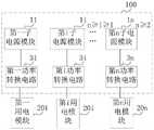
作为示例,请参考图7a,在本申请的一个实施例中提供的一种移动设备电源100中,设置第i子电源模块1i经由第i功率转换电路3i与第i用电模块20i连接,i∈[1,n],n≥2,i为正整数;以根据各所述供电电压范围确定第i用电模块20i对应的第i子电源模块1i,以将第i子电源模块的输出电压幅值,转换为第i用电模块所需的电压幅值,以避免产生因供电电压不匹配导致影响电子元件寿命的情况发生。As an example, please refer to FIG. 7a, in a mobile
作为示例,请参考图7b,在本申请的一个实施例中提供的一种移动设备电源100中,设置第i子电源模块1i经由第i BUCK电路31i与第i用电模块20i连接,i∈[1,n],n≥2,i为正整数;以根据各所述供电电压范围确定第i用电模块20i对应的第i子电源模块1i,以将第i子电源模块的输出电压幅值,转换为第i用电模块所需的电压幅值,以避免产生因供电电压不匹配导致影响电子元件寿命的情况发生。As an example, please refer to FIG. 7b, in a mobile
作为示例,请参考图7c,在本申请的一个实施例中提供的一种移动设备电源100中,设置第i子电源模块1i经由第i低压差线性稳压电路32i与第i用电模块20i连接,i∈[1,n],n≥2,i为正整数;以根据各所述供电电压范围确定第i用电模块20i对应的第i子电源模块1i,以将第i子电源模块的输出电压幅值,转换为第i用电模块所需的电压幅值,以避免产生因供电电压不匹配导致影响电子元件寿命的情况发生。As an example, please refer to FIG. 7c, in a mobile
作为示例,请参考图8,在本申请的一个实施例中,对于一个包括12个需要的供电电压的幅值不同的用电电路来说,可以将这12个用电电路按照所需供电电压的幅值升序排列或降序排列以形成规律序列。若记这12个按照所需供电电压的幅值升序排列的用电电路分别对应的所需供电电压的最大值为v1、v2、v3、……v12,则可以形成升序排列的规律序列a=[v1,v2,v3,……v12];若确定提供4个子电源模块为这12个用电电路供电合适,则可以根据规律序列a确定这4个用电模块的供电电压范围,例如,可以依次设置这4个用电模块的供电电压范围的最大值为V_1、V_2、V_3及V_4,其中,V_1<V_2<V_3<V_4,可以设置v3≦V_1,v6≦V_2,v9≦V_3且v12≦V_4;即,设置供电电压范围的最大值为V_1的第一用电模块包括所需供电电压的最大值分别为v1、v2及v3的三个用电电路,设置供电电压范围的最大值为V_2的第二用电模块包括所需供电电压的最大值分别为v4、v5及v6的三个用电电路,设置供电电压范围的最大值为V_3的第三用电模块包括所需供电电压的最大值分别为v7、v8及v9的三个用电电路,设置供电电压范围的最大值为V_4的第四用电模块包括所需供电电压的最大值分别为v10、v11及v12的三个用电电路;然后利用这4个相互独立的子电源模块形成的移动设备供电电源为这4个用电模块供电。由于提供的子电源模块输出电压的最大值与对应连接的用电模块所需供电电压的最大值相匹配,避免利用输入输出电压差比较大的功率转换器将电源提供的电压升压至移动设备内部的高压用电模块所需的工作电压,从而避免了因该功率转换器的输入输出电压差较大引发的发热问题,提高了电源储能的利用率的同时相对延长了移动设备的待机使用时间。As an example, please refer to FIG. 8. In an embodiment of the present application, for a power supply circuit including 12 required power supply voltages with different amplitudes, the 12 power supply circuits can be set according to the required power supply voltage. The magnitudes are sorted in ascending or descending order to form a regular sequence. If the maximum values of the required power supply voltages corresponding to the 12 power-consuming circuits arranged in ascending order of the required power supply voltage amplitudes are recorded as v1, v2, v3, ... v12, a regular sequence of ascending order can be formed a= [v1,v2,v3,...v12]; If it is determined that it is appropriate to provide 4 sub-power modules to supply power to these 12 power-consuming circuits, the power supply voltage range of these 4 power-consuming modules can be determined according to the regular sequence a. For example, you can Set the maximum value of the power supply voltage range of these four power modules to V_1, V_2, V_3 and V_4 in turn, where V_1<V_2<V_3<V_4, you can set v3≦V_1, v6≦V_2, v9≦V_3 and v12≦ V_4; that is, the first power-consuming module whose maximum value of the power supply voltage range is set to V_1 includes three power-consuming circuits whose maximum values of the required power supply voltage are v1, v2 and v3, respectively, and the maximum value of the power supply voltage range is set to V_2 The second power-consuming module includes three power-consuming circuits whose maximum required power supply voltages are v4, v5 and v6, respectively, and the third power-consuming module whose maximum power supply voltage range is set to V_3 includes the maximum required power supply voltage. The three power-consuming circuits whose values are v7, v8 and v9 respectively, and the fourth power-consuming module whose maximum value of the power supply voltage range is set to V_4 includes three power-consuming circuits whose maximum values of required power supply voltage are v10, v11 and v12 respectively circuit; and then use the mobile device power supply formed by the four mutually independent sub-power modules to supply power to the four power modules. Since the maximum value of the output voltage of the provided sub-power module matches the maximum value of the power supply voltage required by the corresponding connected power module, it is avoided to use a power converter with a large input-output voltage difference to boost the voltage provided by the power supply to the mobile device. The working voltage required by the internal high-voltage power module, thus avoiding the heating problem caused by the large input and output voltage difference of the power converter, improving the utilization rate of power storage, and relatively prolonging the standby use of mobile devices. time.
作为示例,请参考图9,在本申请的一个实施例中,将图8中示意的第j子电源模块1j经由第j BUCK电路31j与第j用电模块20j连接,j∈[1,4],j为正整数;以根据各所述供电电压范围确定第j用电模块20j对应的第j子电源模块1j,以将第j子电源模块的输出电压幅值,转换为第j用电模块所需的电压幅值,以避免产生因供电电压不匹配导致影响电子元件寿命的情况发生。As an example, please refer to FIG. 9, in an embodiment of the present application, the jth sub-power module 1j shown in FIG. 8 is connected to the jth power consumption module 20j via the jth BUCK circuit 31j, j∈[1,4 ], j is a positive integer; to determine the jth sub-power supply module 1j corresponding to the jth power consumption module 20j according to each described supply voltage range, to convert the output voltage amplitude of the jth sub-power module into the jth power consumption The voltage amplitude required by the module to avoid the occurrence of conditions that affect the life of electronic components due to mismatched supply voltages.
进一步地,请参考图10,在本申请的一个实施例中提供的一种移动设备电源中,至少一所述BUCK电路包括第一容性储能单元3111、第一可控开关单元3112、二极管3113、感性储能单元3114及第二容性储能单元3115,第一容性储能单元3111被配置为与一所述子电源模块例如是第一子电源模块11并联;第一可控开关单元3112被配置为第一端口与第一容性储能单元3111的第一端口连接;二极管3113被配置为阴极与第一可控开关单元3112的第二端口连接,且阳极与第一容性储能单元3111的第二端口连接;感性储能单元3114被配置为第一端口与第一可控开关单元3112的第二端口及二极管3113的阴极均连接;第二容性储能单元3115被配置为第一端口与感性储能单元3114的第二端口连接,且第二端口与二极管3113的阳极连接;其中,通过控制第一可控开关单元3112的开关频率及/或开关时间,使得第二容性储能单元3115用于向与其连接的用电模块例如是第一用电模块201提供所需的电压幅值。Further, please refer to FIG. 10 , in a mobile device power supply provided in an embodiment of the present application, at least one of the buck circuits includes a first capacitive
作为示例,请参考图11,在本申请的一个实施例中提供的一种移动设备电源中,至少一所述BUCK电路包括电容C1、第一功率开关管S1、二极管D1、电感L1及电容C2,其中,第一功率开关管S1的第一端口与电容C1的第一端口连接,二极管D1的阴极与第一功率开关管S1的第二端口连接,二极管D1的阳极与电容C1的第二端口连接,电感L与第一功率开关管S1的第二端口、二极管D1的阴极均连接,电容C2的第一端口与电感L的第二端口连接,电容C2的第二端口与二极管D1的阳极连接。请参考图10及图11,可以设置第一子电源模11块并联在电容C1的输入端,并设置第一用电模块201并联在电容C2的输出端。As an example, please refer to FIG. 11. In a mobile device power supply provided in an embodiment of the present application, at least one of the buck circuits includes a capacitor C1, a first power switch S1, a diode D1, an inductor L1 and a capacitor C2 , wherein the first port of the first power switch S1 is connected to the first port of the capacitor C1, the cathode of the diode D1 is connected to the second port of the first power switch S1, and the anode of the diode D1 is connected to the second port of the capacitor C1 The inductor L is connected to the second port of the first power switch S1 and the cathode of the diode D1, the first port of the capacitor C2 is connected to the second port of the inductor L, and the second port of the capacitor C2 is connected to the anode of the diode D1. . Referring to FIG. 10 and FIG. 11 , the first
在本申请的一个实施例中,提供了一种移动设备,包括任一本申请实施例中所述的移动设备电源。该移动设备具备待机时间长、产热低及充电利用率高等优点。In one embodiment of the present application, a mobile device is provided, including a mobile device power supply described in any of the embodiments of the present application. The mobile device has the advantages of long standby time, low heat generation and high charging utilization.
本领域普通技术人员可以理解实现上述实施例方法中的全部或部分流程,是可以通过计算机程序来指令相关的硬件来完成,所述的计算机程序可存储于一非易失性计算机可读取存储介质中,该计算机程序在执行时,可包括如上述各方法的实施例的流程。其中,本申请所提供的各实施例中所使用的对存储器、存储、数据库或其它介质的任何引用,均可包括非易失性和/或易失性存储器。非易失性存储器可包括只读存储器(ROM)、可编程ROM(PROM)、电可编程ROM(EPROM)、电可擦除可编程ROM(EEPROM)或闪存。易失性存储器可包括随机存取存储器(RAM)或者外部高速缓冲存储器。作为说明而非局限,RAM以多种形式可得,诸如静态RAM(SRAM)、动态RAM(DRAM)、同步DRAM(SDRAM)、双数据率SDRAM(DDRSDRAM)、增强型SDRAM(ESDRAM)、同步链路(Synchlink)DRAM(SLDRAM)、存储器总线(Rambus)直接RAM(RDRAM)、直接存储器总线动态RAM(DRDRAM)、以及存储器总线动态RAM(RDRAM)等。Those of ordinary skill in the art can understand that all or part of the processes in the methods of the above embodiments can be implemented by instructing relevant hardware through a computer program, and the computer program can be stored in a non-volatile computer-readable storage In the medium, when the computer program is executed, it may include the processes of the above-mentioned method embodiments. Wherein, any reference to memory, storage, database or other medium used in the various embodiments provided in this application may include non-volatile and/or volatile memory. Nonvolatile memory may include read only memory (ROM), programmable ROM (PROM), electrically programmable ROM (EPROM), electrically erasable programmable ROM (EEPROM), or flash memory. Volatile memory may include random access memory (RAM) or external cache memory. By way of illustration and not limitation, RAM is available in various forms such as static RAM (SRAM), dynamic RAM (DRAM), synchronous DRAM (SDRAM), double data rate SDRAM (DDRSDRAM), enhanced SDRAM (ESDRAM), synchronous chain Road (Synchlink) DRAM (SLDRAM), memory bus (Rambus) direct RAM (RDRAM), direct memory bus dynamic RAM (DRDRAM), and memory bus dynamic RAM (RDRAM), etc.
以上所述实施例的各技术特征可以进行任意的组合,为使描述简洁,未对上述实施例中的各个技术特征所有可能的组合都进行描述,然而,只要这些技术特征的组合不存在矛盾,都应当认为是本说明书记载的范围。The technical features of the above-described embodiments can be combined arbitrarily. For the sake of brevity, all possible combinations of the technical features in the above-described embodiments are not described. However, as long as there is no contradiction between the combinations of these technical features, All should be regarded as the scope described in this specification.
以上所述实施例仅表达了本申请的几种实施方式,其描述较为具体和详细,但并不能因此而理解为对申请专利范围的限制。应当指出的是,对于本领域的普通技术人员来说,在不脱离本申请构思的前提下,还可以做出若干变形和改进,这些都属于本申请的保护范围。因此,本申请专利的保护范围应以所附权利要求为准。The above-mentioned embodiments only represent several embodiments of the present application, and the descriptions thereof are relatively specific and detailed, but should not be construed as a limitation on the scope of the patent application. It should be pointed out that for those skilled in the art, without departing from the concept of the present application, several modifications and improvements can be made, which all belong to the protection scope of the present application. Therefore, the scope of protection of the patent of the present application shall be subject to the appended claims.
Claims (10)
Translated fromChinesePriority Applications (1)
| Application Number | Priority Date | Filing Date | Title |
|---|---|---|---|
| CN202011172623.9ACN114498790A (en) | 2020-10-28 | 2020-10-28 | Mobile device power supply method, mobile device power supply and mobile device |
Applications Claiming Priority (1)
| Application Number | Priority Date | Filing Date | Title |
|---|---|---|---|
| CN202011172623.9ACN114498790A (en) | 2020-10-28 | 2020-10-28 | Mobile device power supply method, mobile device power supply and mobile device |
Publications (1)
| Publication Number | Publication Date |
|---|---|
| CN114498790Atrue CN114498790A (en) | 2022-05-13 |
Family
ID=81491338
Family Applications (1)
| Application Number | Title | Priority Date | Filing Date |
|---|---|---|---|
| CN202011172623.9APendingCN114498790A (en) | 2020-10-28 | 2020-10-28 | Mobile device power supply method, mobile device power supply and mobile device |
Country Status (1)
| Country | Link |
|---|---|
| CN (1) | CN114498790A (en) |
Citations (3)
| Publication number | Priority date | Publication date | Assignee | Title |
|---|---|---|---|---|
| US20080100143A1 (en)* | 2006-11-01 | 2008-05-01 | O2Micro Inc. | Power management system with charger/boost controller |
| CN105281397A (en)* | 2014-06-24 | 2016-01-27 | 苹果公司 | Battery Charging with Reusable Inductor for Boost |
| CN108233699A (en)* | 2017-07-31 | 2018-06-29 | 珠海市魅族科技有限公司 | A kind of power management chip, electric power system and electronic equipment |
- 2020
- 2020-10-28CNCN202011172623.9Apatent/CN114498790A/enactivePending
Patent Citations (3)
| Publication number | Priority date | Publication date | Assignee | Title |
|---|---|---|---|---|
| US20080100143A1 (en)* | 2006-11-01 | 2008-05-01 | O2Micro Inc. | Power management system with charger/boost controller |
| CN105281397A (en)* | 2014-06-24 | 2016-01-27 | 苹果公司 | Battery Charging with Reusable Inductor for Boost |
| CN108233699A (en)* | 2017-07-31 | 2018-06-29 | 珠海市魅族科技有限公司 | A kind of power management chip, electric power system and electronic equipment |
Similar Documents
| Publication | Publication Date | Title |
|---|---|---|
| Athikkal et al. | Performance analysis of novel bridge type dual input DC-DC converters | |
| Lee et al. | Novel droop control of battery energy storage systems based on battery degradation cost in islanded DC microgrids | |
| Zhang et al. | Unique modular structure of multicell high-boost converters with reduced component currents | |
| McClurg et al. | A series-stacked architecture for high-efficiency data center power delivery | |
| Teng et al. | Smart control strategy for conversion efficiency enhancement of parallel inverters at light loads | |
| Pacas et al. | Design of a robust and efficient power electronic interface for the grid integration of solar photovoltaic generation systems | |
| Kesarwani et al. | A multi-level ladder converter supporting vertically-stacked digital voltage domains | |
| Fusheng et al. | Power converters for DC microgrids–modelling and simulation | |
| Sattianadan et al. | Investigation of low voltage DC microgrid using sliding mode control | |
| Bharathidasan et al. | Intelligent Fuzzy Based High Gain Non-Isolated Converter for DC Micro-Grids. | |
| Folmer et al. | 48-V input DC-DC high step-down converter in GaN-based design | |
| Ammous et al. | Energy efficiency of a novel low voltage direct current supply for the future building | |
| Cid-Pastor et al. | Design of photovoltaic-based current sources for maximum power transfer by means of power gyrators | |
| Chakraborty et al. | An enhanced DC-DC boost converter based stand-alone PV-Battery OFF-Grid system with voltage balancing capability for fluctuating environmental and load conditions | |
| Brey et al. | Power conditioning of fuel cell systems in portable applications | |
| Yeates et al. | Quasi-parallel switched-capacitor and regulating PWM DC-DC converter | |
| Jose et al. | Simulation and implementation of superlift Luo converter | |
| CN114498790A (en) | Mobile device power supply method, mobile device power supply and mobile device | |
| Bugueño et al. | Transformerless partial power ac-link step-down converter | |
| Górecki | Voltage regulators for the laptop's power supply station with photovoltaic modules | |
| Patra et al. | Design of Hybrid Energy Storage System Model with Multi-input Converter | |
| Jayananda et al. | Powering 12-V LED luminiaries with supercapacitor-based energy storage in DC-microgrid systems | |
| Naligama et al. | Extending supercapacitor assisted loss management approach for efficiency improvements in solar inverters | |
| PK et al. | Hardware implementation of high efficient and high voltage gain dc-dc converter for dc microgrid applications | |
| Muppalla et al. | Design of Compensator for High Gain DC-DC Converter |
Legal Events
| Date | Code | Title | Description |
|---|---|---|---|
| PB01 | Publication | ||
| PB01 | Publication | ||
| SE01 | Entry into force of request for substantive examination | ||
| SE01 | Entry into force of request for substantive examination |