CN114498643A - A Method for Harmonic Suppression of Grid-connected Current Based on Improved Phase Locked Loop - Google Patents
A Method for Harmonic Suppression of Grid-connected Current Based on Improved Phase Locked LoopDownload PDFInfo
- Publication number
- CN114498643A CN114498643ACN202210086882.2ACN202210086882ACN114498643ACN 114498643 ACN114498643 ACN 114498643ACN 202210086882 ACN202210086882 ACN 202210086882ACN 114498643 ACN114498643 ACN 114498643A
- Authority
- CN
- China
- Prior art keywords
- grid
- phase
- locked loop
- current
- connected current
- Prior art date
- Legal status (The legal status is an assumption and is not a legal conclusion. Google has not performed a legal analysis and makes no representation as to the accuracy of the status listed.)
- Granted
Links
Images


Classifications
- H—ELECTRICITY
- H02—GENERATION; CONVERSION OR DISTRIBUTION OF ELECTRIC POWER
- H02J—CIRCUIT ARRANGEMENTS OR SYSTEMS FOR SUPPLYING OR DISTRIBUTING ELECTRIC POWER; SYSTEMS FOR STORING ELECTRIC ENERGY
- H02J3/00—Circuit arrangements for AC mains or AC distribution networks
- H02J3/01—Arrangements for reducing harmonics or ripples
- H—ELECTRICITY
- H02—GENERATION; CONVERSION OR DISTRIBUTION OF ELECTRIC POWER
- H02J—CIRCUIT ARRANGEMENTS OR SYSTEMS FOR SUPPLYING OR DISTRIBUTING ELECTRIC POWER; SYSTEMS FOR STORING ELECTRIC ENERGY
- H02J3/00—Circuit arrangements for AC mains or AC distribution networks
- H02J3/38—Arrangements for parallely feeding a single network by two or more generators, converters or transformers
- H—ELECTRICITY
- H02—GENERATION; CONVERSION OR DISTRIBUTION OF ELECTRIC POWER
- H02M—APPARATUS FOR CONVERSION BETWEEN AC AND AC, BETWEEN AC AND DC, OR BETWEEN DC AND DC, AND FOR USE WITH MAINS OR SIMILAR POWER SUPPLY SYSTEMS; CONVERSION OF DC OR AC INPUT POWER INTO SURGE OUTPUT POWER; CONTROL OR REGULATION THEREOF
- H02M1/00—Details of apparatus for conversion
- H02M1/12—Arrangements for reducing harmonics from AC input or output
- H—ELECTRICITY
- H02—GENERATION; CONVERSION OR DISTRIBUTION OF ELECTRIC POWER
- H02M—APPARATUS FOR CONVERSION BETWEEN AC AND AC, BETWEEN AC AND DC, OR BETWEEN DC AND DC, AND FOR USE WITH MAINS OR SIMILAR POWER SUPPLY SYSTEMS; CONVERSION OF DC OR AC INPUT POWER INTO SURGE OUTPUT POWER; CONTROL OR REGULATION THEREOF
- H02M7/00—Conversion of AC power input into DC power output; Conversion of DC power input into AC power output
- H02M7/42—Conversion of DC power input into AC power output without possibility of reversal
- H02M7/44—Conversion of DC power input into AC power output without possibility of reversal by static converters
- H02M7/48—Conversion of DC power input into AC power output without possibility of reversal by static converters using discharge tubes with control electrode or semiconductor devices with control electrode
- H02M7/493—Conversion of DC power input into AC power output without possibility of reversal by static converters using discharge tubes with control electrode or semiconductor devices with control electrode the static converters being arranged for operation in parallel
- H—ELECTRICITY
- H02—GENERATION; CONVERSION OR DISTRIBUTION OF ELECTRIC POWER
- H02M—APPARATUS FOR CONVERSION BETWEEN AC AND AC, BETWEEN AC AND DC, OR BETWEEN DC AND DC, AND FOR USE WITH MAINS OR SIMILAR POWER SUPPLY SYSTEMS; CONVERSION OF DC OR AC INPUT POWER INTO SURGE OUTPUT POWER; CONTROL OR REGULATION THEREOF
- H02M7/00—Conversion of AC power input into DC power output; Conversion of DC power input into AC power output
- H02M7/42—Conversion of DC power input into AC power output without possibility of reversal
- H02M7/44—Conversion of DC power input into AC power output without possibility of reversal by static converters
- H02M7/48—Conversion of DC power input into AC power output without possibility of reversal by static converters using discharge tubes with control electrode or semiconductor devices with control electrode
- H02M7/53—Conversion of DC power input into AC power output without possibility of reversal by static converters using discharge tubes with control electrode or semiconductor devices with control electrode using devices of a triode or transistor type requiring continuous application of a control signal
- H02M7/537—Conversion of DC power input into AC power output without possibility of reversal by static converters using discharge tubes with control electrode or semiconductor devices with control electrode using devices of a triode or transistor type requiring continuous application of a control signal using semiconductor devices only, e.g. single switched pulse inverters
- H02M7/5387—Conversion of DC power input into AC power output without possibility of reversal by static converters using discharge tubes with control electrode or semiconductor devices with control electrode using devices of a triode or transistor type requiring continuous application of a control signal using semiconductor devices only, e.g. single switched pulse inverters in a bridge configuration
- H02M7/53871—Conversion of DC power input into AC power output without possibility of reversal by static converters using discharge tubes with control electrode or semiconductor devices with control electrode using devices of a triode or transistor type requiring continuous application of a control signal using semiconductor devices only, e.g. single switched pulse inverters in a bridge configuration with automatic control of output voltage or current
- H02M7/53873—Conversion of DC power input into AC power output without possibility of reversal by static converters using discharge tubes with control electrode or semiconductor devices with control electrode using devices of a triode or transistor type requiring continuous application of a control signal using semiconductor devices only, e.g. single switched pulse inverters in a bridge configuration with automatic control of output voltage or current with digital control
- Y—GENERAL TAGGING OF NEW TECHNOLOGICAL DEVELOPMENTS; GENERAL TAGGING OF CROSS-SECTIONAL TECHNOLOGIES SPANNING OVER SEVERAL SECTIONS OF THE IPC; TECHNICAL SUBJECTS COVERED BY FORMER USPC CROSS-REFERENCE ART COLLECTIONS [XRACs] AND DIGESTS
- Y02—TECHNOLOGIES OR APPLICATIONS FOR MITIGATION OR ADAPTATION AGAINST CLIMATE CHANGE
- Y02E—REDUCTION OF GREENHOUSE GAS [GHG] EMISSIONS, RELATED TO ENERGY GENERATION, TRANSMISSION OR DISTRIBUTION
- Y02E40/00—Technologies for an efficient electrical power generation, transmission or distribution
- Y02E40/40—Arrangements for reducing harmonics
Landscapes
- Engineering & Computer Science (AREA)
- Power Engineering (AREA)
- Inverter Devices (AREA)
Abstract
Description
Translated fromChinese技术领域technical field
本发明涉及电力技术领域,尤其涉及一种基于改进锁相环的并网电流谐波抑制的方法。The invention relates to the field of electric power technology, in particular to a method for suppressing harmonics of grid-connected current based on an improved phase-locked loop.
背景技术Background technique
电力与国家经济和人民生活息息相关,供电安全更是国家安全战略和国民经济社会发展的重要方面。在生态环境不断恶化、民众环保意识日渐提高、新能源技术不断发展等的大趋势下,构建环保、可靠、高效的现代化电力能源网络是十分必要的。可再生能源发电系统具有能效利用合理、损耗小、污染少、运行灵活、系统经济性好等特点,发展潜力巨大,一直是国内外关注的热点。但是,这些可再生能源系统同时也具有容量小,分布广,交直流兼有,且电压或频率波动性大等弊端。如何稳定、可靠地将这些可再生能源系统并网,融入到电力系统中是我们目前所面临的一项关键问题,并网逆变器作为分散式可再生能源接入配电网的重要接口,在光伏并网发电系统中起着至关重要的作用,随着分布式可再生能源渗透率的不断提高,并网逆变器在传统配电网中的地位越发突出,因此成为了人们关注的热点技术之一。Electricity is closely related to the national economy and people's life, and power supply security is an important aspect of national security strategy and national economic and social development. Under the general trend of deteriorating ecological environment, increasing public awareness of environmental protection, and continuous development of new energy technologies, it is very necessary to build an environmentally friendly, reliable and efficient modern power energy network. The renewable energy power generation system has the characteristics of reasonable utilization of energy efficiency, small loss, less pollution, flexible operation, and good system economy. However, these renewable energy systems also have the disadvantages of small capacity, wide distribution, both AC and DC, and large voltage or frequency fluctuations. How to stably and reliably connect these renewable energy systems to the grid and integrate them into the power system is a key issue we are currently facing. It plays a vital role in the photovoltaic grid-connected power generation system. With the continuous improvement of the penetration rate of distributed renewable energy, the status of grid-connected inverters in the traditional distribution network has become more and more prominent, so it has become a focus of attention. One of the hottest technologies.
作为连接分布式新能源发电系统与大电网之间的桥梁,并网逆变器的运行状态与控制性能对微电网稳定运行与并网电能质量起至关重要的作用。逆变器的控制性能主要由逆变器主电路拓扑结构、控制结构及控制策略决定,只有选用合适的拓扑结构并配合相应的控制技术,才能高效地把新能源电源产生的直流电量电能转化为符合微电网内用户用电设备需求,同时又符合电力系统并网电能质量要求的交流电能,实现满足本地负载用电需求的同时,将多产生的电能送入大电网的目标。并网逆变器的拓扑结构对新能源并网系统的建造、维护成本、电能转换效率与控制性能等指标具有重大意义,是新能源并网系统的核心环节。As a bridge between the distributed new energy power generation system and the large power grid, the operating state and control performance of the grid-connected inverter play a crucial role in the stable operation of the micro-grid and the quality of the grid-connected power. The control performance of the inverter is mainly determined by the inverter main circuit topology, control structure and control strategy. Only by selecting the appropriate topology structure and cooperating with the corresponding control technology, can the DC power generated by the new energy power source be efficiently converted into electricity. The AC power that meets the needs of users' electrical equipment in the microgrid and at the same time meets the power quality requirements of the grid-connected power system to achieve the goal of meeting the power demand of local loads and feeding the more generated power into the large power grid. The topology of the grid-connected inverter is of great significance to the construction, maintenance cost, power conversion efficiency and control performance of the new energy grid-connected system, and is the core link of the new energy grid-connected system.
现今,无论是PQ型并网逆变器还是DCVQ型并网逆变器都仍然需要追踪电网的频率和相位来与大电网保持同步,从而保证良好的并网电能质量。目前广泛使用锁相环(phase-locked loop,PLL)作为与电网的同步单元,因此并网逆变器系统的控制性能主要取决于PLL对电网频率和相位的准确追踪。在电网阻抗小到可以忽略的强电网情况下,PLL能稳定的工作并且能够准确提供电网电压信息供控制回路使用。Today, both the PQ grid-connected inverter and the DCVQ grid-connected inverter still need to track the frequency and phase of the grid to keep pace with the large grid, so as to ensure good grid-connected power quality. At present, a phase-locked loop (PLL) is widely used as the synchronization unit with the power grid, so the control performance of the grid-connected inverter system mainly depends on the accurate tracking of the frequency and phase of the power grid by the PLL. In the case of a strong grid where the grid impedance is negligibly small, the PLL can work stably and can accurately provide grid voltage information for the control loop to use.
但是我国的风光清洁能源主要位于西北等地区,由于远离重负荷区,目前分布式发电系统广泛使用较为经济的集中发电,远距离输电模式。这种远距离输电模式会给电网引入较大的线路阻抗,使大电网对于分布式发电系统来说呈现弱电网特性。而PWM控制会在并网逆变器与大电网的公共耦合点(point of common coupling,PCC)产生谐波电压,这种情况下弱电网的高电网阻抗特性会使PCC点电压出现谐波共振和波形畸变。如果不加以控制,畸变的PCC电压又会使并网逆变器的同步单元PLL出现偏差甚至失效,进一步恶化并网电能质量,导致出现系统失稳的现象。同时随着PLL带宽的增加这种不稳定现象逐渐加剧。而现有的针对PLL的一系列改进措施在不同的电网环境下需要对同步单元进行调整,增加了控制系统的复杂程度。并且在不同的电网环境下需要对控制系统的结构进行调整,不具有普适性。However, my country's wind-solar clean energy is mainly located in the northwest and other regions. Because it is far away from the heavy-load area, the distributed power generation system widely uses the more economical centralized power generation and long-distance power transmission mode. This long-distance power transmission mode will introduce large line impedance to the power grid, making the large power grid appear weak grid characteristics for the distributed generation system. The PWM control will generate harmonic voltage at the point of common coupling (PCC) between the grid-connected inverter and the large grid. In this case, the high grid impedance characteristics of the weak grid will cause harmonic resonance in the voltage at the PCC point. and waveform distortion. If not controlled, the distorted PCC voltage will cause deviation or even failure of the synchronization unit PLL of the grid-connected inverter, further deteriorating the grid-connected power quality, and causing system instability. At the same time, with the increase of PLL bandwidth, this instability phenomenon gradually intensifies. However, the existing series of improvement measures for PLL need to adjust the synchronization unit under different power grid environments, which increases the complexity of the control system. In addition, the structure of the control system needs to be adjusted in different power grid environments, which is not universal.
针对弱电网下PLL给并网逆变器稳定性带来的负面影响以及一系列改进措施的复杂程度,如果能去除PLL环节就能够从根本上解决该问题。而现有的去除PLL但是却引入例如锁频环等其他的同步单元的做法会带来和PLL一样的问题。因此考虑将研究的重点改为利用并网逆变器的控制策略来实现自同步,这具有现实的意义。In view of the negative impact of PLL on the stability of grid-connected inverters in weak grids and the complexity of a series of improvement measures, the problem can be fundamentally solved if the PLL link can be removed. The existing practice of removing the PLL but introducing other synchronization units such as a frequency-locked loop will bring about the same problems as the PLL. Therefore, it is of practical significance to consider changing the research focus to using the control strategy of grid-connected inverters to achieve self-synchronization.
发明内容SUMMARY OF THE INVENTION
本部分的目的在于概述本发明的实施例的一些方面以及简要介绍一些较佳实施例。在本部分以及本申请的说明书摘要和发明名称中可能会做些简化或省略以避免使本部分、说明书摘要和发明名称的目的模糊,而这种简化或省略不能用于限制本发明的范围。The purpose of this section is to outline some aspects of embodiments of the invention and to briefly introduce some preferred embodiments. Some simplifications or omissions may be made in this section and the abstract and title of the application to avoid obscuring the purpose of this section, abstract and title, and such simplifications or omissions may not be used to limit the scope of the invention.
鉴于上述现有存在的问题,提出了本发明。The present invention has been proposed in view of the above-mentioned existing problems.
因此,本发明解决的技术问题是:弱电网的高电网阻抗特性会使PCC点电压出现谐波共振和波形畸变,导致出现系统失稳的问题。Therefore, the technical problem solved by the present invention is: the high power grid impedance characteristic of the weak power grid will cause harmonic resonance and waveform distortion in the PCC point voltage, resulting in the problem of system instability.
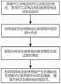
为解决上述技术问题,本发明提供如下技术方案:包括,采集并网逆变器系统公共耦合点(PCC点)电压和所述PCC点电压的相位,并将所述PCC点电压相位前馈至电流控制回路中;对传统的同步旋转坐标系锁相环结构进行改进;获取并网变压器系统的数学模型及输出阻抗模型;利用电网电流前馈控制产生的调制信号控制VSC各桥臂中IGBT的通断,提高并网逆变器系统的稳定性。In order to solve the above technical problems, the present invention provides the following technical solutions: including collecting the voltage at the point of common coupling (PCC point) of the grid-connected inverter system and the phase of the voltage at the PCC point, and feeding the phase of the voltage at the PCC point forward to the grid-connected inverter system. In the current control loop; improve the traditional synchronous rotating coordinate system phase-locked loop structure; obtain the mathematical model and output impedance model of the grid-connected transformer system; use the modulation signal generated by the grid current feedforward control to control the IGBT in each bridge arm of the VSC. On-off, improve the stability of the grid-connected inverter system.
作为本发明所述的基于改进锁相环的并网电流谐波抑制的方法的一种优选方案,其中:采用电压传感器测量并网逆变器系统公共耦合点(PCC点)电压,利用锁相环采集所述PCC点电压的相位。As a preferred solution of the method for reducing the harmonics of grid-connected current based on the improved phase-locked loop of the present invention, wherein: a voltage sensor is used to measure the voltage of the point of common coupling (PCC point) of the grid-connected inverter system, and the phase-locked The loop acquires the phase of the PCC point voltage.
作为本发明所述的基于改进锁相环的并网电流谐波抑制的方法的一种优选方案,其中:对传统的同步旋转坐标系锁相环结构进行改进包括,在所述锁相环结构环路滤波通道中设计一种低通滤波器。As a preferred solution of the method for improving the harmonic suppression of grid-connected current based on the phase-locked loop described in the present invention, wherein: the improvement of the traditional synchronous rotation coordinate system phase-locked loop structure includes, in the phase-locked loop structure A low-pass filter is designed in the loop filter channel.
作为本发明所述的基于改进锁相环的并网电流谐波抑制的方法的一种优选方案,其中:所述滤波器H(s)包括,As a preferred solution of the method for improving the harmonic suppression of grid-connected current based on the phase-locked loop of the present invention, wherein: the filter H(s) includes:

其中,π表示圆周率,kf表示增益系数,Pf=RC,R表示电阻,C表示电容。Among them, π represents the circle ratio, kf represents the gain coefficient, Pf =RC, R represents the resistance, and C represents the capacitance.
作为本发明所述的基于改进锁相环的并网电流谐波抑制的方法的一种优选方案,其中:改进后的锁相环结构的传递函数GPLL(s)包括,As a preferred solution of the method for suppressing harmonics of grid-connected current based on an improved phase-locked loop according to the present invention, wherein: the transfer function GPLL (s) of the improved phase-locked loop structure includes:

其中,π表示圆周率,kf表示增益系数,Pf=RC,R表示电阻,C表示电容,Um表示PCC点电压幅值。Among them, π represents the circle ratio, kf represents the gain coefficient, Pf =RC, R represents the resistance, C represents the capacitance, and Um represents the voltage amplitude of the PCC point.
作为本发明所述的基于改进锁相环的并网电流谐波抑制的方法的一种优选方案,其中:根据并网逆变器系统的控制结构图得到控制系统的数学模型,由所述控制系统的数学模型得到系统的输出阻抗模型。As a preferred solution of the method for improving the grid-connected current harmonic suppression based on the phase-locked loop of the present invention, wherein: the mathematical model of the control system is obtained according to the control structure diagram of the grid-connected inverter system, and the control system is controlled by the control system. The mathematical model of the system yields the output impedance model of the system.
作为本发明所述的基于改进锁相环的并网电流谐波抑制的方法的一种优选方案,其中:所述输出阻抗系统模型包括,As a preferred solution of the method for improving the harmonic suppression of grid-connected current based on the phase-locked loop of the present invention, wherein: the output impedance system model includes:
利用所述并网逆变器控制系统的数学模型获取并网电流ig;Obtain the grid-connected current ig by using the mathematical model of the grid-connected inverter control system;
基于所述PCC点电压、并网电流参考电流幅值Iref和改进后的锁相环结构的传递函数GPLL(s)获取并网电流控制的基准电流iref。The grid-connected current control reference current iref is obtained based on the PCC point voltage, the grid-connected current reference current amplitude Iref and the transfer function GPLL (s) of the improved phase-locked loop structure.
作为本发明所述的基于改进锁相环的并网电流谐波抑制的方法的一种优选方案,其中:所述并网电流ig包括,As a preferred solution of the method for improving the harmonic suppression of grid-connected current based on the phase-locked loop of the present invention, wherein: the grid-connected current ig includes:

其中,Lf表示滤波电感,KPWM表示脉冲调制增益系数,Gi(s)表示并网电流控制器,Gde(s)表示数字控制延时的传递函数,UPCC表示PCC点电压,iref表示并网电流控制的基准电流。Among them, Lf is the filter inductance, KPWM is the pulse modulation gain coefficient, Gi (s) is the grid-connected current controller, Gde (s) is the transfer function of the digital control delay, UPCC is the PCC point voltage, iref represents the reference current for grid-connected current control.
作为本发明所述的基于改进锁相环的并网电流谐波抑制的方法的一种优选方案,其中:所述基准电流iref包括,As a preferred solution of the method for improving the harmonic suppression of grid-connected current based on the phase-locked loop of the present invention, wherein: the reference current iref includes:
iref=IrefUPCCGPLL(s)iref =Iref UPCC GPLL (s)
其中,,Iref表示并网电流参考电流幅值,UPCC表示PCC点电压,GPLL(s)表示改进后的锁相环结构的传递函数。Among them, Iref represents the grid-connected current reference current amplitude, UPCC represents the PCC point voltage, and GPLL (s) represents the transfer function of the improved phase-locked loop structure.
作为本发明所述的基于改进锁相环的并网电流谐波抑制的方法的一种优选方案,其中:基于所述并网电流ig和所述基准电流iref,获取锁相环时逆变器等效输出阻抗Zout_PLL,As a preferred solution of the method for improving the harmonic suppression of grid-connected current based on the phase-locked loop of the present invention, wherein: based on the grid-connected current ig and the reference current iref , the time inverse of the phase-locked loop is obtained The inverter equivalent output impedance Zout_PLL ,

其中,Lf表示滤波电感,KPWM表示脉冲调制增益系数,Gi(s)表示并网电流控制器,Gde(s)表示数字控制延时的传递函数,Iref表示并网电流参考电流幅值,GPLL(s)表示改进后的锁相环结构的传递函数。Among them, Lf is the filter inductor, KPWM is the pulse modulation gain coefficient, Gi (s) is the grid-connected current controller, Gde (s) is the transfer function of the digital control delay, and Iref is the grid-connected current reference current Amplitude, GPLL (s) represents the transfer function of the improved phase-locked loop structure.
本发明的有益效果:本发明设计了一种基于改进锁相环的并网电流谐波抑制的方法,不仅能减小锁相环对并网逆变器的负面影响,提高并网逆变器系统的稳定性,还可以一直并网电流谐波。Beneficial effects of the present invention: The present invention designs a method for suppressing the grid-connected current harmonics based on an improved phase-locked loop, which can not only reduce the negative impact of the phase-locked loop on the grid-connected inverter, but also improve the grid-connected inverter. The stability of the system can also be connected to the grid current harmonics all the time.
附图说明Description of drawings
为了更清楚地说明本发明实施例的技术方案,下面将对实施例描述中所需要使用的附图作简单地介绍,显而易见地,下面描述中的附图仅仅是本发明的一些实施例,对于本领域普通技术人员来讲,在不付出创造性劳动性的前提下,还可以根据这些附图获得其它的附图。其中:In order to illustrate the technical solutions of the embodiments of the present invention more clearly, the following briefly introduces the accompanying drawings used in the description of the embodiments. Obviously, the drawings in the following description are only some embodiments of the present invention. For those of ordinary skill in the art, other drawings can also be obtained based on these drawings without any creative effort. in:
图1为本发明一个实施例提供的一种基于改进锁相环的并网电流谐波抑制的方法的基本流程示意图;FIG. 1 is a basic flowchart of a method for suppressing harmonics of grid-connected current based on an improved phase-locked loop provided by an embodiment of the present invention;
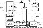
图2为本发明一个实施例提供的一种基于改进锁相环的并网电流谐波抑制的方法的并网逆变器系统的控制结构图;2 is a control structure diagram of a grid-connected inverter system based on a method for improving the grid-connected current harmonic suppression method of a phase-locked loop provided by an embodiment of the present invention;
图3为本发明一个实施例提供的一种基于改进锁相环的并网电流谐波抑制的方法的并网逆变器控制系统的数学模型;FIG. 3 is a mathematical model of a grid-connected inverter control system based on a method for improving the grid-connected current harmonic suppression of a phase-locked loop provided by an embodiment of the present invention;
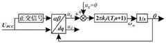
图4为本发明一个实施例提供的一种基于改进锁相环的并网电流谐波抑制的方法的同步旋转坐标系的锁相环的结构图;FIG. 4 is a structural diagram of a phase-locked loop of a synchronous rotating coordinate system based on a method for improving the harmonic suppression of grid-connected current of a phase-locked loop provided by an embodiment of the present invention;
图5为本发明一个实施例提供的一种基于改进锁相环的并网电流谐波抑制的方法的改进后的锁相环结构图;5 is a structural diagram of an improved phase-locked loop based on a method for suppressing harmonics of grid-connected current based on an improved phase-locked loop provided by an embodiment of the present invention;
图6为本发明一个实施例提供的一种基于改进锁相环的并网电流谐波抑制的方法的采用传统锁相环的控制策略的THD柱形图;6 is a THD histogram of a control strategy using a traditional phase-locked loop based on a method for improving the grid-connected current harmonic suppression of the phase-locked loop provided by an embodiment of the present invention;
图7为本发明一个实施例提供的一种基于改进锁相环的并网电流谐波抑制的方法的采用本文所提改进后的锁相环的THD柱形图;FIG. 7 is a THD histogram of a method for suppressing grid-connected current harmonics based on an improved phase-locked loop provided by an embodiment of the present invention using the improved phase-locked loop proposed in this paper;
图8为本发明一个实施例提供的一种基于改进锁相环的并网电流谐波抑制的方法的采用不同锁相环结构时逆变器输出阻抗伯德图;FIG. 8 is a Bode diagram of inverter output impedance when different phase-locked loop structures are adopted based on a method for improving grid-connected current harmonic suppression based on a phase-locked loop provided by an embodiment of the present invention;
图9为本发明一个实施例提供的一种基于改进锁相环的并网电流谐波抑制的方法的采用不同锁相环时并网电流io的仿真波形图。FIG. 9 is a simulation waveform diagram of the grid-connected current io when different phase-locked loops are adopted in a method for improving the harmonic suppression of grid-connected current based on the phase-locked loop provided by an embodiment of the present invention.
具体实施方式Detailed ways
为使本发明的上述目的、特征和优点能够更加明显易懂,下面结合说明书附图对本发明的具体实施方式做详细的说明,显然所描述的实施例是本发明的一部分实施例,而不是全部实施例。基于本发明中的实施例,本领域普通人员在没有做出创造性劳动前提下所获得的所有其他实施例,都应当属于本发明的保护的范围。In order to make the above objects, features and advantages of the present invention more obvious and easy to understand, the specific embodiments of the present invention will be described in detail below with reference to the accompanying drawings. Obviously, the described embodiments are part of the embodiments of the present invention, not all of them. Example. Based on the embodiments of the present invention, all other embodiments obtained by persons of ordinary skill in the art without creative efforts shall fall within the protection scope of the present invention.
在下面的描述中阐述了很多具体细节以便于充分理解本发明,但是本发明还可以采用其他不同于在此描述的其它方式来实施,本领域技术人员可以在不违背本发明内涵的情况下做类似推广,因此本发明不受下面公开的具体实施例的限制。Many specific details are set forth in the following description to facilitate a full understanding of the present invention, but the present invention can also be implemented in other ways different from those described herein, and those skilled in the art can do so without departing from the connotation of the present invention. Similar promotion, therefore, the present invention is not limited by the specific embodiments disclosed below.
其次,此处所称的“一个实施例”或“实施例”是指可包含于本发明至少一个实现方式中的特定特征、结构或特性。在本说明书中不同地方出现的“在一个实施例中”并非均指同一个实施例,也不是单独的或选择性的与其他实施例互相排斥的实施例。Second, reference herein to "one embodiment" or "an embodiment" refers to a particular feature, structure, or characteristic that may be included in at least one implementation of the present invention. The appearances of "in one embodiment" in various places in this specification are not all referring to the same embodiment, nor are they separate or selectively mutually exclusive from other embodiments.
本发明结合示意图进行详细描述,在详述本发明实施例时,为便于说明,表示器件结构的剖面图会不依一般比例作局部放大,而且所述示意图只是示例,其在此不应限制本发明保护的范围。此外,在实际制作中应包含长度、宽度及深度的三维空间尺寸。The present invention is described in detail with reference to the schematic diagrams. When describing the embodiments of the present invention in detail, for the convenience of explanation, the sectional views showing the device structure will not be partially enlarged according to the general scale, and the schematic diagrams are only examples, which should not limit the present invention. scope of protection. In addition, the three-dimensional spatial dimensions of length, width and depth should be included in the actual production.
同时在本发明的描述中,需要说明的是,术语中的“上、下、内和外”等指示的方位或位置关系为基于附图所示的方位或位置关系,仅是为了便于描述本发明和简化描述,而不是指示或暗示所指的装置或元件必须具有特定的方位、以特定的方位构造和操作,因此不能理解为对本发明的限制。此外,术语“第一、第二或第三”仅用于描述目的,而不能理解为指示或暗示相对重要性。At the same time, in the description of the present invention, it should be noted that the orientation or positional relationship indicated in terms such as "upper, lower, inner and outer" is based on the orientation or positional relationship shown in the accompanying drawings, which is only for the convenience of describing the present invention. The invention and simplified description do not indicate or imply that the device or element referred to must have a particular orientation, be constructed and operate in a particular orientation, and therefore should not be construed as limiting the invention. Furthermore, the terms "first, second or third" are used for descriptive purposes only and should not be construed to indicate or imply relative importance.
本发明中除非另有明确的规定和限定,术语“安装、相连、连接”应做广义理解,例如:可以是固定连接、可拆卸连接或一体式连接;同样可以是机械连接、电连接或直接连接,也可以通过中间媒介间接相连,也可以是两个元件内部的连通。对于本领域的普通技术人员而言,可以具体情况理解上述术语在本发明中的具体含义。Unless otherwise expressly specified and limited in the present invention, the term "installation, connection, connection" should be understood in a broad sense, for example: it may be a fixed connection, a detachable connection or an integral connection; it may also be a mechanical connection, an electrical connection or a direct connection. The connection can also be indirectly connected through an intermediate medium, or it can be the internal communication between two elements. For those of ordinary skill in the art, the specific meanings of the above terms in the present invention can be understood in specific situations.
实施例1Example 1
参照图1至图5,为本发明的一个实施例,提供了一种基于改进锁相环的并网电流谐波抑制的方法,包括:1 to 5 , which is an embodiment of the present invention, a method for suppressing harmonics of grid-connected current based on an improved phase-locked loop is provided, including:
S1:采集并网逆变器系统公共耦合点(PCC点)电压和PCC点电压的相位,并将PCC点电压相位前馈至电流控制回路中。需要说明的是:S1: Collect the voltage at the common coupling point (PCC point) of the grid-connected inverter system and the phase of the voltage at the PCC point, and feed forward the phase of the voltage at the PCC point into the current control loop. It should be noted:
采用电压传感器测量并网逆变器系统公共耦合点(PCC点)电压,利用锁相环采集PCC点电压的相位。A voltage sensor is used to measure the voltage at the common coupling point (PCC point) of the grid-connected inverter system, and a phase-locked loop is used to collect the phase of the PCC point voltage.
S2:对传统的同步旋转坐标系锁相环结构进行改进。需要说明的是:S2: Improve the traditional synchronous rotating coordinate system phase-locked loop structure. It should be noted:
对传统的同步旋转坐标系锁相环结构进行改进包括,在锁相环结构环路滤波通道中设计一种低通滤波器对并网逆变器系统是阻抗特性进行重塑,同步旋转坐标系的锁相环的结构图如图4所示,改进后的锁相环结构图如图5所示。The improvement of the traditional synchronous rotating coordinate system phase-locked loop structure includes designing a low-pass filter in the loop filtering channel of the phase-locked loop structure to reshape the impedance characteristics of the grid-connected inverter system, and synchronously rotating the coordinate system. The structure diagram of the phase-locked loop is shown in Figure 4, and the structure diagram of the improved phase-locked loop is shown in Figure 5.
滤波器H(s)包括,The filter H(s) includes,

其中,π表示圆周率,kf表示增益系数,Pf=RC,R表示电阻,C表示电容。Among them, π represents the circle ratio, kf represents the gain coefficient, Pf =RC, R represents the resistance, and C represents the capacitance.
改进后的锁相环结构的传递函数GPLL(s)包括,The transfer function GPLL (s) of the improved phase-locked loop structure includes,

其中,π表示圆周率,kf表示增益系数,Pf=RC,R表示电阻,C表示电容,Um表示PCC点电压幅值。Among them, π represents the circle ratio, kf represents the gain coefficient, Pf =RC, R represents the resistance, C represents the capacitance, and Um represents the voltage amplitude of the PCC point.
S3:获取并网变压器系统的数学模型及输出阻抗模型。需要说明的是:S3: Obtain the mathematical model and output impedance model of the grid-connected transformer system. It should be noted:
根据并网逆变器系统的控制结构图(如图2所示)得到控制系统的数学模型(如图3所示),由控制系统的数学模型得到系统的输出阻抗模型。According to the control structure diagram of the grid-connected inverter system (as shown in Figure 2), the mathematical model of the control system (as shown in Figure 3) is obtained, and the output impedance model of the system is obtained from the mathematical model of the control system.
输出阻抗系统模型包括,The output impedance system model includes,
利用并网逆变器控制系统的数学模型获取并网电流ig;Obtain the grid-connected current ig by using the mathematical model of the grid-connected inverter control system;
当考虑锁相环的影响时,iref不再是一个独立的量,可以用UPCC表示,基于PCC点电压、并网电流参考电流幅值Iref和改进后的锁相环结构的传递函数GPLL(s)获取并网电流控制的基准电流iref。When considering the influence of PLL, iref is no longer an independent quantity and can be represented by UPCC , which is based on the PCC point voltage, the grid-connected current reference current amplitude Iref and the transfer function of the improved PLL structure The GPLL (s) obtains the reference current iref for grid current control.
并网电流ig包括,The grid-connected current ig includes,

其中,Lf表示滤波电感,KPWM表示脉冲调制增益系数,Gi(s)表示并网电流控制器,Gde(s)表示数字控制延时的传递函数,UPCC表示PCC点电压,iref表示并网电流控制的基准电流。Among them, Lf is the filter inductance, KPWM is the pulse modulation gain coefficient, Gi (s) is the grid-connected current controller, Gde (s) is the transfer function of the digital control delay, UPCC is the PCC point voltage, iref represents the reference current for grid-connected current control.
基准电流iref包括,The reference current iref includes,
iref=IrefUPCCGPLL(s)iref =Iref UPCC GPLL (s)
其中,,Iref表示并网电流参考电流幅值,UPCC表示PCC点电压,GPLL(s)表示改进后的锁相环结构的传递函数。Among them, Iref represents the grid-connected current reference current amplitude, UPCC represents the PCC point voltage, and GPLL (s) represents the transfer function of the improved phase-locked loop structure.
基于并网电流ig和基准电流iref,获取锁相环时逆变器等效输出阻抗Zout_PLL,Based on the grid-connected current ig and the reference current iref , the equivalent output impedance Zout_PLL of the inverter when the phase-locked loop is obtained,

其中,Lf表示滤波电感,KPWM表示脉冲调制增益系数,Gi(s)表示并网电流控制器,Gde(s)表示数字控制延时的传递函数,Iref表示并网电流参考电流幅值,GPLL(s)表示改进后的锁相环结构的传递函数。Among them, Lf is the filter inductor, KPWM is the pulse modulation gain coefficient, Gi (s) is the grid-connected current controller, Gde (s) is the transfer function of the digital control delay, and Iref is the grid-connected current reference current Amplitude, GPLL (s) represents the transfer function of the improved phase-locked loop structure.
S4:利用电网电流前馈控制产生的调制信号控制VSC各桥臂中IGBT的通断,提高并网逆变器系统的稳定性。需要说明的是:S4: The modulation signal generated by the grid current feedforward control is used to control the on-off of the IGBTs in each bridge arm of the VSC, so as to improve the stability of the grid-connected inverter system. It should be noted:
主电路拓扑结构由电压源型换流器运行的电路构成,其结构包括整流器(VSC)、直流线路、以及交流滤波器组成,电压源换流器采用的是三相两电平VSC(电压源换流器),每一相都包括上下两个桥臂,共六个桥臂,每个桥臂由绝缘栅双极性晶体管(IGBT)和二极管并联构成,控制电路主要是由电网电流反馈构成的电流控制回路,交流滤波器采用L型滤波器。The main circuit topology is composed of a circuit operated by a voltage source converter. Its structure includes a rectifier (VSC), a DC line, and an AC filter. The voltage source converter uses a three-phase two-level VSC (voltage source). Inverter), each phase includes two upper and lower bridge arms, a total of six bridge arms, each bridge arm is composed of an insulated gate bipolar transistor (IGBT) and a diode in parallel, and the control circuit is mainly composed of grid current feedback The current control loop, the AC filter adopts L-type filter.
本发明设计了一种基于改进锁相环的并网电流谐波抑制的方法,交流滤波器采用L型滤波器,从而避免了LCL逆变器固有的谐振,保证了逆变器拓扑水平上的系统稳定性;利用基于阻抗重塑的新能源发电系统并网逆变器控制方法,通过改进锁相环结构来提高系统的相角裕度,简单有效。The invention designs a method for suppressing the harmonics of grid-connected current based on an improved phase-locked loop. The AC filter adopts an L-type filter, thereby avoiding the inherent resonance of the LCL inverter and ensuring the inverter topology level. System stability: Using the new energy power generation system grid-connected inverter control method based on impedance reshaping, and improving the phase angle margin of the system by improving the phase-locked loop structure, it is simple and effective.
实施例2Example 2
参照图6至图9为本发明的第二个实施例,该实施例不同于第一个实施例的是,提供了一种基于改进锁相环的并网电流谐波抑制的方法的验证测试,为对本方法中采用的技术效果加以验证说明,本实施例采用传统技术方案与本发明方法进行对比测试,以科学论证的手段对比试验结果,以验证本方法所具有的真实效果。Referring to FIG. 6 to FIG. 9 , the second embodiment of the present invention is different from the first embodiment in that it provides a verification test based on a method for improving the harmonic suppression of grid-connected loops in a phase-locked loop. , in order to verify and illustrate the technical effect adopted in this method, the present embodiment adopts the traditional technical scheme and the method of the present invention to carry out a comparative test, and compares the test results by means of scientific demonstration to verify the real effect that this method has.
远距离输电、多电压等级的变换,致使光伏发电单元与大电网之间联系变弱,使电网呈现弱电网特性。而弱电网条件下,传统锁相环会影响并网逆变器的稳定性。为验证本方法相对传统锁相环不仅能够增强弱电网下系统的稳定性,还具有良好的动态特性。The long-distance power transmission and the transformation of multiple voltage levels make the connection between the photovoltaic power generation unit and the large power grid weaker, and the power grid presents the characteristics of a weak power grid. Under weak grid conditions, the traditional phase-locked loop will affect the stability of the grid-connected inverter. In order to verify that this method can not only enhance the stability of the system under weak grid, but also has good dynamic characteristics compared with the traditional phase-locked loop.
本实施例中将采用传统锁相环和本方法分别对三相并网逆变器的仿真模型进行实时测量对比。In this embodiment, the traditional phase-locked loop and this method are respectively used to measure and compare the simulation model of the three-phase grid-connected inverter in real time.
测试环境:将三相并网系统在仿真平台模拟光伏发电并网的情景,采用评价电网电流质量的主要指标——入网电流总谐波失真(total harmonic distortion,THD),分别利用传统方法和本文所提方法测试并获得测试结果数据。采用本方法,则开启自动化测试设备并运用MATLB实现本方法的仿真测试,根据实验结果得到仿真数据。Test environment: The three-phase grid-connected system is simulated on the simulation platform to simulate the grid-connected scenario of photovoltaic power generation, and the main indicator for evaluating the current quality of the grid—total harmonic distortion (THD) of the grid current is used. The traditional method and this paper are used respectively. The proposed method was tested and the test result data were obtained. When this method is adopted, the automatic test equipment is turned on, and MATLB is used to realize the simulation test of this method, and the simulation data is obtained according to the experimental results.
结果如图6和图7所示,当Lg=25mH时,采用传统锁相环的控制策略的THD为31.19%,远远不满足THD要求,图7采用了本文所提改进后的锁相环,从图可以看出THD值为3.46%。入网电流总谐波含量较少,满足THD要求。由上对比分析可以看出,基于锁相环结构改进的并网电流谐波抑制的方法能够适应电网阻抗的变化,相对于传统锁相环控制有较好的控制性能。The results are shown in Figure 6 and Figure 7. When Lg=25mH, the THD of the traditional PLL control strategy is 31.19%, which is far from meeting the THD requirements. Figure 7 uses the improved PLL proposed in this paper. , it can be seen from the figure that the THD value is 3.46%. The total harmonic content of the network current is less, which meets the THD requirements. It can be seen from the above comparative analysis that the improved grid-connected current harmonic suppression method based on the phase-locked loop structure can adapt to the change of grid impedance, and has better control performance than the traditional phase-locked loop control.
图8为采用不同锁相环结构时逆变器输出阻抗伯德图,可以看出,当采用传统锁相环时,逆变器输出阻抗的相位裕度为-1.8°,而采用改进型锁相环后,逆变器输出阻抗的相位裕度提高至21.7°,而且逆变器输出阻抗相频曲线在-90°以上的频率范围变大,因此相较于传统锁相环,改进型锁相环能够适应更宽的电网阻抗范围,从而验证了PLL结构改进方法的合理性。Figure 8 shows the Bode diagram of the output impedance of the inverter when different PLL structures are used. It can be seen that when the traditional PLL is used, the phase margin of the output impedance of the inverter is -1.8°. After the phase loop, the phase margin of the inverter output impedance is increased to 21.7°, and the phase-frequency curve of the inverter output impedance becomes larger in the frequency range above -90°. The phase loop can adapt to a wider range of grid impedance, which verifies the rationality of the PLL structure improvement method.
图9为采用不同锁相环时并网电流io的仿真波形,其工况设置为0.05s之前采用传统的锁相环,在0.05s时切换为改进型的锁相环。从图9可以看出,采用传统的锁相环时,输出电流波形有明显的振荡现象,系统处于不稳定的状态。当切换到改进型的锁相环之后,输出电流波形比较平滑,无明显的振荡现象。因此改进型锁相环相对于传统型锁相环不仅能保持较高的相位裕度,电能质量和稳定性也有了大幅度提高,而且还具有良好的动态性能。Figure 9 shows the simulation waveform of the grid-connected current io when different phase-locked loops are used. The working condition is set to use the traditional phase-locked loop before 0.05s, and switch to the improved phase-locked loop at 0.05s. As can be seen from Figure 9, when the traditional phase-locked loop is used, the output current waveform has obvious oscillation phenomenon, and the system is in an unstable state. After switching to the improved phase-locked loop, the output current waveform is relatively smooth, and there is no obvious oscillation phenomenon. Therefore, compared with the traditional phase-locked loop, the improved phase-locked loop can not only maintain a higher phase margin, but also greatly improve the power quality and stability, and also has good dynamic performance.
应说明的是,以上实施例仅用以说明本发明的技术方案而非限制,尽管参照较佳实施例对本发明进行了详细说明,本领域的普通技术人员应当理解,可以对本发明的技术方案进行修改或者等同替换,而不脱离本发明技术方案的精神和范围,其均应涵盖在本发明的权利要求范围当中。It should be noted that the above embodiments are only used to illustrate the technical solutions of the present invention and not to limit them. Although the present invention has been described in detail with reference to the preferred embodiments, those of ordinary skill in the art should understand that the technical solutions of the present invention can be Modifications or equivalent substitutions without departing from the spirit and scope of the technical solutions of the present invention should be included in the scope of the claims of the present invention.
Claims (10)
Translated fromChinese


Priority Applications (1)
| Application Number | Priority Date | Filing Date | Title |
|---|---|---|---|
| CN202210086882.2ACN114498643B (en) | 2022-01-25 | 2022-01-25 | Grid-connected current harmonic suppression method based on improved phase-locked loop |
Applications Claiming Priority (1)
| Application Number | Priority Date | Filing Date | Title |
|---|---|---|---|
| CN202210086882.2ACN114498643B (en) | 2022-01-25 | 2022-01-25 | Grid-connected current harmonic suppression method based on improved phase-locked loop |
Publications (2)
| Publication Number | Publication Date |
|---|---|
| CN114498643Atrue CN114498643A (en) | 2022-05-13 |
| CN114498643B CN114498643B (en) | 2024-04-19 |
Family
ID=81474024
Family Applications (1)
| Application Number | Title | Priority Date | Filing Date |
|---|---|---|---|
| CN202210086882.2AActiveCN114498643B (en) | 2022-01-25 | 2022-01-25 | Grid-connected current harmonic suppression method based on improved phase-locked loop |
Country Status (1)
| Country | Link |
|---|---|
| CN (1) | CN114498643B (en) |
Cited By (2)
| Publication number | Priority date | Publication date | Assignee | Title |
|---|---|---|---|---|
| CN115663909A (en)* | 2022-12-29 | 2023-01-31 | 国网江西省电力有限公司电力科学研究院 | Self-adaptive stability control method and system of phase-locked loop type inverter |
| CN116131330A (en)* | 2023-01-13 | 2023-05-16 | 国网江苏省电力有限公司射阳县供电分公司 | A method for improving the stability of grid-connected inverter based on improved phase-locked loop |
Citations (13)
| Publication number | Priority date | Publication date | Assignee | Title |
|---|---|---|---|---|
| CN102223101A (en)* | 2011-06-21 | 2011-10-19 | 盐城工学院 | Control method for dual-bucking full-bridge grid-connected inverter |
| CN102545266A (en)* | 2012-02-09 | 2012-07-04 | 浙江大学 | Method for controlling grid-connected inverter based on feed-forward compensation |
| CN105356507A (en)* | 2015-11-23 | 2016-02-24 | 合肥工业大学 | Power grid impedance self-adaption based LC type grid-connected inverter dual-mode control method |
| CN106410849A (en)* | 2016-11-10 | 2017-02-15 | 合肥工业大学 | Virtual synchronous generator-based microgrid inverter balance control method |
| CN107026477A (en)* | 2017-05-26 | 2017-08-08 | 合肥工业大学 | The light current control method of grid-connected inverter off the net with voltage feed-forward control lag compensation |
| CN107895966A (en)* | 2017-11-07 | 2018-04-10 | 合肥工业大学 | The light current electric voltage feed forward lag compensation control method off the net based on impedance self-adaptive |
| CN108418253A (en)* | 2018-03-26 | 2018-08-17 | 湖南大学 | Impedance Modeling and Stability Analysis Method of Current Controlled Virtual Synchronous Generator |
| CN108879781A (en)* | 2018-08-01 | 2018-11-23 | 重庆大学 | A kind of grid-connected current control method based on virtual impedance correction method |
| CN109149646A (en)* | 2018-09-29 | 2019-01-04 | 南京航空航天大学 | Improve grid-connected inverters system stability and can power regulation active damper |
| CN109245156A (en)* | 2018-10-08 | 2019-01-18 | 上海电力学院 | A kind of gird-connected inverter |
| CN110718934A (en)* | 2019-10-12 | 2020-01-21 | 兰州理工大学 | LLCL grid-connected inverter resonance suppression method adapting to power grid impedance change |
| CN111245010A (en)* | 2020-01-21 | 2020-06-05 | 上海电力大学 | Double closed-loop control method based on LLCL type three-phase grid-connected inverter |
| CN113839388A (en)* | 2021-11-29 | 2021-12-24 | 湖北工业大学 | A current double-loop control method for active power filter based on mixed load |
- 2022
- 2022-01-25CNCN202210086882.2Apatent/CN114498643B/enactiveActive
Patent Citations (13)
| Publication number | Priority date | Publication date | Assignee | Title |
|---|---|---|---|---|
| CN102223101A (en)* | 2011-06-21 | 2011-10-19 | 盐城工学院 | Control method for dual-bucking full-bridge grid-connected inverter |
| CN102545266A (en)* | 2012-02-09 | 2012-07-04 | 浙江大学 | Method for controlling grid-connected inverter based on feed-forward compensation |
| CN105356507A (en)* | 2015-11-23 | 2016-02-24 | 合肥工业大学 | Power grid impedance self-adaption based LC type grid-connected inverter dual-mode control method |
| CN106410849A (en)* | 2016-11-10 | 2017-02-15 | 合肥工业大学 | Virtual synchronous generator-based microgrid inverter balance control method |
| CN107026477A (en)* | 2017-05-26 | 2017-08-08 | 合肥工业大学 | The light current control method of grid-connected inverter off the net with voltage feed-forward control lag compensation |
| CN107895966A (en)* | 2017-11-07 | 2018-04-10 | 合肥工业大学 | The light current electric voltage feed forward lag compensation control method off the net based on impedance self-adaptive |
| CN108418253A (en)* | 2018-03-26 | 2018-08-17 | 湖南大学 | Impedance Modeling and Stability Analysis Method of Current Controlled Virtual Synchronous Generator |
| CN108879781A (en)* | 2018-08-01 | 2018-11-23 | 重庆大学 | A kind of grid-connected current control method based on virtual impedance correction method |
| CN109149646A (en)* | 2018-09-29 | 2019-01-04 | 南京航空航天大学 | Improve grid-connected inverters system stability and can power regulation active damper |
| CN109245156A (en)* | 2018-10-08 | 2019-01-18 | 上海电力学院 | A kind of gird-connected inverter |
| CN110718934A (en)* | 2019-10-12 | 2020-01-21 | 兰州理工大学 | LLCL grid-connected inverter resonance suppression method adapting to power grid impedance change |
| CN111245010A (en)* | 2020-01-21 | 2020-06-05 | 上海电力大学 | Double closed-loop control method based on LLCL type three-phase grid-connected inverter |
| CN113839388A (en)* | 2021-11-29 | 2021-12-24 | 湖北工业大学 | A current double-loop control method for active power filter based on mixed load |
Non-Patent Citations (4)
| Title |
|---|
| HAINING WANG等: "Resonance Suppression Method for Grid-connected Inverter Based on Feedforward Loop and Current Loop Impedance Reshaping under Weak Grid", 《2021 IEEE 1ST INTERNATIONAL POWER ELECTRONICS AND APPLICATION SYMPOSIUM (PEAS)》, pages 1 - 9* |
| HAO ZHANG等: "A novel multi-loop control strategy for PWM converter based on LCL filter", 《2014 INTERNATIONAL POWER ELECTRONICS AND APPLICATION CONFERENCE AND EXPOSITION》, pages 1 - 4* |
| 杨兴武等: "基于阻抗分析的LCL型并网逆变器多谐振控制", 《电子电力技术》, vol. 55, no. 9, pages 55 - 58* |
| 罗耀华等: "基于改进型锁相环的单相并网逆变器", 《应用科技》, vol. 41, no. 3, pages 46 - 50* |
Cited By (3)
| Publication number | Priority date | Publication date | Assignee | Title |
|---|---|---|---|---|
| CN115663909A (en)* | 2022-12-29 | 2023-01-31 | 国网江西省电力有限公司电力科学研究院 | Self-adaptive stability control method and system of phase-locked loop type inverter |
| CN116131330A (en)* | 2023-01-13 | 2023-05-16 | 国网江苏省电力有限公司射阳县供电分公司 | A method for improving the stability of grid-connected inverter based on improved phase-locked loop |
| CN116131330B (en)* | 2023-01-13 | 2025-07-04 | 国网江苏省电力有限公司射阳县供电分公司 | A method for improving the stability of grid-connected inverter based on improved phase-locked loop |
Also Published As
| Publication number | Publication date |
|---|---|
| CN114498643B (en) | 2024-04-19 |
Similar Documents
| Publication | Publication Date | Title |
|---|---|---|
| CN108616141B (en) | Power nonlinear control method of LCL grid-connected inverter in microgrid | |
| CN110086200B (en) | Coordination control method for hybrid series-parallel micro-grid in island mode | |
| CN106803672A (en) | The energy source router and control strategy of family type energy LAN | |
| CN107230983A (en) | A kind of electric power spring application system and its control method based on Power Control | |
| CN110350792A (en) | A kind of power master-slave control method of DC transformer | |
| CN110011364A (en) | A control method to reduce the influence of active power load fluctuation on system stability | |
| CN117353379A (en) | Control method and system for high-order grid-connected converter based on virtual double-machine parallel technology | |
| CN116260348B (en) | MMC-based high-capacity electrolytic hydrogen production hybrid rectifier and control method | |
| CN102868309A (en) | PWM (Pulse-Width Modulation) rectifier controlling method and PWM rectifier | |
| CN112165127A (en) | Energy control method of multi-port alternating current-direct current hybrid micro-grid system | |
| CN109888829A (en) | Off-grid seamless switching system for photovoltaic microgrid system based on improved inductive droop control | |
| CN114498643A (en) | A Method for Harmonic Suppression of Grid-connected Current Based on Improved Phase Locked Loop | |
| CN106451408A (en) | Droop method based direct current micro-grid and control method thereof | |
| CN108767902A (en) | A kind of electricity generation system interface converter control method based on coupling virtual impedance | |
| CN108879797B (en) | An active distribution network port PQ control method | |
| CN110198046A (en) | A kind of modular multilevel matrix form converter bridge arm Current Decoupling method | |
| CN102185321B (en) | Integrated static compensator of distribution transformer | |
| CN106684907A (en) | Control method for improving system dynamic response of grid-connected inverter under weak grid transient operation | |
| CN113346500A (en) | Flexible switching converter supporting microgrid full-autonomous control and control method | |
| CN103840474B (en) | A kind of mesohigh direct hanging type Static Synchronous reactive-load compensator main circuit topological structure | |
| CN115173418A (en) | Inversion grid-connected current harmonic suppression method based on back-to-back flexible interconnection | |
| CN114244173B (en) | Grid voltage feedforward method for weak grid AC device and electronic equipment and medium | |
| CN109004836B (en) | Frequency conversion optimization control method for modular multilevel DC transformer | |
| CN114744626A (en) | On-grid/off-grid seamless switching control method and device for renewable energy hydrogen production system | |
| CN114844041A (en) | Feedforward control method for enhancing system stability and filtering power grid higher-order background harmonic |
Legal Events
| Date | Code | Title | Description |
|---|---|---|---|
| PB01 | Publication | ||
| PB01 | Publication | ||
| SE01 | Entry into force of request for substantive examination | ||
| SE01 | Entry into force of request for substantive examination | ||
| GR01 | Patent grant | ||
| GR01 | Patent grant |