CN114498519A - Composite deicing device for overhead transmission line - Google Patents
Composite deicing device for overhead transmission lineDownload PDFInfo
- Publication number
- CN114498519A CN114498519ACN202210169866.XACN202210169866ACN114498519ACN 114498519 ACN114498519 ACN 114498519ACN 202210169866 ACN202210169866 ACN 202210169866ACN 114498519 ACN114498519 ACN 114498519A
- Authority
- CN
- China
- Prior art keywords
- shaped
- deicing
- overhead transmission
- box
- edge
- Prior art date
- Legal status (The legal status is an assumption and is not a legal conclusion. Google has not performed a legal analysis and makes no representation as to the accuracy of the status listed.)
- Granted
Links
- 230000005540biological transmissionEffects0.000titleclaimsabstractdescription35
- 239000002131composite materialSubstances0.000titleclaimsabstractdescription18
- 230000001681protective effectEffects0.000claimsabstractdescription27
- 230000007246mechanismEffects0.000claimsabstractdescription20
- 238000005485electric heatingMethods0.000claimsdescription19
- 238000009434installationMethods0.000claimsdescription6
- 230000000149penetrating effectEffects0.000claims2
- 239000011148porous materialSubstances0.000claims1
- 238000000034methodMethods0.000abstractdescription25
- 230000006835compressionEffects0.000abstractdescription10
- 238000007906compressionMethods0.000abstractdescription10
- 238000005265energy consumptionMethods0.000abstractdescription6
- 238000005516engineering processMethods0.000abstractdescription2
- 238000010586diagramMethods0.000description12
- 230000008569processEffects0.000description7
- 239000000126substanceSubstances0.000description3
- 230000009471actionEffects0.000description2
- 238000012986modificationMethods0.000description2
- 230000004048modificationEffects0.000description2
- 125000006850spacer groupChemical group0.000description2
- 230000001174ascending effectEffects0.000description1
- 238000006243chemical reactionMethods0.000description1
- 238000004519manufacturing processMethods0.000description1
- 238000002844meltingMethods0.000description1
- 230000008018meltingEffects0.000description1
- 238000003032molecular dockingMethods0.000description1
Images


Classifications
- H—ELECTRICITY
- H02—GENERATION; CONVERSION OR DISTRIBUTION OF ELECTRIC POWER
- H02G—INSTALLATION OF ELECTRIC CABLES OR LINES, OR OF COMBINED OPTICAL AND ELECTRIC CABLES OR LINES
- H02G7/00—Overhead installations of electric lines or cables
- H02G7/16—Devices for removing snow or ice from lines or cables
- H—ELECTRICITY
- H02—GENERATION; CONVERSION OR DISTRIBUTION OF ELECTRIC POWER
- H02G—INSTALLATION OF ELECTRIC CABLES OR LINES, OR OF COMBINED OPTICAL AND ELECTRIC CABLES OR LINES
- H02G1/00—Methods or apparatus specially adapted for installing, maintaining, repairing or dismantling electric cables or lines
- H02G1/02—Methods or apparatus specially adapted for installing, maintaining, repairing or dismantling electric cables or lines for overhead lines or cables
Landscapes
- Pressure Welding/Diffusion-Bonding (AREA)
Abstract
Translated fromChinese
Description
Translated fromChinese技术领域technical field
本发明涉及架空输电线路除冰技术,具体是一种用于架空输电线路的复合式除冰装置。The invention relates to a deicing technology for overhead transmission lines, in particular to a composite deicing device for overhead transmission lines.
背景技术Background technique
冬季来临时,架空输电线路极易发生覆冰现象。架空输电线路上覆盖的冰层会严重影响电力系统的正常运行,由此不仅给生产生活带来巨大不便,而且给社会经济造成严重损失。为了清除架空输电线路上覆盖的冰层,目前采用的除冰方法包括红外线除冰法、电加热除冰法、高速热流除冰法、化学物质除冰法、超声导波除冰法。其中,红外线除冰法、电加热除冰法、高速热流除冰法共同存在的问题是能耗较高,且存在二次结冰的风险。化学物质除冰法存在的问题是除冰过程中容易留下死角,由此导致除冰不彻底。超声导波除冰法存在的问题是仅适用于清除较薄的冰层,而不适用于清除较厚的冰层,由此导致适用范围受限。基于此,有必要发明一种用于架空输电线路的复合式除冰装置,以解决现有架空输电线路除冰方法能耗较高、存在二次结冰风险、除冰不彻底、适用范围受限的问题。When winter comes, overhead transmission lines are prone to icing. The ice layer covering the overhead transmission line will seriously affect the normal operation of the power system, which not only brings great inconvenience to production and life, but also causes serious losses to the social economy. In order to remove the ice layer covering the overhead transmission lines, the deicing methods currently used include infrared deicing, electric heating deicing, high-speed heat flow deicing, chemical deicing, and ultrasonic guided wave deicing. Among them, the common problems of infrared deicing method, electric heating deicing method and high-speed heat flow deicing method are high energy consumption and the risk of secondary icing. The problem with the chemical deicing method is that it is easy to leave dead corners during the deicing process, resulting in incomplete deicing. The problem with the ultrasonic guided wave deicing method is that it is only suitable for removing thin ice layers, but not for removing thick ice layers, which leads to a limited scope of application. Based on this, it is necessary to invent a composite deicing device for overhead transmission lines to solve the problem of high energy consumption, secondary icing risk, incomplete deicing, and limited scope of application for existing overhead transmission line deicing methods. limit issue.
发明内容SUMMARY OF THE INVENTION
本发明为了解决现有架空输电线路除冰方法能耗较高、存在二次结冰风险、除冰不彻底、适用范围受限的问题,提供了一种用于架空输电线路的复合式除冰装置。In order to solve the problems of high energy consumption, secondary icing risk, incomplete deicing and limited application scope of the existing overhead transmission line deicing method, the present invention provides a composite deicing method for overhead transmission lines. device.
本发明是采用如下技术方案实现的:The present invention adopts following technical scheme to realize:
一种用于架空输电线路的复合式除冰装置,包括操作机构和除冰机构;A composite deicing device for overhead transmission lines, comprising an operating mechanism and a deicing mechanism;
所述操作机构包括横条形座板、滑块、压簧、两个横条形挡板、U形把手、两个铰座、两根套管;The operating mechanism includes a horizontal bar-shaped seat plate, a sliding block, a compression spring, two horizontal bar-shaped baffles, a U-shaped handle, two hinge seats, and two sleeves;
横条形座板的上表面开设有两端封闭的横条形凹槽;滑块滑动装配于横条形凹槽内,且滑块的上表面与横条形座板的上表面齐平;压簧位于横条形凹槽内,且压簧的两端分别与横条形凹槽的左槽壁和滑块的左表面接触;第一个横条形挡板搭接固定于横条形凹槽的槽口左边沿前端、槽口前边沿、槽口右边沿前端;第二个横条形挡板搭接固定于横条形凹槽的槽口左边沿后端、槽口后边沿、槽口右边沿后端;U形把手的开口朝下,且U形把手的顶边呈纵向设置;U形把手的两个侧边均垂直固定于滑块的上表面左部;第一个铰座固定于滑块的上表面中部;第二个铰座固定于横条形座板的上表面,且第二个铰座位于横条形凹槽的右方;两根套管的下端分别铰接于两个铰座上;The upper surface of the horizontal bar-shaped seat plate is provided with a horizontal bar-shaped groove closed at both ends; the slider is slidably assembled in the horizontal bar-shaped groove, and the upper surface of the slider is flush with the upper surface of the horizontal bar-shaped seat plate; The compression spring is located in the horizontal bar-shaped groove, and the two ends of the compression spring are respectively in contact with the left groove wall of the horizontal bar-shaped groove and the left surface of the slider; the first horizontal bar-shaped baffle is overlapped and fixed on the horizontal bar-shaped groove. The left edge of the notch of the groove, the front edge of the notch, and the front end of the right edge of the notch; the second horizontal strip baffle is overlapped and fixed on the rear end of the left edge of the notch, the rear edge of the notch, The right side of the notch is along the rear end; the opening of the U-shaped handle faces downward, and the top edge of the U-shaped handle is arranged longitudinally; the two sides of the U-shaped handle are vertically fixed to the left part of the upper surface of the slider; the first hinge The seat is fixed on the middle of the upper surface of the slider; the second hinge seat is fixed on the upper surface of the horizontal bar-shaped seat plate, and the second hinge seat is located on the right side of the horizontal bar-shaped groove; the lower ends of the two sleeves are hinged respectively on two hinges;
所述除冰机构包括两根Z形导杆、两个箱形保护罩、两个竖条形盖板、六个超声振子、六个节圆盘、六个除冰工具头;The deicing mechanism includes two Z-shaped guide rods, two box-shaped protective covers, two vertical bar-shaped cover plates, six ultrasonic vibrators, six pitch discs, and six deicing tool heads;
每根Z形导杆均包括下部杆段、中间杆段、上部杆段;两根Z形导杆的下部杆段分别滑动插设于两根套管内;两根Z形导杆的中间杆段交叉铰接;两个箱形保护罩分别支撑固定于两根Z形导杆的上部杆段上端面;第一个箱形保护罩的右端设有敞口;第二个箱形保护罩的左端设有敞口;第一个竖条形盖板封盖于第一个箱形保护罩的右端敞口上;第二个竖条形盖板封盖于第二个箱形保护罩的左端敞口上;每个竖条形盖板的表面均贯通开设有三个沿竖向等距排列的支撑孔;第一至第三个超声振子的换能器均位于第一个箱形保护罩内,且第一至第三个超声振子的变幅杆一一对应地固定贯穿第一个竖条形盖板上的三个支撑孔;第四至第六个超声振子的换能器均位于第二个箱形保护罩内,且第四至第六个超声振子的变幅杆一一对应地固定贯穿第二个竖条形盖板上的三个支撑孔;第一至第三个超声振子的变幅杆右端面中央、第四至第六个超声振子的变幅杆左端面中央各开设有一个盲螺孔;第一至第三个节圆盘一一对应地一体设置于第一至第三个超声振子的变幅杆节圆处,且第一至第三个节圆盘均贴附固定于第一个竖条形盖板的右表面;第四至第六个节圆盘一一对应地一体设置于第四至第六个超声振子的变幅杆节圆处,且第四至第六个节圆盘均贴附固定于第二个竖条形盖板的左表面;六个除冰工具头一一对应地安装于第一至第三个超声振子的变幅杆右端、第四至第六个超声振子的变幅杆左端;每个除冰工具头均包括矩形杯状壳体、矩形杯状盖体、矩形电加热板、沉头螺钉;矩形杯状壳体的底壁中央贯通开设有中心孔A;矩形杯状壳体的内底壁延伸设置有圆环形凸台,且圆环形凸台的内侧壁与中心孔A的孔壁衔接为一体;矩形杯状盖体的底壁中央贯通开设有外粗内细的台阶孔,且台阶孔的细孔孔径与中心孔A的孔径一致;矩形杯状盖体与矩形杯状壳体对接构成安装腔体,且矩形杯状盖体的底壁搭接固定于圆环形凸台的端面;矩形电加热板的表面中央贯通开设有中心孔B;矩形电加热板嵌设于安装腔体内,且中心孔B的孔壁与圆环形凸台的外侧壁配合;沉头螺钉依次穿过台阶孔、圆环形凸台、中心孔A旋拧于对应超声振子上的盲螺孔内。Each Z-shaped guide rod includes a lower rod section, a middle rod section, and an upper rod section; the lower rod sections of the two Z-shaped guide rods are slidably inserted into the two sleeves respectively; the middle rod section of the two Z-shaped guide rods Cross hinged; two box-shaped protective covers are respectively supported and fixed on the upper end surfaces of the upper rod segments of the two Z-shaped guide rods; the right end of the first box-shaped protective cover is provided with an opening; the left end of the second box-shaped protective cover is provided with an opening. There is an opening; the first vertical bar-shaped cover is covered on the right end opening of the first box-shaped protective cover; the second vertical bar-shaped cover is sealed on the left end opening of the second box-shaped protective cover; The surface of each vertical strip-shaped cover is provided with three supporting holes arranged at equal distances vertically; the transducers of the first to third ultrasonic vibrators are all located in the first box-shaped protective cover, and the first The horns to the third ultrasonic oscillator are fixed one-to-one through the three support holes on the first vertical strip cover; the transducers of the fourth to sixth ultrasonic oscillators are located in the second box-shaped inside the protective cover, and the horns of the fourth to sixth ultrasonic oscillators are fixed one-to-one through the three support holes on the second vertical strip cover; the horns of the first to third ultrasonic oscillators The center of the right end face and the center of the left end face of the horn of the fourth to sixth ultrasonic vibrators are respectively provided with a blind screw hole; the first to third pitch discs are integrally arranged on the first to third ultrasonic vibration at the pitch circle of the horn of the vibrator, and the first to third pitch discs are attached and fixed to the right surface of the first vertical strip cover plate; the fourth to sixth pitch discs are integrated in one-to-one correspondence. Set at the pitch circles of the horns of the fourth to sixth ultrasonic vibrators, and the fourth to sixth pitch circles are attached and fixed to the left surface of the second vertical strip cover; six deicing tools The heads are installed on the right ends of the horns of the first to third ultrasonic oscillators and the left ends of the horns of the fourth to sixth ultrasonic oscillators in a one-to-one correspondence; each deicing tool head includes a rectangular cup-shaped shell, a rectangular A cup-shaped cover body, a rectangular electric heating plate, and a countersunk head screw; a central hole A is formed through the center of the bottom wall of the rectangular cup-shaped shell; an annular boss is extended on the inner bottom wall of the rectangular cup-shaped shell, and the circular The inner side wall of the annular boss is integrated with the hole wall of the central hole A; the center of the bottom wall of the rectangular cup-shaped cover body is provided with a stepped hole with an outer thick and an inner thin, and the fine hole diameter of the stepped hole is the same as that of the central hole A. The apertures are the same; the rectangular cup-shaped cover body and the rectangular cup-shaped shell are butted to form an installation cavity, and the bottom wall of the rectangular cup-shaped cover body is overlapped and fixed on the end face of the annular boss; the surface of the rectangular electric heating plate is opened through the center There is a center hole B; the rectangular electric heating plate is embedded in the installation cavity, and the hole wall of the center hole B is matched with the outer side wall of the annular boss; the countersunk head screw passes through the stepped hole, the annular boss, the center Hole A is screwed into the blind screw hole on the corresponding ultrasonic vibrator.
使用时,本发明所述的一种用于架空输电线路的复合式除冰装置位于架空输电线路的下方。两根Z形导杆的交叉铰接处下方设置有平板小车、液压泵站、液压千斤顶(平板小车的一侧车轮位于横条形座板的前方,另一侧车轮位于横条形座板的后方。平板小车的车板位于横条形座板的上方。液压泵站和液压千斤顶均固定于平板小车的车板上表面。液压泵站与液压千斤顶连通。液压千斤顶的顶头与两根Z形导杆的交叉铰接处接触)。六个超声振子的换能器均通过导线与外部超声波发生器连接。六个矩形电加热板均通过导线与外部电源连接。In use, the composite deicing device for overhead transmission lines described in the present invention is located below the overhead transmission lines. A flatbed trolley, a hydraulic pump station, and a hydraulic jack are arranged below the cross hinge of the two Z-shaped guide rods (one wheel of the flatbed trolley is located in front of the horizontal bar seat plate, and the other wheel is located behind the horizontal bar seat plate. .The bed of the flatbed trolley is located above the horizontal bar-shaped seat plate. The hydraulic pump station and the hydraulic jack are fixed on the upper surface of the bed of the flatbed trolley. The hydraulic pump station is connected with the hydraulic jack. The head of the hydraulic jack is connected to the two Z-shaped guides. contact at the cross hinge of the rod). The transducers of the six ultrasonic vibrators are all connected with an external ultrasonic generator through wires. The six rectangular electric heating plates are all connected with the external power supply through wires.
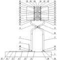
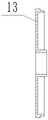
具体使用过程如下:在初始状态下,除冰机构呈合拢状态,如图1所示。当要进行除冰时,利用液压泵站驱动液压千斤顶伸长,液压千斤顶推动两根Z形导杆一起上升(两根Z形导杆的下部杆段分别沿着两根套管向上伸出),两根Z形导杆推动两个箱形保护罩、两个竖条形盖板、六个超声振子、六个节圆盘、六个除冰工具头一起上升。在上升过程中,向左拉动U形把手,U形把手带动滑块向左滑动(压簧发生压缩变形),滑块带动第一个铰座向左移动,由此一方面使得第一根套管围绕第一个铰座进行顺时针转动,另一方面使得第二根套管围绕第二个铰座进行逆时针转动,从而带动除冰机构进行张开,如图13所示(在第一根套管的带动下,第一根Z形导杆、第二个箱形保护罩、第二个竖条形盖板、第四至第六个超声振子、第四至第六个节圆盘、第四至第六个除冰工具头一起进行顺时针转动。在第二根套管的带动下,第二根Z形导杆、第一个箱形保护罩、第一个竖条形盖板、第一至第三个超声振子、第一至第三个节圆盘、第一至第三个除冰工具头一起进行逆时针转动)。在张开过程中,两根Z形导杆的交叉铰接处会向左移动,因此需要推动平板小车向左移动,以保证液压千斤顶的顶头与两根Z形导杆的交叉铰接处稳定接触。待六个除冰工具头上升至与架空输电线路上覆盖的冰层接触时,停止驱动液压千斤顶,并松开U形把手。此时,在压簧的恢复力作用下,六个除冰工具头对架空输电线路上覆盖的冰层形成稳定夹持。然后,启动外部超声波发生器和外部电源。外部超声波发生器将交流电转换为超声频交变电流信号,并将超声频交变电流信号传输至六个超声振子的换能器。六个超声振子的换能器将超声频交变电流信号转换为超声频机械振动。超声频机械振动经六个超声振子的变幅杆进行放大后,带动六个除冰工具头进行超声频机械振动,六个除冰工具头由此带动架空输电线路上覆盖的冰层进行超声频机械振动,从而实现超声振动除冰。同时,外部电源向六个矩形电加热板通电并使之发热,六个除冰工具头由此对架空输电线路上覆盖的冰层进行加热并使之融化,从而实现电加热除冰。在超声振动除冰和电加热除冰过程中,冰层的融化区在超声频机械振动的作用下发生超声空化,由此实现超声空化除冰。The specific use process is as follows: In the initial state, the deicing mechanism is in a closed state, as shown in Figure 1. When de-icing is to be performed, the hydraulic pump station is used to drive the hydraulic jack to extend, and the hydraulic jack pushes the two Z-shaped guide rods to rise together (the lower rod sections of the two Z-shaped guide rods extend upward along the two casings respectively) , Two Z-shaped guide rods push two box-shaped protective covers, two vertical strip-shaped cover plates, six ultrasonic vibrators, six pitch discs, and six deicing tool heads to rise together. During the ascending process, pull the U-shaped handle to the left, the U-shaped handle drives the slider to slide to the left (the compression spring is compressed and deformed), and the slider drives the first hinge seat to move to the left, which on the one hand makes the first sleeve The tube rotates clockwise around the first hinge seat, on the other hand, the second sleeve rotates counterclockwise around the second hinge seat, thereby driving the de-icing mechanism to open, as shown in Figure 13 (in the first Driven by the sleeve, the first Z-shaped guide rod, the second box-shaped protective cover, the second vertical bar-shaped cover, the fourth to sixth ultrasonic vibrators, and the fourth to sixth pitch discs , the fourth to sixth deicing tool heads rotate clockwise together. Driven by the second sleeve, the second Z-shaped guide rod, the first box-shaped protective cover, and the first vertical bar-shaped cover plate, the first to third ultrasonic vibrators, the first to third pitch discs, and the first to third deicing tool heads rotate counterclockwise together). During the opening process, the cross joint of the two Z-shaped guide rods will move to the left, so it is necessary to push the flatbed trolley to move to the left to ensure stable contact between the head of the hydraulic jack and the cross joint of the two Z-shaped guide rods. When the six deicing tool heads rise to contact with the ice covering the overhead transmission line, stop driving the hydraulic jack and release the U-shaped handle. At this time, under the action of the restoring force of the compression spring, the six deicing tool heads form a stable grip on the ice layer covered on the overhead transmission line. Then, start the external sonotrode and external power supply. The external ultrasonic generator converts the alternating current into an ultrasonic frequency alternating current signal, and transmits the ultrasonic frequency alternating current signal to the transducer of the six ultrasonic vibrators. The transducers of six ultrasonic vibrators convert ultrasonic alternating current signals into ultrasonic mechanical vibrations. After the ultrasonic mechanical vibration is amplified by the horn of the six ultrasonic vibrators, it drives the six deicing tool heads to perform ultrasonic mechanical vibration, and the six deicing tool heads drive the ice layer covered on the overhead transmission line to carry out ultrasonic vibration. Mechanical vibration, so as to achieve ultrasonic vibration de-icing. At the same time, the external power supply energizes the six rectangular electric heating plates to generate heat, and the six deicing tool heads heat and melt the ice layer covered on the overhead transmission line, thereby realizing electric heating and deicing. In the process of ultrasonic vibration deicing and electric heating deicing, ultrasonic cavitation occurs in the melting zone of the ice layer under the action of ultrasonic mechanical vibration, thereby realizing ultrasonic cavitation deicing.
基于上述过程,与现有架空输电线路除冰方法相比,本发明所述的一种用于架空输电线路的复合式除冰装置将超声振动除冰、电加热除冰、超声空化除冰相结合,实现了复合式除冰,由此具备了如下优点:其一,与红外线除冰法、电加热除冰法、高速热流除冰法相比,本发明能耗更低,且有效避免了二次结冰的风险。其二,与化学物质除冰法相比,本发明在除冰过程中不会留下死角,由此使得除冰更彻底。其三,与超声导波除冰法相比,本发明不仅适用于清除较薄的冰层,而且适用于清除较厚的冰层,由此使得适用范围更广。Based on the above process, compared with the existing method for deicing overhead transmission lines, the composite deicing device for overhead transmission lines described in the present invention combines ultrasonic vibration deicing, electric heating deicing, and ultrasonic cavitation deicing for deicing. Combined, the composite deicing is realized, which has the following advantages: First, compared with the infrared deicing method, the electric heating deicing method, and the high-speed heat flow deicing method, the present invention has lower energy consumption and effectively avoids the Risk of secondary icing. Second, compared with the chemical deicing method, the present invention does not leave dead corners in the deicing process, thereby making the deicing more thorough. Third, compared with the ultrasonic guided wave deicing method, the present invention is not only suitable for removing thinner ice layers, but also for removing thicker ice layers, thereby making the scope of application wider.
本发明结构合理、设计巧妙,有效解决了现有架空输电线路除冰方法能耗较高、存在二次结冰风险、除冰不彻底、适用范围受限的问题,其除冰效率高、操作简单省力,适用于架空输电线路除冰。The invention has reasonable structure and ingenious design, effectively solves the problems of high energy consumption, secondary icing risk, incomplete deicing and limited application scope of the existing overhead transmission line deicing method, and has high deicing efficiency and operation. Simple and labor-saving, suitable for deicing overhead transmission lines.
附图说明Description of drawings
图1是本发明的结构示意图。Figure 1 is a schematic structural diagram of the present invention.
图2是图1的左视图。FIG. 2 is a left side view of FIG. 1 .
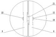
图3是图2中A处的局部放大图。FIG. 3 is a partial enlarged view of A in FIG. 2 .
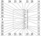
图4是本发明中除冰机构的部分结构示意图一。FIG. 4 is a partial structural schematic diagram 1 of the deicing mechanism in the present invention.
图5是图4的部分结构示意图。FIG. 5 is a partial structural schematic diagram of FIG. 4 .
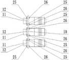
图6是本发明中除冰机构的部分结构示意图二。FIG. 6 is a second partial structural schematic diagram of the deicing mechanism in the present invention.
图7是图6的部分结构示意图。FIG. 7 is a partial structural schematic diagram of FIG. 6 .
图8是本发明中竖条形盖板的结构示意图。FIG. 8 is a schematic structural diagram of a vertical strip cover plate in the present invention.
图9是本发明中除冰工具头的剖面结构示意图。FIG. 9 is a schematic cross-sectional structure diagram of the deicing tool head in the present invention.
图10是本发明中矩形杯状壳体的剖面结构示意图。FIG. 10 is a schematic cross-sectional structure diagram of a rectangular cup-shaped casing in the present invention.
图11是本发明中矩形杯状盖体的剖面结构示意图。FIG. 11 is a schematic cross-sectional structure diagram of a rectangular cup-shaped cover body in the present invention.
图12是本发明中矩形电加热板的剖面结构示意图。12 is a schematic cross-sectional structure diagram of a rectangular electric heating plate in the present invention.
图13是本发明的使用状态参考图。FIG. 13 is a reference diagram of the use state of the present invention.
图14是图13的俯视图。FIG. 14 is a plan view of FIG. 13 .
图15是图14的部分结构示意图。FIG. 15 is a partial structural schematic diagram of FIG. 14 .
图16是图15的A-A剖视图。FIG. 16 is a cross-sectional view taken along line A-A of FIG. 15 .
图中:1-横条形座板,2-滑块,3-压簧,4-横条形挡板,5-U形把手,6-铰座,7-套管,8-Z形导杆,9-箱形保护罩,10-竖条形盖板,11-超声振子,12-节圆盘,13-矩形杯状壳体,14-矩形杯状盖体,15-矩形电加热板,16-沉头螺钉,17-螺钉A,18-螺钉B,19-铰接耳座,20-双头铆钉,21-轴套,22-垫片,23-螺栓A,24-螺母A,25-螺栓B,26-螺母B。In the picture: 1- horizontal bar-shaped seat plate, 2- slide block, 3- compression spring, 4- horizontal bar-shaped baffle, 5- U-shaped handle, 6- hinge seat, 7- sleeve, 8-Z-shaped guide Rod, 9-box-shaped protective cover, 10-vertical bar-shaped cover plate, 11-ultrasonic vibrator, 12-section disc, 13-rectangular cup-shaped shell, 14-rectangular cup-shaped cover, 15-rectangular electric heating plate , 16- Countersunk Head Screw, 17- Screw A, 18- Screw B, 19- Hinged Ear Seat, 20- Double Head Rivet, 21- Bush, 22- Washer, 23- Bolt A, 24- Nut A, 25 - Bolt B, 26 - Nut B.
具体实施方式Detailed ways
一种用于架空输电线路的复合式除冰装置,包括操作机构和除冰机构;A composite deicing device for overhead transmission lines, comprising an operating mechanism and a deicing mechanism;
所述操作机构包括横条形座板1、滑块2、压簧3、两个横条形挡板4、U形把手5、两个铰座6、两根套管7;The operating mechanism includes a horizontal bar-shaped
横条形座板1的上表面开设有两端封闭的横条形凹槽;滑块2滑动装配于横条形凹槽内,且滑块2的上表面与横条形座板1的上表面齐平;压簧3位于横条形凹槽内,且压簧3的两端分别与横条形凹槽的左槽壁和滑块2的左表面接触;第一个横条形挡板4搭接固定于横条形凹槽的槽口左边沿前端、槽口前边沿、槽口右边沿前端;第二个横条形挡板4搭接固定于横条形凹槽的槽口左边沿后端、槽口后边沿、槽口右边沿后端;U形把手5的开口朝下,且U形把手5的顶边呈纵向设置;U形把手5的两个侧边均垂直固定于滑块2的上表面左部;第一个铰座6固定于滑块2的上表面中部;第二个铰座6固定于横条形座板1的上表面,且第二个铰座6位于横条形凹槽的右方;两根套管7的下端分别铰接于两个铰座6上;The upper surface of the horizontal bar-shaped seat plate 1 is provided with a horizontal bar-shaped groove with closed ends; The surface is flush; the compression spring 3 is located in the horizontal bar-shaped groove, and both ends of the compression spring 3 are in contact with the left groove wall of the horizontal bar-shaped groove and the left surface of the slider 2; the first horizontal bar-shaped baffle 4 lapped and fixed on the front end of the left edge of the notch, the front edge of the notch, and the front end of the right edge of the notch; the second horizontal strip baffle 4 is lapped and fixed on the left side of the notch of the horizontal bar groove Along the rear end, the rear edge of the notch, and the rear end of the right edge of the notch; the opening of the U-shaped handle 5 faces downward, and the top edge of the U-shaped handle 5 is arranged longitudinally; both sides of the U-shaped handle 5 are vertically fixed to The left part of the upper surface of the slider 2; the first hinge seat 6 is fixed on the middle part of the upper surface of the slider 2; the second hinge seat 6 is fixed on the upper surface of the horizontal strip seat plate 1, and the second hinge seat 6 Located on the right side of the horizontal strip groove; the lower ends of the two sleeves 7 are hinged on the two hinge seats 6 respectively;
所述除冰机构包括两根Z形导杆8、两个箱形保护罩9、两个竖条形盖板10、六个超声振子11、六个节圆盘12、六个除冰工具头;The deicing mechanism includes two Z-shaped
每根Z形导杆8均包括下部杆段、中间杆段、上部杆段;两根Z形导杆8的下部杆段分别滑动插设于两根套管7内;两根Z形导杆8的中间杆段交叉铰接;两个箱形保护罩9分别支撑固定于两根Z形导杆8的上部杆段上端面;第一个箱形保护罩9的右端设有敞口;第二个箱形保护罩9的左端设有敞口;第一个竖条形盖板10封盖于第一个箱形保护罩9的右端敞口上;第二个竖条形盖板10封盖于第二个箱形保护罩9的左端敞口上;每个竖条形盖板10的表面均贯通开设有三个沿竖向等距排列的支撑孔;第一至第三个超声振子11的换能器均位于第一个箱形保护罩9内,且第一至第三个超声振子11的变幅杆一一对应地固定贯穿第一个竖条形盖板10上的三个支撑孔;第四至第六个超声振子11的换能器均位于第二个箱形保护罩9内,且第四至第六个超声振子11的变幅杆一一对应地固定贯穿第二个竖条形盖板10上的三个支撑孔;第一至第三个超声振子11的变幅杆右端面中央、第四至第六个超声振子11的变幅杆左端面中央各开设有一个盲螺孔;第一至第三个节圆盘12一一对应地一体设置于第一至第三个超声振子11的变幅杆节圆处,且第一至第三个节圆盘12均贴附固定于第一个竖条形盖板10的右表面;第四至第六个节圆盘12一一对应地一体设置于第四至第六个超声振子11的变幅杆节圆处,且第四至第六个节圆盘12均贴附固定于第二个竖条形盖板10的左表面;六个除冰工具头一一对应地安装于第一至第三个超声振子11的变幅杆右端、第四至第六个超声振子11的变幅杆左端;每个除冰工具头均包括矩形杯状壳体13、矩形杯状盖体14、矩形电加热板15、沉头螺钉16;矩形杯状壳体13的底壁中央贯通开设有中心孔A;矩形杯状壳体13的内底壁延伸设置有圆环形凸台,且圆环形凸台的内侧壁与中心孔A的孔壁衔接为一体;矩形杯状盖体14的底壁中央贯通开设有外粗内细的台阶孔,且台阶孔的细孔孔径与中心孔A的孔径一致;矩形杯状盖体14与矩形杯状壳体13对接构成安装腔体,且矩形杯状盖体14的底壁搭接固定于圆环形凸台的端面;矩形电加热板15的表面中央贯通开设有中心孔B;矩形电加热板15嵌设于安装腔体内,且中心孔B的孔壁与圆环形凸台的外侧壁配合;沉头螺钉16依次穿过台阶孔、圆环形凸台、中心孔A旋拧于对应超声振子11上的盲螺孔内。Each Z-shaped guide rod 8 includes a lower rod section, a middle rod section, and an upper rod section; the lower rod sections of the two Z-shaped guide rods 8 are slidably inserted into the two sleeves 7 respectively; the two Z-shaped guide rods The middle rod section of the The left end of each box-shaped protective cover 9 is provided with an opening; the first vertical strip-shaped cover 10 is covered on the opening of the right end of the first box-shaped protective cover 9; the second vertical strip-shaped cover 10 is covered on The left end of the second box-shaped protective cover 9 is open; the surface of each vertical strip-shaped cover plate 10 is provided with three supporting holes arranged at equal distances vertically; the energy conversion of the first to third ultrasonic vibrators 11 The horns are all located in the first box-shaped protective cover 9, and the horns of the first to third ultrasonic vibrators 11 are fixed in one-to-one correspondence through the three support holes on the first vertical strip-shaped cover plate 10; The transducers of the fourth to sixth ultrasonic vibrators 11 are all located in the second box-shaped protective cover 9 , and the horns of the fourth to sixth ultrasonic vibrators 11 are fixed one-to-one through the second vertical bar. The three support holes on the cover plate 10; the center of the right end face of the horn of the first to third ultrasonic vibrators 11 and the center of the left end face of the horn of the fourth to sixth ultrasonic vibrators 11 are respectively provided with a blind screw hole ; The first to third pitch discs 12 are integrally arranged at the pitch circles of the horns of the first to third ultrasonic oscillators 11 in one-to-one correspondence, and the first to third pitch discs 12 are all attached and fixed On the right surface of the first vertical strip cover 10; the fourth to sixth pitch discs 12 are integrally arranged at the pitch circles of the fourth to sixth ultrasonic vibrators 11 in one-to-one correspondence, and the first The fourth to sixth pitch discs 12 are all attached and fixed to the left surface of the second vertical strip cover 10 ; The right end of the horn and the left end of the horn of the fourth to sixth ultrasonic oscillators 11; each deicing tool head includes a rectangular cup-shaped casing 13, a rectangular cup-shaped cover 14, a rectangular electric heating plate 15, and a countersunk head screw 16; the center of the bottom wall of the rectangular cup-shaped shell 13 is provided with a central hole A; the inner bottom wall of the rectangular cup-shaped shell 13 is extended with a circular boss, and the inner side wall of the circular boss and the central hole The hole walls of A are connected as a whole; the center of the bottom wall of the rectangular cup-shaped cover 14 is provided with a stepped hole with an outer thickness and a fine inner diameter, and the aperture of the stepped hole is consistent with the aperture of the central hole A; the rectangular cup-shaped cover 14 The installation cavity is formed by docking with the rectangular cup-shaped shell 13, and the bottom wall of the rectangular cup-shaped cover 14 is overlapped and fixed on the end face of the annular boss; the center of the surface of the rectangular electric heating plate 15 is provided with a central hole B; The rectangular electric heating plate 15 is embedded in the installation cavity, and the hole wall of the central hole B is matched with the outer side wall of the annular boss; Screw it into the blind screw hole on the corresponding ultrasonic vibrator 11 .
还包括两组螺钉A17;第一个横条形挡板4通过第一组螺钉A17搭接固定于横条形凹槽的槽口左边沿前端、槽口前边沿、槽口右边沿前端;第二个横条形挡板4通过第二组螺钉A17搭接固定于横条形凹槽的槽口左边沿后端、槽口后边沿、槽口右边沿后端。It also includes two sets of screws A17; the first
还包括两组螺钉B18;第一个铰座6通过第一组螺钉B18固定于滑块2的上表面中部;第二个铰座6通过第二组螺钉B18固定于横条形座板1的上表面。It also includes two sets of screws B18; the
两根套管7的下端均设有端壁,且两根套管7的下外端壁各延伸设置有一个铰接耳座19;两根套管7的下端分别通过两个铰接耳座19铰接于两个铰座6上。The lower ends of the two
还包括双头铆钉20、轴套21、两个垫片22;两根Z形导杆8的中间杆段通过双头铆钉20交叉铰接;轴套21套设于双头铆钉20的侧面,且轴套21位于两根Z形导杆8的中间杆段之间;两个垫片22均套设于双头铆钉20的侧面;第一个垫片22位于双头铆钉20的第一个头部和第一根Z形导杆8的中间杆段之间;第二个垫片22位于双头铆钉20的第二个头部和第二根Z形导杆8的中间杆段之间。It also includes a double-ended
还包括两组螺栓A23和两组螺母A24;第一个箱形保护罩9的右端敞口边沿、第二个箱形保护罩9的左端敞口边沿均为外折边;第一个竖条形盖板10通过第一组螺栓A23和第一组螺母A24封盖于第一个箱形保护罩9的右端敞口上;第二个竖条形盖板10通过第二组螺栓A23和第二组螺母A24封盖于第二个箱形保护罩9的左端敞口上。It also includes two sets of bolts A23 and two sets of nuts A24; the open edge of the right end of the first box-shaped
还包括六组螺栓B25和六组螺母B26;第一至第三个节圆盘12通过第一至第三组螺栓B25和第一至第三组螺母B26贴附固定于第一个竖条形盖板10的右表面;第四至第六个节圆盘12通过第四至第六组螺栓B25和第四至第六组螺母B26贴附固定于第二个竖条形盖板10的左表面。It also includes six sets of bolts B25 and six sets of nuts B26; the first to
U形把手5的顶边侧面套设有绝缘套。The top edge and side surface of the
虽然以上描述了本发明的具体实施方式,但是本领域的技术人员应当理解,这些仅是举例说明,本发明的保护范围是由所附权利要求书限定的。本领域的技术人员在不背离本发明的原理和实质的前提下,可以对这些实施方式作出多种变更或修改,但这些变更和修改均落入本发明的保护范围。Although specific embodiments of the present invention have been described above, those skilled in the art will understand that these are merely illustrative and the scope of the present invention is defined by the appended claims. Those skilled in the art can make various changes or modifications to these embodiments without departing from the principle and essence of the present invention, but these changes and modifications all fall within the protection scope of the present invention.
Claims (8)
Priority Applications (1)
| Application Number | Priority Date | Filing Date | Title |
|---|---|---|---|
| CN202210169866.XACN114498519B (en) | 2022-02-24 | 2022-02-24 | Composite deicing device for overhead transmission line |
Applications Claiming Priority (1)
| Application Number | Priority Date | Filing Date | Title |
|---|---|---|---|
| CN202210169866.XACN114498519B (en) | 2022-02-24 | 2022-02-24 | Composite deicing device for overhead transmission line |
Publications (2)
| Publication Number | Publication Date |
|---|---|
| CN114498519Atrue CN114498519A (en) | 2022-05-13 |
| CN114498519B CN114498519B (en) | 2023-07-04 |
Family
ID=81483413
Family Applications (1)
| Application Number | Title | Priority Date | Filing Date |
|---|---|---|---|
| CN202210169866.XAExpired - Fee RelatedCN114498519B (en) | 2022-02-24 | 2022-02-24 | Composite deicing device for overhead transmission line |
Country Status (1)
| Country | Link |
|---|---|
| CN (1) | CN114498519B (en) |
Citations (11)
| Publication number | Priority date | Publication date | Assignee | Title |
|---|---|---|---|---|
| US20100243633A1 (en)* | 2009-03-24 | 2010-09-30 | Tung Huynh | Power Line De-Icing Apparatus |
| CN102780192A (en)* | 2011-12-19 | 2012-11-14 | 杭州电子科技大学 | Ultrasonic wire deicing device and method thereof |
| CA2852568A1 (en)* | 2013-09-05 | 2015-03-05 | Young Ki Kim | Device for removing ice and snow from power transmission line |
| CN106025982A (en)* | 2016-06-23 | 2016-10-12 | 陈晨 | Electric power transmission line deicing industrial robot |
| WO2016192570A1 (en)* | 2015-06-01 | 2016-12-08 | 丁孟春 | Adjustment mechanism for de-icing unit, de-icing unit and de-icing device |
| CN206481022U (en)* | 2017-02-28 | 2017-09-08 | 东北石油大学 | A kind of deicer of high voltage transmission line |
| CN107528281A (en)* | 2017-09-30 | 2017-12-29 | 国家电网公司 | A kind of high-voltage testing room conducting wire deicing system |
| CN111987679A (en)* | 2020-09-03 | 2020-11-24 | 广东电网有限责任公司东莞供电局 | A detection and processing device for ice coating of transmission lines |
| CN112260201A (en)* | 2020-11-01 | 2021-01-22 | 杨友明 | Machinery field is with novel transmission line deicing equipment |
| KR102222707B1 (en)* | 2020-08-24 | 2021-03-04 | (주)사성기술단 | Fixation device for preventing derailment of ultra-high pressure machined transmission tracks |
| CN214100776U (en)* | 2021-01-10 | 2021-08-31 | 靳春艳 | Icing clearing device suitable for overhead transmission line |
- 2022
- 2022-02-24CNCN202210169866.XApatent/CN114498519B/ennot_activeExpired - Fee Related
Patent Citations (11)
| Publication number | Priority date | Publication date | Assignee | Title |
|---|---|---|---|---|
| US20100243633A1 (en)* | 2009-03-24 | 2010-09-30 | Tung Huynh | Power Line De-Icing Apparatus |
| CN102780192A (en)* | 2011-12-19 | 2012-11-14 | 杭州电子科技大学 | Ultrasonic wire deicing device and method thereof |
| CA2852568A1 (en)* | 2013-09-05 | 2015-03-05 | Young Ki Kim | Device for removing ice and snow from power transmission line |
| WO2016192570A1 (en)* | 2015-06-01 | 2016-12-08 | 丁孟春 | Adjustment mechanism for de-icing unit, de-icing unit and de-icing device |
| CN106025982A (en)* | 2016-06-23 | 2016-10-12 | 陈晨 | Electric power transmission line deicing industrial robot |
| CN206481022U (en)* | 2017-02-28 | 2017-09-08 | 东北石油大学 | A kind of deicer of high voltage transmission line |
| CN107528281A (en)* | 2017-09-30 | 2017-12-29 | 国家电网公司 | A kind of high-voltage testing room conducting wire deicing system |
| KR102222707B1 (en)* | 2020-08-24 | 2021-03-04 | (주)사성기술단 | Fixation device for preventing derailment of ultra-high pressure machined transmission tracks |
| CN111987679A (en)* | 2020-09-03 | 2020-11-24 | 广东电网有限责任公司东莞供电局 | A detection and processing device for ice coating of transmission lines |
| CN112260201A (en)* | 2020-11-01 | 2021-01-22 | 杨友明 | Machinery field is with novel transmission line deicing equipment |
| CN214100776U (en)* | 2021-01-10 | 2021-08-31 | 靳春艳 | Icing clearing device suitable for overhead transmission line |
Non-Patent Citations (1)
| Title |
|---|
| 张天乐;: "一种架空电缆除冰机设备研制", 科技创新导报, no. 23* |
Also Published As
| Publication number | Publication date |
|---|---|
| CN114498519B (en) | 2023-07-04 |
Similar Documents
| Publication | Publication Date | Title |
|---|---|---|
| CN212323847U (en) | Energy-saving permanent magnet synchronous motor | |
| CN206481022U (en) | A kind of deicer of high voltage transmission line | |
| CN114498519A (en) | Composite deicing device for overhead transmission line | |
| CN207265168U (en) | A kind of soft-package battery constant pressure formation device | |
| CN114178580A (en) | Double-station reaming tool for automobile chassis bushing | |
| CN208962506U (en) | A kind of ultrasonic plastic welder | |
| CN216399988U (en) | Use green building technology's hollow brick forming device | |
| CN216576028U (en) | Aluminum alloy battery case welding heating device | |
| CN214698385U (en) | Convenient centrifugal fan who dismantles | |
| CN212603472U (en) | Wear-resisting type ultrasonic welding mould | |
| CN211358934U (en) | A breaker for gaseous raw materials for production | |
| CN213410857U (en) | Air cock welding machine for air spacer | |
| CN221312854U (en) | A multi-head ultrasonic welding equipment | |
| CN222338322U (en) | A positioning device for a battery tab gluing machine | |
| CN218976485U (en) | Traction motor outlet device for railway vehicle | |
| CN221993346U (en) | A device for detecting foreign objects on tracks based on machine vision | |
| CN222831171U (en) | A razor head assembly tool | |
| CN214819264U (en) | Novel cutting device for plywood | |
| CN218283537U (en) | Aluminum core honeycomb panel aluminum core processing device | |
| CN219254279U (en) | Square shell cutting device of lithium battery | |
| CN216609129U (en) | Automatic cutting equipment of high-efficient anti-skidding automobile sealing strip | |
| CN117712546B (en) | Novel household energy storage device | |
| CN219181285U (en) | Motor convenient to disassemble and maintain | |
| CN222635443U (en) | An ultrasonic transducer device for TOFD inspection of special thick wall workpieces | |
| CN218349272U (en) | Combined laminated cooling and heat dissipation box |
Legal Events
| Date | Code | Title | Description |
|---|---|---|---|
| PB01 | Publication | ||
| PB01 | Publication | ||
| SE01 | Entry into force of request for substantive examination | ||
| SE01 | Entry into force of request for substantive examination | ||
| GR01 | Patent grant | ||
| GR01 | Patent grant | ||
| CF01 | Termination of patent right due to non-payment of annual fee | ||
| CF01 | Termination of patent right due to non-payment of annual fee | Granted publication date:20230704 |