CN114498041A - A transmission line assembly, an antenna assembly and a mobile terminal - Google Patents
A transmission line assembly, an antenna assembly and a mobile terminalDownload PDFInfo
- Publication number
- CN114498041A CN114498041ACN202110943245.8ACN202110943245ACN114498041ACN 114498041 ACN114498041 ACN 114498041ACN 202110943245 ACN202110943245 ACN 202110943245ACN 114498041 ACN114498041 ACN 114498041A
- Authority
- CN
- China
- Prior art keywords
- transmission line
- filter
- antenna
- outer conductor
- clutter
- Prior art date
- Legal status (The legal status is an assumption and is not a legal conclusion. Google has not performed a legal analysis and makes no representation as to the accuracy of the status listed.)
- Granted
Links
Images


Classifications
- H—ELECTRICITY
- H01—ELECTRIC ELEMENTS
- H01Q—ANTENNAS, i.e. RADIO AERIALS
- H01Q13/00—Waveguide horns or mouths; Slot antennas; Leaky-waveguide antennas; Equivalent structures causing radiation along the transmission path of a guided wave
- H01Q13/08—Radiating ends of two-conductor microwave transmission lines, e.g. of coaxial lines, of microstrip lines
- H—ELECTRICITY
- H01—ELECTRIC ELEMENTS
- H01Q—ANTENNAS, i.e. RADIO AERIALS
- H01Q1/00—Details of, or arrangements associated with, antennas
- H01Q1/12—Supports; Mounting means
- H01Q1/22—Supports; Mounting means by structural association with other equipment or articles
- H—ELECTRICITY
- H01—ELECTRIC ELEMENTS
- H01Q—ANTENNAS, i.e. RADIO AERIALS
- H01Q1/00—Details of, or arrangements associated with, antennas
- H01Q1/48—Earthing means; Earth screens; Counterpoises
- H—ELECTRICITY
- H01—ELECTRIC ELEMENTS
- H01Q—ANTENNAS, i.e. RADIO AERIALS
- H01Q5/00—Arrangements for simultaneous operation of antennas on two or more different wavebands, e.g. dual-band or multi-band arrangements
- H01Q5/20—Arrangements for simultaneous operation of antennas on two or more different wavebands, e.g. dual-band or multi-band arrangements characterised by the operating wavebands
Landscapes
- Details Of Aerials (AREA)
- Control Of Motors That Do Not Use Commutators (AREA)
Abstract
Description
Translated fromChinese本申请要求在2020年10月27日提交中国专利局、申请号为202022428861.3、申请名称为“一种传输线组件、天线组件和移动终端”的中国专利申请的优先权,其全部内容通过引用结合在本申请中。This application claims the priority of the Chinese patent application with the application number 202022428861.3 and the application title "A Transmission Line Assembly, Antenna Assembly and Mobile Terminal" filed with the China Patent Office on October 27, 2020, the entire contents of which are incorporated by reference in in this application.
技术领域technical field
本申请涉及通信技术领域,尤其涉及一种传输线组件、天线组件和移动终端。The present application relates to the field of communication technologies, and in particular, to a transmission line assembly, an antenna assembly and a mobile terminal.
背景技术Background technique
传输线被广泛应用在手机、平板电脑等移动终端设备中。作为信号的传输媒介,主要是实现电路板与电路板之间射频信号的传递,或者,电路板与天线之间射频信号的传递。Transmission lines are widely used in mobile terminal devices such as mobile phones and tablet computers. As a signal transmission medium, it mainly realizes the transmission of radio frequency signals between circuit boards and circuit boards, or the transmission of radio frequency signals between circuit boards and antennas.
在实际应用时,由于传输线的长度和射频工作波长接近,如果传输线设置在靠近天线的位置,在使用过程中,很容易在天线带内产生一连串杂波,这些杂波不仅会降低天线的辐射效率和信号传输质量,还会影响移动终端设备的品质一致性,因此,如何降低或避免传输线中杂波对天线的影响成为了亟待解决的技术问题。In practical applications, since the length of the transmission line is close to the working wavelength of the radio frequency, if the transmission line is set close to the antenna, it is easy to generate a series of clutter in the antenna band during use. These clutter will not only reduce the radiation efficiency of the antenna and signal transmission quality, and will also affect the quality consistency of the mobile terminal equipment. Therefore, how to reduce or avoid the influence of clutter in the transmission line on the antenna has become an urgent technical problem to be solved.
发明内容SUMMARY OF THE INVENTION
本申请提供了一种有助于改善杂波问题的传输线组件、天线组件和移动终端。The present application provides a transmission line assembly, an antenna assembly and a mobile terminal that help to improve the clutter problem.
一方面,本申请提供了一种传输线组件,包括传输线和第一滤波器。传输线用于传输射频信号,且传输线具有第一端和第二端。其中传输线包括内导体和外导体,第一滤波器与传输线的外导体的一端连接,且外导体的第一端通过滤波器接地。In one aspect, the present application provides a transmission line assembly including a transmission line and a first filter. The transmission line is used for transmitting radio frequency signals, and the transmission line has a first end and a second end. The transmission line includes an inner conductor and an outer conductor, the first filter is connected to one end of the outer conductor of the transmission line, and the first end of the outer conductor is grounded through the filter.
在具体实施时,传输线可以是同轴传输线、微带传输线、液晶聚合物传输线、改性聚酰亚胺传输线等。In a specific implementation, the transmission line may be a coaxial transmission line, a microstrip transmission line, a liquid crystal polymer transmission line, a modified polyimide transmission line, or the like.
以同轴传输线和微带传输线为例。Take coaxial transmission lines and microstrip transmission lines as examples.
微带传输线是由支在介质基片上的单一导体构成的微波传输线,基片的另一面制作有接地金属平板。微带传输线适合制作微波集成电路的平面结构传输线。微带传输线具有体积小、重量轻、使用频带宽、可靠性稿和制造成本低等优点。其中,微带传输线可以设置在印制电路板(Printed Circuit Board,PCB)上,也可以设置在柔性电路板(FlexiblePrinted Circuit,FPC)上。在此不作限制。The microstrip transmission line is a microwave transmission line composed of a single conductor supported on a dielectric substrate, and the other side of the substrate is made with a grounded metal plate. The microstrip transmission line is suitable for making the planar structure transmission line of the microwave integrated circuit. Microstrip transmission lines have the advantages of small size, light weight, wide bandwidth, low reliability and low manufacturing cost. The microstrip transmission line may be arranged on a printed circuit board (Printed Circuit Board, PCB), or may be arranged on a flexible printed circuit (Flexible Printed Circuit, FPC). There is no restriction here.
同轴传输线是一种屏蔽且非色散的结构,而且同轴传输线中导波的主模是TEM波,但同时也可以传输TE模和TM模,其截止频率为零,对应截止波长趋向于无穷大。同轴传输线是由同轴的内导体、外导体以及中间的电介质构成的双导体传输线,同轴传输线的外导体接地,电磁场被限定在内导体和外导体之间。The coaxial transmission line is a shielded and non-dispersive structure, and the main mode of the guided wave in the coaxial transmission line is the TEM wave, but it can also transmit the TE mode and the TM mode. The cutoff frequency is zero, and the corresponding cutoff wavelength tends to infinity. . The coaxial transmission line is a two-conductor transmission line composed of a coaxial inner conductor, an outer conductor and an intermediate dielectric. The outer conductor of the coaxial transmission line is grounded, and the electromagnetic field is confined between the inner conductor and the outer conductor.
另外,在具体实施时,滤波器的类型、数量以及滤波器与传输线外导体之间的连接关系也可以是多样的。In addition, during specific implementation, the types and numbers of filters and the connection relationship between the filters and the outer conductors of the transmission line can also be varied.
例如,传输线的外导体的第一端可以通过第一带阻滤波器进行接地,传输线的外导体的第二端可以通过第二带阻滤波器进行接地。For example, the first end of the outer conductor of the transmission line may be grounded through the first band-stop filter, and the second end of the outer conductor of the transmission line may be grounded through the second band-stop filter.
或者传输线的外导体的第一端直接接地,传输线的外导体的第二端可以通过带通滤波器进行接地。其中,带通滤波器可以是高通滤波器。即滤波器中包含电容,传输线外导体的第二端通过电容接地。或者,带通滤波器也可以是低通滤波器。即滤波器中包含电感,传输线外导体的第二端通过电感接地。Alternatively, the first end of the outer conductor of the transmission line is directly grounded, and the second end of the outer conductor of the transmission line may be grounded through a band-pass filter. Wherein, the band-pass filter may be a high-pass filter. That is, the filter contains a capacitor, and the second end of the outer conductor of the transmission line is grounded through the capacitor. Alternatively, the band-pass filter may also be a low-pass filter. That is, the filter contains an inductance, and the second end of the outer conductor of the transmission line is grounded through the inductance.
或者,传输线的外导体的第一端通过第一带通滤波器接地,传输线的外导体的第二端可以通过第二带通滤波器接地。其中,第一带通滤波器可以是高通滤波器、第二带通滤波器可以是高通滤波器。即第一带通滤波器中包含电容,传输线外导体的第一端通过电容接地。第二带通滤波器中包含电容,传输线外导体的第二端通过电容接地。Alternatively, the first end of the outer conductor of the transmission line may be grounded through the first bandpass filter, and the second end of the outer conductor of the transmission line may be grounded through the second bandpass filter. Wherein, the first band-pass filter may be a high-pass filter, and the second band-pass filter may be a high-pass filter. That is, the first bandpass filter includes a capacitor, and the first end of the outer conductor of the transmission line is grounded through the capacitor. The second band-pass filter includes a capacitor, and the second end of the outer conductor of the transmission line is grounded through the capacitor.
其中,第一带通滤波器可以是低通滤波器、第二带通滤波器可以是低通滤波器。即第一带通滤波器中包含电感,传输线外导体的第一端通过电感接地。第二带通滤波器中包含电感,传输线外导体的第二端通过电感接地。Wherein, the first band-pass filter may be a low-pass filter, and the second band-pass filter may be a low-pass filter. That is, the first band-pass filter includes an inductance, and the first end of the outer conductor of the transmission line is grounded through the inductance. The second band-pass filter includes an inductance, and the second end of the outer conductor of the transmission line is grounded through the inductance.
可以理解的是,在具体应用时,第一滤波器和第二滤波器的类型可以相同也可以不同。在此不作具体限定。It can be understood that, in specific applications, the types of the first filter and the second filter may be the same or different. There is no specific limitation here.
另外,本申请实施例还提供了一种天线组件,包括天线和线缆组件。在本申请提供的天线组件中,将传输线通过滤波器接地,能够对传输线工作频段以外的杂波进行调谐,以降低或避免杂波对传输线附近的天线的效率所造成的影响。In addition, an embodiment of the present application also provides an antenna assembly, including an antenna and a cable assembly. In the antenna assembly provided by the present application, the transmission line is grounded through a filter, so that the clutter outside the operating frequency band of the transmission line can be tuned, so as to reduce or avoid the influence of the clutter on the efficiency of the antenna near the transmission line.
在具体实施时,天线的设置数量以及设置位置可以根据不同需求进行适应性选择和调整,本申请对此不作限定。During specific implementation, the number of antennas to be installed and the installation positions can be adaptively selected and adjusted according to different requirements, which is not limited in this application.
例如,天线组件可以包括第一天线、第二天线、第一传输线、第二传输线。第一传输线用于向第一天线传输射频信号,第二传输线用于向第二天线传输射频信号。For example, the antenna assembly may include a first antenna, a second antenna, a first transmission line, a second transmission line. The first transmission line is used for transmitting radio frequency signals to the first antenna, and the second transmission line is used for transmitting radio frequency signals to the second antenna.
在具体实施时,第一天线的工作频段和第二天线的工作频段可以不同。例如,第一天线可以是用于产生低频信号的天线,第二天线可以是用于产生中高频信号的天线。During specific implementation, the working frequency band of the first antenna and the working frequency band of the second antenna may be different. For example, the first antenna may be an antenna for generating low frequency signals, and the second antenna may be an antenna for generating medium and high frequency signals.
可以理解的是,在其他的实施方式中,天线组件中还可以包括更多个天线以及传输线,本申请对此不作具体限定。It can be understood that, in other embodiments, the antenna assembly may further include more antennas and transmission lines, which are not specifically limited in this application.
另外,本申请实施例还提供了一种移动终端,包括上述的天线组件。在本申请提供的移动终端中,通过设置以上的天线组件,能够保证天线的辐射效率和信号传输质量,从而可以提升移动终端设备的品质一致性和使用效果。In addition, an embodiment of the present application further provides a mobile terminal, including the above-mentioned antenna assembly. In the mobile terminal provided by the present application, by setting the above antenna components, the radiation efficiency and signal transmission quality of the antenna can be guaranteed, thereby improving the quality consistency and use effect of the mobile terminal device.
在实际应用时,移动终端可以是手机、平板电脑等。本申请对此不作限定。In practical applications, the mobile terminal may be a mobile phone, a tablet computer, or the like. This application does not limit this.
附图说明Description of drawings
图1为本申请实施例提供的一种传输线组件的连接结构示意;FIG. 1 is a schematic diagram of a connection structure of a transmission line assembly provided by an embodiment of the present application;
图2为本申请实施例提供的一种微带传输线的剖面结构示意图;2 is a schematic cross-sectional structure diagram of a microstrip transmission line provided by an embodiment of the present application;
图3为本申请实施例提供的一种同轴传输线的立体结构示意图;3 is a schematic three-dimensional structural diagram of a coaxial transmission line provided by an embodiment of the present application;
图4为本申请实施例提供的另一种传输线组件的连接结构示意图;4 is a schematic diagram of a connection structure of another transmission line assembly provided by an embodiment of the present application;
图5为本申请实施例提供的另一种传输线中杂波信号的电流分布图;5 is a current distribution diagram of a clutter signal in another transmission line provided by an embodiment of the present application;
图6为本申请实施例提供的一个数据仿真图;Fig. 6 is a data simulation diagram provided by the embodiment of the present application;
图7为本申请实施例提供的另一种传输线组件的连接结构示意;FIG. 7 is a schematic diagram of a connection structure of another transmission line assembly provided by an embodiment of the present application;
图8为本申请实施例提供的另一种传输线中杂波信号的电流分布示意图;8 is a schematic diagram of current distribution of a clutter signal in another transmission line provided by an embodiment of the present application;
图9为本申请实施例提供的一个数据仿真图;Fig. 9 is a data simulation diagram provided by the embodiment of the present application;
图10为本申请实施例提供的另一种传输线组件的连接结构示意;FIG. 10 is a schematic diagram of a connection structure of another transmission line assembly provided by an embodiment of the application;
图11为本申请实施例提供的一种传输线组件的应用场景示意图;11 is a schematic diagram of an application scenario of a transmission line assembly provided by an embodiment of the present application;
图12为本申请实施例提供的另一种传输线组件的应用场景示意图;12 is a schematic diagram of an application scenario of another transmission line assembly provided by an embodiment of the present application;
图13为本申请实施例提供的另一种传输线中杂波信号的电流分布示意图;13 is a schematic diagram of current distribution of a clutter signal in another transmission line provided by an embodiment of the application;
图14为本申请实施例提供的第三天线的1次模杂波和3次模杂波的数据仿真图;14 is a data simulation diagram of the first-order mode clutter and the third-order mode clutter of the third antenna provided by the embodiment of the present application;
图15为本申请实施例提供的第二天线的5次模杂波和7次模杂波的数据仿真图;15 is a data simulation diagram of the 5th-order mode clutter and the 7th-order mode clutter of the second antenna provided by the embodiment of the application;
图16为本申请实施例提供的另一种传输线组件的连接结构示意;FIG. 16 is a schematic diagram of a connection structure of another transmission line assembly provided by an embodiment of the application;
图17为本申请实施例提供的另一种传输线组件的连接结构示意;FIG. 17 is a schematic diagram of a connection structure of another transmission line assembly provided by an embodiment of the present application;
图18为本申请实施例提供的另一种传输线组件的连接结构示意;FIG. 18 is a schematic diagram of a connection structure of another transmission line assembly provided by an embodiment of the present application;
图19为本申请实施例提供的另一种传输线组件的连接结构示意;FIG. 19 is a schematic diagram of a connection structure of another transmission line assembly provided by an embodiment of the application;
图20为本申请实施例提供的另一种传输线组件的连接结构示意。FIG. 20 is a schematic diagram of a connection structure of another transmission line assembly provided by an embodiment of the present application.
具体实施方式Detailed ways
为了使本申请的目的、技术方案和优点更加清楚,下面将结合附图和具体实施例对本申请作进一步地详细描述。In order to make the objectives, technical solutions and advantages of the present application clearer, the present application will be further described in detail below with reference to the accompanying drawings and specific embodiments.
以下实施例中所使用的术语只是为了描述特定实施例的目的,而并非旨在作为对本申请的限制。如在本申请的说明书和所附权利要求书中所使用的那样,单数表达形式“一个”、“一种”、“上述”、“该”和“这一”旨在也包括例如“一个或多个”这种表达形式,除非其上下文中明确地有相反指示。还应当理解,在本申请以下各实施例中,“至少一个”、“一个或多个”是指一个、两个或两个以上。术语“和/或”,用于描述关联对象的关联关系,表示可以存在三种关系;例如,A和/或B,可以表示:单独存在A,同时存在A和B,单独存在B的情况,其中A、B可以是单数或者复数。字符“/”一般表示前后关联对象是一种“或”的关系。The terms used in the following embodiments are for the purpose of describing particular embodiments only, and are not intended to be limitations of the present application. As used in the specification of this application and the appended claims, the singular expressions "a," "an," "above," "the," and "the" are intended to also include, for example, "an or Multiple" is the expression unless the context clearly dictates otherwise. It should also be understood that, in the following embodiments of the present application, "at least one" and "one or more" refer to one, two or more than two. The term "and/or", used to describe the association relationship of related objects, indicates that there can be three kinds of relationships; for example, A and/or B, can indicate: A alone exists, A and B exist at the same time, and B exists alone, A and B can be singular or plural. The character "/" generally indicates that the associated objects are an "or" relationship.
在本说明书中描述的参考“一个实施例”或“一些实施例”等意味着在本申请的一个或多个实施例中包括结合该实施例描述的特定特征、结构或特点。由此,在本说明书中的不同之处出现的语句“在一个实施例中”、“在一些实施例中”、“在其他一些实施例中”、“在另外一些实施例中”等不是必然都参考相同的实施例,而是意味着“一个或多个但不是所有的实施例”,除非是以其他方式另外特别强调。术语“包括”、“包含”、“具有”及它们的变形都意味着“包括但不限于”,除非是以其他方式另外特别强调。References in this specification to "one embodiment" or "some embodiments" and the like mean that a particular feature, structure, or characteristic described in connection with the embodiment is included in one or more embodiments of the present application. Thus, appearances of the phrases "in one embodiment," "in some embodiments," "in other embodiments," "in other embodiments," etc. in various places in this specification are not necessarily All refer to the same embodiment, but mean "one or more but not all embodiments" unless specifically emphasized otherwise. The terms "including", "including", "having" and their variants mean "including but not limited to" unless specifically emphasized otherwise.
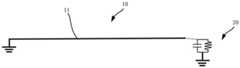
如图1所示,在本申请提供的一个实施例中,传输线组件包括传输线10和滤波器20。传输线10用于传输射频信号,且传输线10具有第一端(图中的右端)和第二端(图中的左端)。其中传输线包括内导体(图中未示出)和外导体11,滤波器20与传输线10的外导体11的右端连接,且外导体11的右端通过滤波器20接地,外导体11的左端直接接地。As shown in FIG. 1 , in one embodiment provided by the present application, the transmission line assembly includes a
在实际应用时,如图4所示,一般情况下,传输线10两端的外导体11需要进行接地处理,使得传输线10的外导体与地之间构成环结构,会产生杂波。由于杂波是由传输线10的外导体11与地之间构成的环产生的。因此,在本申请提供的传输线组件中,通过将外导体11与地之间增加滤波器20,能够保障传输线10在工作频率范围内的下地的同时,还能移动杂波位置,从而能够避免或降低杂波所产生的不良影响。In practical applications, as shown in FIG. 4 , in general, the
滤波器20作为一种选频装置,可以保障传输线10的外导体11中的部分信号频率(如所需的信号频率)可以下地,部分信号频率(如不需要的信号频率)悬空。滤波器20可以是由电容、电感、电阻组成的滤波电路,可以使传输线10中不需要的信号频率高阻悬空,使所需的信号频率下地。滤波器20按所通过信号的频段分为低通滤波器、高通滤波器和带阻滤波器。低通滤波器指的是,它允许信号中低频或直流分量通过,抑制高频分量、干扰或噪声。高通滤波器指的是,它允许信号中高频分量通过,抑制低频或直流分量。带通滤波器指的是,它允许一定频段的信号通过,抑制低于或高于该频段的信号、干扰或噪声。带阻滤波器指的是,它抑制一定频段内的信号,允许该频段以外的信号通过。As a frequency selection device, the
在具体实施时,传输线10可以是同轴传输线、微带传输线、液晶聚合物传输线、改性聚酰亚胺传输线等。In a specific implementation, the
如图2所示,微带传输线10设置在介质基片12上的单一导体13构成的微波传输线10,基片12的另一面制作有接地金属平板11。微带传输线10适合制作微波集成电路的平面结构传输线10。微带传输线10具有体积小、重量轻、使用频带宽、可靠性高和制造成本低等优点。其中,微带传输线10可以设置在印制电路板(Printed Circuit Board,PCB)上,也可以设置在柔性电路板(Flexible Printed Circuit,FPC)上。在此不作限制。As shown in FIG. 2 , the
液晶聚合物传输线10是由液晶聚合物材料(Liquid Crystal Polymer,LCP)制成的传输线10。改性聚酰亚胺传输线10是由改性聚酰亚胺材料(Polyimide,PI)制成的传输线10。The liquid crystal
需要说明的是,本申请中的传输线10可以是上述的任一种传输线10,也可以是其他类型的传输线10。It should be noted that the
为了便于理解本申请技术方案,以下实施例将以传输线10为同轴传输线10为例进行具体说明。In order to facilitate understanding of the technical solutions of the present application, the following embodiments will take the
同轴传输线10是一种屏蔽且非色散的结构,而且同轴传输线10中导波的主模是TEM模,但同时也可以传输TE模和TM模,其截止频率为零,对应截止波长趋向于无穷大。The
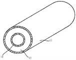
如图3所示,同轴传输线10是由同轴设置的内导体13、外导体11以及中间的电介质12构成的双导体传输线10。一般同轴传输线10外导体11接地,电磁场被限定在内导体13和外导体11之间。As shown in FIG. 3 , the
如图4所示,在实际应用时,同轴传输线10的两端可以采用扣接的方式进行外导体11信号的接地,除两端外,传输线10中外导体11的其他部分悬浮于地。As shown in FIG. 4 , in practical application, both ends of the
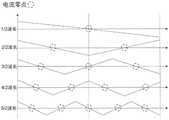
请结合参阅图4和图5,假设同轴传输线10长度为L,外导体11两端接地,外导体中间11与地隔离,在这种边界条件下,同轴传输线10的外导体11与大地构成了环模。由于传输线10的长度和射频工作波长接近,因此,如果加以激励,该环模可以产生L=n/2倍波长模式。其中,n为大于等于1的整数。奇次模(n为奇数时)中心点为电流最小点--容性区,偶次模(n为偶数时)中心点为电流最大点--感性区。在图中只列举了部分杂波模式,还有更高次的杂波模式并没有在此处一一列出。Please refer to FIG. 4 and FIG. 5 , assuming that the length of the
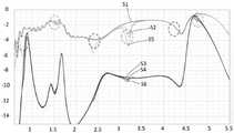
如图6所示,图中横坐标代表频率,纵坐标代表天线效率(表示为dB)。线S1表示无同轴传输线10时天线的辐射效率、线S2表示有同轴传输线10时天线的辐射效率、线S3表示有同轴传输线10时天线的系统效率、线S4表示无同轴传输线10时天线的系统效率。当同轴传输线10两端直接接地,而同轴传输线10的旁边存在一个低频天线时,从有无同轴传输线10的效率对比可发现同轴传输线10中杂波的各个模式。基模与n次倍频模式中,基模杂波落在低频带内,对天线效率有影响。在实际应用中,天线的工作频带无论是低频还是中高频,只要处于同轴传输线10区域,这些特征模都有可能会落入天线的工作频带内,因此,需要加以解决。As shown in Figure 6, the abscissa in the figure represents the frequency, and the ordinate represents the antenna efficiency (expressed in dB). Line S1 represents the radiation efficiency of the antenna without the
如图7至图9所示,在一些解除同轴传输线10杂波的方法中,可以将同轴传输线10的外导体11的两端进行接地,同时,将外导体11中部进行接地,以实现进行中心接地。从模式电流分布来看,中心接地会破坏掉中间的容性区,所有奇次模会消失。而中心接地不会破坏中间的电感区,所以偶次模会保留。As shown in FIGS. 7 to 9 , in some methods for removing clutter from the
在图9中,横坐标代表频率,纵坐标代表天线效率(表示为dB)。线S1表示无同轴传输线10时天线的辐射效率、线S2表示有两端接地的同轴传输线10时天线的辐射效率、线S5表示有两端接地和中心接地的同轴传输线10时天线的辐射效率,线S3表示有两端接地的同轴传输线10时天线的系统效率、线S4表示无同轴传输线10时天线的系统效率、线S6表示有两端接地和中心接地的同轴传输线10时天线的系统效率。当同轴传输线10两端和中间直接接地,而同轴传输线10的旁边存在一个低频天线时,从有无同轴传输线10的效率对比可发现同轴传输线10中杂波的各个模式。在对比图6和图9可以看出,当中心接地后,奇次模杂波已经消失,偶次模杂波依然存在。In FIG. 9, the abscissa represents the frequency, and the ordinate represents the antenna efficiency (expressed in dB). Line S1 shows the radiation efficiency of the antenna without the
可以理解的是,在实际应用时,在外导体11的中心位置以外的区域也可以进行接地,在此不作赘述。It can be understood that, in practical application, the area other than the center position of the
在以上的方式中,对同轴传输线10进行中心接地时,由于接地电连接比较复杂,制作成本高,容易产生电弧干扰或引入其他杂波问题,因此,存在较多的缺陷,造成良率的巨大损失。In the above method, when the center grounding of the
为此,本申请实施例通过在传输线10中引入滤波器来代替中心接地的方式,来解决杂波问题。即在解决杂波问题时,滤波器接地的方式也能达到或优于中心接地的方式所产生的效果,且滤波器接地的方式还能避免产生中心接地所带来的上述不良问题。或者,可以理解的是,通过滤波器接地的方式,能够有效解决传输线10的杂波问题,同时,便于制作,有利于降低制作成本,另外,也便于对滤波参数进行调谐。To this end, the embodiment of the present application solves the clutter problem by introducing a filter in the
在具体应用时,滤波器可以在传输线10的单端或两端进行调谐,下面将以滤波器在传输线10的单端进行调谐进行具体说明。In a specific application, the filter may be tuned at a single end or at both ends of the
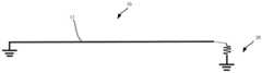
如图10所示,传输线10的外导体11的第一端(图中的右端)通过滤波器20接地,第二端(图中的左端)直接接地。其中,滤波器20可以是带通滤波器也可以是带阻滤波电路。As shown in FIG. 10 , the first end (right end in the figure) of the
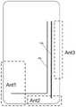
如图11所示,第一天线(ant1)需要通过第一传输线10a来传输低频信号,第二天线(ant2)需要通过第二传输线10b来传输中高频信号。其中,第二传输线10b的杂波影响到了第三天线(ant3)的低频信号。As shown in FIG. 11 , the first antenna (ant1) needs to transmit low frequency signals through the
如图12所示,此时可以考虑将第二传输线10b的一端进行滤波,如低阻高通。这样可以破坏原有的环形谐振结构,将基模杂波移除带外,同时,保证中高频信号的下地功能。As shown in FIG. 12 , at this time, one end of the
由于第二传输线10b的外导体11的一端通过滤波器下地,使得原有两端直接下地的环模被破坏,所以杂波的电流分布也会被破坏。新的边界条件由于引入了滤波器20这种对不同频率有不同表现的组件,因此会变得复杂。例如,外导体11只有一端下地,滤波器20会对所有频段开路,杂波的倍频会如图13所示。Because one end of the
请结合参阅图12和图13,第二传输线10b的杂波会在第一天线和第三天线上同时出现新的杂波,且呈奇次倍频。在这些杂波中,1次和3次倍频是低频附近的杂波,因此,需要偏移出低频。5次和7次倍频是中高频杂波,因此,需要移出中高频。一般来说,低频通带是700M-960M,中高频带通是1700M-2700M。由于加入的滤波器为带通滤波器,对于中高频(如1700M以上),则可以理解为下地。对于低频,可以理解为开路。开路时,杂波会以如图13所示。此时,假设基模在350M,则其3次倍频会是1050M,在更高频率下,5次及更高次模,由于滤波器的作用,会重新表现为如图5所示的环模下的杂波。Please refer to FIG. 12 and FIG. 13 in combination, the clutter of the
如图14所示,滤波器中不同容值大小的电容观察到不同杂波频移。当电容的容值越小时,杂波越往高频偏移;当电容的容值越大时,杂波越往低频偏移。As shown in Figure 14, different clutter frequency shifts are observed for capacitors with different capacitance values in the filter. When the capacitance of the capacitor is smaller, the clutter shifts to high frequencies; when the capacitance of the capacitor is larger, the clutter shifts to low frequencies.
如图15所示,由于去掉低频杂波的前提是不让第二天线带内产生新的杂波。这里5次倍频和7次倍频会落到第二天线带内,且从仿真结果来看7次倍频杂波对第二天线的影响较小。因此,需要选择合适的电容的容值使5次倍频偏移出第二天线带外。As shown in FIG. 15 , the premise of removing low-frequency clutter is to prevent new clutter from being generated in the second antenna band. Here, the 5th frequency multiplication and the 7th frequency multiplication will fall within the second antenna band, and from the simulation results, the 7th frequency multiplication clutter has little influence on the second antenna. Therefore, it is necessary to select an appropriate capacitance value to shift the 5th frequency multiplication out of the second antenna band.
这时3次倍频杂波会落入低频,因此,可以考虑在滤波器中增加电感。若增加电感下地,新增的电感会将低频调高,增加调谐范围。因此,可以将基模和3次倍频调到合适的位置,且新增的电感对于5次倍频和7次倍频杂波影响较小,可以忽略。At this time, the 3-fold frequency clutter will fall into the low frequency, so it can be considered to increase the inductance in the filter. If the inductance is added to the ground, the added inductance will increase the low frequency and increase the tuning range. Therefore, the fundamental mode and the 3rd frequency multiplication can be adjusted to appropriate positions, and the newly added inductance has little influence on the 5th frequency multiplication and the 7th frequency multiplication and can be ignored.
可以理解的是,在具体应用时,可以通过仿真的方式对滤波器的参数进行合理选择和调整,以实现对杂波的有效调谐。It can be understood that, in a specific application, the parameters of the filter can be reasonably selected and adjusted by means of simulation, so as to achieve effective tuning of the clutter.
另外,在上述的实施方式中,传输线10外导体11的单端通过带阻滤波器接地。其他的实施方式中,滤波器的类型、数量以及滤波器与传输线10外导体11之间的连接关系也可以是多样的。In addition, in the above-described embodiment, the single end of the
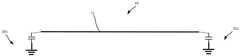
例如,如图16所示,在本申请提供另一个实施例中,传输线10的外导体11的第一端(图中的右端)可以通过第一带阻滤波器进行接地,传输线10的外导体11的第二端(图中的左端)可以通过第二带阻滤波器进行接地。即第一带阻滤波器中包含并联的电容和电感。第二滤波器中包含并联的电容和电感。For example, as shown in FIG. 16 , in another embodiment provided by the present application, the first end (the right end in the figure) of the
或者,如图17和图18所示,传输线10的外导体11的第二端(图中的右端)直接接地,传输线10的外导体11的第一端(图中的左端)可以通过带通滤波器进行接地。Alternatively, as shown in FIGS. 17 and 18 , the second end (the right end in the figure) of the
如图17所示,在具体实施时,带通滤波器可以是高通滤波器。即滤波器中包含电容,传输线10外导体11的第二端通过电容接地。As shown in FIG. 17 , in a specific implementation, the band-pass filter may be a high-pass filter. That is, the filter includes a capacitor, and the second end of the
如图18所示,在具体实施时,带通滤波器可以是低通滤波器。即滤波器中包含电感,传输线10外导体11的第二端通过电感接地。As shown in FIG. 18 , in a specific implementation, the band-pass filter may be a low-pass filter. That is, the filter includes an inductance, and the second end of the
或者,如图19和图20所示,传输线10的外导体11的第一端通过第一带通滤波器接地,传输线10的外导体11的第二端可以通过第二带通滤波器接地。Alternatively, as shown in FIGS. 19 and 20 , the first end of the
如图19所示,在具体实施时,第一带通滤波器可以是高通滤波器、第二带通滤波器可以是高通滤波器。即第一带通滤波器中包含电容,传输线10外导体11的第一端通过电容接地。As shown in FIG. 19 , in a specific implementation, the first band-pass filter may be a high-pass filter, and the second band-pass filter may be a high-pass filter. That is, the first bandpass filter includes a capacitor, and the first end of the
第二带通滤波器中包含电容,传输线10外导体11的第二端通过电容接地。The second bandpass filter includes a capacitor, and the second end of the
如图20所示,在具体实施时,第一带通滤波器可以是低通滤波器、第二带通滤波器可以是低通滤波器。即第一带通滤波器中包含电感,传输线10外导体11的第一端通过电感接地。As shown in FIG. 20 , in a specific implementation, the first band-pass filter may be a low-pass filter, and the second band-pass filter may be a low-pass filter. That is, the first bandpass filter includes an inductance, and the first end of the
第二带通滤波器中包含电感,传输线10外导体11的第二端通过电感接地。The second bandpass filter includes an inductance, and the second end of the
另外,本申请实施例还提供了一种天线组件,包括天线和线缆组件。In addition, an embodiment of the present application also provides an antenna assembly, including an antenna and a cable assembly.
在本申请提供的天线组件中,将传输线10通过滤波器接地,能够对传输线10工作频段以外的杂波进行调谐,以降低或避免杂波对传输线10附近的天线的效率所造成的影响。In the antenna assembly provided in the present application, the
在具体实施时,天线的设置数量以及设置位置可以根据不同需求进行适应性选择和调整,本申请对此不作限定。During specific implementation, the number of antennas to be installed and the installation positions can be adaptively selected and adjusted according to different requirements, which is not limited in this application.
例如,天线组件可以包括第一天线、第二天线、第一传输线10、第二传输线10。第一传输线10用于向第一天线传输射频信号,第二传输线10用于向第二天线传输射频信号。For example, the antenna assembly may include a first antenna, a second antenna, a
在具体实施时,第一天线的工作频段和第二天线的工作频段可以不同。例如,第一天线可以是用于产生低频信号的天线,第二天线可以是用于产生中高频信号的天线。During specific implementation, the working frequency band of the first antenna and the working frequency band of the second antenna may be different. For example, the first antenna may be an antenna for generating low frequency signals, and the second antenna may be an antenna for generating medium and high frequency signals.
可以理解的是,在其他的实施方式中,天线组件中还可以包括更多个天线以及传输线10,本申请对此不作具体限定。It can be understood that, in other embodiments, the antenna assembly may further include more antennas and
另外,本申请实施例还提供了一种移动终端,包括上述的天线组件。在实际应用时,移动终端可以是手机、平板电脑等。In addition, an embodiment of the present application further provides a mobile terminal, including the above-mentioned antenna assembly. In practical applications, the mobile terminal may be a mobile phone, a tablet computer, or the like.
在本申请提供的移动终端中,通过设置以上的天线组件,能够保证天线的辐射效率和信号传输质量,从而可以提升移动终端设备的品质一致性和使用效果。In the mobile terminal provided by the present application, by setting the above antenna components, the radiation efficiency and signal transmission quality of the antenna can be guaranteed, thereby improving the quality consistency and use effect of the mobile terminal device.
以上,仅为本申请的具体实施方式,但本申请的保护范围并不局限于此,任何熟悉本技术领域的技术人员在本申请揭露的技术范围内,可轻易想到变化或替换,都应涵盖在本申请的保护范围之内。因此,本申请的保护范围应以权利要求的保护范围为准。The above are only specific embodiments of the present application, but the protection scope of the present application is not limited to this. Any person skilled in the art can easily think of changes or replacements within the technical scope disclosed in the present application, and should cover within the scope of protection of this application. Therefore, the protection scope of the present application shall be subject to the protection scope of the claims.
Claims (10)
Translated fromChinesePriority Applications (4)
| Application Number | Priority Date | Filing Date | Title |
|---|---|---|---|
| CN202311134750.3ACN117154409A (en) | 2020-10-27 | 2021-08-17 | Transmission line assembly, antenna assembly and mobile terminal |
| US18/250,743US12381967B2 (en) | 2020-10-27 | 2021-09-08 | Transmission line assembly, antenna assembly, and mobile terminal |
| EP21884756.4AEP4216459A4 (en) | 2020-10-27 | 2021-09-08 | TRANSMISSION LINE ARRANGEMENT, ANTENNA ARRANGEMENT AND MOBILE TERMINAL |
| PCT/CN2021/117292WO2022089026A1 (en) | 2020-10-27 | 2021-09-08 | Transmission line assembly, antenna assembly, and mobile terminal |
Applications Claiming Priority (2)
| Application Number | Priority Date | Filing Date | Title |
|---|---|---|---|
| CN202022428861 | 2020-10-27 | ||
| CN2020224288613 | 2020-10-27 |
Related Child Applications (1)
| Application Number | Title | Priority Date | Filing Date |
|---|---|---|---|
| CN202311134750.3ADivisionCN117154409A (en) | 2020-10-27 | 2021-08-17 | Transmission line assembly, antenna assembly and mobile terminal |
Publications (2)
| Publication Number | Publication Date |
|---|---|
| CN114498041Atrue CN114498041A (en) | 2022-05-13 |
| CN114498041B CN114498041B (en) | 2023-09-22 |
Family
ID=81491536
Family Applications (1)
| Application Number | Title | Priority Date | Filing Date |
|---|---|---|---|
| CN202110943245.8AActiveCN114498041B (en) | 2020-10-27 | 2021-08-17 | Transmission line assembly, antenna assembly and mobile terminal |
Country Status (1)
| Country | Link |
|---|---|
| CN (1) | CN114498041B (en) |
Citations (25)
| Publication number | Priority date | Publication date | Assignee | Title |
|---|---|---|---|---|
| CN1198612A (en)* | 1997-03-12 | 1998-11-11 | 松下电器产业株式会社 | Shared antenna device |
| US6036546A (en)* | 1997-12-16 | 2000-03-14 | Filtec Filtertechnologie Fur Die Elektronikindustrie Gmbh | Adapter for connecting together two signal transmission lines each terminating in multiple connectors |
| US20010052830A1 (en)* | 2000-04-28 | 2001-12-20 | Kazushige Noguchi | Antenna duplexer with divided and grounded transmission line |
| US6538529B1 (en)* | 2000-08-16 | 2003-03-25 | Spx Corporation | Signal separator and bandpass filter |
| WO2007066272A2 (en)* | 2005-12-09 | 2007-06-14 | Koninklijke Philips Electronics N.V. | Antenna and device comprising an antenna |
| CN101065878A (en)* | 2004-11-30 | 2007-10-31 | 摩托罗拉公司 | Devices for delaying radio frequency signals |
| JP2009130453A (en)* | 2007-11-20 | 2009-06-11 | Hitachi Cable Ltd | Transmission line with filter function |
| CN102208710A (en)* | 2010-03-31 | 2011-10-05 | 安德鲁公司 | Structure for coupling grounding conversion from radio frequency coaxial cable to air microstrip and corresponding antenna |
| US20110279336A1 (en)* | 2010-05-17 | 2011-11-17 | David A Tonn | Modular VLF/LF And HF Buoyant Cable Antenna And Method |
| CN202259788U (en)* | 2011-08-16 | 2012-05-30 | 武汉凡谷电子技术股份有限公司 | Cavity filter hard connection signal input and output device |
| JP2013021592A (en)* | 2011-07-13 | 2013-01-31 | Murata Mfg Co Ltd | Antenna device and communication terminal device |
| CN202797278U (en)* | 2012-08-20 | 2013-03-13 | 富士康(昆山)电脑接插件有限公司 | Antenna assembly |
| CN104519952A (en)* | 2012-04-19 | 2015-04-15 | 默里蒂安医疗系统有限责任公司 | Heating/sensing catheter apparatus for minimally invasive applications |
| CN107004950A (en)* | 2014-10-21 | 2017-08-01 | At&T知识产权部有限合伙公司 | Method and device for transmitting electromagnetic waves |
| CN107851869A (en)* | 2015-06-25 | 2018-03-27 | At&T知识产权部有限合伙公司 | Method and apparatus for inducing nonfundamental modes on a transmission medium |
| CN107910622A (en)* | 2017-10-11 | 2018-04-13 | 南京邮电大学 | Areflexia band logical and low-pass filter based on transmission line structure |
| CN108023147A (en)* | 2017-12-29 | 2018-05-11 | 京信通信系统(中国)有限公司 | Combiner, phase shifter package and antenna |
| CN108242587A (en)* | 2016-12-23 | 2018-07-03 | 华为技术有限公司 | Antennas, lighting systems and communication systems |
| CN108470976A (en)* | 2018-04-11 | 2018-08-31 | 西安交通大学 | A kind of W-waveband microfilter antenna based on rectangular coaxial cable architecture |
| CN109980364A (en)* | 2019-02-28 | 2019-07-05 | 华为技术有限公司 | A kind of Anneta module, antenna assembly and terminal device |
| CN209183694U (en)* | 2018-12-29 | 2019-07-30 | 京信通信技术(广州)有限公司 | Multi-frequency base station antenna, feeder network system and filter |
| CN110085986A (en)* | 2019-06-25 | 2019-08-02 | 东南大学 | It is a kind of can the big frequency of beam scanning compare dual-band antenna |
| US20190296415A1 (en)* | 2018-03-20 | 2019-09-26 | Commscope Italy S.R.L. | Low loss radio frequency transmission lines and devices including such transmission lines |
| US20190363748A1 (en)* | 2018-05-23 | 2019-11-28 | Qualcomm Incorporated | Integrated Passive Device Transmission-Line Resonator |
| US20190379110A1 (en)* | 2018-06-08 | 2019-12-12 | Wistron Neweb Corporation | Antenna structure |
- 2021
- 2021-08-17CNCN202110943245.8Apatent/CN114498041B/enactiveActive
Patent Citations (25)
| Publication number | Priority date | Publication date | Assignee | Title |
|---|---|---|---|---|
| CN1198612A (en)* | 1997-03-12 | 1998-11-11 | 松下电器产业株式会社 | Shared antenna device |
| US6036546A (en)* | 1997-12-16 | 2000-03-14 | Filtec Filtertechnologie Fur Die Elektronikindustrie Gmbh | Adapter for connecting together two signal transmission lines each terminating in multiple connectors |
| US20010052830A1 (en)* | 2000-04-28 | 2001-12-20 | Kazushige Noguchi | Antenna duplexer with divided and grounded transmission line |
| US6538529B1 (en)* | 2000-08-16 | 2003-03-25 | Spx Corporation | Signal separator and bandpass filter |
| CN101065878A (en)* | 2004-11-30 | 2007-10-31 | 摩托罗拉公司 | Devices for delaying radio frequency signals |
| WO2007066272A2 (en)* | 2005-12-09 | 2007-06-14 | Koninklijke Philips Electronics N.V. | Antenna and device comprising an antenna |
| JP2009130453A (en)* | 2007-11-20 | 2009-06-11 | Hitachi Cable Ltd | Transmission line with filter function |
| CN102208710A (en)* | 2010-03-31 | 2011-10-05 | 安德鲁公司 | Structure for coupling grounding conversion from radio frequency coaxial cable to air microstrip and corresponding antenna |
| US20110279336A1 (en)* | 2010-05-17 | 2011-11-17 | David A Tonn | Modular VLF/LF And HF Buoyant Cable Antenna And Method |
| JP2013021592A (en)* | 2011-07-13 | 2013-01-31 | Murata Mfg Co Ltd | Antenna device and communication terminal device |
| CN202259788U (en)* | 2011-08-16 | 2012-05-30 | 武汉凡谷电子技术股份有限公司 | Cavity filter hard connection signal input and output device |
| CN104519952A (en)* | 2012-04-19 | 2015-04-15 | 默里蒂安医疗系统有限责任公司 | Heating/sensing catheter apparatus for minimally invasive applications |
| CN202797278U (en)* | 2012-08-20 | 2013-03-13 | 富士康(昆山)电脑接插件有限公司 | Antenna assembly |
| CN107004950A (en)* | 2014-10-21 | 2017-08-01 | At&T知识产权部有限合伙公司 | Method and device for transmitting electromagnetic waves |
| CN107851869A (en)* | 2015-06-25 | 2018-03-27 | At&T知识产权部有限合伙公司 | Method and apparatus for inducing nonfundamental modes on a transmission medium |
| CN108242587A (en)* | 2016-12-23 | 2018-07-03 | 华为技术有限公司 | Antennas, lighting systems and communication systems |
| CN107910622A (en)* | 2017-10-11 | 2018-04-13 | 南京邮电大学 | Areflexia band logical and low-pass filter based on transmission line structure |
| CN108023147A (en)* | 2017-12-29 | 2018-05-11 | 京信通信系统(中国)有限公司 | Combiner, phase shifter package and antenna |
| US20190296415A1 (en)* | 2018-03-20 | 2019-09-26 | Commscope Italy S.R.L. | Low loss radio frequency transmission lines and devices including such transmission lines |
| CN108470976A (en)* | 2018-04-11 | 2018-08-31 | 西安交通大学 | A kind of W-waveband microfilter antenna based on rectangular coaxial cable architecture |
| US20190363748A1 (en)* | 2018-05-23 | 2019-11-28 | Qualcomm Incorporated | Integrated Passive Device Transmission-Line Resonator |
| US20190379110A1 (en)* | 2018-06-08 | 2019-12-12 | Wistron Neweb Corporation | Antenna structure |
| CN209183694U (en)* | 2018-12-29 | 2019-07-30 | 京信通信技术(广州)有限公司 | Multi-frequency base station antenna, feeder network system and filter |
| CN109980364A (en)* | 2019-02-28 | 2019-07-05 | 华为技术有限公司 | A kind of Anneta module, antenna assembly and terminal device |
| CN110085986A (en)* | 2019-06-25 | 2019-08-02 | 东南大学 | It is a kind of can the big frequency of beam scanning compare dual-band antenna |
Also Published As
| Publication number | Publication date |
|---|---|
| CN114498041B (en) | 2023-09-22 |
Similar Documents
| Publication | Publication Date | Title |
|---|---|---|
| Ahmed et al. | Ultra-wideband bandpass filter based on composite right/left handed transmission-line unit-cell | |
| US11063330B2 (en) | Filter | |
| WO2020088620A1 (en) | Dielectric filter and communication device | |
| CN106887656A (en) | A kind of miniaturization Wide stop bands ultra-wide band filter with double trap characteristics | |
| CN110247143B (en) | A switchable and tunable microstrip bandpass filter | |
| WO2021136187A1 (en) | Array antenna and communication device | |
| CN1945899A (en) | Micro strip antenna | |
| CN202434677U (en) | High pass filter | |
| CN208385587U (en) | A kind of small-sized three band-pass filter with eight transmission zeros | |
| CN105449326B (en) | The microwave filter and its design method of the wide suppression of high selectivity | |
| CN208315717U (en) | Using the small sized double frequency bandpass filter of minor matters load bending type defected microstrip structure | |
| CN212434808U (en) | Filter Structures and Filters | |
| CN114498041B (en) | Transmission line assembly, antenna assembly and mobile terminal | |
| CN209981435U (en) | Microstrip band-pass filter of WLAN frequency channel | |
| WO2022089026A1 (en) | Transmission line assembly, antenna assembly, and mobile terminal | |
| US8248191B2 (en) | Microstrip filter | |
| KR101216433B1 (en) | High-pass filter using metameterial | |
| TWI483453B (en) | Noise filtering circuit for suppressing emi | |
| WO2020252678A1 (en) | Filter cable | |
| CN113811960B (en) | Filter Cable | |
| CN110190369B (en) | Wide-stop-band microwave filter based on coplanar waveguide | |
| CN109786906B (en) | Filter based on coplanar waveguide transmission line | |
| US7683743B2 (en) | Filtering circuit and structure thereof | |
| CN223093094U (en) | Band-pass filter of asymmetric SIR | |
| CN117691965B (en) | Filter containing half-mode substrate coaxial resonator |
Legal Events
| Date | Code | Title | Description |
|---|---|---|---|
| PB01 | Publication | ||
| PB01 | Publication | ||
| SE01 | Entry into force of request for substantive examination | ||
| SE01 | Entry into force of request for substantive examination | ||
| GR01 | Patent grant | ||
| GR01 | Patent grant |