CN114495441A - Combustible gas detector gas filling detection device and detection method - Google Patents
Combustible gas detector gas filling detection device and detection methodDownload PDFInfo
- Publication number
- CN114495441A CN114495441ACN202210017131.5ACN202210017131ACN114495441ACN 114495441 ACN114495441 ACN 114495441ACN 202210017131 ACN202210017131 ACN 202210017131ACN 114495441 ACN114495441 ACN 114495441A
- Authority
- CN
- China
- Prior art keywords
- combustible gas
- alarm time
- alarm
- detector
- gas
- Prior art date
- Legal status (The legal status is an assumption and is not a legal conclusion. Google has not performed a legal analysis and makes no representation as to the accuracy of the status listed.)
- Granted
Links
Images
Classifications
- G—PHYSICS
- G08—SIGNALLING
- G08B—SIGNALLING OR CALLING SYSTEMS; ORDER TELEGRAPHS; ALARM SYSTEMS
- G08B21/00—Alarms responsive to a single specified undesired or abnormal condition and not otherwise provided for
- G08B21/02—Alarms for ensuring the safety of persons
- G08B21/12—Alarms for ensuring the safety of persons responsive to undesired emission of substances, e.g. pollution alarms
- G08B21/16—Combustible gas alarms
- G—PHYSICS
- G08—SIGNALLING
- G08B—SIGNALLING OR CALLING SYSTEMS; ORDER TELEGRAPHS; ALARM SYSTEMS
- G08B5/00—Visible signalling systems, e.g. personal calling systems, remote indication of seats occupied
- G08B5/22—Visible signalling systems, e.g. personal calling systems, remote indication of seats occupied using electric transmission; using electromagnetic transmission
- G08B5/36—Visible signalling systems, e.g. personal calling systems, remote indication of seats occupied using electric transmission; using electromagnetic transmission using visible light sources
- Y—GENERAL TAGGING OF NEW TECHNOLOGICAL DEVELOPMENTS; GENERAL TAGGING OF CROSS-SECTIONAL TECHNOLOGIES SPANNING OVER SEVERAL SECTIONS OF THE IPC; TECHNICAL SUBJECTS COVERED BY FORMER USPC CROSS-REFERENCE ART COLLECTIONS [XRACs] AND DIGESTS
- Y02—TECHNOLOGIES OR APPLICATIONS FOR MITIGATION OR ADAPTATION AGAINST CLIMATE CHANGE
- Y02E—REDUCTION OF GREENHOUSE GAS [GHG] EMISSIONS, RELATED TO ENERGY GENERATION, TRANSMISSION OR DISTRIBUTION
- Y02E60/00—Enabling technologies; Technologies with a potential or indirect contribution to GHG emissions mitigation
- Y02E60/30—Hydrogen technology
- Y02E60/32—Hydrogen storage
Landscapes
- Physics & Mathematics (AREA)
- Engineering & Computer Science (AREA)
- General Physics & Mathematics (AREA)
- Health & Medical Sciences (AREA)
- Environmental & Geological Engineering (AREA)
- General Health & Medical Sciences (AREA)
- Toxicology (AREA)
- Business, Economics & Management (AREA)
- Emergency Management (AREA)
- Chemical & Material Sciences (AREA)
- Combustion & Propulsion (AREA)
- Electromagnetism (AREA)
- Investigating Or Analyzing Materials By The Use Of Electric Means (AREA)
Abstract
Description
Translated fromChinese技术领域technical field
本发明涉及可燃气体安全防护技术领域,具体涉及一种可燃气体探测器加气检测装置及检测方法。The invention relates to the technical field of combustible gas safety protection, in particular to a gas filling detection device and a detection method for a combustible gas detector.
背景技术Background technique
随着时代的进步,天然气、液化石油气等可燃气体在现代建筑中使用越来越多,而因可燃气体泄漏导致的爆燃、爆炸事故频发,严重威胁人民群众的生命和财产安全。因此我国在工业建筑、公共建筑厨房、及家庭厨房等使用可燃气体的地方广泛推广了可燃气体探测器(燃气报警器)。可燃气体探测器可以有效的早期探测可燃气体的泄漏,对相关人员做出预警,从而有效的避免爆燃、爆炸等火灾危险事故的发生。With the progress of the times, natural gas, liquefied petroleum gas and other flammable gases are used more and more in modern buildings, and the frequent deflagration and explosion accidents caused by the leakage of flammable gases have seriously threatened people's lives and property safety. Therefore, flammable gas detectors (gas alarms) have been widely promoted in industrial buildings, public building kitchens, and home kitchens where flammable gas is used. The combustible gas detector can effectively detect the leakage of combustible gas at an early stage, and give early warning to relevant personnel, so as to effectively avoid the occurrence of fire hazards such as deflagration and explosion.
然而,可燃气体探测器在长期使用过程中可能因污损、老化、故障等各种原因失效,因此需要定期对可燃气体探测器的有效性进行试验。目前现有产品,只有便携式可燃气体探测器,其效果与固定式可燃气体探测器是一样的,只能起到探测是否有可燃气体泄漏的作用,不能起到检测各种可燃气体探测器有效性的作用。因此,有必要设计一种可燃气体探测器加气检测装置。However, combustible gas detectors may fail due to various reasons such as contamination, aging, and failure during long-term use. Therefore, it is necessary to regularly test the effectiveness of combustible gas detectors. At present, there are only portable combustible gas detectors, which have the same effect as fixed combustible gas detectors. They can only detect whether there is a combustible gas leak, but cannot detect the effectiveness of various combustible gas detectors. effect. Therefore, it is necessary to design a gas-filled detection device for a combustible gas detector.
发明内容SUMMARY OF THE INVENTION
本发明提供了一种可燃气体探测器加气检测装置及检测方法,目的是对可燃气体探测器的使用状态进行准确检测,从而提高燃气使用的安全保障。The invention provides a gas filling detection device and a detection method for a combustible gas detector, which aim to accurately detect the use state of the combustible gas detector, thereby improving the safety guarantee of gas use.
为达到上述目的,本发明所采用的技术方案是:In order to achieve the above object, the technical scheme adopted in the present invention is:
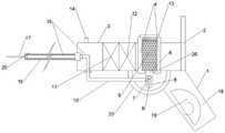
一种可燃气体探测器加气检测装置,包括壳体,所述的壳体的后部设有贯通壳体上下端的安装筒,所述的安装筒内卡接有用以盛装可燃气体样气的气瓶,所述的气瓶的底部设有贯穿安装筒下表面的出气管,所述的出气管上设有球阀,所述球阀外侧端固定连接有拉杆,拉杆的底部设有拉孔,所述的出气管输出端连接有接管,所述的接管连接有软通气管,所述的软通气管的外表面套接有金属定型软管,在软通气管的末端连接有喷气针;所述的拉杆远离喷气针一侧的壳体外表面固定设有把手;所述的金属定型软管的末端外表面固定设有第一可燃气体传感器,所述壳体朝向喷气针一端的外表面设有第二可燃气体传感器,在壳体内还设有相互电连接的蓄电池和控制器,壳体远离喷气针的一端还固定设有人机交互装置,位于壳体朝向把手一侧的侧壁外表面设有定时控制按钮,所述的定时控制按钮、人机交互装置分别通过导线与控制器电性连接,所述的第一可燃气体传感器及第二可燃气体传感器分别通过导线与控制器信号连接,所述的控制器内设有计时模块及检测数据分析处理模块。A gas-filling detection device for a combustible gas detector, comprising a casing, the rear part of the casing is provided with a mounting cylinder penetrating the upper and lower ends of the casing, and a gas for holding a combustible gas sample gas is clamped in the mounting cylinder. The bottom of the gas cylinder is provided with an air outlet pipe running through the lower surface of the installation cylinder, the air outlet pipe is provided with a ball valve, the outer end of the ball valve is fixedly connected with a pull rod, and the bottom of the pull rod is provided with a pull hole, the The output end of the air outlet pipe is connected with a pipe, the pipe is connected with a soft air pipe, the outer surface of the soft air pipe is sleeved with a metal shaped hose, and the end of the soft air pipe is connected with a jet needle; the A handle is fixed on the outer surface of the casing on the side of the draw rod away from the jet needle; a first combustible gas sensor is fixed on the outer surface of the end of the metal shaped hose, and a second combustible gas sensor is fixed on the outer surface of the end of the casing facing the jet needle The combustible gas sensor is also provided with a battery and a controller that are electrically connected to each other in the casing. The end of the casing away from the jet needle is also fixed with a human-computer interaction device, and the outer surface of the side wall on the side of the casing facing the handle is provided with a timing control button, the timing control button and the human-computer interaction device are respectively electrically connected to the controller through wires, and the first combustible gas sensor and the second combustible gas sensor are signally connected to the controller through wires, respectively. The device is provided with a timing module and a detection data analysis and processing module.
优选的,所述的壳体内的前端预留有用以盛放多余软通气管的空腔,所述的空腔底部设有贯通壳体外表面的连接管,所述的接管的一端与出气管的输出端连接,另一端通过连接管与软通气管的端部密封固定连接,所述的壳体远离安装筒的一端设有接口,所述的接口的外侧端固定设有第一金属定型软管固定座,所述的软通气管的端部穿过接口及第一金属定型软管固定座向外延伸,在软通气管的末端远离喷气针的一侧还设有第二金属定型软管固定座,所述的金属定型软管的两端分别与第一金属定型软管固定座、第二金属定型软管固定座固定连接,所述的软通气管位于壳体外的长度与金属定型软管的长度相配,所述的软通气管分别与接口及第一金属定型软管固定座间隙配合。Preferably, the front end of the casing is reserved with a cavity for holding excess flexible air pipes, the bottom of the cavity is provided with a connecting pipe penetrating the outer surface of the casing, and one end of the connecting pipe is connected to the air outlet pipe. The output end is connected, and the other end is sealed and fixedly connected with the end of the flexible air pipe through a connecting pipe. The end of the casing away from the installation cylinder is provided with an interface, and the outer end of the interface is fixed with a first metal shaped hose. A fixing seat, the end of the flexible air pipe extends outward through the interface and the first metal shaped hose fixing seat, and a second metal shaped hose is also provided on the side of the end of the flexible air pipe away from the jet needle for fixing The two ends of the metal shaped hose are respectively fixedly connected with the first metal shaped hose fixing seat and the second metal shaped hose fixing seat, and the length of the soft air pipe outside the shell is the same as the metal shaped hose. The length of the flexible air pipe is matched with the interface and the first metal shaped hose fixing seat respectively.
优选的,所述的出气管及拉杆的外侧还设有弧形防护板,所述的弧形防护板的两端分别与壳体外表面及把手前端固定连接。Preferably, the outer side of the air outlet pipe and the pull rod is further provided with an arc-shaped protective plate, and the two ends of the arc-shaped protective plate are respectively fixedly connected with the outer surface of the casing and the front end of the handle.
优选的,所述的安装筒的上端口设有内螺纹,并螺接有旋盖,所述的旋盖旋紧时将气瓶固定在安装筒内。Preferably, the upper port of the installation cylinder is provided with an inner thread, and is screwed with a screw cap, and when the screw cap is screwed, the gas cylinder is fixed in the installation cylinder.
优选的,所述的把手内设有储存室,在把手的底端设有用以将储存室封闭的封盖,在储存室内部储存有防护面罩。Preferably, the handle is provided with a storage chamber, the bottom end of the handle is provided with a cover for closing the storage chamber, and a protective mask is stored inside the storage chamber.
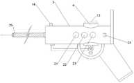
优选的,所述的壳体侧壁外表面还沿壳体的轴线分别设有提示灯、警示灯、报警灯,所述的提示灯、警示灯、报警灯分别通过导线与控制器电性连接。Preferably, the outer surface of the side wall of the casing is also provided with a prompt light, a warning light and an alarm light respectively along the axis of the shell, and the prompt light, the warning light and the alarm light are respectively electrically connected to the controller through wires. .
优选的,所述的人机交互装置上设有数据输入模块。Preferably, the human-computer interaction device is provided with a data input module.
一种可燃气体探测器加气检测方法,包括如下步骤:A flammable gas detector gas filling detection method, comprising the following steps:
S1、检测人员打开封盖,取出防护面罩,并佩戴好,之后根据可燃气体探测器所在的位置及周边管道的情况,将金属定型软管弯曲成所需形状,并手持把手,将喷气针的喷气口与可燃气体探测器的工作端相对;S1. The inspector opens the cover, takes out the protective mask, and wears it. Then, according to the position of the combustible gas detector and the surrounding pipeline, bend the metal forming hose into the required shape, and hold the handle, put the air needle The air jet is opposite to the working end of the combustible gas detector;
S2、打开定时控制按钮,在控制器的控制下探测器开始处于工作状态,然后打开球阀并同时按压定时控制按钮,样气从喷气针输出,控制器通过计时模块开始计时;S2. Turn on the timing control button, the detector starts to work under the control of the controller, then open the ball valve and press the timing control button at the same time, the sample gas is output from the jet needle, and the controller starts timing through the timing module;
S3、当所检测的可燃气体探测器发出报警音时,立即按压定时控制按钮,控制器对报警时间A进行记录;同时,当第一可燃气体传感器及第二可燃气体传感器报警时,控制器也依次对报警时间B及报警时间C进行记录,并针对报警时间A、报警时间B及报警时间C,通过检测数据分析处理模块进行分析处理,并对可燃气体探测器的工作状态及该工作状态对环境安全的影响进行评估,评估结果在人机交互装置的显示界面显示;S3. When the detected combustible gas detector emits an alarm sound, immediately press the timing control button, and the controller records the alarm time A; at the same time, when the first combustible gas sensor and the second combustible gas sensor alarm, the controller also sequentially The alarm time B and the alarm time C are recorded, and the alarm time A, the alarm time B and the alarm time C are analyzed and processed through the detection data analysis and processing module, and the working state of the combustible gas detector and the effect of the working state on the environment are analyzed and processed. The impact of safety is evaluated, and the evaluation results are displayed on the display interface of the human-computer interaction device;
S4、当提示灯亮时,意味着检测环境中有微量安全范围内的可燃气体,检测人员可继续检测;当警示灯亮时,意味着检测环境中可燃气体含量逼近安全阈值,检测人员需及时停止检测;当报警灯亮时,意味着检测环境中的可燃气体含量超过安全阈值,检测人员必须停止检测,并做相应处理;在以上原则的基础上,当报警时间A早于或等于报警时间B时或者报警时间A晚于报警时间C时,检测人员需在听到可燃气体探测器的报警音后停止检测,并控制球阀关闭;当报警时间A位于报警时间B和报警时间C之间时,检测人员在第二可燃气体传感器发出报警后停止检测;当可燃气体探测器超过设定时间未发出报警音时,检测人员应停止检测。S4. When the warning light is on, it means that there is a trace amount of combustible gas within the safe range in the detection environment, and the inspector can continue to detect; when the warning light is on, it means that the content of combustible gas in the inspection environment is approaching the safety threshold, and the inspector needs to stop the inspection in time ; When the alarm light is on, it means that the combustible gas content in the detection environment exceeds the safety threshold, and the detection personnel must stop the detection and take corresponding measures; on the basis of the above principles, when the alarm time A is earlier than or equal to the alarm time B or When the alarm time A is later than the alarm time C, the inspection personnel need to stop the inspection after hearing the alarm sound of the combustible gas detector, and control the ball valve to close; when the alarm time A is between the alarm time B and the alarm time C, the inspection personnel Stop the detection after the second combustible gas sensor gives an alarm; when the combustible gas detector does not emit an alarm sound for a set time, the inspector should stop the detection.
优选的,所述的S1中,金属定型软管定型后,测量喷气针的喷气口至第二可燃气体传感器的感应端之间的距离,并将该距离的数值通过数据输入模块输入;所述的S3中,对可燃气体探测器的工作状态进行评估的方法为:确保第一可燃气体传感器功能正常,使第一可燃气体传感器达到报警阈值的可燃气体浓度与可燃气体探测器的报警阈值的可燃气体浓度相同,以报警时间B为基点,计算报警时间A与报警时间B之间的差值,以此来确定可燃气体探测器的延迟报警时间,依据延迟报警时间的长短评估可燃气体探测器的工作状态;所述的S3中,依据可燃气体探测器的工作状态对环境安全的影响进行评估的方法为:计算报警时间B与报警时间C之间的差值,并结合所输入的距离的数值计算可燃气体在检测方向上的扩散速度,以扩散速度为基准,结合可燃气体探测器的延迟报警时间,计算在延迟报警时间内可燃气体在测量方向上的扩散范围,并以扩散范围的大小评估可燃气体探测器的工作状态对环境安全的影响。Preferably, in the S1, after the metal shaped hose is shaped, the distance between the air injection port of the air injection needle and the sensing end of the second combustible gas sensor is measured, and the value of this distance is input through the data input module; In S3, the method for evaluating the working state of the combustible gas detector is: ensuring that the first combustible gas sensor functions normally, so that the first combustible gas sensor reaches the combustible gas concentration of the alarm threshold and the combustible gas concentration of the alarm threshold of the combustible gas detector. The gas concentration is the same. Taking the alarm time B as the base point, the difference between the alarm time A and the alarm time B is calculated to determine the delayed alarm time of the combustible gas detector. Working state; in the described S3, the method for evaluating the impact of the working state of the combustible gas detector on environmental safety is: calculating the difference between the alarm time B and the alarm time C, and combining the input value of the distance Calculate the diffusion speed of the combustible gas in the detection direction, take the diffusion speed as the benchmark, combine with the delay alarm time of the combustible gas detector, calculate the diffusion range of the combustible gas in the measurement direction within the delay alarm time, and evaluate the size of the diffusion range The influence of the working state of the combustible gas detector on the environmental safety.
优选的,所述的S3中,对环境安全的影响进行评估的方法中,选择无风环境进行检测,以可燃气体自然扩散的速度为基准进行评估。Preferably, in said S3, in the method for evaluating the impact on environmental safety, a windless environment is selected for detection, and the evaluation is performed on the basis of the natural diffusion rate of combustible gas.
本发明一种可燃气体探测器加气检测装置的有益效果为:本发明可对各种复杂位置安装的可燃气体探测器进行加气检测,并可对可燃气体探测器的工作状态及对环境安全的影响进行精确评估,从而使可燃气体的使用更安全更可靠,避免可燃气体探测器元器件老化带来的安全隐患。The beneficial effects of the gas refueling detection device for the combustible gas detector of the present invention are as follows: the present invention can perform refueling detection on the combustible gas detectors installed in various complex positions, and can check the working state of the combustible gas detector and the safety of the environment. The impact of the flammable gas can be accurately evaluated, so as to make the use of flammable gas safer and more reliable, and avoid the potential safety hazards caused by the aging of the components of the flammable gas detector.
附图说明:Description of drawings:
图1、本发明的剖视结构示意图;Fig. 1, the sectional structure schematic diagram of the present invention;
图2、本发明的正面结构示意图;Fig. 2, the front structure schematic diagram of the present invention;
1、把手;2、人机交互装置;3、壳体;4、安装筒;5、气瓶;6、出气管;7、球阀;8、拉杆;9、拉孔;10、接管;11、蓄电池;12、控制器;13、旋盖;14、第二可燃气体传感器;15、软通气管;16、金属定型软管;17、喷气针;18、储存室;19、防护面罩;20、弧形防护板;21、提示灯;22、警示灯;23、报警灯;24、定时控制按钮;25、第一可燃气体传感器;26、通孔。1. Handle; 2. Human-computer interaction device; 3. Housing; 4. Installation cylinder; 5. Gas cylinder; 6. Outlet pipe; 7. Ball valve; 8. Pull rod; 9. Pull hole; 10. Take over; 11. battery; 12, controller; 13, screw cap; 14, second combustible gas sensor; 15, soft air pipe; 16, metal shaped hose; 17, jet needle; 18, storage room; 19, protective mask; 20, Arc-shaped protective plate; 21, prompt light; 22, warning light; 23, alarm light; 24, timing control button; 25, first combustible gas sensor; 26, through hole.
具体实施方式:Detailed ways:
以下所述,是以阶梯递进的方式对本发明的实施方式详细说明,该说明仅为本发明的较佳实施例而已,并非用于限定本发明的保护范围,凡在本发明的精神和原则之内所作的任何修改、等同替换和改进等,均应包含在本发明的保护范围之内。The following describes the embodiments of the present invention in a step-by-step manner. This description is only a preferred embodiment of the present invention, and is not intended to limit the protection scope of the present invention. Anything within the spirit and principle of the present invention Any modifications, equivalent replacements and improvements made within the scope of the present invention should be included within the protection scope of the present invention.
本发明的描述中,需要说明的是,术语“上”“下”“左”“右”“顶”“底”“内”“外”等指示的方位或位置关系为基于附图所示的方位或位置关系,仅是为了描述本发明和简化描述,而不是指示或暗示所指的装置或元件必须具有特定的方位、以及特定的方位构造和操作,因此不能理解为对本发明的限制。In the description of the present invention, it should be noted that the orientation or positional relationship indicated by the terms "upper", "lower", "left", "right", "top", "bottom", "inside", "outside", etc. are based on those shown in the accompanying drawings. The orientation or positional relationship is only for describing the present invention and simplifying the description, rather than indicating or implying that the indicated device or element must have a specific orientation, as well as a specific orientation configuration and operation, and therefore should not be construed as a limitation of the present invention.
实施例1、Embodiment 1,
一种可燃气体探测器加气检测装置,如图1、2所示,包括壳体3,所述的壳体3的后部设有贯通壳体上下端的安装筒4,所述的安装筒4内卡接有用以盛装可燃气体样气的气瓶5,所述的气瓶5的底部设有贯穿安装筒下表面的出气管6,所述的出气管6上设有球阀7,所述球阀7外侧端固定连接有拉杆8,拉杆8的底部设有拉孔9,所述的出气管6输出端连接有接管10,所述的接管10连接有软通气管15,所述的软通气管15的外表面套接有金属定型软管16,在软通气管15的末端连接有喷气针17;所述的拉杆8远离喷气针一侧的壳体外表面固定设有把手1;所述的金属定型软管16的末端外表面固定设有第一可燃气体传感器25,所述壳体朝向喷气针一端的外表面设有第二可燃气体传感器14,在壳体内还设有相互电连接的蓄电池11和控制器12,壳体远离喷气针的一端还固定设有人机交互装置2,位于壳体朝向把手一侧的侧壁外表面设有定时控制按钮24,所述的定时控制按钮24、人机交互装置2分别通过导线与控制器电性连接,所述的第一可燃气体传感器25及第二可燃气体传感器14分别通过导线与控制器信号连接,所述的控制器内设有计时模块及检测数据分析处理模块。A gas filling detection device for a combustible gas detector, as shown in Figures 1 and 2, includes a
如图1、2所示,所述的壳体内的前端预留有用以盛放多余软通气管15的空腔,所述的空腔底部设有贯通壳体外表面的连接管(图中未标示),所述的接管10的一端与出气管6的输出端连接,另一端通过连接管与软通气管15的端部密封固定连接,所述的壳体远离安装筒4的一端设有接口,所述的接口的外侧端固定设有第一金属定型软管固定座,所述的软通气管15的端部穿过接口及第一金属定型软管固定座向外延伸,在软通气管15的末端远离喷气针的一侧还设有第二金属定型软管固定座,所述的金属定型软管16的两端分别与第一金属定型软管固定座、第二金属定型软管固定座固定连接,所述的软通气管15位于壳体外的长度与金属定型软管16的长度相配,所述的软通气管15分别与接口及第一金属定型软管固定座间隙配合。As shown in Figures 1 and 2, the front end of the casing is reserved with a cavity for holding the excess
如图1、2所示,所述的出气管6及拉杆8的外侧还设有弧形防护板20,所述的弧形防护板20的两端分别与壳体外表面及把手前端固定连接。As shown in Figures 1 and 2, the outer side of the
如图1、2所示,所述的安装筒4的上端口设有内螺纹,并螺接有旋盖13,所述的旋盖13旋紧时将气瓶5固定在安装筒4内。As shown in FIGS. 1 and 2 , the upper port of the installation cylinder 4 is provided with an internal thread, and is screwed with a
如图1、2所示,所述的把手1内设有储存室18,在把手1的底端设有用以将储存室封闭的封盖,在储存室18内部储存有防护面罩19。As shown in FIGS. 1 and 2 , the handle 1 is provided with a
如图1、2所示,所述的壳体侧壁外表面还沿壳体的轴线分别设有提示灯21、警示灯22、报警灯23,所述的提示灯21、警示灯22、报警灯23分别通过导线与控制器电性连接。As shown in Figures 1 and 2, the outer surface of the side wall of the casing is also provided with a
所述的人机交互装置上设有数据输入模块(图中未画出)。The human-computer interaction device is provided with a data input module (not shown in the figure).
实施例2、
在实施例1的基础上,本实施例公开了一种可燃气体探测器加气检测方法,包括如下步骤:On the basis of Embodiment 1, this embodiment discloses a method for detecting gas addition of a combustible gas detector, which includes the following steps:
S1、检测人员打开封盖,取出防护面罩,并佩戴好,之后根据可燃气体探测器所在的位置及周边管道的情况,将金属定型软管弯曲成所需形状,并手持把手1,将喷气针的喷气口与可燃气体探测器的工作端相对;S1. The inspector opens the cover, takes out the protective mask, and wears it. Then, according to the position of the combustible gas detector and the condition of the surrounding pipeline, the metal forming hose is bent into the required shape, and holding the handle 1, the jet needle The jet port is opposite to the working end of the combustible gas detector;
S2、打开定时控制按钮24,在控制器的控制下探测器开始处于工作状态,然后打开球阀7并同时按压定时控制按钮24,样气从喷气针输出,控制器通过计时模块开始计时;S2, open the
S3、当所检测的可燃气体探测器发出报警音时,立即按压定时控制按钮24,控制器对报警时间A进行记录;同时,当第一可燃气体传感器25及第二可燃气体传感器14报警时,控制器也依次对报警时间B及报警时间C进行记录,并针对报警时间A、报警时间B及报警时间C,通过检测数据分析处理模块进行分析处理,并对可燃气体探测器的工作状态及该工作状态对环境安全的影响进行评估,评估结果在人机交互装置的显示界面显示;S3. When the detected combustible gas detector emits an alarm sound, immediately press the
S4、当提示灯亮时,意味着检测环境中有微量安全范围内的可燃气体,检测人员可继续检测;当警示灯亮时,意味着检测环境中可燃气体含量逼近安全阈值,检测人员需及时停止检测;当报警灯亮时,意味着检测环境中的可燃气体含量超过安全阈值,检测人员必须停止检测,并做相应处理;在以上原则的基础上,当报警时间A早于或等于报警时间B时(使用状态正常)或者报警时间A晚于报警时间C时,检测人员需在听到可燃气体探测器的报警音后停止检测,并控制球阀关闭;当报警时间A位于报警时间B和报警时间C之间时,检测人员在第二可燃气体传感器发出报警后停止检测,目的是对燃气扩散速度的相关数据进行收集;当可燃气体探测器超过设定时间未发出报警音时,检测人员应停止检测。S4. When the warning light is on, it means that there is a trace amount of combustible gas within the safe range in the detection environment, and the inspector can continue to detect; when the warning light is on, it means that the content of combustible gas in the inspection environment is approaching the safety threshold, and the inspector needs to stop the inspection in time ; When the alarm light is on, it means that the combustible gas content in the detection environment exceeds the safety threshold, and the detection personnel must stop the detection and take corresponding measures; on the basis of the above principles, when the alarm time A is earlier than or equal to the alarm time B ( When the use status is normal) or the alarm time A is later than the alarm time C, the inspector needs to stop the inspection after hearing the alarm sound of the combustible gas detector, and control the ball valve to close; when the alarm time A is between the alarm time B and the alarm time C After the second combustible gas sensor gives an alarm, the inspector stops the inspection, in order to collect the relevant data of the gas diffusion rate; when the combustible gas detector does not emit an alarm sound after the set time, the inspector should stop the inspection.
实施例3、
在实施例2的基础上,本实施例进一步改进为:On the basis of
所述的S1中,金属定型软管定型后,测量喷气针的喷气口至第二可燃气体传感器14的感应端之间的距离,并将该距离的数值通过数据输入模块输入;所述的S3中,对可燃气体探测器的工作状态进行评估的方法为:确保第一可燃气体传感器25功能正常,使第一可燃气体传感器25达到报警阈值的可燃气体浓度与可燃气体探测器的报警阈值的可燃气体浓度相同,以报警时间B为基点,计算报警时间A与报警时间B之间的差值,以此来确定可燃气体探测器的延迟报警时间,依据延迟报警时间的长短评估可燃气体探测器的工作状态;所述的S3中,依据可燃气体探测器的工作状态对环境安全的影响进行评估的方法为:计算报警时间B与报警时间C之间的差值,并结合所输入的距离的数值计算可燃气体在检测方向上的扩散速度,以扩散速度为基准,结合可燃气体探测器的延迟报警时间,计算在延迟报警时间内可燃气体在测量方向上的扩散范围,并以扩散范围的大小评估可燃气体探测器的工作状态对环境安全的影响;In the described S1, after the metal shaped hose is shaped, the distance between the air injection port of the air injection needle and the sensing end of the second
所述的S3中,对环境安全的影响进行评估的方法中,选择无风环境进行检测,以可燃气体自然扩散的速度为基准进行评估。In S3, in the method for evaluating the impact on environmental safety, a windless environment is selected for detection, and the evaluation is performed on the basis of the natural diffusion rate of combustible gas.
本发明的使用原理:The use principle of the present invention:
本发明使用时,根据所要检测的可燃气体探测器的高度和位置,将金属定型软管弯曲成所需的形状,手握把手,使喷气针能够顺利抵达可燃气体探测器的感应端,然后通过手指拉动拉孔打开球阀即可使样气从气瓶内输出,并最终经由喷气针喷出,若可燃气体探测器功能正常,则会在一定时间内报警,若长时间不报警或者根本不报警则意味着可燃气体探测器的功能异常,需要检修或者更换。When the present invention is used, according to the height and position of the combustible gas detector to be detected, bend the metal shaped hose into the required shape, hold the handle, so that the jet needle can reach the sensing end of the combustible gas detector smoothly, and then pass through Pull the hole with your finger to open the ball valve, so that the sample gas can be output from the gas cylinder, and finally ejected through the jet needle. If the combustible gas detector functions normally, it will alarm within a certain period of time. If it does not alarm for a long time or does not alarm at all It means that the function of the combustible gas detector is abnormal and needs to be repaired or replaced.
本发明的壳体内可容纳多余的软通气管,使软通气管的工作长度可调节。具体来说,当所检测的可燃气体探测器的位置距离检测人员太远时,可更换更长金属定型软管,更换时将软通气管再从壳体内拉出一定长度使其与更换的金属定型软管适配即可,这样就可满足检测距离的需要。The casing of the present invention can accommodate redundant soft air pipes, so that the working length of the soft air pipes can be adjusted. Specifically, when the position of the detected combustible gas detector is too far from the inspecting personnel, a longer metal shaped hose can be replaced. When replacing, the flexible air pipe can be pulled out of the housing for a certain length to make it fit with the replaced metal. The hose can be adapted, so that it can meet the needs of the detection distance.
本发明所使用的金属定型软管为常用技术,经常使用在台灯等装置上,具有可随意弯曲并定型角度的作用,在本发明的使用中可通过弯曲使其能够适应复杂的检测环境。The metal shaped hose used in the present invention is a common technology, and is often used on devices such as desk lamps, and has the function of being able to bend and shape the angle at will. In the use of the present invention, it can be adapted to complex testing environments by bending.
在检测方法中,由于可燃气体探测器的常见故障为乱报警、频繁报警、不报警及报警延迟,其中前三种非常容易识别,而报警延迟则是经常被忽略的现象。然而,可燃气体探测器发生报警延迟的现象往往是由于内部的元器件老化,当使用者不知道这种情况时,仅通过能听到的报警音还会误以为可燃气体探测器的功能正常,这往往会给燃气的使用带来很大的安全隐患。上述安全隐患一方面体现在元器件老化会导致突然失效,当可燃气体泄露时无法正常报警,另一方面体现在虽然发生了报警,但报警时可燃气体已经大范围扩散,造成无效报警。基于以上原因,本发明将可燃气体探测器的的延迟报警时间作为评估工作状态的指标,以延迟报警时间的长短来分等级评估可燃气体探测器的工作状态,通过该评估,检测人员可快速了解可燃气体探测器的现状并作出相应处理。在评估该工作状态对环境安全的影响时,本发明以燃气在无风环境中的扩散速度为参照指标,以喷气针的喷气口至第二可燃气体传感器14的感应端之间的距离为燃气在该方向(从喷气针至壳体的方向)上的扩散距离,以报警时间B和报警时间C之间的差值为扩散时间,从而可以计算出在检测方向上可燃气体的扩散速度,虽然第一可燃气体传感器与喷气针的喷气口有一点距离,但在检测中该距离很小,可忽略不计,同时,本发明也可在不同的检测方向上重复检测,以获得更好的评估结果。In the detection method, because the common faults of combustible gas detectors are random alarm, frequent alarm, no alarm and alarm delay, the first three are very easy to identify, and the alarm delay is a phenomenon that is often ignored. However, the alarm delay of the combustible gas detector is often due to the aging of the internal components. When the user does not know this situation, only the audible alarm sound will mistakenly believe that the combustible gas detector is functioning normally. This often brings great safety hazards to the use of gas. On the one hand, the above-mentioned hidden dangers are reflected in the fact that the aging of components will lead to sudden failure, and the normal alarm cannot be issued when the flammable gas leaks. Based on the above reasons, the present invention uses the delay alarm time of the combustible gas detector as an indicator for evaluating the working state, and evaluates the working state of the combustible gas detector by grades based on the length of the delay alarm time. Through this evaluation, the inspector can quickly understand Status of combustible gas detectors and deal with them accordingly. When evaluating the impact of this working state on environmental safety, the present invention takes the diffusion speed of gas in a windless environment as a reference index, and takes the distance between the gas injection port of the jet needle and the sensing end of the second
本发明所用到的定时控制按钮也可以由2个按钮来实现,即启动按钮,用于启动检测装置,定时按钮,用以在按下时提供时间节点以供控制器相关程序记录。The timing control button used in the present invention can also be realized by two buttons, namely, a start button, which is used to start the detection device, and a timing button, which is used to provide a time node for recording the relevant programs of the controller when pressed.
本发明的S4中,提示灯21、警示灯22、报警灯23的控制由控制器实现,而控制器所依据的浓度指标可由第二可燃气体传感器14提供。In S4 of the present invention, the control of the
本发明设定在无风环境进行检测的目的在于尽量避免外界因素对燃气扩散速度的影响,从而将燃气扩散的速度视为是接近匀速的,如此即可测算某一方向上燃气扩散的范围。当然,在有风的情况下,燃气扩散的速度会更快,而且速度可能是忽快忽慢的,本发明选择无风环境是以最保守的测算结果评估可燃气体探测器延迟报警的不良影响,且该评估结果针对的是相对密封的环境,在这类环境中燃气泄露的危害也最大。The purpose of the present invention to detect in a windless environment is to avoid the influence of external factors on the gas diffusion speed as much as possible, so that the gas diffusion speed is considered to be close to a uniform speed, so that the range of gas diffusion in a certain direction can be measured. Of course, in the case of wind, the speed of gas diffusion will be faster, and the speed may be suddenly fast or slow. The present invention selects a windless environment to evaluate the adverse effects of the delayed alarm of the combustible gas detector with the most conservative calculation results. , and the evaluation results are aimed at a relatively sealed environment, where the hazards of gas leakage are also the greatest.
Claims (9)
Priority Applications (1)
| Application Number | Priority Date | Filing Date | Title |
|---|---|---|---|
| CN202210017131.5ACN114495441B (en) | 2022-01-07 | 2022-01-07 | A gas filling detection device and detection method for a combustible gas detector |
Applications Claiming Priority (1)
| Application Number | Priority Date | Filing Date | Title |
|---|---|---|---|
| CN202210017131.5ACN114495441B (en) | 2022-01-07 | 2022-01-07 | A gas filling detection device and detection method for a combustible gas detector |
Publications (2)
| Publication Number | Publication Date |
|---|---|
| CN114495441Atrue CN114495441A (en) | 2022-05-13 |
| CN114495441B CN114495441B (en) | 2023-05-09 |
Family
ID=81509784
Family Applications (1)
| Application Number | Title | Priority Date | Filing Date |
|---|---|---|---|
| CN202210017131.5AActiveCN114495441B (en) | 2022-01-07 | 2022-01-07 | A gas filling detection device and detection method for a combustible gas detector |
Country Status (1)
| Country | Link |
|---|---|
| CN (1) | CN114495441B (en) |
Cited By (1)
| Publication number | Priority date | Publication date | Assignee | Title |
|---|---|---|---|---|
| CN117214407A (en)* | 2023-09-12 | 2023-12-12 | 三盈联合科技股份有限公司 | Combustible gas detection device for oiling machine |
Citations (9)
| Publication number | Priority date | Publication date | Assignee | Title |
|---|---|---|---|---|
| JPH05205177A (en)* | 1992-01-28 | 1993-08-13 | Koatsu Gas Hoan Kyokai | Gas leak position detection device |
| JPH1166463A (en)* | 1997-08-26 | 1999-03-09 | Matsushita Electric Works Ltd | Checking device for gas leak alarm |
| WO2001095281A1 (en)* | 2000-06-07 | 2001-12-13 | Bacharach, Inc. | Leak detector |
| CN2526842Y (en)* | 2002-03-04 | 2002-12-18 | 袁金杨 | Combustible gas leakage detector |
| JP2005084786A (en)* | 2003-09-05 | 2005-03-31 | Yazaki Corp | Gas leak alarm |
| JP2006018722A (en)* | 2004-07-05 | 2006-01-19 | Fuji Electric Fa Components & Systems Co Ltd | Gas leak alarm inspection method, gas sensor and gas leak alarm |
| JP2006085260A (en)* | 2004-09-14 | 2006-03-30 | New Cosmos Electric Corp | Gas detector and gas alarm |
| CN104680726A (en)* | 2013-11-27 | 2015-06-03 | 陕西亚泰电器科技有限公司 | Gas alarm for automatically detecting faults |
| CN211454771U (en)* | 2020-04-24 | 2020-09-08 | 西安泰德汽车技术有限公司 | Combustible gas leakage detection circuit capable of preventing false alarm |
- 2022
- 2022-01-07CNCN202210017131.5Apatent/CN114495441B/enactiveActive
Patent Citations (9)
| Publication number | Priority date | Publication date | Assignee | Title |
|---|---|---|---|---|
| JPH05205177A (en)* | 1992-01-28 | 1993-08-13 | Koatsu Gas Hoan Kyokai | Gas leak position detection device |
| JPH1166463A (en)* | 1997-08-26 | 1999-03-09 | Matsushita Electric Works Ltd | Checking device for gas leak alarm |
| WO2001095281A1 (en)* | 2000-06-07 | 2001-12-13 | Bacharach, Inc. | Leak detector |
| CN2526842Y (en)* | 2002-03-04 | 2002-12-18 | 袁金杨 | Combustible gas leakage detector |
| JP2005084786A (en)* | 2003-09-05 | 2005-03-31 | Yazaki Corp | Gas leak alarm |
| JP2006018722A (en)* | 2004-07-05 | 2006-01-19 | Fuji Electric Fa Components & Systems Co Ltd | Gas leak alarm inspection method, gas sensor and gas leak alarm |
| JP2006085260A (en)* | 2004-09-14 | 2006-03-30 | New Cosmos Electric Corp | Gas detector and gas alarm |
| CN104680726A (en)* | 2013-11-27 | 2015-06-03 | 陕西亚泰电器科技有限公司 | Gas alarm for automatically detecting faults |
| CN211454771U (en)* | 2020-04-24 | 2020-09-08 | 西安泰德汽车技术有限公司 | Combustible gas leakage detection circuit capable of preventing false alarm |
Non-Patent Citations (1)
| Title |
|---|
| 齐晓忠: "《便携式可燃气体报警器联动检测仪的研制》", 《煤气与热力》* |
Cited By (1)
| Publication number | Priority date | Publication date | Assignee | Title |
|---|---|---|---|---|
| CN117214407A (en)* | 2023-09-12 | 2023-12-12 | 三盈联合科技股份有限公司 | Combustible gas detection device for oiling machine |
Also Published As
| Publication number | Publication date |
|---|---|
| CN114495441B (en) | 2023-05-09 |
Similar Documents
| Publication | Publication Date | Title |
|---|---|---|
| CN103323189B (en) | A kind of ship pipeline negative pressure leakage detection cover | |
| CN114495441B (en) | A gas filling detection device and detection method for a combustible gas detector | |
| CN105957293A (en) | Fire monitoring method and system for containment vessel of nuclear power station during bulge test | |
| CN103472193B (en) | Quick tester for transmitter laboratory | |
| CN206862581U (en) | A kind of battery leak detecting device | |
| CN2898800Y (en) | A Sensor for Fuel Leakage Detection Based on Fiber Optic Principle | |
| CN116106790A (en) | A method and system for intelligent detection, analysis and early warning of high and low voltage transformer operation | |
| CN209087419U (en) | A kind of anti-hydrogen-oxygen explosion-proof device and anti-hydrogen-oxygen explosion-proof system | |
| TWI583934B (en) | Helium leak detector | |
| CN210979366U (en) | Natural gas line leakage detection device | |
| Diana et al. | Industrial internet of things solution for monitoring ammonia and carbon monoxide in industrial staging areas | |
| CN117191874A (en) | Hydrogen explosion hazard prediction method | |
| CN215333005U (en) | A smoke detection device for mine electromechanical chamber | |
| CN205486676U (en) | Gas leak testing system | |
| CN112116786B (en) | Gas alarm controller | |
| CN208596451U (en) | A kind of band combined aural and visual alarm | |
| CN210289764U (en) | Gas monitoring system and Christmas tree | |
| CN222186648U (en) | Gas pipeline pressure detector with alarm structure | |
| CN221899176U (en) | Gas detection device | |
| CN222169185U (en) | Gas detector circuit protection structure | |
| CN206001275U (en) | Welded insulated gas cylinder Daily boil-off-rate measuring instrument | |
| CN219657325U (en) | A chemical material detector with explosion-proof detection and early warning functions | |
| CN220648669U (en) | Mars observation early warning device is leaked to hot-blast furnace | |
| CN112946194A (en) | Enterprise carbon dioxide emission detection alarm device | |
| JP3358155B2 (en) | Gas meter |
Legal Events
| Date | Code | Title | Description |
|---|---|---|---|
| PB01 | Publication | ||
| PB01 | Publication | ||
| SE01 | Entry into force of request for substantive examination | ||
| SE01 | Entry into force of request for substantive examination | ||
| GR01 | Patent grant | ||
| GR01 | Patent grant | ||
| TR01 | Transfer of patent right | ||
| TR01 | Transfer of patent right | Effective date of registration:20250702 Address after:610000 Sichuan Province Chengdu City China (Sichuan) Free Trade Zone Chengdu High-tech Development Zone, Fu Cheng Avenue West Section No. 399, Building 9, 17th Floor, Room 7, Attached to No. 1 Patentee after:Sichuan Zelang Technology Co.,Ltd. Country or region after:China Address before:266427 No. 3111 Linghai Road, Huangdao District, Qingdao City, Shandong Province Patentee before:QINGDAO HUANGHAI University Country or region before:China | |
| TR01 | Transfer of patent right | ||
| TR01 | Transfer of patent right | Effective date of registration:20250707 Address after:310000 Zhejiang Province, Hangzhou City, Lin'an District, Linglong Street, Jiuzhou Street No. 1399, Building 6, First Floor, West Side (Self-Declaration) Patentee after:Hangzhou Jiawei Hengchuang Equipment Manufacturing Co.,Ltd. Country or region after:China Address before:610000 Sichuan Province Chengdu City China (Sichuan) Free Trade Zone Chengdu High-tech Development Zone, Fu Cheng Avenue West Section No. 399, Building 9, 17th Floor, Room 7, Attached to No. 1 Patentee before:Sichuan Zelang Technology Co.,Ltd. Country or region before:China |