CN114492235A - Stratum pore fluid pressure prediction method suitable for carbonate rock stratum - Google Patents
Stratum pore fluid pressure prediction method suitable for carbonate rock stratumDownload PDFInfo
- Publication number
- CN114492235A CN114492235ACN202210040987.4ACN202210040987ACN114492235ACN 114492235 ACN114492235 ACN 114492235ACN 202210040987 ACN202210040987 ACN 202210040987ACN 114492235 ACN114492235 ACN 114492235A
- Authority
- CN
- China
- Prior art keywords
- well
- target interval
- pressure
- unit
- stratum
- Prior art date
- Legal status (The legal status is an assumption and is not a legal conclusion. Google has not performed a legal analysis and makes no representation as to the accuracy of the status listed.)
- Granted
Links
Images
Classifications
- G—PHYSICS
- G06—COMPUTING OR CALCULATING; COUNTING
- G06F—ELECTRIC DIGITAL DATA PROCESSING
- G06F30/00—Computer-aided design [CAD]
- G06F30/20—Design optimisation, verification or simulation
- G06F30/28—Design optimisation, verification or simulation using fluid dynamics, e.g. using Navier-Stokes equations or computational fluid dynamics [CFD]
- G—PHYSICS
- G06—COMPUTING OR CALCULATING; COUNTING
- G06Q—INFORMATION AND COMMUNICATION TECHNOLOGY [ICT] SPECIALLY ADAPTED FOR ADMINISTRATIVE, COMMERCIAL, FINANCIAL, MANAGERIAL OR SUPERVISORY PURPOSES; SYSTEMS OR METHODS SPECIALLY ADAPTED FOR ADMINISTRATIVE, COMMERCIAL, FINANCIAL, MANAGERIAL OR SUPERVISORY PURPOSES, NOT OTHERWISE PROVIDED FOR
- G06Q10/00—Administration; Management
- G06Q10/04—Forecasting or optimisation specially adapted for administrative or management purposes, e.g. linear programming or "cutting stock problem"
- G—PHYSICS
- G06—COMPUTING OR CALCULATING; COUNTING
- G06Q—INFORMATION AND COMMUNICATION TECHNOLOGY [ICT] SPECIALLY ADAPTED FOR ADMINISTRATIVE, COMMERCIAL, FINANCIAL, MANAGERIAL OR SUPERVISORY PURPOSES; SYSTEMS OR METHODS SPECIALLY ADAPTED FOR ADMINISTRATIVE, COMMERCIAL, FINANCIAL, MANAGERIAL OR SUPERVISORY PURPOSES, NOT OTHERWISE PROVIDED FOR
- G06Q50/00—Information and communication technology [ICT] specially adapted for implementation of business processes of specific business sectors, e.g. utilities or tourism
- G06Q50/02—Agriculture; Fishing; Forestry; Mining
- G—PHYSICS
- G06—COMPUTING OR CALCULATING; COUNTING
- G06F—ELECTRIC DIGITAL DATA PROCESSING
- G06F2113/00—Details relating to the application field
- G06F2113/08—Fluids
- G—PHYSICS
- G06—COMPUTING OR CALCULATING; COUNTING
- G06F—ELECTRIC DIGITAL DATA PROCESSING
- G06F2119/00—Details relating to the type or aim of the analysis or the optimisation
- G06F2119/14—Force analysis or force optimisation, e.g. static or dynamic forces
Landscapes
- Engineering & Computer Science (AREA)
- Physics & Mathematics (AREA)
- Business, Economics & Management (AREA)
- Theoretical Computer Science (AREA)
- General Physics & Mathematics (AREA)
- Strategic Management (AREA)
- Human Resources & Organizations (AREA)
- Economics (AREA)
- General Business, Economics & Management (AREA)
- Tourism & Hospitality (AREA)
- Marketing (AREA)
- Pure & Applied Mathematics (AREA)
- Mathematical Optimization (AREA)
- General Engineering & Computer Science (AREA)
- Evolutionary Computation (AREA)
- Life Sciences & Earth Sciences (AREA)
- Agronomy & Crop Science (AREA)
- Animal Husbandry (AREA)
- Marine Sciences & Fisheries (AREA)
- Mining & Mineral Resources (AREA)
- Computer Hardware Design (AREA)
- Health & Medical Sciences (AREA)
- Mathematical Physics (AREA)
- General Health & Medical Sciences (AREA)
- Geometry (AREA)
- Mathematical Analysis (AREA)
- Primary Health Care (AREA)
- Fluid Mechanics (AREA)
- Computing Systems (AREA)
- Algebra (AREA)
- Development Economics (AREA)
- Game Theory and Decision Science (AREA)
- Entrepreneurship & Innovation (AREA)
- Operations Research (AREA)
- Quality & Reliability (AREA)
- Geophysics And Detection Of Objects (AREA)
Abstract
Description
Translated fromChinese技术领域technical field
本发明涉及油气田开发技术领域的地层孔隙流体压力预测,尤其涉及一种适用于碳酸盐岩地层的地层孔隙流体压力预测方法。The invention relates to formation pore fluid pressure prediction in the technical field of oil and gas field development, in particular to a formation pore fluid pressure prediction method suitable for carbonate rock formations.
背景技术Background technique
一、碳酸盐岩地层孔隙流体压力预测的重要性1. The importance of predicting pore fluid pressure in carbonate formations
地层孔隙流体压力不但能反应研究区油气运、聚、成藏规律,而且能为钻井施工设计和油气藏开发方案提供依据,因此地层孔隙流体压力预测对油气勘探开发至关重要。目前越来越多的深层、超深层碳酸盐岩储层被发现,碳酸盐岩地层孔隙流体压力预测的难点急需解决。由于碳酸盐岩地层骨架刚度强,欠压实成因不明显,所以不能建立正常压实趋势线,导致许多成熟的地层孔隙流体压力预测方法难以应用到碳酸盐岩地层。The formation pore fluid pressure can not only reflect the law of oil and gas migration, accumulation and accumulation in the study area, but also provide a basis for drilling construction design and oil and gas reservoir development plans. Therefore, the prediction of formation pore fluid pressure is very important for oil and gas exploration and development. At present, more and more deep and ultra-deep carbonate reservoirs have been discovered, and the difficulty of predicting pore fluid pressure in carbonate formations needs to be solved urgently. Due to the strong rigidity of the carbonate formation skeleton, the cause of undercompaction is not obvious, so the normal compaction trend line cannot be established, which makes it difficult to apply many mature formation pore fluid pressure prediction methods to carbonate formations.
二、常规的碳酸盐岩地层孔隙流体压力预测方法2. Conventional method for predicting pore fluid pressure in carbonate formations
1、有限应力法1. Finite stress method
夏宏泉等(2005年5月,钻采工艺,第28卷第3期,28~30页)提出了利用有效应力法预测碳酸盐岩地层压力的方法,方法原理如下:Xia Hongquan et al. (May 2005, Drilling and Production Technology, Vol. 28, No. 3, pp. 28-30) proposed a method for predicting the formation pressure of carbonate rock by using the effective stress method. The principle of the method is as follows:
σ=P0-Pp (1)σ=P0 -Pp (1)
式中,σ是岩石骨架应力,单位:Mpa;P0是上覆地层压力,单位:Mpa;Pp是地层孔隙流体压力,单位:Mpa。In the formula, σ is the rock skeleton stress, unit: Mpa; P0 is the overlying formation pressure, unit: Mpa; Pp is the formation pore fluid pressure, unit: Mpa.
通过充足的数据将研究区泊松比μ和岩石骨架应力拟合,得出公式2,By fitting the Poisson's ratio μ and the rock skeleton stress in the study area with sufficient data, formula 2 is obtained,
σ=100.674e-2.57825μ (2)σ=100.674e-2.57825μ (2)
联合公式1和公式2,得到了某川东地区的地层孔隙流体压力预测公式3,Combining formula 1 and formula 2, the prediction formula 3 of formation pore fluid pressure in an eastern Sichuan area is obtained,
Pp=P0-100.674e-2.57825μ (3)Pp =P0 -100.674e-2.57825μ (3)
此外,徐路等(碳酸盐岩地层压力预测研究,中国石油大学硕士学位论文, 2011年,31~36页)利用碳酸盐岩的声波特性实验,建立了一个纵波速度、孔隙度和岩石骨架应力的关系式,In addition, Xu Lu et al. (Research on Formation Pressure Prediction of Carbonate Rock, Master's Thesis of China University of Petroleum, 2011, pp. 31-36) used the acoustic wave property experiment of carbonate rock to establish a P-wave velocity, porosity and rock The relation of skeleton stress,

式中,VP是纵波速度,单位:m/s;
考虑到含气饱和度和泥质含量的影响,提出公式5,Considering the influence of gas saturation and shale content, formula 5 is proposed,

式中,Sg是含气饱和度,无量纲;Vsh是泥质含量,无量纲;a、b、c、d、m是拟合出的经验系数。In the formula, Sg is the gas saturation, dimensionless; Vsh is the shale content, dimensionless; a, b, c, d, and m are the fitted empirical coefficients.
2、基于Biot理论的地层孔隙流体压力预测方法2. Prediction method of formation pore fluid pressure based on Biot theory
基于Biot理论的压力预测方法的原理基础是多孔介质理论,该原理认为纵波速度VP是由岩石骨架和孔隙流体一起提供组成的,岩石骨架占主导作用,孔隙流体占很小一部分,但碳酸盐岩骨架坚硬,地层孔隙流体压力的变化不会引起骨架速度的变化,地层孔隙流体压力会导致纵波速度的变化,因此可以直接建立地层孔隙流体压力Pf与纵波速度VP的关系式。The principle basis of the pressure prediction method based on Biot's theory is the porous medium theory, which holds that the longitudinal wave velocityVP is provided by the rock skeleton and the pore fluid together. The salt rock skeleton is hard, and the change of the formation pore fluid pressure will not cause the change of theskeletonvelocity .
Yu Fu等(Pore pressure prediction in carbonate rock using wabelettransformation.Geophysics,2014,Vol.79(No.4):243~252页)认为岩石变形程度与流体承压的大小决定地层孔隙流体压力,因此提出公式6,Yu Fu et al. (Pore pressure prediction in carbonate rock using wabelet transformation. Geophysics, 2014, Vol.79(No.4): 243-252) believed that the degree of rock deformation and the magnitude of fluid bearing pressure determine the formation pore fluid pressure, so they proposed the formula 6,

式中,Kf是孔隙流体体积弹性模量,无量纲;Ksat是岩石体积弹性模量,无量纲where Kf is the pore fluid bulk elastic modulus, dimensionless; Ksat is the rock bulk elastic modulus, dimensionless
在研究伊朗油田的碳酸盐岩压力时,Vahid Atashbarei等(Pore PressurePrediction in Carbonate reservoirs.SPE Oil and Gas India Conference andExhibiition,2012:28~30页)将碳酸盐岩的压缩性(即体积模量的倒数)考虑进拟合公式,When studying the carbonate rock pressure in Iranian oilfields, Vahid Atashbarei et al. (Pore Pressure Prediction in Carbonate reservoirs. SPE Oil and Gas India Conference and Exhibiition, 2012: 28-30) put the compressibility (i.e. bulk modulus) of carbonate rock into The reciprocal of ) is taken into account in the fitting formula,

式中,KfCb是体积压缩系数;Cp是孔隙压缩系数;a是经验系数。where Kf Cb is the volume compressibility coefficient; Cp is the pore compressibility coefficient; a is the empirical coefficient.
上述方法的缺陷分析:Defect analysis of the above method:
(1)有限应力法的核心在于建立岩石骨架应力和其他已知参数的关系式,但碳酸盐岩的的非均质性和各项异性较强,所以需要较多的井参与,导致进行岩石物理实验的成本增加,同时利用测井资料计算的含气饱和度精度不高。(1) The core of the finite stress method is to establish the relationship between the rock skeleton stress and other known parameters, but the heterogeneity and anisotropy of carbonate rocks are strong, so more wells are required to participate, resulting in The cost of petrophysical experiments increases, and the accuracy of gas saturation calculated from well logging data is not high.
(2)基于Biot理论的地层孔隙流体压力预测方法涉及的参数较多,地区差异性较大,需要调查不同研究区的地质情况和进行大量的实地数据处理,才能得出准确的拟合公式。(2) The prediction method of formation pore fluid pressure based on Biot theory involves many parameters and has great regional differences. It is necessary to investigate the geological conditions of different study areas and process a large amount of field data to obtain an accurate fitting formula.
发明内容SUMMARY OF THE INVENTION
本发明通过分析碳酸盐岩地层特性,利用碳酸盐岩骨架的刚度大的特点,提出了一个能预测碳酸盐岩地层孔隙流体压力的公式。本发明公式核心是优选能反应研究区岩石骨架应力的变化的岩石物理参数,并且确定公式中的指数调节因子。从原理上,此公式有详细的推导过程和地球物理意义,即使在岩石物理参数较少的情况下也能较为准确的计算出地层孔隙流体压力。The present invention proposes a formula for predicting the pore fluid pressure of carbonate rock formation by analyzing the carbonate rock formation characteristics and utilizing the characteristic of the high rigidity of the carbonate rock skeleton. The core of the formula of the present invention is to optimize the petrophysical parameters that can reflect the change of the rock skeleton stress in the study area, and to determine the exponential adjustment factor in the formula. In principle, this formula has a detailed derivation process and geophysical significance, and can more accurately calculate the formation pore fluid pressure even when there are few petrophysical parameters.
本发明的适用于碳酸盐岩地层的地层孔隙压力预测的核心计算公式的推导过程如下:The derivation process of the core calculation formula suitable for the prediction of formation pore pressure of carbonate rock formation of the present invention is as follows:
(1)常压状态下的碳酸盐岩地层(1) Carbonate strata under normal pressure
在碳酸盐岩地层中,当孔隙流体是常压时,由于岩石骨架刚度强,孔隙内部的流体自由流动,此时的地层孔隙流体压力就等于静水压力,如公式4。该状态下,地层孔隙流体可以自由流动,上覆地层压力由岩石骨架应力单独支撑,即上覆地层压力值与岩石的骨架应力值相等,如公式9。In carbonate rock formations, when the pore fluid is at normal pressure, due to the strong rigidity of the rock skeleton, the fluid inside the pores flows freely, and the formation pore fluid pressure at this time is equal to the hydrostatic pressure, as shown in Equation 4. In this state, the formation pore fluid can flow freely, and the overlying formation pressure is independently supported by the rock skeleton stress, that is, the overlying formation pressure value is equal to the rock skeleton stress value, as shown in Equation 9.
Pw=Pf1 (8)Pw =Pf1 (8)
Pov=Pe1 (9)Pov =Pe1 (9)
上式中,Pov是上覆地层压力,单位Mpa;Pw是静水压力,单位Mpa;Pf1常压状态的地层孔隙流体压力,单位Mpa;Pe1是常压状态的岩石骨架应力,单位 Mpa。In the above formula, Pov is the overlying formation pressure, in Mpa; Pw is the hydrostatic pressure, in Mpa; Pf1 is the formation pore fluid pressure in the normal pressure state, in Mpa; Pe1 is the rock skeleton stress in the normal pressure state, in the unit Mpa.
(2)超压状态下的碳酸盐岩地层(2) Carbonate strata under overpressure
当地层孔隙流体压力处于超压状态时,地层的孔隙流体也承担一部分上覆地层压力,如公式10。When the formation pore fluid pressure is in an overpressure state, the formation pore fluid also bears a part of the overlying formation pressure, as shown in Equation 10.
Pov=Pf2+Pe2 (10)Pov =Pf2 +Pe2 (10)
公式10中Pf2是超压状态的地层孔隙流体压力,单位Mpa;Pe2是超压状态的岩石骨架应力,单位Mpa。In Equation 10, Pf2 is the formation pore fluid pressure in the overpressure state, in Mpa; Pe2 is the rock skeleton stress in the overpressure state, in Mpa.
(3)常压状态与超压状态的碳酸盐岩地层的参数变化分析(3) Parameter change analysis of carbonate rock formation in normal pressure state and overpressure state
对比常压状态与超压状态的碳酸盐岩地层的参数变化,Comparing the parameter changes of carbonate rock formations in normal pressure state and overpressure state,
ΔPf=Pf2-Pf1=Pf2-Pw (11)ΔPf =Pf2 -Pf1 =Pf2 -Pw (11)
ΔPe=-(Pe2-Pe1)=Pov-Pe2 (12)ΔPe =-(Pe2 -Pe1 )=Pov -Pe2 (12)
上式中,ΔPf是地层孔隙流体压力的增加量,单位Mpa;ΔPe是岩石骨架应力的减少量,单位Mpa。In the above formula, ΔPf is the increase in formation pore fluid pressure, in Mpa; ΔPe is the decrease in rock skeleton stress, in Mpa.
在上覆地层压力不变的情况下,岩石骨架应力的减少量等于孔隙流体压力的增加量,如公式13,Under the condition of constant overlying formation pressure, the reduction of rock skeleton stress is equal to the increase of pore fluid pressure, as shown in Equation 13,
ΔPf=ΔPe (13)ΔPf = ΔPe (13)
将公式11和公式12代入公式13,Substitute Equation 11 and Equation 12 into Equation 13,
Pf2-Pw=Pov-Pe2 (14)Pf2 -Pw =Pov -Pe2 (14)
对公式14进行移项,Shifting Equation 14,

公式15中的参数Pe2是超压状态下的碳酸盐岩地层的岩石骨架应力,难以准确求取或设定。The parameter Pe2 in Equation 15 is the rock skeleton stress of the carbonate rock formation under the overpressure state, which is difficult to obtain or set accurately.
为了克服该难点,本发明聚焦


公式16中,X是反映碳酸盐岩地层的岩石骨架应力变化的敏感参数,如泊松比、杨氏模量等;Xmax是变量X的最大值,选取碳酸盐岩地层中的致密层段的参数值。In Equation 16, X is a sensitive parameter reflecting the change of rock skeleton stress in carbonate strata, such as Poisson's ratio, Young's modulus, etc.; Xmax is the maximum value of variable X. The parameter value of the slice.
此外,为了提高公式16的不同地区的适用性,在公式16中增加指数调节因子,In addition, in order to improve the applicability of Equation 16 to different regions, an exponential adjustment factor is added in Equation 16,

公式17中的c是适用于不同地区的指数调节因子。c in Equation 17 is an exponential adjustment factor that applies to different regions.
公式17是本发明推导的适用于碳酸盐岩地层的地层孔隙压力预测的核心计算公式。Equation 17 is the core calculation formula derived by the present invention and suitable for formation pore pressure prediction of carbonate rock formations.
附图说明Description of drawings
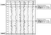
图1是采用本发明方法对某研究区的碳酸盐岩地层进行的地层孔隙流体压力预测。Fig. 1 shows the prediction of formation pore fluid pressure in a carbonate rock formation in a certain study area by using the method of the present invention.
具体实施方式Detailed ways
实施例1Example 1
一种适用于碳酸盐岩地层的地层孔隙流体压力预测方法,基于测井数据计算碳酸盐岩地层的地层孔隙流体压力,步骤包括:A method for predicting formation pore fluid pressure suitable for carbonate rock formations, calculating the formation pore fluid pressure of carbonate rock formations based on well logging data, and the steps include:
步骤1:基于目的层段的实测地层压力数据,获取用于碳酸盐岩地层的地层压力预测的岩石物理参数和指数调节因子的值:Step 1: Based on the measured formation pressure data of the target interval, obtain the values of petrophysical parameters and index adjustment factors for formation pressure prediction of carbonate formations:
步骤1-1:选取研究区的目的层段含有实测压力数据的两口井,记为A井和 B井。A井作为计算井,用于计算多个岩石物理参数及其对应的指数调节因子; B井作为验证井,采用基于A井计算得到多个岩石物理参数及其对应的指数调节因子预测地层压力值,优选地层压力预测值与真实值误差最小的岩石物理参数及其对应的指数调节因子;Step 1-1: Select two wells with measured pressure data in the target interval of the study area, denoted as Well A and Well B. Well A is used as a calculation well to calculate multiple petrophysical parameters and their corresponding exponential adjustment factors; Well B is used as a verification well, and multiple petrophysical parameters and their corresponding exponential adjustment factors calculated based on Well A are used to predict formation pressure values , the petrophysical parameters with the smallest error between the predicted value of formation pressure and the actual value and the corresponding exponential adjustment factor are selected;
步骤1-2:输入A井的测井数据:纵波速度、横波速度、密度,目的层段顶界面深度、目的层段以上的地层平均密度、地层压力实测点的深度和压力值、目的层段顶界面到实测点的采样点个数N、目的层段采样点总个数M;Step 1-2: Input the logging data of Well A: P-wave velocity, shear-wave velocity, density, depth of the top interface of the target interval, average density of the formation above the target interval, depth and pressure value of the formation pressure measurement point, target interval The number N of sampling points from the top interface to the actual measurement point, and the total number of sampling points in the target interval, M;
步骤1-3:计算A井的地层压力实测点的上覆地层压力值和静水压力值,Step 1-3: Calculate the overlying formation pressure value and the hydrostatic pressure value of the formation pressure measurement point of Well A,

Pw_r_A=0.0098×Hr_A (19)Pw_r_A = 0.0098×Hr_A (19)
式中,N是A井目的层段顶界面至地层压力实测点的采样点总数;Pov_r_A是的A 井地层压力实测点的上覆地层压力值,单位MPa;DEN0_A是A井的目的层段以上的地层平均密度,单位g/cm3;H0_A是A井的目的层段顶界面深度,单位m; HA_i是A井的目的层段测井采样点,单位m;DENA_i是对应采样点HA_i的密度值,单位g/cm3;Pw_r_A是A井地层压力实测点的静水压力值,单位MPa;Hr_A是A 井地层压力实测点的深度,单位m;In the formula, N is the total number of sampling points from the top interface of the target interval of Well A to the actual measurement point of formation pressure; Pov_r_A is the overlying formation pressure value of the actual measurement point of formation pressure in Well A, in MPa; DEN0_A is the target layer of Well A The average density of the formation above the interval, unit g/cm3 ; H0_A is the depth of the top interface of the target interval of Well A, unit m; HA_i is the logging sampling point of the target interval of Well A, unit m; DENA_i is the corresponding Density value of sampling point HA_i , unit g/cm3 ; Pw_r_A is the hydrostatic pressure value of formation pressure measurement point of Well A, unit MPa; Hr_A is the depth of formation pressure measurement point of Well A, unit m;
步骤1-4:计算A井地层压力实测点的多个岩石物理参数,如泊松比、杨氏模量、体积模量等,下面仅列举上述3个参数的计算公式,Step 1-4: Calculate multiple petrophysical parameters of the measured formation pressure in Well A, such as Poisson's ratio, Young's modulus, bulk modulus, etc. The following only lists the calculation formulas of the above three parameters.


式中,μr_A是A井地层压力实测点的泊松比;Er_A是A井地层压力实测点的杨氏模量;Kr_A是A井地层压力实测点的体积模量;μr_A是A井地层压力实测点的泊松比;VP_r_A是A井地层压力实测点的纵波速度,单位m/s;VS_r_A是A井地层压力实测点的横波速度,单位m/s;DENr_A是A井地层压力实测点的密度,单位 g/cm3;In the formula, μr_A is the Poisson’s ratio of the formation pressure measurement point of Well A; Er_A is the Young’s modulus of the formation pressure measurement point of Well A; Kr_A is the bulk modulus of the formation pressure measurement point of Well A; μr_A is A Poisson’s ratio of the actual measurement point of formation pressure in well A; VP_r_A is the compression wave velocity of the formation pressure measurement point of Well A, unit m/s; VS_r_A is the shear wave velocity of the formation pressure measurement point of Well A, unit m/s; DENr_A is A The density of the well formation pressure measured point, in g/cm3 ;
步骤1-5:计算A井目的层段的多个岩石物理参数,如泊松比、杨氏模量、体积模量等,并选取目的层段内的最大值,下面仅列举上述3个参数的计算公式,Step 1-5: Calculate multiple petrophysical parameters of the target interval of Well A, such as Poisson's ratio, Young's modulus, bulk modulus, etc., and select the maximum value in the target interval. Only the above three parameters are listed below. the calculation formula,


μmax_A=max(μA_i),i∈[0,M] (26)μmax_A =max(μA_i ),i∈[0,M] (26)
Emax_A=max(EA_i),i∈[0,M] (27)Emax_A =max(EA_i ),i∈[0,M] (27)
Kmax_A=max(KA_i),i∈[0,M] (28)Kmax_A =max(KA_i ),i∈[0,M] (28)
式中,μA_i、EA_i和KA_i代表A井目的层段采样点i对应的泊松比、杨氏模量和体积模量;μmax_A、Emax_A和Kmax_A代表A井目的层段中的最大泊松比、最大样式模量、最大体积模量;M代表A井目的层段的测井采样点总数;VP_A_i代表A井目的层段采样点i对应的纵波速度,单位m/s;VS_A_i代表A井目的层段采样点i对应的横波速度,单位m/s;DENA_i代表A井目的层段采样点i对应的密度,单位 g/cm3;In the formula, μA_i , EA_i and KA_i represent the Poisson’s ratio, Young’s modulus and bulk modulus corresponding to the sampling point i in the target interval of Well A; μmax_A , Emax_A and Kmax_A represent the The maximumPoisson ’s ratio, the maximum pattern modulus, and the maximum bulk modulus of the ; VS_A_i represents the shear wave velocity corresponding to the sampling point i in the target interval of Well A, in m/s; DENA_i represents the density corresponding to the sampling point i in the target interval in Well A, in g/cm3 ;
步骤1-6:计算各个岩石物理参数对应的指数调节因子,下面仅列举上述3 个参数的指数调节因子,Steps 1-6: Calculate the exponential adjustment factors corresponding to each petrophysical parameter. The following only lists the exponential adjustment factors of the above three parameters.


式中,Cμ代表和泊松比相对应的指数调节因子;CE代表和泊松比相对应的指数调节因子;CK代表和泊松比相对应的指数调节因子;Pf_r_A代表A井地层压力实测值,单位Mpa;In the formula, Cμ represents the exponential adjustment factor corresponding to Poisson’s ratio; CE represents the exponential adjustment factor corresponding to Poisson’s ratio; CK represents the exponential adjustment factor corresponding to Poisson’s ratio; Pf_r_A represents the measured formation pressure in Well A value, in Mpa;
步骤1-7:输入验证井B的测井数据:纵波速度、横波速度、密度,目的层段顶界面深度、目的层段以上的地层平均密度、地层压力实测点的深度和压力值、目的层段采样点个数k;Step 1-7: Input the logging data of the verification well B: P-wave velocity, shear wave velocity, density, depth of the top interface of the target interval, average density of the formation above the target interval, depth and pressure value of the formation pressure measurement point, target layer The number of sampling points in the segment k;
步骤1-8:计算B井目的层段每个采样点的上覆地层压力值和静水压力,Steps 1-8: Calculate the overburden pressure value and hydrostatic pressure of each sampling point in the target interval of Well B,

Pw_B_i=0.0098×HB_i (33)Pw_B_i =0.0098×HB_i (33)
式中,k是B井目的层段的实测采样点总数;Pov_B_i是B井对应采样点i的上覆地层压力值,单位MPa;DEN0_B是B井的目的层段以上的地层平均密度,单位 g/cm3;H0_B是B井的目的层段顶界面深度,单位m;HB_i是B井的目的层段测井采样点,单位m;DENB_i是对应采样点i的密度值,单位g/cm3;Pw_B_i是B井对应采样点i的静水压力值,单位MPa;In the formula, k is the total number of measured sampling points in the target interval of Well B; Pov_B_i is the pressure value of the overlying formation corresponding to the sampling point i in Well B, in MPa; DEN0_B is the average density of the formation above the target interval of Well B, Unit g/cm3 ; H0_B is the depth of the top interface of the target interval of Well B, unit m; HB_i is the logging sampling point of the target interval of Well B, unit m; DENB_i is the density value of the corresponding sampling point i, The unit is g/cm3 ; Pw_B_i is the hydrostatic pressure value of Well B corresponding to the sampling point i, in MPa;
步骤1-8:计算B井目的层段的多个岩石物理参数,如泊松比、杨氏模量、体积模量等,并选取目的层段内的最大值,下面仅列举上述3个参数的计算公式,Steps 1-8: Calculate multiple petrophysical parameters of the target interval in Well B, such as Poisson's ratio, Young's modulus, bulk modulus, etc., and select the maximum value in the target interval. Only the above 3 parameters are listed below. the calculation formula,


μmax_B=max(μB_i),i∈[0,k] (37)μmax_B =max(μB_i ),i∈[0,k] (37)
Emax_B=max(EB_i),i∈[0,k] (38)Emax_B =max(EB_i ),i∈[0,k] (38)
Kmax_B=max(KB_i),i∈[0,k] (39)Kmax_B =max(KB_i ),i∈[0,k] (39)
式中,μB_i、EB_i和KB_i代表B井目的层段采样点i对应的泊松比、杨氏模量和体积模量;μmax_B、Emax_B和Kmax_B代表B井目的层段中的最大泊松比、最大样式模量、最大体积模量;VP_B_i代表B井目的层段采样点i对应的纵波速度,单位 m/s;VS_B_i代表B井目的层段采样点i对应的横波速度,单位m/s;DENB_i代表 B井目的层段采样点i对应的密度,单位g/cm3;In the formula, μB_i , EB_i and KB_i represent the Poisson’s ratio, Young’s modulus and bulk modulus corresponding to the sampling point i of the target interval in Well B; μmax_B , Emax_B and Kmax_B represent the target interval in Well B The maximumPoisson ’s ratio, the maximum pattern modulus, and the maximumbulk modulus of Shear wave velocity, in m/s; DENB_i represents the density corresponding to sampling point i in the target interval of Well B, in g/cm3 ;
步骤1-9:计算B井目的层段多个岩石物理参数的地层孔隙压力,下面仅列举上述3个参数的计算公式,Step 1-9: Calculate the formation pore pressure of multiple petrophysical parameters in the target interval of Well B. Only the calculation formulas of the above three parameters are listed below.


式中,Pf_μ_i、Pf_E_i、Pf_K_i分别表示使用B井泊松比、杨氏模量、体积模量计算出的对应采样点i的地层孔隙流体压力,单位MPa;Cμ、CE、CK分别是步骤1-6 中使用A井资料计算出对应泊松比、杨氏模量、体积模量的指数调节因子;In the formula, Pf_μ_i , Pf_E_i , and Pf_K_i represent the formation pore fluid pressure at the corresponding sampling point i calculated using Poisson’s ratio, Young’s modulus, and bulk modulus of Well B, respectively, in MPa; Cμ ,CE ,CK are the exponential adjustment factors corresponding to Poisson's ratio, Young's modulus and bulk modulus calculated using the data of Well A in steps 1-6 respectively;
步骤1-10:计算上述3种岩石物理参数的地层压力和B井实测压力的误差,优选误差最小的参数和对应指数调节因子应用于整个研究区,Step 1-10: Calculate the errors of the formation pressure of the above three petrophysical parameters and the measured pressure of Well B, and apply the parameter with the smallest error and the corresponding exponential adjustment factor to the entire study area.
a=(Pf_μ_r-Pf_B_r)/Pf_B_r (43)a=(Pf_μ_r -Pf_B_r )/Pf_B_r (43)
b=(Pf_E_r-Pf_B_r)/Pf_B_r (44)b=(Pf_E_r -Pf_B_r )/Pf_B_r (44)
c=(Pf_K_r-Pf_B_r)/Pf_B_r (45)c=(Pf_K_r -Pf_B_r )/Pf_B_r (45)
式中,a、b、c分别代表泊松比、杨氏模量、体积模量计算的地层孔隙流体压力的误差;Pf_B_r是B井实测点深度为HB_r处的地层孔隙流体压力,单位MPa; Pf_μ_r、Pf_E_r、Pf_K_r分别代表实测点深度为HB_r处验算的地层孔隙流体压力,单位MPa;In the formula, a, b, and c represent theerrors ofPoisson ’s ratio, Young’s modulus, and bulk modulus, respectively; MPa; Pf_μ_r , Pf_E_r , and Pf_K_r respectively represent the formation pore fluid pressure checked at the depth of the measured point HB_r , in MPa;
步骤2:计算研究区未知井的地层孔隙流体压力,以步骤1的优选结果为体积模量为例:Step 2: Calculate the formation pore fluid pressure of the unknown well in the study area, taking the optimal result of Step 1 as the bulk modulus as an example:
步骤2-1:输入未知井的测井数据:纵波速度、横波速度、密度,目的层段顶界面深度、目的层段以上的地层平均密度、目的层段的测井采样点个数l;Step 2-1: Input the logging data of the unknown well: longitudinal wave velocity, shear wave velocity, density, depth of the top interface of the target interval, average density of the formation above the target interval, and the number of logging sampling points in the target interval l;
步骤2-2:计算未知井目的层段每个采样点的上覆地层压力值和静水压力,Step 2-2: Calculate the overburden pressure value and hydrostatic pressure of each sampling point in the target interval of the unknown well,

Pw_i=0.0098×Hi (47)Pw_i =0.0098×Hi (47)
式中,l未知井井目的层段的实测采样点总数;Pov_i是未知井对应采样点i的上覆地层压力值,单位MPa;DEN0是未知井的目的层段以上的地层平均密度,单位g/cm3;H0是未知井的目的层段顶界面深度,单位m;Hi是未知井的目的层段测井采样点,单位m;DENi是对应采样点i的密度值,单位g/cm3;Pw_i是未知井对应采样点i的静水压力值,单位MPa;In the formula, l is the total number of measured sampling points in the target interval of the unknown well; Pov_i is the pressure value of the overlying formation corresponding to the sampling point i of the unknown well, in MPa; DEN0 is the average density of the formation above the target interval of the unknown well, Unit g/cm3 ; H0 is the depth of the top interface of the target interval of the unknown well, unit m; Hi is the logging sampling point of the target interval of the unknown well, unit m; DENi is the density value of the corresponding sampling point i, The unit is g/cm3 ; Pw_i is the hydrostatic pressure value of the unknown well corresponding to the sampling point i, in MPa;
步骤2-3:计算未知井目的层段的体积模量,并选取目的层段内的最大值,Step 2-3: Calculate the bulk modulus of the target interval of the unknown well, and select the maximum value in the target interval,

Kmax_B=max(KB_i),i∈[0,k] (49)Kmax_B =max(KB_i ),i∈[0,k] (49)
式中,Ki代表未知井目的层段采样点i对应的体积模量;Kmax代表未知井目的层段中的最大体积模量;VP_i代表未知井目的层段采样点i对应的纵波速度,单位 m/s;VS_i代未知井目的层段采样点i对应的横波速度,单位m/s;DENi代表B井目的层段采样点i对应的密度,单位g/cm3;In the formula, Ki represents the bulk modulus corresponding to the sampling point i of the unknown well target interval; Kmax represents the maximum bulk modulus in the unknown well target interval;VP_i represents the P-wave velocity corresponding to the unknown well target interval sampling point i , unit m/s; VS_i represents the shear wave velocity corresponding to the sampling point i of the target interval of the unknown well, unit m/s; DENi represents the density corresponding to the sampling point i of the target interval of Well B, unit g/cm3 ;
步骤2-4:计算未知井目的层段的地层孔隙流体压力,Step 2-4: Calculate the formation pore fluid pressure in the unknown well target interval,

式中,Pf_i分别表示使用未知井体积模量计算出的对应采样点i的地层孔隙流体压力,单位MPa;CK是步骤1-6中使用A井资料计算出对体积模量的指数调节因子。In the formula, Pf_i respectively represents the formation pore fluid pressure at the corresponding sampling point i calculated using the bulk modulus of the unknown well, in MPa;CK is the exponential adjustment to the bulk modulus calculated in steps 1-6 using the data of Well A factor.
实施例2Example 2
为了直观的展示如何优选工区指数调节因子和岩石物理参数,并且显示此公式在碳酸盐岩地区的高精度和先进性。In order to intuitively show how to optimize the index adjustment factor and petrophysical parameters of the work area, and to show the high precision and advanced nature of this formula in the carbonate rock area.
图1是采用本发明公式与步骤的地层孔隙流体压力预测成果。柱状图第一列为目的层深度,单位m;第二列和第三列分别为纵波速度、横波速度,单位m/s;第四列为密度,单位g/cm3;第五列是采用泊松比计算的地层孔隙流体压力Pf_μ,第六列是采用杨氏模量计算的孔隙流体压力Pf_E,第七列是采用体积模量计算的孔隙流体压力Pf_K,单位MPa:Fig. 1 is the prediction result of formation pore fluid pressure using the formula and steps of the present invention. The first column of the histogram is the depth of the target layer, in m; the second and third columns are the longitudinal wave velocity and shear wave velocity, respectively, in m/s; the fourth column is the density, in g/cm3 ; The formation pore fluid pressure Pf_μ calculated by Poisson’s ratio, the sixth column is the pore fluid pressure Pf_E calculated using Young’s modulus, and the seventh column is the pore fluid pressure Pf_K calculated using the bulk modulus, in MPa:
该目的层段有2个实测点,在第一个实测点使用泊松比、杨氏模量、体积模量计算的误差分别是:1.06%、3.51%、0.69%。在第二个实测点使用泊松比、杨氏模量、体积模量计算的误差分别是:3.44%、2.87%、2.19%。There are two measured points in this target interval, and the errors calculated by Poisson's ratio, Young's modulus and bulk modulus at the first measured point are: 1.06%, 3.51%, and 0.69%, respectively. The errors calculated using Poisson's ratio, Young's modulus, and bulk modulus at the second measured point are: 3.44%, 2.87%, and 2.19%, respectively.
综合考虑:体积模量参与计算的误差最小。因此,研究区的未知井采用体积模量预测地层孔隙流体压力。Comprehensive consideration: the bulk modulus participates in the calculation with the smallest error. Therefore, the bulk modulus is used to predict the formation pore fluid pressure in unknown wells in the study area.
以上所述仅为本发明的较佳实施例而已,并不用以限制本发明,凡在本发明的精神和原则之内所作的任何修改、等同替换和改进等,均应包含在本发明的保护范围之内。The above descriptions are only preferred embodiments of the present invention and are not intended to limit the present invention. Any modifications, equivalent replacements and improvements made within the spirit and principles of the present invention shall be included in the protection of the present invention. within the range.
Claims (1)


Priority Applications (1)
| Application Number | Priority Date | Filing Date | Title |
|---|---|---|---|
| CN202210040987.4ACN114492235B (en) | 2022-01-14 | 2022-01-14 | Stratum pore fluid pressure prediction method suitable for carbonate rock stratum |
Applications Claiming Priority (1)
| Application Number | Priority Date | Filing Date | Title |
|---|---|---|---|
| CN202210040987.4ACN114492235B (en) | 2022-01-14 | 2022-01-14 | Stratum pore fluid pressure prediction method suitable for carbonate rock stratum |
Publications (2)
| Publication Number | Publication Date |
|---|---|
| CN114492235Atrue CN114492235A (en) | 2022-05-13 |
| CN114492235B CN114492235B (en) | 2023-04-07 |
Family
ID=81512450
Family Applications (1)
| Application Number | Title | Priority Date | Filing Date |
|---|---|---|---|
| CN202210040987.4AExpired - Fee RelatedCN114492235B (en) | 2022-01-14 | 2022-01-14 | Stratum pore fluid pressure prediction method suitable for carbonate rock stratum |
Country Status (1)
| Country | Link |
|---|---|
| CN (1) | CN114492235B (en) |
Citations (7)
| Publication number | Priority date | Publication date | Assignee | Title |
|---|---|---|---|---|
| CN104500040A (en)* | 2014-10-16 | 2015-04-08 | 西南石油大学 | Wellbore multi-section fluid movement boundary tracking method in acidification process of horizontal well |
| CN106054248A (en)* | 2016-07-15 | 2016-10-26 | 河海大学 | Earthquake rock physical inversion method based on large area tight reservoir |
| CN107016219A (en)* | 2017-05-09 | 2017-08-04 | 中国石油天然气股份有限公司 | Early warning method and system for carbonate reservoir drilling emptying |
| US20170370197A1 (en)* | 2016-06-23 | 2017-12-28 | Saudi Arabian Oil Company | Hydraulic Fracturing In Kerogen-Rich Unconventional Formations |
| CN108205158A (en)* | 2018-01-26 | 2018-06-26 | 成都理工大学 | A kind of formation pore pressure Forecasting Methodology and system based on index constraint |
| CN109283597A (en)* | 2018-11-15 | 2019-01-29 | 中国地质大学(武汉) | A method for predicting overpressure in carbonate rock formations |
| CN109577969A (en)* | 2018-12-07 | 2019-04-05 | 中国地质大学(武汉) | A method of Pore Pressure on Carbonate Rock Formation is calculated based on rock compressibility |
- 2022
- 2022-01-14CNCN202210040987.4Apatent/CN114492235B/ennot_activeExpired - Fee Related
Patent Citations (7)
| Publication number | Priority date | Publication date | Assignee | Title |
|---|---|---|---|---|
| CN104500040A (en)* | 2014-10-16 | 2015-04-08 | 西南石油大学 | Wellbore multi-section fluid movement boundary tracking method in acidification process of horizontal well |
| US20170370197A1 (en)* | 2016-06-23 | 2017-12-28 | Saudi Arabian Oil Company | Hydraulic Fracturing In Kerogen-Rich Unconventional Formations |
| CN106054248A (en)* | 2016-07-15 | 2016-10-26 | 河海大学 | Earthquake rock physical inversion method based on large area tight reservoir |
| CN107016219A (en)* | 2017-05-09 | 2017-08-04 | 中国石油天然气股份有限公司 | Early warning method and system for carbonate reservoir drilling emptying |
| CN108205158A (en)* | 2018-01-26 | 2018-06-26 | 成都理工大学 | A kind of formation pore pressure Forecasting Methodology and system based on index constraint |
| CN109283597A (en)* | 2018-11-15 | 2019-01-29 | 中国地质大学(武汉) | A method for predicting overpressure in carbonate rock formations |
| CN109577969A (en)* | 2018-12-07 | 2019-04-05 | 中国地质大学(武汉) | A method of Pore Pressure on Carbonate Rock Formation is calculated based on rock compressibility |
Non-Patent Citations (3)
| Title |
|---|
| 熊晓军等: "一种适用于欠压实成因的地层孔隙流体压力预测技术"* |
| 路保平等: "基于流体声速的碳酸盐岩地层孔隙压力求取方法"* |
| 陶磊等: "一种碳酸盐岩气藏地层孔隙压力计算方法"* |
Also Published As
| Publication number | Publication date |
|---|---|
| CN114492235B (en) | 2023-04-07 |
Similar Documents
| Publication | Publication Date | Title |
|---|---|---|
| CN106468172B (en) | A logging interpretation method for low-resistivity reservoirs in ultra-low permeability sandstone reservoirs | |
| Wu et al. | Numerical simulation of mud-filtrate invasion in deviated wells | |
| US8359184B2 (en) | Method, program and computer system for scaling hydrocarbon reservoir model data | |
| CA2890817C (en) | System, method and computer program product for determining placement of perforation intervals using facies, fluid boundaries, geobodies and dynamic fluid properties | |
| CN104912550A (en) | Method for quantitatively calculating reservoir fluid producing profile by nuclear magnetic resonance well logging information | |
| CN106154351A (en) | A kind of evaluation method of low porosity permeability reservoir permeability | |
| US20100185424A1 (en) | Method, Program and Computer System for Conciliating Hydrocarbon Reservoir Model Data | |
| CN107590550A (en) | The method evaluated and predicted about super-low permeability reservoir oil field production capacity | |
| EP3245384A1 (en) | Measuring inter-reservoir cross flow rate between adjacent reservoir layers form transient pressure tests | |
| CN105931125B (en) | Method for predicting yield of compact oil staged multi-cluster volume fracturing horizontal well | |
| CN116047602B (en) | Type II hydrate saturation prediction method based on hydrocarbon production numerical simulation | |
| CN112083515B (en) | Quantitative characterization of excavation effect of tight sandstone low-resistivity reservoir and evaluation method of gas-bearing property | |
| US12352163B2 (en) | Integrated time-lapse gas geochemistry and equation of state modeling for evaluating desorbed gas in production | |
| CN106019378A (en) | Dynamic reconstruction method of time-shift logging curve | |
| Baker et al. | Permeability prediction in carbonate reservoir rock using FZI | |
| Suryanarayana et al. | Dynamic modeling of invasion damage and impact on production in horizontal wells | |
| CN112145165B (en) | Microcrack-pore type reservoir dynamic and static permeability conversion method | |
| Madalimov et al. | Heterogeneity Modeling and Heterogeneity-Based Upscaling for Reservoir Characterization and Simulation | |
| Zughar et al. | Petrophysical Properties of an Iraqi Carbonate Reservoir Using Well Log Evaluation | |
| CN119862501A (en) | Shallow sea gravity flow water channel reservoir porosity prediction method | |
| CN112381259B (en) | Dynamic prediction calculation method for productivity of tight conglomerate reservoir | |
| Aslanyan et al. | Assessing macroscopic dynamic permeability through pressure and noise analysis | |
| CN114492235B (en) | Stratum pore fluid pressure prediction method suitable for carbonate rock stratum | |
| Worthington et al. | Optimizing the value of reservoir simulation through quality-assured initialization | |
| Ballin et al. | New reservoir dynamic connectivity measurement for efficient well placement strategy analysis under depletion |
Legal Events
| Date | Code | Title | Description |
|---|---|---|---|
| PB01 | Publication | ||
| PB01 | Publication | ||
| SE01 | Entry into force of request for substantive examination | ||
| SE01 | Entry into force of request for substantive examination | ||
| GR01 | Patent grant | ||
| GR01 | Patent grant | ||
| CF01 | Termination of patent right due to non-payment of annual fee | Granted publication date:20230407 | |
| CF01 | Termination of patent right due to non-payment of annual fee |