CN114469243A - Tibial osteotomy system and its osteotomy volume adjustment device - Google Patents
Tibial osteotomy system and its osteotomy volume adjustment deviceDownload PDFInfo
- Publication number
- CN114469243A CN114469243ACN202011252828.8ACN202011252828ACN114469243ACN 114469243 ACN114469243 ACN 114469243ACN 202011252828 ACN202011252828 ACN 202011252828ACN 114469243 ACN114469243 ACN 114469243A
- Authority
- CN
- China
- Prior art keywords
- rod
- shaft
- osteotomy
- guide groove
- piece
- Prior art date
- Legal status (The legal status is an assumption and is not a legal conclusion. Google has not performed a legal analysis and makes no representation as to the accuracy of the status listed.)
- Granted
Links
Images


Classifications
- A—HUMAN NECESSITIES
- A61—MEDICAL OR VETERINARY SCIENCE; HYGIENE
- A61B—DIAGNOSIS; SURGERY; IDENTIFICATION
- A61B17/00—Surgical instruments, devices or methods
- A61B17/16—Instruments for performing osteoclasis; Drills or chisels for bones; Trepans
- A61B17/1657—Bone breaking devices
- A—HUMAN NECESSITIES
- A61—MEDICAL OR VETERINARY SCIENCE; HYGIENE
- A61B—DIAGNOSIS; SURGERY; IDENTIFICATION
- A61B17/00—Surgical instruments, devices or methods
- A61B17/16—Instruments for performing osteoclasis; Drills or chisels for bones; Trepans
- A61B17/1662—Instruments for performing osteoclasis; Drills or chisels for bones; Trepans for particular parts of the body
- A—HUMAN NECESSITIES
- A61—MEDICAL OR VETERINARY SCIENCE; HYGIENE
- A61B—DIAGNOSIS; SURGERY; IDENTIFICATION
- A61B17/00—Surgical instruments, devices or methods
- A61B17/16—Instruments for performing osteoclasis; Drills or chisels for bones; Trepans
- A61B17/17—Guides or aligning means for drills, mills, pins or wires
- A61B17/1732—Guides or aligning means for drills, mills, pins or wires for bone breaking devices
- A—HUMAN NECESSITIES
- A61—MEDICAL OR VETERINARY SCIENCE; HYGIENE
- A61B—DIAGNOSIS; SURGERY; IDENTIFICATION
- A61B17/00—Surgical instruments, devices or methods
- A61B17/16—Instruments for performing osteoclasis; Drills or chisels for bones; Trepans
- A61B17/17—Guides or aligning means for drills, mills, pins or wires
- A61B17/1739—Guides or aligning means for drills, mills, pins or wires specially adapted for particular parts of the body
- A—HUMAN NECESSITIES
- A61—MEDICAL OR VETERINARY SCIENCE; HYGIENE
- A61B—DIAGNOSIS; SURGERY; IDENTIFICATION
- A61B90/00—Instruments, implements or accessories specially adapted for surgery or diagnosis and not covered by any of the groups A61B1/00 - A61B50/00, e.g. for luxation treatment or for protecting wound edges
- A61B90/08—Accessories or related features not otherwise provided for
Landscapes
- Health & Medical Sciences (AREA)
- Surgery (AREA)
- Life Sciences & Earth Sciences (AREA)
- Heart & Thoracic Surgery (AREA)
- Molecular Biology (AREA)
- Oral & Maxillofacial Surgery (AREA)
- Engineering & Computer Science (AREA)
- Biomedical Technology (AREA)
- Nuclear Medicine, Radiotherapy & Molecular Imaging (AREA)
- Medical Informatics (AREA)
- Orthopedic Medicine & Surgery (AREA)
- Animal Behavior & Ethology (AREA)
- General Health & Medical Sciences (AREA)
- Public Health (AREA)
- Veterinary Medicine (AREA)
- Dentistry (AREA)
- Pathology (AREA)
- Surgical Instruments (AREA)
Abstract
Translated fromChinese
Description
Translated fromChinese技术领域technical field
本发明涉及医疗器械技术领域,特别是涉及一种胫骨截骨系统及其截骨量调整装置。The invention relates to the technical field of medical devices, in particular to a tibial osteotomy system and a device for adjusting the osteotomy amount.
背景技术Background technique
单髁膝关节置换手术过程中需要对胫骨侧进行截骨,以便安装合适的胫骨假体。截骨位置的准确性将直接影响到假体安装的结果,基于此,在膝关节置换手术中,通常采取胫骨截骨量微调装置对胫骨截骨板高度进行微调,使胫骨截骨板到达最合适的截骨位置,以便对胫骨平台的精确截骨。Unicondylar knee arthroplasty requires an osteotomy on the tibial side in order to install a suitable tibial component. The accuracy of the osteotomy position will directly affect the result of the prosthesis installation. Based on this, in knee replacement surgery, the tibial osteotomy volume fine-tuning device is usually used to fine-tune the height of the tibial osteotomy plate, so that the tibial osteotomy plate can reach the highest level. Proper osteotomy location for precise osteotomy of the tibial plateau.
传统的胫骨截骨量微调装置一般为螺纹微调式或卡扣式(即齿轮式)。The traditional tibial osteotomy volume fine-tuning device is generally a thread fine-tuning type or a snap-on type (ie, a gear type).
其中,螺纹微调式是将上端杆和下端杆通过螺纹连接一起,胫骨截骨板与上端杆相连接,通过旋转螺母使上端杆相对下端杆上下移动,进而实现胫骨截骨板的微调。这种结构,在螺纹旋转过程中,容易产生磨屑而引起卡顿,或因螺纹精度问题而容易发生卡顿,而且旋转力易导致上端杆偏移,另外锁合不稳定,易松脱。Among them, the thread fine-tuning type is that the upper end rod and the lower end rod are connected together by thread, the tibial osteotomy plate is connected with the upper end rod, and the upper end rod is moved up and down relative to the lower end rod by rotating the nut, thereby realizing the fine adjustment of the tibial osteotomy plate. In this structure, during the thread rotation process, it is easy to generate wear debris and cause jamming, or it is easy to cause jamming due to the problem of thread accuracy, and the rotation force is easy to cause the upper end rod to shift, and the locking is unstable and easy to loosen.
卡扣式微调方式大多是通过控制齿条之间的啮合或松脱来控制上端杆的锁合或移动,在齿条彼此之间处于松脱时,可以移动上端杆以调整连接于上端杆的胫骨截骨板的位置,在齿条彼此之间处于啮合时,齿条锁住上端杆的位置,以固定胫骨截骨板的位置。这种结构虽然锁合稳定可靠,但调节连续性差,无法满足对胫骨截骨板的位置的精准调节。Most of the snap-on fine-tuning methods control the locking or movement of the upper end rod by controlling the meshing or loosening between the racks. When the racks are loose from each other, the upper end rod can be moved to adjust the The position of the tibial osteotomy plate, when the racks are engaged with each other, the rack locks the position of the upper end rod to fix the position of the tibial osteotomy plate. Although this structure has stable and reliable locking, it has poor adjustment continuity and cannot meet the precise adjustment of the position of the tibial osteotomy plate.
发明内容SUMMARY OF THE INVENTION
基于此,本发明提供一种调节效果较为精确的截骨量调整装置以及包括该截骨量调整装置。Based on this, the present invention provides an osteotomy volume adjustment device with a relatively accurate adjustment effect, and an osteotomy volume adjustment device including the same.
本发明提供的一种截骨量调整装置,包括:An osteotomy volume adjustment device provided by the present invention includes:
第一杆件,开设有第一导槽,所述第一导槽大致沿所述第一杆件的长度方向延伸;The first rod is provided with a first guide groove, and the first guide groove extends substantially along the length direction of the first rod;
第二杆件,与所述第一杆件相连,所述第二杆件上连接有第一轴,所述第一轴插设于所述第一导槽,且能够沿所述第一导槽移动;The second rod is connected to the first rod, the second rod is connected with a first shaft, the first shaft is inserted in the first guide groove, and can move along the first guide slot movement;
调节件,所述调节件通过所述第一轴与所述第二杆件转动连接,所述调节件上开设有第二导槽,所述第一杆件设有第二轴,所述第二轴插设于所述第二导槽,当所述调节件绕所述第一轴相对所述第一杆件转动时,所述第二轴沿所述第二导槽移动并靠近或远离所述第一轴,以调整所述第一杆件与所述第二杆件在沿所述第一杆件的长度方向上的相对位置。an adjusting member, the adjusting member is rotatably connected with the second rod member through the first shaft, a second guide groove is formed on the adjusting member, the first rod member is provided with a second shaft, and the first rod member is provided with a second shaft. Two shafts are inserted into the second guide groove. When the adjusting member rotates relative to the first rod member around the first shaft, the second shaft moves along the second guide groove and approaches or moves away from it. The first shaft is used to adjust the relative position of the first rod and the second rod along the length direction of the first rod.
在其中一个实施例中,所述第一杆件开设有插接腔,所述第一导槽贯穿所述插接腔的侧壁,以与所述插接腔相连通,所述第二杆件可伸缩移动地插设于所述插接腔。In one embodiment, the first rod is provided with a plug cavity, the first guide groove penetrates through the side wall of the plug cavity to communicate with the plug cavity, and the second rod is retractable It is movably inserted into the insertion cavity.
在其中一个实施例中,包括止动件,所述止动件能够沿所述第二杆件的长度方向移动至与所述调节件相抵持,以限制所述调节件绕所述第一轴转动,且所述止动件能够沿所述第二杆件的长度方向离开所述调节件,以解除对所述调节件的抵持限位。In one of the embodiments, a stopper is included, and the stopper can move along the length direction of the second rod to abut against the adjustment member, so as to restrict the adjustment member from moving around the first axis rotate, and the stop piece can be separated from the adjusting piece along the length direction of the second rod, so as to release the abutting limit of the adjusting piece.
在其中一个实施例中,所述调节件设有齿状边缘,所述止动件具有锁止齿,所述锁止齿与所述齿状边缘相配合。In one of the embodiments, the adjusting member is provided with a toothed edge, and the stop member has a locking tooth, and the locking tooth is matched with the toothed edge.
在其中一个实施例中,所述齿状边缘的啮合齿沿所述第一轴的周向呈圆弧形排布。In one embodiment, the meshing teeth of the toothed edge are arranged in a circular arc shape along the circumferential direction of the first shaft.
在其中一个实施例中,所述齿状边缘的齿顶半径为15mm~60mm。In one of the embodiments, the tooth tip radius of the toothed edge is 15mm˜60mm.
在其中一个实施例中,包括弹性件,所述弹性件设于所述第一杆件与所述止动件之间,或设于所述第二杆件与所述止动件之间。In one embodiment, an elastic member is included, and the elastic member is provided between the first rod and the stopper, or between the second rod and the stopper.
在其中一个实施例中,所述弹性件为弹簧,所述弹簧套设于所述第一杆件或所述第二杆件,并将所述止动件弹性地抵持于所述调节件。In one embodiment, the elastic member is a spring, the spring is sleeved on the first rod member or the second rod member, and elastically presses the stop member against the adjustment member .
在其中一个实施例中,所述第一杆件或所述第二杆件设有抵持面,所述弹簧与所述抵持面相抵接。In one embodiment, the first rod member or the second rod member is provided with a bearing surface, and the spring abuts against the bearing surface.
在其中一个实施例中,以所述第一轴与所述调节件的交点为圆心,所述第二导槽在各弧度上的半径不同。In one of the embodiments, with the intersection of the first axis and the adjusting member as the center of the circle, the radius of the second guide groove on each radian is different.
另一方面,本发明提供一种胫骨截骨系统,包括截骨导板、抱踝器及上述的截骨量调整装置,所述截骨导板具有截骨槽,所述截骨槽贯穿所述截骨导板的相对两侧,所述抱踝器用于固定于患者的下肢,所述第一杆件和所述第二杆件中的一者与所述截骨导板连接,另一者与所述抱踝器连接。In another aspect, the present invention provides a tibial osteotomy system, comprising an osteotomy guide plate, an ankle holder and the above-mentioned osteotomy volume adjustment device, wherein the osteotomy guide plate has an osteotomy groove, and the osteotomy groove penetrates the osteotomy. On opposite sides of the bone guide plate, the ankle brace is used to fix the lower limbs of the patient, one of the first rod and the second rod is connected with the osteotomy guide, and the other is connected with the Ankle hugger connection.
本发明提供的胫骨截骨系统及其截骨量调整装置,该截骨量调整装置包括第一杆件、第二杆件和调节件,第一杆件开设有第一导槽,第二杆件上连接有第一轴,第一轴插设于第一导槽,调节件通过第一轴与第二杆件转动连接,调节件上开设有第二导槽,第一杆件设有第二轴,当调节件绕第一轴相对第一杆件转动时,第二轴沿第二导槽移动并靠近或远离第一轴,以调整第一杆件与第二杆件在沿第一杆件的长度方向上的相对位置。由于第二轴沿第二导槽移动时能够连续性精细地相对第一轴移动,从而该截骨量调整装置在调整截骨位置时,能够获得连续的精确微调效果。The present invention provides a tibial osteotomy system and a device for adjusting the amount of osteotomy. The device for adjusting the amount of osteotomy includes a first rod, a second rod and an adjusting member. The first rod is provided with a first guide groove, and the second rod is provided with a first guide groove. A first shaft is connected to the piece, the first shaft is inserted into the first guide groove, the adjusting piece is rotatably connected with the second rod through the first shaft, the adjusting piece is provided with a second guide groove, and the first rod is provided with a second rod. Two shafts, when the adjusting member rotates relative to the first rod around the first shaft, the second shaft moves along the second guide groove and moves closer to or away from the first shaft, so as to adjust the first rod and the second rod along the first shaft. The relative position along the length of the rod. Since the second shaft can move continuously and finely relative to the first shaft when moving along the second guide groove, the osteotomy amount adjusting device can obtain a continuous and precise fine-tuning effect when adjusting the osteotomy position.
附图说明Description of drawings
为了更清楚地说明本发明实施例或现有技术中的技术方案,下面将对实施例或现有技术描述中所需要使用的附图作简单地介绍,显而易见地,下面描述中的附图仅仅是本发明的一些实施例,对于本领域普通技术人员来讲,在不付出创造性劳动的前提下,还可以根据这些附图获得其他实施例的附图。In order to explain the embodiments of the present invention or the technical solutions in the prior art more clearly, the following briefly introduces the accompanying drawings that need to be used in the description of the embodiments or the prior art. Obviously, the accompanying drawings in the following description are only These are some embodiments of the present invention. For those of ordinary skill in the art, the drawings of other embodiments can also be obtained according to these drawings without creative efforts.
图1为一实施例的胫骨截骨系统的截骨量调整装置的结构示意图;1 is a schematic structural diagram of an osteotomy volume adjusting device of a tibial osteotomy system according to an embodiment;
图2为一实施例的胫骨截骨系统安装于胫骨时,第一杆件和第二杆件分别与截骨导板和抱踝器的连接结构示意图;2 is a schematic diagram of the connection structure of the first rod and the second rod respectively with the osteotomy guide and the ankle support when the tibial osteotomy system of an embodiment is installed on the tibia;
图3为一实施例的胫骨截骨系统,第一杆件和第二杆件分别与截骨导板和抱踝器的连接时立体结构示意图;Fig. 3 is a tibial osteotomy system according to an embodiment, a three-dimensional schematic diagram of a first rod and a second rod respectively connected to the osteotomy guide and the ankle holder;
图4为图3示出的胫骨截骨系统中的截骨导板的截面结构示意图;4 is a schematic cross-sectional structural diagram of an osteotomy guide plate in the tibial osteotomy system shown in FIG. 3;
图5为图1示出的截骨量调整装置的第一杆件的局部结构示意图;Fig. 5 is a partial structural schematic diagram of the first rod of the osteotomy amount adjustment device shown in Fig. 1;
图6为图1示出的截骨量调整装置的第二杆件的局部结构示意图;Fig. 6 is a partial structural schematic diagram of the second rod of the osteotomy amount adjustment device shown in Fig. 1;
图7为图1示出的截骨量调整装置的调节件的结构示意图;FIG. 7 is a schematic structural diagram of an adjusting member of the osteotomy volume adjusting device shown in FIG. 1;
图8为一实施例的截骨量调整装置的调节件的俯视结构示意图;8 is a schematic top view of the structure of an adjusting member of an osteotomy volume adjusting device according to an embodiment;
图9为一实施例的截骨量调整装置的止动件的立体结构示意图。FIG. 9 is a schematic three-dimensional structural diagram of a stopper of an osteotomy volume adjusting device according to an embodiment.
具体实施方式Detailed ways
为使本发明的上述目的、特征和优点能够更加明显易懂,下面结合附图对本发明的具体实施方式做详细的说明。在下面的描述中阐述了很多具体细节以便于充分理解本发明。但是本发明能够以很多不同于在此描述的其它方式来实施,本领域技术人员可以在不违背本发明内涵的情况下做类似改进,因此本发明不受下面公开的具体实施例的限制。In order to make the above objects, features and advantages of the present invention more clearly understood, the specific embodiments of the present invention will be described in detail below with reference to the accompanying drawings. In the following description, numerous specific details are set forth in order to provide a thorough understanding of the present invention. However, the present invention can be implemented in many other ways different from those described herein, and those skilled in the art can make similar improvements without departing from the connotation of the present invention. Therefore, the present invention is not limited by the specific embodiments disclosed below.
在本发明的描述中,需要理解的是,术语“中心”、“纵向”、“横向”、“长度”、“宽度”、“厚度”、“上”、“下”、“前”、“后”、“左”、“右”、“竖直”、“水平”、“顶”、“底”、“内”、“外”、“顺时针”、“逆时针”、“轴向”、“径向”、“周向”等指示的方位或位置关系为基于附图所示的方位或位置关系,仅是为了便于描述本发明和简化描述,而不是指示或暗示所指的装置或元件必须具有特定的方位、以特定的方位构造和操作,因此不能理解为对本发明的限制。In the description of the present invention, it should be understood that the terms "center", "longitudinal", "lateral", "length", "width", "thickness", "upper", "lower", "front", " Back, Left, Right, Vertical, Horizontal, Top, Bottom, Inner, Outer, Clockwise, Counterclockwise, Axial , "radial", "circumferential" and other indicated orientations or positional relationships are based on the orientations or positional relationships shown in the accompanying drawings, and are only for the convenience of describing the present invention and simplifying the description, rather than indicating or implying the indicated device or Elements must have a particular orientation, be constructed and operate in a particular orientation and are therefore not to be construed as limitations of the invention.
此外,术语“第一”、“第二”仅用于描述目的,而不能理解为指示或暗示相对重要性或者隐含指明所指示的技术特征的数量。由此,限定有“第一”、“第二”的特征可以明示或者隐含地包括至少一个该特征。在本发明的描述中,“多个”的含义是至少两个,例如两个,三个等,除非另有明确具体的限定。In addition, the terms "first" and "second" are only used for descriptive purposes, and should not be construed as indicating or implying relative importance or implying the number of indicated technical features. Thus, a feature delimited with "first", "second" may expressly or implicitly include at least one of that feature. In the description of the present invention, "plurality" means at least two, such as two, three, etc., unless otherwise expressly and specifically defined.
在本发明中,除非另有明确的规定和限定,术语“安装”、“相连”、“连接”、“固定”等术语应做广义理解,例如,可以是固定连接,也可以是可拆卸连接,或成一体;可以是机械连接,也可以是电连接;可以是直接相连,也可以通过中间媒介间接相连,可以是两个元件内部的连通或两个元件的相互作用关系,除非另有明确的限定。对于本领域的普通技术人员而言,可以根据具体情况理解上述术语在本发明中的具体含义。In the present invention, unless otherwise expressly specified and limited, the terms "installed", "connected", "connected", "fixed" and other terms should be understood in a broad sense, for example, it may be a fixed connection or a detachable connection , or integrated; it can be a mechanical connection or an electrical connection; it can be directly connected or indirectly connected through an intermediate medium, it can be the internal connection of two elements or the interaction relationship between the two elements, unless otherwise specified limit. For those of ordinary skill in the art, the specific meanings of the above terms in the present invention can be understood according to specific situations.
在本发明中,除非另有明确的规定和限定,第一特征在第二特征“上”或“下”可以是第一和第二特征直接接触,或第一和第二特征通过中间媒介间接接触。而且,第一特征在第二特征“之上”、“上方”和“上面”可是第一特征在第二特征正上方或斜上方,或仅仅表示第一特征水平高度高于第二特征。第一特征在第二特征“之下”、“下方”和“下面”可以是第一特征在第二特征正下方或斜下方,或仅仅表示第一特征水平高度小于第二特征。In the present invention, unless otherwise expressly specified and limited, a first feature "on" or "under" a second feature may be in direct contact between the first and second features, or the first and second features indirectly through an intermediary touch. Also, the first feature being "above", "over" and "above" the second feature may mean that the first feature is directly above or obliquely above the second feature, or simply means that the first feature is level higher than the second feature. The first feature being "below", "below" and "below" the second feature may mean that the first feature is directly below or obliquely below the second feature, or simply means that the first feature has a lower level than the second feature.
需要说明的是,当元件被称为“固定于”或“设置于”另一个元件,它可以直接在另一个元件上或者也可以存在居中的元件。当一个元件被认为是“连接”另一个元件,它可以是直接连接到另一个元件或者可能同时存在居中元件。本文所使用的术语“垂直的”、“水平的”、“上”、“下”、“左”、“右”以及类似的表述只是为了说明的目的,并不表示是唯一的实施方式。It should be noted that when an element is referred to as being "fixed to" or "disposed on" another element, it can be directly on the other element or an intervening element may also be present. When an element is referred to as being "connected" to another element, it can be directly connected to the other element or intervening elements may also be present. The terms "vertical", "horizontal", "upper", "lower", "left", "right" and similar expressions used herein are for the purpose of illustration only and do not represent the only embodiment.
结合图1所示,本发明提供的一种截骨量调整装置10,用于安装在胫骨截骨系统中,调整截骨的位置,从而满足对胫骨B平台精确截骨需要。Referring to Fig. 1, the present invention provides an osteotomy
在一实施例中,截骨量调整装置10包括第一杆件1和第二杆件2。通过调整第一杆件1和第二杆件2的相对位置,改变第一杆件1和第二杆件2的整体长度,从而适应截骨高度的需要。In one embodiment, the osteotomy
例如,结合图2和图3所示,在本发明提供一种胫骨截骨系统中,截骨量调整装置10的第一杆件1和第二杆件2分别连接截骨导板20和抱踝器30。在使用胫骨截骨系统时,抱踝器30夹持固定在患者下肢(胫骨B)的靠近踝关节B2位置处,从而在截骨量调整装置10调整第一杆件1和第二杆件2的相对位置后,使得截骨导板20相对抱踝器30升降移动,由于抱踝器30被固定在胫骨B上,从而通过截骨量调整装置10调整截骨导板20的位置时,截骨导板20能够相对胫骨B移动,最终使得截骨导板20处于邻近胫骨B的关节面B1下方比较合适的距离处,这样截骨导板20的截骨槽21便能够引导截骨刀具对需要截骨的位置进行截骨。For example, as shown in FIG. 2 and FIG. 3 , in a tibial osteotomy system provided by the present invention, the
需要说明的是,结合图2至图4所示,以胫骨B作为参考,截骨导板20作为引导截骨刀具对胫骨B进行截骨操作的结构件,截骨槽21贯穿截骨导板20相对的两个侧面(前后两侧),从而在截骨导板20安装至胫骨B的截骨位置处时,截骨刀具能够穿过截骨槽21对胫骨B进行截骨操作。It should be noted that, with reference to the tibia B as shown in FIG. 2 to FIG. 4 , the
由于截骨量调整装置10是通过调整第一杆件1和第二杆件2的彼此相对位置,以使得截骨导板20相对抱踝器30移动至需要截骨的位置处,因此,第一杆件1和第二杆件2中的一个与截骨导板20相连接,另一个与抱踝器30相连接即可。Because the osteotomy
如图2和图3所示,截骨导板20与第一杆件1的远离第二杆件2的一端相连接,抱踝器30与第二杆件2的远离第一杆件1的一端相连接。As shown in FIGS. 2 and 3 , the
在一些实施方式中,抱踝器30与第二杆件2之间可以是通过横杆40相连接,以便利用横杆40将截骨量调整装置10保持在距离胫骨B一定距离处,截骨导板20便可以安装在距离胫骨B比较合适的距离处,以适应截骨需要。In some embodiments, the
第二杆件2与横杆40之间可以采取活动连接,在调整好两者的相对位置后,通过紧固件或锁紧结构锁定两者的相对位置,以确保对胫骨B进行截骨操作时,整个胫骨截骨系统的稳定性。在一些实施方式中,横杆40与第二杆件2为一体结构,即,横杆40与第二杆件2为一个结构件,两种通过一体成型的方式结合于一体,从而减少零部件数量及装配环节。An active connection can be adopted between the
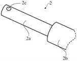
结合图1和图5所示,第一杆件1开设有第一导槽1c,第一导槽1c大致沿第一杆件1的长度方向延伸。第二杆件2插设于第一杆件1中,具体地,第一杆件1开设有插接腔1a,第一导槽1c贯穿插接腔1a的侧壁,以与插接腔1a相连通,第二杆件2可伸缩移动地插设于插接腔1a,继而第二杆件2能够稳定地沿插接腔1a相对第一杆件1移动,以调整截骨导板20的位置。With reference to FIGS. 1 and 5 , the
需要说明的是,第一杆件1和第二杆件2之间也可以不采取插接的配合方式相连接,例如,在一些实施方式中,第一杆件1和第二杆件2之间可滑动低叠设在一起,并被配置为:当第一杆件1和第二杆件2相对滑动时,第一杆件1和第二杆件2的整体长度发生改变。从而通过这种结构形式,也能够通过调整第一杆件1和第二杆件2在长度方向上的相对位置,满足对截骨导板20的位置调整需要,从而使得截骨导板20能够被调整至合适高度进行截骨。第二杆件2上连接有第一轴6,第一轴6插设于第一导槽1c,且能够沿第一导槽1c移动。It should be noted that, the
第一轴6可以是通过焊接或螺纹连接的方式与第二杆件2相连接。在一些实施方式中,第一轴6可以是插接固定于第二杆件2,例如,结合图6所示,第二杆件2上开设有插孔2c,第一轴6插接于插孔2c,以实现第一轴6与第二杆件2的连接。第一轴6也可以是与第二杆件2一体成型的。The
由于第一轴6插设于第一导槽1c并且能够沿第一导槽1c移动,而第一导槽1c大致沿第一杆件1的长度方向延伸,从而第一轴6沿第一导槽1c移动时,与第一轴6相连接的第二杆件2将与第一杆件1彼此相对移动,从而第一杆件1和第二杆件2的结合后的长度将会得到适应性调整,这样分别与第一杆件1和第二杆件2相连接的截骨导板20和抱踝器30之间的距离能够被调整至合适状态,进而截骨导板20的位置进行调整,以适应截骨需要。Since the
继续参阅图1所示,截骨量调整装置10包括调节件3,调节件3通过第一轴6与第二杆件2转动连接。具体地,由于第一轴6插设于第一导槽1c,从而第一轴6的部分结构凸出于第一杆件1的表面。结合图7所示,调节件3上开设有与第一轴6相配合的轴孔3c,第一轴6凸出于第一杆件1的表面的部分结构与轴孔3c相配合。Continuing to refer to FIG. 1 , the osteotomy
调节件3与第一轴6之间可相对转动,或者,第一轴6与第二杆件2之间可相对转动,只要调节件3通过第一轴6与第二杆件2相连接后,调节件3能够相对第二杆件2转动即可,例如,在一些实施例中,第一轴6与调节件3之间以及第一轴6与第二杆件2之间均为转动连接。The
结合图1和图7所示,调节件3上开设有第二导槽3b,第一杆件1设有第二轴7。第二轴7可以是通过插接的方式与第一杆件1相固定,例如,第一杆件1靠近端部位置处设有销孔1b,第二轴7与销孔1b插接配合,以固定在第一杆件1上。在其他实施方式中,第二轴7与第一杆件1螺纹连接、卡接、焊接或一体成型。对于第二轴7与第一杆件1之间的连接方式,在此不做限定。As shown in FIG. 1 and FIG. 7 , the adjusting
以第一轴6与调节件3的交点(即轴孔3c)为圆心,第二导槽3b在各弧度上的半径不同,即第二导槽3b在各弧度上的点到轴孔3c的距离不同,优选为逐步增大或逐步减小。第二轴7插设于第二导槽3b,当调节件3绕第一轴6相对第一杆件1转动时,第二轴7沿第二导槽3b移动并靠近或远离第一轴6,以调整第一杆件1与第二杆件2在轴向上的相对位置,此处轴向是指沿第一杆件1或第二杆件2的长度方向。本文中的第一轴6沿第一导槽1c移动以及第二轴7沿第二导槽3b移动均是指相对移动,即相对移动的两方中的任意一方移动,而另一方静止,也可以是两方均移动。Taking the intersection of the
需要说明的是,第二导槽3b可以是通槽,即贯穿调节件3的外表面。第二导槽3b也可以是盲槽,即不贯穿调节件3的外表面。It should be noted that, the
该实施例中,利用调节件3上的第二导槽3b对第二轴7的约束,使得第二轴7沿第二导槽3b移动时,靠近或远离第一轴6,即第一轴6和第二轴7之间的距离得以调整,第二轴7设置于第一杆件1,从而第一轴6和第二轴7之间的距离变化时,第一轴6沿第一导槽1c移动,这样与第一轴6相连接的第二杆件2将相对第一杆件1移动,从而达到调整第一杆件1和第二杆件2在第一杆件1的长度方向上的相对位置,进而与第一杆件1相连接的截骨导板20相对第二杆件2上移或下移,实现截骨导板20位置调整的目的。第二轴7沿第二导槽3b移动时相对第一轴6的位置变化量是连续的,也即,第一轴6和第二轴7之间的距离能够被精确的控制,从而通过这种截骨量调整装置10调整截骨导板20相对胫骨B的截骨位置时,能够获得精确微调的效果。In this embodiment, the
第二导槽3b可以是圆弧槽。例如,在一些实施方式中,结合图8所示,第二导槽3b为圆弧槽时,第二导槽3b在沿其中线方向上具有相对的第一端部3b1和第二端部3b2,第一端部3b1与第一轴6之间的距离r1为50mm,第二端部3b2到第一轴6之间的距离r2为10mm,r1和r2可取其他数值,只要二者不相等即可。结合图1所示,随着调节件3相对第二杆件2绕第一轴6的轴线转动,在第二轴7沿第二导槽3b由第一端部3b1朝第二端部3b2移动的过程中,第二轴7与第一轴6之间的相对距离逐渐缩小,由于第二轴7与第一杆件1之间的位置固定,从而第一轴6将沿第一导槽1c移动。由于第一轴6与第二杆件2之间的位置固定,从而随着第二轴7与第一轴6之间的相对距离逐渐缩小,第二杆件2与第一杆件1之间相对滑动,达到调整截骨导板20位置的需要。The
在一些实施方式中,结合图8所示,在第二轴7与第二导槽3b的配合限位下,调节件3绕第一轴6的转动幅度β为10°~90°。In some embodiments, as shown in FIG. 8 , under the cooperating limit of the
需要说明的是,调节件3绕第一轴6的转动幅度β是指,通过驱使调节件3绕第一轴6转动使得第二轴7沿第二导槽3b的第一端部3b1运动到第二端部3b2时,调节件3转动的角度。It should be noted that the rotation amplitude β of the adjusting
该实施例中,将调节件3绕第一轴6的转动幅度β控制在10°~90°,能够确保调节件3对第一轴6和第二轴7的相对位置进行调整时,具有足够大的调节行程,以便通过对第一轴6和第二轴7之间相对位置的调整,精确地调整第一杆件1和第二杆件2的相对位置,以适应截骨导板20的位置能够在比较大的范围内精确地移动,提高对截骨量的精准控制。如果转动幅度β小于10°,则第二导槽3b的倾斜过于陡峭,转动调节件3时,对第一轴6和第二轴7之间相对位置的调整变化过快,不利于对截骨量的精确控制。如果转动幅度β大于90°,则调节件3体积太大,不利于整个装置体积的紧凑性。In this embodiment, the rotation range β of the adjusting
再次参阅图1所示,截骨量调整装置10包括止动件4,止动件4能够沿第二杆件2的长度方向移动至与调节件3相抵持,以限制调节件3绕第一轴6转动,且止动件4能够沿第二杆件2的长度方向移动离开调节件3,以解除对调节件3的抵持限位。Referring to FIG. 1 again, the osteotomy
该实施例中,利用止动件4能够锁定好调节件3的位置,从而使得调节件3保持第一轴6和第二轴7的相对位置,进而使得第一杆件1和第二杆件2彼此相固定,以稳定地支撑截骨导板20。在需要对截骨导板20的位置进行调整时,只需要移开止动件4,使得止动件4解除对调节件3的位置锁定,便可以利用调节件3绕第一轴6的轴线转动来调整第一杆件1和第二杆件2的相对位置。In this embodiment, the
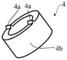
结合图1、图7和图9所示,调节件3设有齿状边缘3a,止动件4包括主体部4b和位于主体部4b的锁止齿4a,当止动件4沿第二杆件2的长度方向移动至于调节件3相抵持时,锁止齿4a与齿状边缘3a相配合,从而锁定调节件3的位置,使得调节件3不能绕第一轴6相对第二杆件2转动,此时第一轴6和第二轴7的相对位置被锁定,以固定截骨导板20的位置。在需要调整截骨导板20的位置时,只需要将止动件4沿第二杆件2的长度方向移动离开调节件3,以解除述锁止齿4a与齿状边缘3a的配合即可。1, 7 and 9, the adjusting
齿状边缘3a的啮合齿沿第一轴6的周向呈圆弧形排布,这样无论调节件3绕第一轴6的轴线转动至何种位置,锁止齿4a均能够与相应的啮合齿稳定啮合,以提高对调节件3的位置的锁定稳定性。The meshing teeth of the
在一些实施方式中,齿状边缘3a的齿顶半径R为15mm~60mm,比如15mm、25mm、35mm、45mm、55mm或60mm。通过将齿状边缘3a的齿顶半径R控制在15mm~60mm,使得调节件3的齿状边缘3a到第一轴6的轴线的距离足够大,以便设置第二导槽3b时,可以将第二导槽3b对第二轴7相对第一轴6的移动的位移量设置的足够大,以提高截骨量的调节范围。同时,调节件3的体积也不至于过大而不利于整个装置的紧凑性。In some embodiments, the tip radius R of the
结合图1和图9所示,止动件4呈环状,止动件4套设于第一杆件1或第二杆件2。Referring to FIGS. 1 and 9 , the
在一些实施方式中,截骨量调整装置10包括弹性件,如弹簧或橡胶等弹性体等等。弹性件设于第一杆件1与止动件4之间,或第二杆件2与止动件4之间,用于将止动件4弹性地抵持于调节件3。设于第一杆件1与止动件4之间是指,弹性件的一端与第一杆件1固定连接或抵接,另一端与止动件4固定连接或抵接。弹性件根据需要设为压缩状态或拉伸状态。In some embodiments, the
可选的,所述弹性件为弹簧5,弹簧5套设于第一杆件1或第二杆件2,并将止动件4弹性地抵持于调节件3。Optionally, the elastic member is a
第一杆件1或第二杆件2设有抵持面,例如阶梯槽或台阶面等。以第二杆件2为例,结合图6所示,第二杆件2包括两段彼此相连且径向尺寸不同的轴体2a、2b,这样,在两段轴体2a、2b的连接面形成台阶面,可选的,该台阶面朝远离轴体2a的方向凹陷,形成阶梯槽。弹簧5收容于阶梯槽,并与槽底面相抵接,这样弹簧5不会过分凸出于第二杆件2的表面,使得截骨量调整装置10的整体结构紧凑、小巧。抵持面的形式不局限于此,只要能保证弹簧5的一端能与其抵接或固定连接即可,例如也可以是设于第一杆件1或第二杆件2的凸缘,此时第一杆件1或第二杆件2不必设为粗细不同的两段。以图1为例,抵持面在止动件4左边时,弹性件设为拉伸状态;抵持面在止动件4右边时,弹性件设为压缩状态。The
结合图1和图7所示,调节件3可以是镜面对称结构,形成有供第二杆件2穿过的避空位304,以便调节件3安装至第一杆件1时,第一杆件1的相对的两侧均具有相应的第二导槽3b、第二轴7等结构,使得调节件3与第一杆件1和第二杆件2之间的组装更为稳定。1 and FIG. 7 , the adjusting
可以理解的是,调节件3呈镜面对称结构并不是必要的,如前述实施例中,只要调节件3能够通过第一轴6与第二杆件2转动连接,并通过设置第二导槽3b引导第二轴7滑动过程中靠近或远离第一轴6,便能够实现第一轴6与第二轴7之间相对距离的调整,以使得第一杆件1和第二杆件2沿第一杆件1的长度方向相对移动,进而调整截骨导板20的位置。It can be understood that it is not necessary for the adjusting
结合图7所示,呈镜面对称结构的调节件3,包括间隔设置的第一导片301和第二导片302,第一导片301和第二导片302之间通过两间隔设置连接臂303相连,两连接臂303与第一导片301和第二导片302围合形成避空位304,调节件3安装至第一杆件1时,第一导片301和第二导片302分别位于第一杆件1的两侧,第二杆件2穿过避空位304并与第一杆件1相配合。Referring to FIG. 7 , the adjusting
第一导片301和第二导片302中的至少一个设置第二导槽3b,与第一杆件1相连接的第二轴7与相应侧的第二导槽3b滑动配合,便能够实现第二轴7沿第二导槽3b滑动过程中靠近或远离第一轴6,满足对第一轴6和第二轴7的之间距离调整。At least one of the
可以理解的是,在调节件3包括第一导片301和第二导片302的实施例中,第一导片301和第二导片302均与第二杆件2转动连接,且转动轴线同轴,从而使得调节件3能够相对第二杆件2转动。第一导片301、第二导片302与第二杆件2之间的转动可以是采取同一个第一轴6,以增强调节件3对第一杆件1和第二杆件2之间位置调整稳定性。在其他实施例中,也可以采取不同的第一轴6,只要与第一导片301、第二导片302相连接的第一轴6同轴设置即可。相应地,调节件3开设轴孔3c的实施例中,轴孔3c可以是设置在第一导片301、第二导片302其中任何一个上,或者,第一导片301、第二导片302上均开设轴孔3c。It can be understood that, in the embodiment in which the adjusting
该实施例中,调节件3的齿状边缘3a可以是位于第一导片301、第二导片302的其中一个上,或者,第一导片301、第二导片302上均设置有齿状边缘3a,只要止动件4上的锁止齿4a能够与相应地齿状边缘3a相啮合对调节件3起到锁止效果即可。例如,结合图7和图9所示,在第一导片301、第二导片302上均设置有齿状边缘3a时,止动件4上至少设有两个锁止齿4,该两个锁止齿4分别与第一导片301、第二导片302上的齿状边缘3a相对应,从而在止动件4对调节件3的位置进行锁定时,这种结构设置能够有效提高锁定稳定性。该实施例中,止动件4也可以只设置一个锁止齿4,只要该锁止齿4能够与第一导片301和第二导片302其中一个的齿状边缘3a相配合,实现对调节件3进行锁定即可。In this embodiment, the
需要说明的是,止动件4的设置位置和结构形式还可以是其它情形。It should be noted that the arrangement position and structural form of the
例如,第一轴6转动连接于调节件3的轴孔3c时,将止动件4设置于第一轴6与调节件3之间,并用于选择性锁定或释放调节件3绕第一轴6的转动自由度,就能够实现对调节件3的位置锁定或释放。For example, when the
再例如,在另一些实施方式中,止动件4可活动地设置于调节件3,并用于选择性地锁定或释放第二轴7沿第二导槽3b的移动自由度。For another example, in other embodiments, the
对于止动件4的结构及其设置位置,在此不作限定,只要止动件4能够对相应的调节件3进行选择性锁定或释放,使得调节件3被锁定时无法相对第二杆件2的转动即可。The structure of the
以上所述实施例的各技术特征可以进行任意的组合,为使描述简洁,未对上述实施例中的各个技术特征所有可能的组合都进行描述,然而,只要这些技术特征的组合不存在矛盾,都应当认为是本说明书记载的范围。The technical features of the above-described embodiments can be combined arbitrarily. For the sake of brevity, all possible combinations of the technical features in the above-described embodiments are not described. However, as long as there is no contradiction between the combinations of these technical features, All should be regarded as the scope described in this specification.
以上所述实施例仅表达了本发明的几种实施方式,其描述较为具体和详细,但并不能因此而理解为对发明专利范围的限制。应当指出的是,对于本领域的普通技术人员来说,在不脱离本发明构思的前提下,还可以做出若干变形和改进,这些都属于本发明的保护范围。因此,本发明专利的保护范围应以所附权利要求为准。The above-mentioned embodiments only represent several embodiments of the present invention, and the descriptions thereof are specific and detailed, but should not be construed as a limitation on the scope of the invention patent. It should be pointed out that for those of ordinary skill in the art, without departing from the concept of the present invention, several modifications and improvements can also be made, which all belong to the protection scope of the present invention. Therefore, the protection scope of the patent of the present invention should be subject to the appended claims.
Claims (11)
Priority Applications (1)
| Application Number | Priority Date | Filing Date | Title |
|---|---|---|---|
| CN202011252828.8ACN114469243B (en) | 2020-11-11 | 2020-11-11 | Tibial osteotomy system and osteotomy amount adjustment device |
Applications Claiming Priority (1)
| Application Number | Priority Date | Filing Date | Title |
|---|---|---|---|
| CN202011252828.8ACN114469243B (en) | 2020-11-11 | 2020-11-11 | Tibial osteotomy system and osteotomy amount adjustment device |
Publications (2)
| Publication Number | Publication Date |
|---|---|
| CN114469243Atrue CN114469243A (en) | 2022-05-13 |
| CN114469243B CN114469243B (en) | 2025-05-30 |
Family
ID=81490992
Family Applications (1)
| Application Number | Title | Priority Date | Filing Date |
|---|---|---|---|
| CN202011252828.8AActiveCN114469243B (en) | 2020-11-11 | 2020-11-11 | Tibial osteotomy system and osteotomy amount adjustment device |
Country Status (1)
| Country | Link |
|---|---|
| CN (1) | CN114469243B (en) |
Citations (13)
| Publication number | Priority date | Publication date | Assignee | Title |
|---|---|---|---|---|
| US4349018A (en)* | 1980-12-29 | 1982-09-14 | Chambers Gary R | Osteotomy apparatus |
| US5395377A (en)* | 1993-09-21 | 1995-03-07 | Petersen; Thomas D. | Extramedullary proximal tibial guide |
| JPH11113940A (en)* | 1997-10-09 | 1999-04-27 | Tsunenori Takei | Resect-assisting utensil for knee joint |
| JP2015192873A (en)* | 2014-03-28 | 2015-11-05 | アルスロデザイン株式会社 | joint replacement surgical instrument |
| CN107007319A (en)* | 2017-05-18 | 2017-08-04 | 聂宇 | Shin bone list condyle osteotomy device |
| CN107233121A (en)* | 2017-07-15 | 2017-10-10 | 常州奥斯迈医疗器械有限公司 | Shin bone adjusts seat |
| CN209018859U (en)* | 2018-08-09 | 2019-06-25 | 林克骨科(中国)有限公司 | Proximal humerus osteotomy guider |
| CN209220411U (en)* | 2018-10-17 | 2019-08-09 | 嘉思特华剑医疗器材(天津)有限公司 | A kind of fixed separate room knee prosthesis replacement Tibial osteotomy guider |
| CN110393571A (en)* | 2019-06-24 | 2019-11-01 | 北京积水潭医院 | Osteotomy guide device for unicompartmental knee arthroplasty |
| CN110870786A (en)* | 2018-09-04 | 2020-03-10 | 苏州微创关节医疗科技有限公司 | Tibial osteotomy block locking device |
| CN211270993U (en)* | 2019-08-07 | 2020-08-18 | 苏州微创关节医疗科技有限公司 | Osteotomy positioning device |
| CN111616770A (en)* | 2020-05-21 | 2020-09-04 | 天衍医疗器材有限公司 | Tibia osteotomy positioning device |
| CN215018425U (en)* | 2020-11-11 | 2021-12-07 | 苏州微创关节医疗科技有限公司 | Tibia osteotomy system and osteotomy amount adjusting device thereof |
- 2020
- 2020-11-11CNCN202011252828.8Apatent/CN114469243B/enactiveActive
Patent Citations (13)
| Publication number | Priority date | Publication date | Assignee | Title |
|---|---|---|---|---|
| US4349018A (en)* | 1980-12-29 | 1982-09-14 | Chambers Gary R | Osteotomy apparatus |
| US5395377A (en)* | 1993-09-21 | 1995-03-07 | Petersen; Thomas D. | Extramedullary proximal tibial guide |
| JPH11113940A (en)* | 1997-10-09 | 1999-04-27 | Tsunenori Takei | Resect-assisting utensil for knee joint |
| JP2015192873A (en)* | 2014-03-28 | 2015-11-05 | アルスロデザイン株式会社 | joint replacement surgical instrument |
| CN107007319A (en)* | 2017-05-18 | 2017-08-04 | 聂宇 | Shin bone list condyle osteotomy device |
| CN107233121A (en)* | 2017-07-15 | 2017-10-10 | 常州奥斯迈医疗器械有限公司 | Shin bone adjusts seat |
| CN209018859U (en)* | 2018-08-09 | 2019-06-25 | 林克骨科(中国)有限公司 | Proximal humerus osteotomy guider |
| CN110870786A (en)* | 2018-09-04 | 2020-03-10 | 苏州微创关节医疗科技有限公司 | Tibial osteotomy block locking device |
| CN209220411U (en)* | 2018-10-17 | 2019-08-09 | 嘉思特华剑医疗器材(天津)有限公司 | A kind of fixed separate room knee prosthesis replacement Tibial osteotomy guider |
| CN110393571A (en)* | 2019-06-24 | 2019-11-01 | 北京积水潭医院 | Osteotomy guide device for unicompartmental knee arthroplasty |
| CN211270993U (en)* | 2019-08-07 | 2020-08-18 | 苏州微创关节医疗科技有限公司 | Osteotomy positioning device |
| CN111616770A (en)* | 2020-05-21 | 2020-09-04 | 天衍医疗器材有限公司 | Tibia osteotomy positioning device |
| CN215018425U (en)* | 2020-11-11 | 2021-12-07 | 苏州微创关节医疗科技有限公司 | Tibia osteotomy system and osteotomy amount adjusting device thereof |
Non-Patent Citations (1)
| Title |
|---|
| 张威;吴厦;孙长鲛;刘璞;景峰;蔡谞;: "标尺测量截骨法在全膝关节置换胫骨平台截骨中的应用", 临床和实验医学杂志, no. 13, 10 July 2020 (2020-07-10)* |
Also Published As
| Publication number | Publication date |
|---|---|
| CN114469243B (en) | 2025-05-30 |
Similar Documents
| Publication | Publication Date | Title |
|---|---|---|
| JP7145239B2 (en) | Osteotomy device and its operation method | |
| CN110477995B (en) | Femur osteotomy distal end alignment positioning device | |
| US8313491B2 (en) | Adjustable femoral resection guide | |
| CN211270993U (en) | Osteotomy positioning device | |
| US20180221973A1 (en) | Surgical saw mount and blade | |
| CN107212912B (en) | Minimally invasive femur distal medullary cavity orientator | |
| JP2007078173A (en) | Turnbuckle | |
| US9545261B2 (en) | Instrument guide | |
| CN114848083A (en) | An osteotomy guide | |
| CN114469243A (en) | Tibial osteotomy system and its osteotomy volume adjustment device | |
| CN112336412A (en) | Osteotomy positioning device | |
| CN220416756U (en) | Quick release plate assembly and tripod | |
| CN113208745B (en) | Thighbone locating rack | |
| CN215018425U (en) | Tibia osteotomy system and osteotomy amount adjusting device thereof | |
| CN115844597B (en) | Elbow joint prosthesis | |
| CN204520919U (en) | Distal femur cutting assembly and the positioner that turns up | |
| KR102675749B1 (en) | Malocclusion Expander | |
| CN217472016U (en) | Intercondylar osteotomy guides and orthopedic surgical instruments | |
| US20220362028A1 (en) | Tibial component | |
| US20240325034A1 (en) | Methods and apparatus for mid-flexion balancing during knee arthroplasty | |
| JP7123067B2 (en) | medical saw template system | |
| CN110693552A (en) | Adjustable Needle Holder | |
| CN105852944B (en) | Distal femur cutting assembly and positioning device of turning up | |
| CN202426641U (en) | Arc-shaped positioning device for half-epiphysis blockade steel plates | |
| CN211356371U (en) | Self-locking wrench, engagement mechanism applying self-locking wrench and operating bed |
Legal Events
| Date | Code | Title | Description |
|---|---|---|---|
| PB01 | Publication | ||
| PB01 | Publication | ||
| SE01 | Entry into force of request for substantive examination | ||
| SE01 | Entry into force of request for substantive examination | ||
| GR01 | Patent grant | ||
| GR01 | Patent grant |