CN114468828B - Cleaning robot and motion control method thereof - Google Patents
Cleaning robot and motion control method thereofDownload PDFInfo
- Publication number
- CN114468828B CN114468828BCN202210112901.4ACN202210112901ACN114468828BCN 114468828 BCN114468828 BCN 114468828BCN 202210112901 ACN202210112901 ACN 202210112901ACN 114468828 BCN114468828 BCN 114468828B
- Authority
- CN
- China
- Prior art keywords
- cleaning
- cleaning element
- cleaned
- bridge
- negative pressure
- Prior art date
- Legal status (The legal status is an assumption and is not a legal conclusion. Google has not performed a legal analysis and makes no representation as to the accuracy of the status listed.)
- Active
Links
Images


Classifications
- A—HUMAN NECESSITIES
- A47—FURNITURE; DOMESTIC ARTICLES OR APPLIANCES; COFFEE MILLS; SPICE MILLS; SUCTION CLEANERS IN GENERAL
- A47L—DOMESTIC WASHING OR CLEANING; SUCTION CLEANERS IN GENERAL
- A47L11/00—Machines for cleaning floors, carpets, furniture, walls, or wall coverings
- A47L11/40—Parts or details of machines not provided for in groups A47L11/02 - A47L11/38, or not restricted to one of these groups, e.g. handles, arrangements of switches, skirts, buffers, levers
- A47L11/4063—Driving means; Transmission means therefor
- A—HUMAN NECESSITIES
- A47—FURNITURE; DOMESTIC ARTICLES OR APPLIANCES; COFFEE MILLS; SPICE MILLS; SUCTION CLEANERS IN GENERAL
- A47L—DOMESTIC WASHING OR CLEANING; SUCTION CLEANERS IN GENERAL
- A47L1/00—Cleaning windows
- A47L1/02—Power-driven machines or devices
- A—HUMAN NECESSITIES
- A47—FURNITURE; DOMESTIC ARTICLES OR APPLIANCES; COFFEE MILLS; SPICE MILLS; SUCTION CLEANERS IN GENERAL
- A47L—DOMESTIC WASHING OR CLEANING; SUCTION CLEANERS IN GENERAL
- A47L11/00—Machines for cleaning floors, carpets, furniture, walls, or wall coverings
- A—HUMAN NECESSITIES
- A47—FURNITURE; DOMESTIC ARTICLES OR APPLIANCES; COFFEE MILLS; SPICE MILLS; SUCTION CLEANERS IN GENERAL
- A47L—DOMESTIC WASHING OR CLEANING; SUCTION CLEANERS IN GENERAL
- A47L11/00—Machines for cleaning floors, carpets, furniture, walls, or wall coverings
- A47L11/02—Floor surfacing or polishing machines
- A47L11/10—Floor surfacing or polishing machines motor-driven
- A47L11/14—Floor surfacing or polishing machines motor-driven with rotating tools
- A47L11/16—Floor surfacing or polishing machines motor-driven with rotating tools the tools being disc brushes
- A47L11/164—Parts or details of the brushing tools
- A—HUMAN NECESSITIES
- A47—FURNITURE; DOMESTIC ARTICLES OR APPLIANCES; COFFEE MILLS; SPICE MILLS; SUCTION CLEANERS IN GENERAL
- A47L—DOMESTIC WASHING OR CLEANING; SUCTION CLEANERS IN GENERAL
- A47L11/00—Machines for cleaning floors, carpets, furniture, walls, or wall coverings
- A47L11/40—Parts or details of machines not provided for in groups A47L11/02 - A47L11/38, or not restricted to one of these groups, e.g. handles, arrangements of switches, skirts, buffers, levers
- A47L11/4002—Installations of electric equipment
- A47L11/4005—Arrangements of batteries or cells; Electric power supply arrangements
- A—HUMAN NECESSITIES
- A47—FURNITURE; DOMESTIC ARTICLES OR APPLIANCES; COFFEE MILLS; SPICE MILLS; SUCTION CLEANERS IN GENERAL
- A47L—DOMESTIC WASHING OR CLEANING; SUCTION CLEANERS IN GENERAL
- A47L11/00—Machines for cleaning floors, carpets, furniture, walls, or wall coverings
- A47L11/40—Parts or details of machines not provided for in groups A47L11/02 - A47L11/38, or not restricted to one of these groups, e.g. handles, arrangements of switches, skirts, buffers, levers
- A47L11/4011—Regulation of the cleaning machine by electric means; Control systems and remote control systems therefor
- A—HUMAN NECESSITIES
- A47—FURNITURE; DOMESTIC ARTICLES OR APPLIANCES; COFFEE MILLS; SPICE MILLS; SUCTION CLEANERS IN GENERAL
- A47L—DOMESTIC WASHING OR CLEANING; SUCTION CLEANERS IN GENERAL
- A47L11/00—Machines for cleaning floors, carpets, furniture, walls, or wall coverings
- A47L11/40—Parts or details of machines not provided for in groups A47L11/02 - A47L11/38, or not restricted to one of these groups, e.g. handles, arrangements of switches, skirts, buffers, levers
- A47L11/4036—Parts or details of the surface treating tools
- A47L11/4038—Disk shaped surface treating tools
- A—HUMAN NECESSITIES
- A47—FURNITURE; DOMESTIC ARTICLES OR APPLIANCES; COFFEE MILLS; SPICE MILLS; SUCTION CLEANERS IN GENERAL
- A47L—DOMESTIC WASHING OR CLEANING; SUCTION CLEANERS IN GENERAL
- A47L11/00—Machines for cleaning floors, carpets, furniture, walls, or wall coverings
- A47L11/40—Parts or details of machines not provided for in groups A47L11/02 - A47L11/38, or not restricted to one of these groups, e.g. handles, arrangements of switches, skirts, buffers, levers
- A47L11/4036—Parts or details of the surface treating tools
- A47L11/4044—Vacuuming or pick-up tools; Squeegees
- A—HUMAN NECESSITIES
- A47—FURNITURE; DOMESTIC ARTICLES OR APPLIANCES; COFFEE MILLS; SPICE MILLS; SUCTION CLEANERS IN GENERAL
- A47L—DOMESTIC WASHING OR CLEANING; SUCTION CLEANERS IN GENERAL
- A47L11/00—Machines for cleaning floors, carpets, furniture, walls, or wall coverings
- A47L11/40—Parts or details of machines not provided for in groups A47L11/02 - A47L11/38, or not restricted to one of these groups, e.g. handles, arrangements of switches, skirts, buffers, levers
- A47L11/4061—Steering means; Means for avoiding obstacles; Details related to the place where the driver is accommodated
- A—HUMAN NECESSITIES
- A47—FURNITURE; DOMESTIC ARTICLES OR APPLIANCES; COFFEE MILLS; SPICE MILLS; SUCTION CLEANERS IN GENERAL
- A47L—DOMESTIC WASHING OR CLEANING; SUCTION CLEANERS IN GENERAL
- A47L11/00—Machines for cleaning floors, carpets, furniture, walls, or wall coverings
- A47L11/40—Parts or details of machines not provided for in groups A47L11/02 - A47L11/38, or not restricted to one of these groups, e.g. handles, arrangements of switches, skirts, buffers, levers
- A47L11/4063—Driving means; Transmission means therefor
- A47L11/4066—Propulsion of the whole machine
- A—HUMAN NECESSITIES
- A47—FURNITURE; DOMESTIC ARTICLES OR APPLIANCES; COFFEE MILLS; SPICE MILLS; SUCTION CLEANERS IN GENERAL
- A47L—DOMESTIC WASHING OR CLEANING; SUCTION CLEANERS IN GENERAL
- A47L11/00—Machines for cleaning floors, carpets, furniture, walls, or wall coverings
- A47L11/40—Parts or details of machines not provided for in groups A47L11/02 - A47L11/38, or not restricted to one of these groups, e.g. handles, arrangements of switches, skirts, buffers, levers
- A47L11/4063—Driving means; Transmission means therefor
- A47L11/4069—Driving or transmission means for the cleaning tools
- A—HUMAN NECESSITIES
- A47—FURNITURE; DOMESTIC ARTICLES OR APPLIANCES; COFFEE MILLS; SPICE MILLS; SUCTION CLEANERS IN GENERAL
- A47L—DOMESTIC WASHING OR CLEANING; SUCTION CLEANERS IN GENERAL
- A47L9/00—Details or accessories of suction cleaners, e.g. mechanical means for controlling the suction or for effecting pulsating action; Storing devices specially adapted to suction cleaners or parts thereof; Carrying-vehicles specially adapted for suction cleaners
- A47L9/02—Nozzles
- A47L9/04—Nozzles with driven brushes or agitators
- A47L9/0461—Dust-loosening tools, e.g. agitators, brushes
- A47L9/0466—Rotating tools
- A47L9/0472—Discs
- A—HUMAN NECESSITIES
- A47—FURNITURE; DOMESTIC ARTICLES OR APPLIANCES; COFFEE MILLS; SPICE MILLS; SUCTION CLEANERS IN GENERAL
- A47L—DOMESTIC WASHING OR CLEANING; SUCTION CLEANERS IN GENERAL
- A47L9/00—Details or accessories of suction cleaners, e.g. mechanical means for controlling the suction or for effecting pulsating action; Storing devices specially adapted to suction cleaners or parts thereof; Carrying-vehicles specially adapted for suction cleaners
- A47L9/28—Installation of the electric equipment, e.g. adaptation or attachment to the suction cleaner; Controlling suction cleaners by electric means
- A47L9/2836—Installation of the electric equipment, e.g. adaptation or attachment to the suction cleaner; Controlling suction cleaners by electric means characterised by the parts which are controlled
- A47L9/2852—Elements for displacement of the vacuum cleaner or the accessories therefor, e.g. wheels, casters or nozzles
- A—HUMAN NECESSITIES
- A47—FURNITURE; DOMESTIC ARTICLES OR APPLIANCES; COFFEE MILLS; SPICE MILLS; SUCTION CLEANERS IN GENERAL
- A47L—DOMESTIC WASHING OR CLEANING; SUCTION CLEANERS IN GENERAL
- A47L2201/00—Robotic cleaning machines, i.e. with automatic control of the travelling movement or the cleaning operation
- A47L2201/04—Automatic control of the travelling movement; Automatic obstacle detection
- A—HUMAN NECESSITIES
- A47—FURNITURE; DOMESTIC ARTICLES OR APPLIANCES; COFFEE MILLS; SPICE MILLS; SUCTION CLEANERS IN GENERAL
- A47L—DOMESTIC WASHING OR CLEANING; SUCTION CLEANERS IN GENERAL
- A47L2201/00—Robotic cleaning machines, i.e. with automatic control of the travelling movement or the cleaning operation
- A47L2201/06—Control of the cleaning action for autonomous devices; Automatic detection of the surface condition before, during or after cleaning
Landscapes
- Engineering & Computer Science (AREA)
- Mechanical Engineering (AREA)
- Cleaning In General (AREA)
- Electric Vacuum Cleaner (AREA)
Abstract
Translated fromChinese
Description
Translated fromChinese技术领域technical field
本发明涉及清洁设备技术领域,特别涉及一种清洁机器人及其运动控制方法。The invention relates to the technical field of cleaning equipment, in particular to a cleaning robot and a motion control method thereof.
背景技术Background technique
中国专利文献CN102920393A公开了一种用于清洁板件的清洁机,其通过在清洁机与板件间形成负压而使得清洁机附着于板件上。具体而言,清洁机包括设置在两个清洁元件之间的连杆臂(即机体),两个清洁元件均固定连接机体,通过驱动模组使得其中一个清洁元件不转动,而驱动另一清洁元件沿第一旋转方向转动,从而在转动的清洁元件与机体间产生扭力,并通过该扭力使机体往第二旋转方向(第二旋转方向与第一旋转方向相反)摆动,籍由交替驱动两个清洁元件转动,从而实现清洁机在板件上扭动式行进。Chinese patent document CN102920393A discloses a cleaning machine for cleaning a board, which makes the cleaning machine adhere to the board by forming a negative pressure between the cleaning machine and the board. Specifically, the cleaning machine includes a link arm (ie, a body) disposed between two cleaning elements, both of which are fixedly connected to the body, and one of the cleaning elements is not rotated by the driving module, while the other is driven to clean The element rotates in the first rotation direction, thereby generating a torsion force between the rotating cleaning element and the body, and through the torsion force, the body swings in the second rotation direction (the second rotation direction is opposite to the first rotation direction), by alternately driving the two cleaning elements. Each cleaning element rotates, so that the cleaning machine travels in a twisting manner on the plate.
中国专利文献CN104414573A公开了一种具有类似结构的擦窗装置,其通过真空泵在吸盘内产生负压将擦窗装置吸附在玻璃上,擦窗装置的吸附转盘通过轴承与机体连接(轴承的外圈与机体固定连接,轴承的内圈与吸附转盘固定连接),控制单元分别控制动力在两个吸附转盘上输出的大小和方向,驱动一对吸附转盘以垂直于玻璃表面的竖直轴为中心旋转或静止,使两者交替成为高速端或低速端,形成转速差,使得擦窗装置产生交替扭转的动作,实现擦窗装置的扭动行走。Chinese patent document CN104414573A discloses a window cleaning device with a similar structure, which generates negative pressure in a suction cup through a vacuum pump to adsorb the window cleaning device on the glass, and the adsorption turntable of the window cleaning device is connected to the body through a bearing (the outer ring of the bearing It is fixedly connected to the body, and the inner ring of the bearing is fixedly connected to the adsorption turntable. The control unit controls the size and direction of the power output on the two adsorption turntables, and drives a pair of adsorption turntables to rotate around the vertical axis perpendicular to the glass surface. Or static, so that the two alternately become the high-speed end or the low-speed end, forming a rotational speed difference, so that the window cleaning device produces an alternate twisting action to realize the twisting walking of the window cleaning device.
现有采用扭动方式行走的清洁机/擦窗装置几乎都采用了与上述专利类似的结构,都是通过两个吸附旋转盘吸附在板件表面并将两个吸附旋转盘刚性连接成一个整体以实现在板件上扭动式行进。也因为如此,几乎所有扭动式清洁设备都要求其工作的板件表面必须是非常平整的平面,当板件出现一定弯曲而形成弧面时,吸附转盘与板件表面的缝隙增大而产生漏气,这就有可能会导致机器在行进过程中掉落。为避免机器掉落情况的发生,通常的手段是设置传感器来监测负压区的压力变化情况,一旦负压区压力超过设定阈值,立即控制机器调头而不再继续往前行进,因此,现有采用扭动式清洁的设备大多不适用于在存在一定弧度的板件表面进行作业。Existing cleaning machines/window cleaning devices that use a twisting way almost all adopt a structure similar to the above-mentioned patent, which is adsorbed on the surface of the board by two adsorption rotating disks and rigidly connected to form a whole. To achieve twisting travel on the plate. Because of this, almost all twist-type cleaning equipment requires that the surface of the plate it works must be a very flat surface. When the plate is bent to a certain extent to form an arc surface, the gap between the adsorption turntable and the surface of the plate increases. Air leaks, which may cause the machine to fall while traveling. In order to avoid the occurrence of the machine falling, the usual method is to set up sensors to monitor the pressure changes in the negative pressure area. Once the pressure in the negative pressure area exceeds the set threshold, the machine will be turned around immediately and will not continue to move forward. Therefore, now Most of the equipment that uses twist cleaning is not suitable for working on the surface of the plate with a certain arc.
发明内容SUMMARY OF THE INVENTION
本发明要解决的技术问题之一是提供一种适用范围更广的清洁机器人。One of the technical problems to be solved by the present invention is to provide a cleaning robot with wider application range.
为了解决上述技术问题,本发明采用如下技术方案:一种清洁机器人,用于清除待清洁表面附着的微粒,包括:清洁元件,用于与待清洁表面接触以执行清洁功能并与待清洁表面界定出至少一腔室;抽吸模组,与所述腔室连通,用于抽取所述腔室内的空气,于所述腔室内形成负压以使得清洁元件被吸附在待清洁表面上;驱动模组,连接所述清洁元件并能够驱动清洁元件以垂直于待清洁表面的轴为旋转轴心进行旋转;控制器,耦接并控制所述抽吸模组和驱动模组;桥架,连接多个清洁元件和驱动模组,且至少一清洁元件被配置为能够相对于桥架偏转,以使得该清洁元件所对应的旋转轴心能够与其它清洁元件所对应的旋转轴心交错而形成夹角。In order to solve the above-mentioned technical problems, the present invention adopts the following technical solutions: a cleaning robot for removing particles attached to the surface to be cleaned, including: a cleaning element for contacting the surface to be cleaned to perform a cleaning function and to define the surface to be cleaned at least one chamber; a suction module, communicated with the chamber, for extracting the air in the chamber, and forming a negative pressure in the chamber so that the cleaning element is adsorbed on the surface to be cleaned; driving the mold a group, connected to the cleaning element and capable of driving the cleaning element to rotate with an axis perpendicular to the surface to be cleaned as the axis of rotation; a controller, coupled to and controlled the suction module and the drive module; a bridge, connected to a plurality of A cleaning element and a driving module, and at least one cleaning element is configured to be deflectable relative to the bridge frame, so that the rotation axis corresponding to the cleaning element can be staggered with the rotation axes corresponding to other cleaning elements to form an included angle.
于一实施例中,该清洁机器人还包括偏转驱动机构,所述偏转驱动机构用于向被配置为能够相对于桥架偏转的清洁元件施加促使其偏转的偏转作用力,以使该清洁元件放置于待清洁表面时,其一侧最先与待清洁表面接触,且该清洁元件被吸附于待清洁表面后,该一侧对待清洁表面的压力大于其其它部位对待清洁表面的压力。In one embodiment, the cleaning robot further includes a yaw drive mechanism for applying a yaw force to the cleaning element configured to deflect relative to the bridge to cause the cleaning element to deflect, so that the cleaning element is placed in the When the surface to be cleaned, one side is first in contact with the surface to be cleaned, and after the cleaning element is adsorbed on the surface to be cleaned, the pressure on the surface to be cleaned on one side is greater than the pressure on the surface to be cleaned at other parts.
于一实施例中,所述多个清洁元件中至少两个清洁元件通过间隔设置的转轴与桥架连接,所述转轴与该至少两个清洁元件所对应的旋转轴心垂直,所述偏转驱动机构用于向该至少两个清洁元件施加促使其偏转的偏转作用力,以使该至少两个清洁元件放置于待清洁表面时,其一侧最先与待清洁表面接触,且该至少两个清洁元件被吸附于待清洁表面后,前述一侧对待清洁表面的压力大于其其它部位对待清洁表面的压力。In one embodiment, at least two cleaning elements in the plurality of cleaning elements are connected to the bridge frame through rotating shafts arranged at intervals, and the rotating shafts are perpendicular to the rotation axes corresponding to the at least two cleaning elements, and the deflection driving mechanism For applying a deflection force to the at least two cleaning elements to cause them to deflect, so that when the at least two cleaning elements are placed on the surface to be cleaned, one side of the at least two cleaning elements contacts the surface to be cleaned first, and the at least two cleaning elements After the component is adsorbed on the surface to be cleaned, the pressure on the surface to be cleaned on the aforesaid side is greater than the pressure on the surface to be cleaned on the other part.
该至少两个清洁元件被吸附在待清洁表面时,该至少两个清洁元件受所述偏转作用力的一侧对待清洁表面的压力大于或小于其其它部位对待清洁表面的压力。When the at least two cleaning elements are adsorbed on the surface to be cleaned, the pressure on the surface to be cleaned on one side of the at least two cleaning elements subjected to the deflection force is greater or less than the pressure on the surface to be cleaned at other parts thereof.
于一实施例中,所述偏转驱动机构包括设置于桥架与相应清洁元件之间的弹性部件,所述弹性部件的两端分别抵靠住桥架和相应清洁元件或者所述弹性部件的两端分别与桥架及相应清洁元件固定连接,并由产生弹性形变的所述弹性部件向被配置为能够相对于桥架偏转的清洁元件施加促使其偏转的偏转作用力。In one embodiment, the deflection driving mechanism includes an elastic member disposed between the bridge frame and the corresponding cleaning element, and two ends of the elastic member respectively abut against the bridge frame and the corresponding cleaning element or the two ends of the elastic member respectively. It is fixedly connected with the bridge frame and the corresponding cleaning element, and a deflection force is applied to the cleaning element configured to be able to deflect relative to the bridge frame by the elastic member which produces elastic deformation to promote the deflection thereof.
于一实施例中,所述偏转驱动机构包括固定安装在桥架以及相应清洁元件上的相互吸引或排斥的磁性组件,籍由所述磁性组件间的吸引或排斥作用向被配置为能够相对于桥架偏转的清洁元件施加促使其偏转的偏转作用力。In one embodiment, the deflection drive mechanism includes magnetic components that are fixedly mounted on the bridge frame and the corresponding cleaning elements to attract or repel each other, and are configured to be able to be relative to the bridge frame by virtue of the attraction or repulsion between the magnetic components. The deflected cleaning elements apply a deflection force that causes them to deflect.
优选地,所述磁性组件中包括电磁铁,所述电磁铁的控制电路耦接于控制器。Preferably, the magnetic assembly includes an electromagnet, and the control circuit of the electromagnet is coupled to the controller.
其中,所述抽吸模组包括与清洁元件等数量的风机或真空泵,各清洁元件与待清洁表面所界定出的腔室彼此独立,所述风机或真空泵一对一连接腔室。The suction module includes the same number of fans or vacuum pumps as the cleaning elements, the chambers defined by each cleaning element and the surface to be cleaned are independent of each other, and the fans or vacuum pumps connect the chambers one-to-one.
另一方面,本发明还涉及上述清洁机器人的运动控制方法,所述清洁机器人的多个清洁元件至少包括1#清洁元件和2#清洁元件,用于使所述清洁机器人于待清洁表面上移动,于一实施例中,包括以下步骤:In another aspect, the present invention also relates to the motion control method of the above cleaning robot, wherein the plurality of cleaning elements of the cleaning robot include at least a 1# cleaning element and a 2# cleaning element, which are used to move the cleaning robot on the surface to be cleaned , in one embodiment, including the following steps:
S01、控制相应的抽吸模组使1#清洁元件与待清洁表面所界定出的腔室的负压大于2#清洁元件与待清洁表面所界定出的腔室的负压,并控制相应的驱动模组沿第一旋转方向向所述1#清洁元件和2#清洁元件施加合适大小的驱动力,使得所述2#清洁元件与桥架以1#清洁元件为中心并沿与第一旋转方向相反的第二旋转方向扭转。S01. Control the corresponding suction module so that the negative pressure of the chamber defined by the 1# cleaning element and the surface to be cleaned is greater than the negative pressure of the chamber defined by the 2# cleaning element and the surface to be cleaned, and control the corresponding The driving module applies a driving force of a suitable size to the 1# cleaning element and the 2# cleaning element along the first rotation direction, so that the 2# cleaning element and the bridge are centered on the 1# cleaning element and along the first rotation direction. The opposite second rotational direction twists.
S02、控制相应的抽吸模组使所述1#清洁元件与待清洁表面所界定出的腔室的负压小于2#清洁元件与待清洁表面所界定出的腔室的负压,并控制相应的驱动模组沿所述第二旋转方向向所述1#清洁元件和2#清洁元件施加合适大小的驱动力,使得所述1#清洁元件与桥架以2#清洁元件为中心并沿与所述第二旋转方向相反的第一旋转方向扭转。S02, control the corresponding suction module so that the negative pressure of the chamber defined by the 1# cleaning element and the surface to be cleaned is less than the negative pressure of the chamber defined by the 2# cleaning element and the surface to be cleaned, and control The corresponding driving module applies a suitable driving force to the 1# cleaning element and the 2# cleaning element along the second rotation direction, so that the 1# cleaning element and the bridge frame are centered on the 2# cleaning element and move along the opposite direction. The second rotational direction is opposite to the first rotational direction twist.
交替执行上述步骤S01和步骤S02。The above steps S01 and S02 are alternately performed.
于另一实施例中,清洁机器人的运动控制是籍由相应的驱动模组同时驱动所述至少两个清洁元件沿合适的方向相对于待清洁表面转动,并通过所述偏转驱动机构向该至少两个清洁元件施加偏转作用力,使得待清洁表面施加于所有清洁元件的全部静摩擦力的合力大于零,借以驱使该清洁机器人沿所述合力的方向直线行进。In another embodiment, the motion control of the cleaning robot is to simultaneously drive the at least two cleaning elements to rotate in a suitable direction relative to the surface to be cleaned by the corresponding driving module, and to the at least two cleaning elements through the deflection driving mechanism. The two cleaning elements exert a deflection force, so that the resultant force of all the static friction forces exerted by the surface to be cleaned on all the cleaning elements is greater than zero, thereby driving the cleaning robot to travel straight in the direction of the resultant force.
优选地,于采用包含电磁铁的磁性组件作为偏转驱动机构的实施例中,是通过以下方式控制清洁机器人的运动:首先,控制相应的抽吸模组使所述至少两个清洁元件中的1#清洁元件与待清洁表面所界定出的腔室的负压大于2#清洁元件与待清洁表面所界定出的腔室的负压,并将与所述1#清洁元件对应的电磁铁的供电电路断开,将与所述2#清洁元件对应的电磁铁的供电电路闭合,仅使所述2#清洁元件的一侧对待清洁表面的压力大于或小于其其它部位对待清洁表面的压力,并控制相应的驱动模组沿第一旋转方向向所述1#清洁元件和所述2#清洁元件施加合适大小的驱动力,使得所述2#清洁元件与桥架以所述1#清洁元件为中心并沿与第一旋转方向相反的第二旋转方向扭转;之后,控制相应的抽吸模组使所述1#清洁元件与待清洁表面所界定出的腔室的负压小于所述2#清洁元件与待清洁表面所界定出的腔室的负压,并将与所述1#清洁元件对应的电磁铁的供电电路闭合,将与所述2#清洁元件对应的电磁铁的供电电路断开,仅使所述1#清洁元件的一侧对待清洁表面的压力大于或小于其其它部位对待清洁表面的压力,并控制相应的驱动模组沿所述第二旋转方向向1#清洁元件和2#清洁元件施加合适大小的驱动力,使得所述1#清洁元件与桥架以2#清洁元件为中心并沿与所述第二旋转方向相反的第一旋转方向扭转;交替执行上述步骤,实现清洁机器人在待清洁表面扭动式行进。Preferably, in the embodiment using a magnetic assembly including an electromagnet as the deflection drive mechanism, the movement of the cleaning robot is controlled in the following manner: first, controlling the corresponding suction module to make 1 of the at least two cleaning elements # The negative pressure of the chamber defined by the cleaning element and the surface to be cleaned is greater than the negative pressure of the chamber defined by the
与现有的机器不同,本发明将至少一清洁元件配置为能够相对于桥架偏转,相应地,机器的其它部分(包括桥架、其它的清洁元件等)也能够相对于该清洁元件进行偏转。采用可偏转/浮动的结构能够使清洁元件更好地贴合存在一定弧度的待清洁表面,在提高清洁元件与待清洁表面吸附效果、减少机器掉落的同时,能够更好地保证清洁效果。另外,现有的机器在对平整的待清洁表面进行清洁作业时,若待清洁表面存在难以擦除的固体附着物(如固化的水泥块、硬胶块等),即便固体附着物凸起于待清洁表面的高度并不高,机器也会因清洁元件受上述固体附着物的干涉推挤而将固体附着物所处部位误判为板件边界(为防止机器掉落),而本发明可以通过清洁元件的偏转/浮动结构在一定程度范围内避让固体附着物,由此减少上述因干涉而导致误判的情形。综上,本发明较现有的清洁机器人具有更好的适应性,其适用范围更广。Unlike existing machines, the present invention configures at least one cleaning element to be deflectable relative to the bridge, and correspondingly, other parts of the machine (including the bridge, other cleaning elements, etc.) are also deflectable relative to the cleaning element. The deflectable/floating structure can make the cleaning element better fit the surface to be cleaned with a certain arc, improve the adsorption effect of the cleaning element and the surface to be cleaned, reduce the drop of the machine, and better ensure the cleaning effect. In addition, when the existing machine cleans the flat surface to be cleaned, if there are solid attachments (such as solidified cement blocks, hard glue blocks, etc.) that are difficult to remove on the surface to be cleaned, even if the solid attachments protrude above The height of the surface to be cleaned is not high, and the machine will also misjudge the position of the solid attachment as the board boundary (to prevent the machine from falling) because the cleaning element is interfered and pushed by the above-mentioned solid attachment, and the present invention can The deflecting/floating structure of the cleaning element avoids solid attachments to a certain extent, thereby reducing the above-mentioned situation of misjudgment caused by interference. To sum up, the present invention has better adaptability than the existing cleaning robot, and has a wider application range.
附图说明Description of drawings
图1为实施例1-2中的清洁机器人的外形结构示意图;Fig. 1 is the outline structure schematic diagram of the cleaning robot in embodiment 1-2;
图2为实施例1中清洁元件、驱动模组、抽吸模组及桥架之间的连接结构示意图;2 is a schematic diagram of the connection structure between the cleaning element, the drive module, the suction module and the bridge in Example 1;
图3为实施例1中桥架的立体示意图;Fig. 3 is the three-dimensional schematic diagram of the bridge in
图4为实施例1中清洁机器人的俯视示意图;4 is a schematic top view of the cleaning robot in
图5为图4中A-A方向的剖视示意图;Fig. 5 is the sectional schematic diagram of A-A direction in Fig. 4;
图6为实施例1中清洁机器人的侧视示意图;6 is a schematic side view of the cleaning robot in Example 1;
图7为实施例1中清洁机器人被吸附于弧形待清洁表面的示意图;7 is a schematic diagram of the cleaning robot being adsorbed on the curved surface to be cleaned in Example 1;
图8为实施例1中清洁机器人在待清洁表面的运动轨迹示意图;8 is a schematic diagram of the motion trajectory of the cleaning robot on the surface to be cleaned in
图9为实施例2中清洁元件、驱动模组、抽吸模组及桥架之间的连接结构示意图;9 is a schematic diagram of the connection structure between the cleaning element, the drive module, the suction module and the bridge in Example 2;
图10为图9中I部位的局部放大图;Fig. 10 is a partial enlarged view of part I in Fig. 9;
图11为实施例2中桥架的立体示意图;11 is a perspective view of a bridge in
图12为实施例2中清洁机器人的侧视示意图;12 is a schematic side view of the cleaning robot in Example 2;
图13为实施例2中清洁机器人在待清洁表面的运动轨迹示意图一;13 is a schematic diagram 1 of the movement trajectory of the cleaning robot on the surface to be cleaned in
图14为实施例2中清洁机器人在待清洁表面的运动轨迹示意图二。FIG. 14 is a second schematic diagram of the movement trajectory of the cleaning robot on the surface to be cleaned in
图中:In the picture:
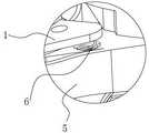
1——清洁元件 2——抽吸模组1 - Cleaning element 2 - Suction module
3——驱动模组 4——控制器3 - drive module 4 - controller
5——桥架 6——偏转驱动机构5 - Bridge 6 - Deflection drive mechanism
7——转轴 1a——腔室7——Rotary shaft 1a——Chamber
1-1——1#清洁元件 1-2——2#清洁元件。1-1——1# cleaning element 1-2——2# cleaning element.
具体实施方式Detailed ways
在本发明的描述中,需要理解的是,术语“中心”、 “上”、“下”、 “前”、“后”、“顶”、“底”、“内”、 “外”等指示的方位或位置关系为基于附图所示的方位或位置关系,仅是为了便于描述本发明和简化描述,而不是指示或暗示所指的装置或元件必须具有特定的方位、以特定的方位构造和操作,因此不能理解为对本发明的限制。此外,术语“1#”、“2#”等仅用于描述目的,而不能理解为指示或暗示相对重要性或者隐含指明所指示的技术特征的数量。In the description of the present invention, it is to be understood that the terms "center", "upper", "lower", "front", "rear", "top", "bottom", "inner", "outer", etc. indicate The orientation or positional relationship is based on the orientation or positional relationship shown in the accompanying drawings, which is only for the convenience of describing the present invention and simplifying the description, rather than indicating or implying that the referred device or element must have a specific orientation or be constructed in a specific orientation. and operation, and therefore should not be construed as limiting the present invention. In addition, the terms "1#", "2#", etc. are only used for descriptive purposes and should not be construed as indicating or implying relative importance or implying the number of indicated technical features.
为了便于本领域技术人员更清楚地理解本发明的构思,下面结合实施例和附图来对其作更进一步的说明。In order to facilitate those skilled in the art to understand the concept of the present invention more clearly, further description will be made below with reference to the embodiments and accompanying drawings.
实施例1Example 1
图1、4、6示出了本实施中清洁机器人的外形结构,结合图2、5、7可知,该清洁机器人主要包括清洁元件1、抽吸模组2、驱动模组3、控制器4和桥架5(桥架5相当于一连接各清洁元件1的支架,由于各清洁元件1彼此独立,该支架将各个独立的清洁元件1相连,起到了类似于连接桥的作用,故称为 “桥架”)。需要提前指出的是,虽然在上述图中清洁元件1的数量为两个,但是本领域技术人员应当明白,在实际应用时,也可以根据需要将清洁元件1的数量配置为多个,图中示出的只是清洁机器人最简单的一种结构。另外,上述抽吸模组2包括但不限于是风机(负压风机)或真空泵,驱动模组3可以是电机(当然也可以根据需要在电机的输出端连接一减速机)。由于本实施例所涉清洁机器人的风道及控制电路与现有的清洁机器人类似,出于简化表述的目的,对于上述内容不再赘述。Figures 1, 4, and 6 show the external structure of the cleaning robot in this implementation. In combination with Figures 2, 5, and 7, it can be seen that the cleaning robot mainly includes a
在以上图示的清洁机器人中,清洁元件1的作用主要是与待清洁表面接触以执行清洁功能并与待清洁表面界定出至少一腔室1a。清洁元件1除可以采用如图所示的轮盘形状外,也可以采用勒洛三角形的形状。另外,本领域技术人员应当明白,前面所述的待清洁表面包括但不限于平整板件的表面(例如直立的玻璃窗户),其也可以是地板表面,抑或是带有一定弧度的曲面(例如类似于汽车前挡一样存在一定弧度的玻璃表面)。于本实施例中,清洁元件1是通过抽吸模组2实现吸附于待清洁表面,具体而言,抽吸模组2包括两个负压风机,两个清洁元件1所形成的腔室1a彼此独立,两个负压风机与两个腔室1a一对一连接,负压风机工作时抽取腔室1a内的空气,于腔室1a内形成负压,从而使得对应的清洁元件1被吸附在待清洁表面上。各清洁元件1分别采用单独的负压风机且其所对应的腔室1a也彼此独立后,各清洁元件1所受吸附力互不影响,即便某一清洁元件1移动至待清洁表面的工作区域之外而发生漏气,只要有一个清洁元件1处在安全工作区内,处于安全工作区内的清洁元件1仍会被牢牢吸附在待清洁面上,不会产生机器掉落的风险,安全性更高。另外,清洁元件1执行清洁功能是通过与其连接的驱动模组3来提供动力,驱动模组3驱动清洁元件1以垂直于待清洁表面的轴为旋转轴心进行旋转,使得清洁元件1与待清洁表面产生相当位移,在摩擦作用下,清洁元件1将待清洁表面附着的微粒擦除。与现有的清洁机器人一样,上述抽吸模组2和驱动模组3可以通过可充电的电池模组来供电,也可以设置外接市电的电源线,通过降压处理后的市电来供电,在采用市电供电时,电池模组可以作为备用电源,在市电断电(例如停电)时,抽吸模组2和驱动模组3切换至电池模组供电。同时,控制器4与抽吸模组2、驱动模组3耦接以实现对抽吸模组2和驱动模组3的控制。与现有的清洁机器人通过机体/机壳将各吸附转盘固定连接成一个整体不同,本实施例中是通过桥架5连接两个清洁元件1,两个清洁元件1均被配置为能够相对于桥架5偏转。具体而言,该两个清洁元件1是通过桥架5上平行间隔设置的两组转轴7分别与桥架5连接,图中转轴7与两个清洁元件1所对应的旋转轴心垂直。任意一个清洁元件1偏转后,其所对应的旋转轴心会与另一清洁元件1所对应的旋转轴心交错而形成夹角。清洁元件1采用上述可相对于桥架3偏转/浮动的结构的目的主要是让其能够更好地贴合存在一定弧度的待清洁表面,以提高清洁元件1与待清洁表面吸附效果、减少机器掉落、保证清洁效果,并且通过清洁元件1的偏转/浮动能够在一定程度范围内避让存在于待清洁表面上的固体附着物,减少上述因固体附着物与清洁元件1发生干涉推挤而导致机器将固体附着物所处部位误判为边界的情形。应当明确的是,于另一实施例中,也可以仅将其中一个清洁元件1配置为能够相对于桥架偏转,根据运动的相对性原理,以该清洁元件1为参照物时,机器的其它部分(包括桥架5、其它的清洁元件1等)也能够相对于该清洁元件1进行偏转,这样同样可以实现上述目的。In the cleaning robot shown above, the function of the
接下来详细介绍上述清洁机器人的运动控制方式,为便于表述,下面将图中两个清洁元件1分别编号为1#清洁元件1-1、2#清洁元件1-2。Next, the motion control mode of the above cleaning robot will be described in detail. For convenience of description, the two
见图8所示,在清洁机器人通过抽吸模组2产生的负压被吸附于待清洁表面后,1#清洁元件1-1及2#清洁元件1-2分别处于图中A0位置和B0位置。As shown in FIG. 8 , after the negative pressure generated by the cleaning robot through the
先通过分别控制与1#清洁元件1-1及2#清洁元件1-2相对应的抽吸模组2,使1#清洁元件1-1所对应的腔室1a的负压大于2#清洁元件1-2所对应的腔室1a的负压,并控制相应的驱动模组3沿顺时针方向驱动1#清洁元件1-1和2#清洁元件1-2,驱动模组3所施加的驱动力应当在合适的范围之内,对于1#清洁元件1-1而言,驱动模组3施加的驱动力应当小于其与待清洁表面的最大静摩擦力,而对于2#清洁元件1-2而言,驱动模组3施加的驱动力应当大于其与待清洁表面的最大静摩擦力,以使得2#清洁元件1-2以垂直于待清洁表面的轴为旋转轴心进行旋转,2#清洁元件1-2与待清洁表面发生相对位移,而1#清洁元件1-1则相对于待清洁表面保持静止,根据作用力与反作用力原理,施加于1#清洁元件1-1的驱动力所对应的反作用力(该反作用力等于待清洁表面产生的静摩擦力)将传导至桥架5,由于发生转动的2#清洁元件1-2与待清洁表面的滑动摩擦力小于1#清洁元件1-1与待清洁表面的静摩擦力,在上述反作用力驱使下,桥架5连同2#清洁元件1-2将以1#清洁元件1-1为中心并沿逆时针方向扭转,使得2#清洁元件1-2移动至B1位置,1#清洁元件1-1仍处于A0位置。First, by controlling the
之后再分别控制与1#清洁元件1-1及2#清洁元件1-2相对应的抽吸模组2,使1#清洁元件1-1所对应的腔室1a的负压小于2#清洁元件1-2所对应的腔室1a的负压,并控制相应的驱动模组3沿逆时针方向驱动1#清洁元件1-1和2#清洁元件1-2,与前面的步骤类似,驱动模组3所施加的驱动力也应当在合适的范围之内,与前述步骤不同之处在于,在本步骤中,对于1#清洁元件1-1而言,驱动模组3施加的驱动力应当大于其与待清洁表面的最大静摩擦力,而对于2#清洁元件1-2而言,驱动模组3施加的驱动力应当小于其与待清洁表面的最大静摩擦力,以使得1#清洁元件1-1以垂直于待清洁表面的轴为旋转轴心进行旋转,1#清洁元件1-1与待清洁表面发生相对位移,而2#清洁元件1-2则相对于待清洁表面保持静止,根据作用力与反作用力原理,施加于2#清洁元件1-2的驱动力所对应的反作用力(该反作用力等于待清洁表面产生的静摩擦力)将传导至桥架5,由于发生转动的1#清洁元件1-1与待清洁表面的滑动摩擦力小于2#清洁元件1-2与待清洁表面的静摩擦力,在上述反作用力驱使下,桥架5连同1#清洁元件1-1将以2#清洁元件1-2为中心并沿顺时针方向扭转,使得1#清洁元件1-1移动至A1位置,2#清洁元件1-2仍处于B1位置。After that, control the
通过交替执行上述两个步骤,就可以实现清洁机器人在待清洁表面上扭动式行进。在清洁机器人于待清洁表面上扭动式行进的过程中,1#清洁元件1-1和2#清洁元件1-2交替相对于待清洁表面转动并将待清洁表面附着的赃物微粒擦除,从而实现对待清洁表面的清洁作业。By alternately performing the above two steps, the cleaning robot can move in a twisting manner on the surface to be cleaned. During the twisting process of the cleaning robot on the surface to be cleaned, the 1# cleaning element 1-1 and the 2# cleaning element 1-2 alternately rotate relative to the surface to be cleaned and wipe off the dirt particles attached to the surface to be cleaned, This enables cleaning of the surface to be cleaned.
实施例2Example 2
本实施例中清洁机器人也采用了如图1所示的外形结构,结合图9可以看出,与实施例1类似,该清洁机器人同样主要包括清洁元件1、抽吸模组2、驱动模组3、控制器4和桥架5。参照图9-11所示,本实施例中两个清洁元件1均被配置为能够相对于桥架5偏转,同样地,两个清洁元件1也都是通过桥架5上平行间隔设置的两组转轴7分别与桥架5连接且转轴7与两个清洁元件1所对应的旋转轴心垂直。In this embodiment, the cleaning robot also adopts the shape structure shown in FIG. 1 . It can be seen from FIG. 9 that, similar to
本实施例与实施例1最大的不同之处在于还设置有用于向两个被配置为能够相对于桥架5偏转的清洁元件1施加促使其偏转的偏转作用力的偏转驱动机构6,籍由该偏转驱动机构6施加的偏转作用力,以使两个清洁元件1放置于待清洁表面时,其一侧最先与待清洁表面接触,且在该两个清洁元件1被吸附于待清洁表面后,前述一侧(即最先与待清洁表面接触的一侧)对待清洁表面的压力大于其其它部位对待清洁表面的压力。具体而言,本实施例于桥架5与两个清洁元件1之间分别设置偏转驱动机构6,见图9和图10所示,偏转驱动机构6为设置于桥架5与清洁元件1之间的螺旋弹簧,该螺旋弹簧的下端抵靠在桥架5端头处所设置的定位孔中,该螺旋弹簧的上端抵靠在清洁元件1靠近桥架5处所设置的定位孔中,且使该螺旋弹簧处于压缩状态(压簧)。在不受其它外力作用下,如图12所示,该清洁机器人的一个清洁元件1受对应压簧的弹力作用相对于桥架5沿逆时针方向偏转,另一个清洁元件1受对应压簧的弹力作用相对于桥架5沿顺时针方向偏转,使得清洁元件1所对应的旋转轴心交错而形成夹角。应当指出的是,螺旋弹簧并不局限于上述设置方式,其也可以被设置为上端固定连接桥架5的端头、下端与清洁元件1靠近桥架5的部位固定连接,使该螺旋弹簧处于拉伸状态(拉簧),籍由该拉簧的弹力作用,同样可以使得一个清洁元件1相对于桥架5沿逆时针方向偏转,另一个清洁元件1相对于桥架5沿顺时针方向偏转,而呈现如图12所示的状态。The biggest difference between this embodiment and
接下来详细介绍本实施例中清洁机器人的运动控制方式,为便于表述,将图中两个清洁元件1分别编号为1#清洁元件1-1、2#清洁元件1-2。见图13所示,本实施例的清洁机器人可以采用与实施例1一样的方式对其工作过程的运行轨迹进行控制。与实施例1一样,在清洁机器人通过抽吸模组2产生的负压被吸附于待清洁表面后,1#清洁元件1-1及2#清洁元件1-2分别处于图中A0位置和B0位置。此时1#清洁元件1-1及2#清洁元件1-2远端(1#清洁元件1-1及2#清洁元件1-2距离桥架5相对远的一端,即图12中1#清洁元件1-1及2#清洁元件1-2最低点的位置)对待清洁表面的压力大于其其它部位对待清洁表面的压力。Next, the motion control mode of the cleaning robot in this embodiment is described in detail. For convenience of description, the two
参照实施例1中的控制步骤,通过驱使1#清洁元件1-1及2#清洁元件1-2扭动式行进,使得1#清洁元件1-1及2#清洁元件1-2分别对应移动至图中A1位置和B1位置。如图13所示,在清洁机器人于待清洁表面上扭动式行进的过程中,1#清洁元件1-1和2#清洁元件1-2交替相对于待清洁表面转动并将待清洁表面附着的赃物微粒擦除,从而实现对待清洁表面的清洁作业。与实施例1不同,本实施例通过设置向清洁元件1施加偏转作用力的螺旋弹簧,使得1#清洁元件1-1及2#清洁元件1-2被吸附在待清洁表面时,其远端侧对待清洁表面的压力大于其其它部位对待清洁表面的压力,这样在1#清洁元件1-1和2#清洁元件1-2相对于待清洁面转动的过程中,待清洁面施加于该远端侧的反作用力大于其它部位所受反作用力,也就是说,该转动的清洁元件1(1#清洁元件1-1或2#清洁元件1-2)所受到的来自于待清洁面的反作用力不平衡,相当于待清洁面施加于整个清洁元件1的反作用力形成了一个致使清洁元件1偏转的作用力,从而使得该清洁元件1更易于实现以另一相对于待清洁面静止的清洁元件1为中心偏转。由于偏转更容易,能够大大减少机器在行进过程中扭力过大导致从待清洁面掉落的情况,同时也可以对应降低驱动模组3施加于相对静止侧的清洁元件1的驱动力,并相应降低抽吸模组2的输出功率,通过采用更低功率的抽吸模组2和驱动模组3,能够节省清洁机器人的制造成本,降低清洁机器人行进过程所需能耗,实现一举多得的效果。Referring to the control steps in Example 1, the 1# cleaning element 1-1 and the 2# cleaning element 1-2 are driven to move in a twisting manner, so that the 1# cleaning element 1-1 and the 2# cleaning element 1-2 move correspondingly respectively to position A1 and position B1 in the figure. As shown in FIG. 13 , in the process of the cleaning robot twisting on the surface to be cleaned, 1# cleaning element 1-1 and 2# cleaning element 1-2 alternately rotate relative to the surface to be cleaned and attach the surface to be cleaned Cleans the surface to be cleaned by removing the dirt particles. Different from
除上述运动控制方式之外,本实施例的清洁机器人也可以用于对水平的待清洁表面(例如地板)进行清洁。如图14所示,籍由相应的驱动模组3同时驱动1#清洁元件1-1及2#清洁元件1-2沿相反方向(一个沿逆时针方向,另一个沿顺时针方向)相对于待清洁表面转动,1#清洁元件1-1及2#清洁元件1-2在各自所对应螺旋弹簧同时施加的偏转作用力下,待清洁表面施加于1#清洁元件1-1及2#清洁元件1-2的全部静摩擦力的合力大于零并指向清洁机器人的一侧,从而使得该清洁机器人沿合力的方向直线行进。当然将上述两种方式结合到一起来对清洁机器人的运动轨迹进行控制。In addition to the above motion control methods, the cleaning robot of this embodiment can also be used to clean a horizontal surface to be cleaned (eg, a floor). As shown in FIG. 14 , the 1# cleaning element 1-1 and the 2# cleaning element 1-2 are simultaneously driven in opposite directions (one in the counterclockwise direction and the other in the clockwise direction) relative to the The surface to be cleaned rotates, and the 1# cleaning element 1-1 and 2# cleaning element 1-2 are applied to the 1# cleaning element 1-1 and 2# cleaning element under the deflection force exerted by the corresponding coil springs at the same time. The resultant force of all the static frictional forces of elements 1-2 is greater than zero and points to one side of the cleaning robot, so that the cleaning robot travels straight in the direction of the resultant force. Of course, the above two methods are combined to control the movement trajectory of the cleaning robot.
需要强调的是,前述偏转驱动机构6并不局限于螺旋弹簧的结构,其也可以是其它弹性部件,还可以是除弹性部件之外的其它能够设置在桥架5于清洁元件1之间并向清洁元件1施加偏转作用力的部件。于一实施例中,偏转驱动机构6可以是固定安装在桥架5以及相应清洁元件1上的相互吸引(相对于拉簧)或排斥(相当于压簧)的磁性组件,籍由磁性组件间的吸引或排斥作用同样能够向清洁元件1施加偏转作用力。优选地,该磁性组件中包括电磁铁,电磁铁的控制电路耦接于控制器4,由控制器4可以控制电磁铁的电流通断,来实现对偏转驱动机构6的调控。采用电磁铁作为偏转驱动机构6后,可以通过以下方式来实现让清洁机器人于待清洁表面扭动式行进:首先,控制相应的抽吸模组3使1#清洁元件1-1所对应腔室1a的负压大于2#清洁元件1-2所对应腔室1a的负压,并将与1#清洁元件1-1对应的电磁铁的供电电路断开,将与2#清洁元件1-2对应的电磁铁的供电电路闭合,仅使2#清洁元件1-2的一侧对待清洁表面的压力大于或小于其其它部位对待清洁表面的压力,并控制相应的驱动模组3沿顺时针方向向1#清洁元件1-1和2#清洁元件1-2施加合适大小的驱动力,本实施例中所谓驱动力“合适”的要求与实施例1一致(即让一个清洁元件1相对于待清洁表面静止,另一清洁元件1相对于待清洁表面转动),使得2#清洁元件1-2与桥架5以1#清洁元件1-1为中心并沿逆时针方向扭转。然后,控制相应的抽吸模组3使1#清洁元件1-1所对应腔室1a的负压小于2#清洁元件1-2所对应腔室1a的负压,并将与1#清洁元件1-1对应的电磁铁的供电电路闭合,将与2#清洁元件1-2对应的电磁铁的供电电路断开,仅使1#清洁元件1-1的一侧对待清洁表面的压力大于或小于其其它部位对待清洁表面的压力,并控制相应的驱动模组3沿逆时针方向向1#清洁元件1-1和2#清洁元件1-2施加合适大小的驱动力,使得1#清洁元件1-1与桥架5以2#清洁元件1-2为中心并沿顺时针方向扭转。交替执行上述步骤,即可控制清洁机器人在待清洁表面扭动式行进。由于采用电磁铁后,能够在扭动式行进过程中实现相对于待清洁表面静止清洁元件1不受偏转作用力,而仅仅使相对于待清洁表面转动清洁元件1受偏转作用力,静止的清洁元件1受力均衡并牢牢吸附于待清洁表面,仅有转动的清洁元件1所受到的来自于待清洁面的反作用力不平衡,在让该转动的清洁元件1更易于实现以另一相对于待清洁面静止的清洁元件1为中心偏转的同时,进一步降低了清洁机器人在扭动式行进过程中从待清洁表面掉落的风险。It should be emphasized that the aforementioned
上述实施例为本发明较佳的实现方案,在不脱离本技术方案构思的前提下任何显而易见的替换均在本发明的保护范围之内。The above-mentioned embodiments are the preferred implementation solutions of the present invention, and any obvious replacements are within the protection scope of the present invention without departing from the concept of the technical solution.
为了让本领域普通技术人员更方便地理解本发明相对于现有技术的改进之处,本发明的一些附图和描述已经被简化,并且为了清楚起见,本申请文件还省略了一些其它元素,本领域普通技术人员应该意识到这些省略的元素也可构成本发明的内容。In order to make it easier for those skilled in the art to understand the improvements of the present invention relative to the prior art, some drawings and descriptions of the present invention have been simplified, and for the sake of clarity, some other elements are also omitted in this application document, One of ordinary skill in the art would realize that these omitted elements may also constitute the subject matter of the present invention.
Claims (9)
Priority Applications (8)
| Application Number | Priority Date | Filing Date | Title |
|---|---|---|---|
| CN202210112901.4ACN114468828B (en) | 2022-01-29 | 2022-01-29 | Cleaning robot and motion control method thereof |
| US18/009,179US20240225399A1 (en) | 2022-01-29 | 2022-03-17 | Cleaning robot and motion control method thereof |
| AU2022437586AAU2022437586B2 (en) | 2022-01-29 | 2022-03-17 | Cleaning robot and motion control method thereof |
| EP22813078.7AEP4241639B1 (en) | 2022-01-29 | 2022-03-17 | Cleaning robot and motion control method thereof |
| JP2024534543AJP2024545173A (en) | 2022-01-29 | 2022-03-17 | Cleaning robot and its motion control method |
| PCT/CN2022/081489WO2023142243A1 (en) | 2022-01-29 | 2022-03-17 | Cleaning robot and motion control method thereof |
| KR1020247019442AKR20240141159A (en) | 2022-01-29 | 2022-03-17 | Cleaning robot and its movement control method |
| ZA2024/04078AZA202404078B (en) | 2022-01-29 | 2024-05-24 | Cleaning robot and motion control method thereof |
Applications Claiming Priority (1)
| Application Number | Priority Date | Filing Date | Title |
|---|---|---|---|
| CN202210112901.4ACN114468828B (en) | 2022-01-29 | 2022-01-29 | Cleaning robot and motion control method thereof |
Publications (2)
| Publication Number | Publication Date |
|---|---|
| CN114468828A CN114468828A (en) | 2022-05-13 |
| CN114468828Btrue CN114468828B (en) | 2022-10-21 |
Family
ID=81478064
Family Applications (1)
| Application Number | Title | Priority Date | Filing Date |
|---|---|---|---|
| CN202210112901.4AActiveCN114468828B (en) | 2022-01-29 | 2022-01-29 | Cleaning robot and motion control method thereof |
Country Status (8)
| Country | Link |
|---|---|
| US (1) | US20240225399A1 (en) |
| EP (1) | EP4241639B1 (en) |
| JP (1) | JP2024545173A (en) |
| KR (1) | KR20240141159A (en) |
| CN (1) | CN114468828B (en) |
| AU (1) | AU2022437586B2 (en) |
| WO (1) | WO2023142243A1 (en) |
| ZA (1) | ZA202404078B (en) |
Families Citing this family (6)
| Publication number | Priority date | Publication date | Assignee | Title |
|---|---|---|---|---|
| CN114794993A (en)* | 2022-06-28 | 2022-07-29 | 山西嘉世达机器人技术有限公司 | Control method and device of cleaning machine, control equipment and storage medium |
| CN114794995A (en)* | 2022-06-28 | 2022-07-29 | 山西嘉世达机器人技术有限公司 | Method and device for adjusting negative pressure in cleaning machine, cleaning machine and storage medium |
| CN114794994B (en)* | 2022-06-28 | 2022-11-15 | 山西嘉世达机器人技术有限公司 | Cleaning device |
| CN115969257B (en)* | 2023-03-07 | 2025-08-19 | 衡阳慧迪智能科技有限公司 | Bias pressing structure, method and cleaning robot |
| TWI863811B (en)* | 2023-07-24 | 2024-11-21 | 好樣科技有限公司 | Window cleaning machine |
| CN117484524B (en)* | 2023-12-22 | 2025-03-18 | 衡阳慧迪智能科技有限公司 | Cleaning Robot |
Family Cites Families (32)
| Publication number | Priority date | Publication date | Assignee | Title |
|---|---|---|---|---|
| GB9211146D0 (en)* | 1992-05-26 | 1992-07-08 | O C S Group Limited | Improvements in window cleaning |
| US5440216A (en)* | 1993-06-08 | 1995-08-08 | Samsung Electronics Co., Ltd. | Robot cleaner |
| US5890250A (en)* | 1996-02-02 | 1999-04-06 | Sky Robitics, Inc. | Robotic washing apparatus |
| EP1123033B1 (en)* | 1999-08-25 | 2004-11-03 | Koninklijke Philips Electronics N.V. | Surface-cleaning device with rotatable and pivotable cleaning part |
| RU2220643C2 (en)* | 2001-04-18 | 2004-01-10 | Самсунг Гванджу Электроникс Ко., Лтд. | Automatic cleaning apparatus, automatic cleaning system and method for controlling of system (versions) |
| US8099818B2 (en)* | 2002-09-24 | 2012-01-24 | Tohru Miyake | Window wiping system |
| US8790468B2 (en)* | 2007-07-13 | 2014-07-29 | Sky Robotics, Inc. | Stabilized vertical surface cleaning |
| KR101240732B1 (en)* | 2005-02-18 | 2013-03-07 | 아이로보트 코퍼레이션 | Autonomous surface cleaning robot for wet and dry cleaning |
| DE602007007026D1 (en)* | 2006-09-05 | 2010-07-22 | Lg Electronics Inc | cleaning robot |
| US8151401B2 (en)* | 2007-10-25 | 2012-04-10 | Brian Cheyne | Variable strength magnetic window cleaning device |
| EP2446793B1 (en)* | 2010-04-09 | 2013-10-16 | Intellectual Discovery Co., Ltd. | Glass window cleaning device and a control method therefor |
| KR101081927B1 (en)* | 2010-05-15 | 2011-11-09 | 주식회사 일심글로발 | Window cleaning apparatus and its movement control method |
| US8435359B2 (en)* | 2010-06-17 | 2013-05-07 | Chi-Mou Chao | Cleaner and path controlling method thereof |
| TWI434738B (en)* | 2011-08-09 | 2014-04-21 | Chi Mou Chao | Cleaner and path controlling method thereof |
| CN103356120B (en)* | 2012-04-05 | 2015-08-19 | 科沃斯机器人有限公司 | There is the glass cleaning device of adsorbent equipment |
| CN103505143A (en)* | 2012-06-28 | 2014-01-15 | 科沃斯机器人科技(苏州)有限公司 | Glass cleaning robot and walking method thereof |
| CN103505140B (en)* | 2012-06-28 | 2016-12-21 | 科沃斯机器人股份有限公司 | Glass cleaning device |
| KR102015319B1 (en)* | 2013-01-16 | 2019-08-29 | 삼성전자주식회사 | Robot cleaner |
| CN104414573B (en)* | 2013-08-23 | 2017-12-22 | 科沃斯机器人股份有限公司 | Window cleaning device |
| KR102117263B1 (en)* | 2013-12-30 | 2020-06-01 | 삼성전자주식회사 | Robot cleaner |
| US9215962B2 (en)* | 2014-03-13 | 2015-12-22 | Ecovacs Robotics, Inc. | Autonomous planar surface cleaning robot |
| KR20150107398A (en)* | 2014-03-14 | 2015-09-23 | 에브리봇 주식회사 | A robot cleaner and a method for operating it |
| CN104930226B (en)* | 2014-03-17 | 2019-04-19 | 科沃斯家用机器人有限公司 | Air release valve for adsorption device and adsorption robot with air release valve |
| KR101689133B1 (en)* | 2014-06-02 | 2016-12-26 | 에브리봇 주식회사 | A robot cleaner and a method for operating it |
| KR20160104429A (en)* | 2015-02-26 | 2016-09-05 | 에브리봇 주식회사 | A robot cleaner and a method for operating it |
| GB201521712D0 (en)* | 2015-12-09 | 2016-01-20 | F Robotics Acquisitions Ltd | Window cleaning robot |
| WO2018012914A1 (en)* | 2016-07-14 | 2018-01-18 | 엘지전자 주식회사 | Cleaner |
| CN110537867B (en)* | 2018-05-29 | 2021-11-26 | 好样科技有限公司 | Spray module and robot with same |
| CN108903762B (en)* | 2018-08-08 | 2024-02-20 | 宁波史河机器人科技有限公司 | Cleaning robot |
| CN113475982A (en)* | 2021-07-27 | 2021-10-08 | 汤恩智能科技(常熟)有限公司 | Cleaning robot, cleaning assembly thereof and adjusting method of cleaning assembly |
| CN113455953A (en)* | 2021-07-28 | 2021-10-01 | 罗积川 | Cleaning device and walking control method thereof |
| CN217118327U (en)* | 2022-01-29 | 2022-08-05 | 衡南艾迪智能科技中心 | Connection structure and cleaning machines people between cleaning module group |
- 2022
- 2022-01-29CNCN202210112901.4Apatent/CN114468828B/enactiveActive
- 2022-03-17KRKR1020247019442Apatent/KR20240141159A/enactivePending
- 2022-03-17JPJP2024534543Apatent/JP2024545173A/enactivePending
- 2022-03-17WOPCT/CN2022/081489patent/WO2023142243A1/ennot_activeCeased
- 2022-03-17EPEP22813078.7Apatent/EP4241639B1/enactiveActive
- 2022-03-17USUS18/009,179patent/US20240225399A1/ennot_activeAbandoned
- 2022-03-17AUAU2022437586Apatent/AU2022437586B2/enactiveActive
- 2024
- 2024-05-24ZAZA2024/04078Apatent/ZA202404078B/enunknown
Also Published As
| Publication number | Publication date |
|---|---|
| CN114468828A (en) | 2022-05-13 |
| US20240225399A1 (en) | 2024-07-11 |
| AU2022437586B2 (en) | 2025-08-14 |
| EP4241639A1 (en) | 2023-09-13 |
| JP2024545173A (en) | 2024-12-05 |
| AU2022437586A1 (en) | 2024-05-23 |
| ZA202404078B (en) | 2025-01-29 |
| KR20240141159A (en) | 2024-09-25 |
| WO2023142243A1 (en) | 2023-08-03 |
| EP4241639B1 (en) | 2025-09-10 |
| EP4241639A4 (en) | 2024-02-28 |
Similar Documents
| Publication | Publication Date | Title |
|---|---|---|
| CN114468828B (en) | Cleaning robot and motion control method thereof | |
| CN109549607B (en) | Shoe washing mechanism for shoe washing machine and shoe washing machine | |
| CN103505142B (en) | Glass-cleaning robot | |
| CN110255239B (en) | Cloth rolling edulcoration device | |
| CN103505143A (en) | Glass cleaning robot and walking method thereof | |
| CN109528109B (en) | Automatic cleaning device for outer vertical surface of building with crawler-type wall-climbing robot | |
| CN210436135U (en) | Track rail transfer device and track | |
| CN105919502A (en) | Parallelogram glass wiping device and travel method implemented by same | |
| CN113498995A (en) | Double-adsorption type multi-direction movable obstacle-surmounting wall surface cleaning robot | |
| CN217118327U (en) | Connection structure and cleaning machines people between cleaning module group | |
| CN208084334U (en) | A kind of SCARA robots | |
| WO2025130813A1 (en) | Cleaning robot | |
| CN202889481U (en) | Spherical camera | |
| CN211658046U (en) | Running gear and surface cleaning equipment | |
| CN218044985U (en) | Cleaning robot | |
| CN110682324A (en) | A flexible robotic arm joint that can rotate at all angles | |
| CN111287127A (en) | A new type of cleaning machine floating device | |
| CN111137368B (en) | A glass curtain wall climbing mechanism | |
| CN223287076U (en) | Cleaning robot | |
| CN220972211U (en) | Disassembling device and disassembling system | |
| CN208453120U (en) | A suction cup crawler fast breaking negative pressure mechanism | |
| CN217827677U (en) | Drive module of window cleaning robot and window cleaning robot | |
| CN112205932B (en) | Intelligent floor sweeping robot | |
| CN115339538B (en) | Bionic peristaltic robot driven by dielectric elastomer | |
| CN111336007B (en) | An air-cooled engine unit with broken belt protection |
Legal Events
| Date | Code | Title | Description |
|---|---|---|---|
| PB01 | Publication | ||
| PB01 | Publication | ||
| SE01 | Entry into force of request for substantive examination | ||
| SE01 | Entry into force of request for substantive examination | ||
| GR01 | Patent grant | ||
| GR01 | Patent grant |