CN114468363A - Heating and baking low-temperature smoking set - Google Patents
Heating and baking low-temperature smoking setDownload PDFInfo
- Publication number
- CN114468363A CN114468363ACN202011256670.1ACN202011256670ACN114468363ACN 114468363 ACN114468363 ACN 114468363ACN 202011256670 ACN202011256670 ACN 202011256670ACN 114468363 ACN114468363 ACN 114468363A
- Authority
- CN
- China
- Prior art keywords
- heating
- electrode
- heating element
- base
- insulating thin
- Prior art date
- Legal status (The legal status is an assumption and is not a legal conclusion. Google has not performed a legal analysis and makes no representation as to the accuracy of the status listed.)
- Granted
Links
- 238000010438heat treatmentMethods0.000titleclaimsabstractdescription162
- 230000000391smoking effectEffects0.000titleclaimsabstractdescription28
- 238000009434installationMethods0.000claimsabstractdescription32
- 235000019505tobacco productNutrition0.000claimsabstractdescription24
- 238000005192partitionMethods0.000claimsdescription19
- 230000007246mechanismEffects0.000claimsdescription13
- 238000007789sealingMethods0.000claimsdescription13
- 230000002093peripheral effectEffects0.000claimsdescription6
- 239000000758substrateSubstances0.000claims1
- 235000019504cigarettesNutrition0.000description14
- 239000000779smokeSubstances0.000description7
- 238000000034methodMethods0.000description5
- 238000003466weldingMethods0.000description5
- 238000010586diagramMethods0.000description4
- 239000003571electronic cigaretteSubstances0.000description4
- 241000208125NicotianaSpecies0.000description3
- 235000002637Nicotiana tabacumNutrition0.000description3
- 238000003780insertionMethods0.000description3
- 230000037431insertionEffects0.000description3
- 238000012423maintenanceMethods0.000description3
- 239000000463materialSubstances0.000description3
- KDLHZDBZIXYQEI-UHFFFAOYSA-NPalladiumChemical compound[Pd]KDLHZDBZIXYQEI-UHFFFAOYSA-N0.000description2
- 238000002485combustion reactionMethods0.000description2
- 239000000306componentSubstances0.000description2
- 238000013461designMethods0.000description2
- 239000000428dustSubstances0.000description2
- 230000000694effectsEffects0.000description2
- 239000007788liquidSubstances0.000description2
- 230000008569processEffects0.000description2
- HBBGRARXTFLTSG-UHFFFAOYSA-NLithium ionChemical compound[Li+]HBBGRARXTFLTSG-UHFFFAOYSA-N0.000description1
- 230000002411adverseEffects0.000description1
- 230000009286beneficial effectEffects0.000description1
- 230000005540biological transmissionEffects0.000description1
- 238000004140cleaningMethods0.000description1
- 230000006835compressionEffects0.000description1
- 238000007906compressionMethods0.000description1
- 239000004020conductorSubstances0.000description1
- 239000008358core componentSubstances0.000description1
- 230000002950deficientEffects0.000description1
- 238000009826distributionMethods0.000description1
- 238000001704evaporationMethods0.000description1
- 238000004880explosionMethods0.000description1
- 239000007789gasSubstances0.000description1
- 239000001257hydrogenSubstances0.000description1
- 229910052739hydrogenInorganic materials0.000description1
- 230000003993interactionEffects0.000description1
- 229910001416lithium ionInorganic materials0.000description1
- 238000004519manufacturing processMethods0.000description1
- 239000011159matrix materialSubstances0.000description1
- 229910052751metalInorganic materials0.000description1
- 239000002184metalSubstances0.000description1
- 238000012986modificationMethods0.000description1
- 230000004048modificationEffects0.000description1
- 229910052763palladiumInorganic materials0.000description1
- 230000008439repair processEffects0.000description1
- 238000000926separation methodMethods0.000description1
- 229910052709silverInorganic materials0.000description1
- 239000004332silverSubstances0.000description1
- 235000019640tasteNutrition0.000description1
- 238000009966trimmingMethods0.000description1
Images


Classifications
- A—HUMAN NECESSITIES
- A24—TOBACCO; CIGARS; CIGARETTES; SIMULATED SMOKING DEVICES; SMOKERS' REQUISITES
- A24F—SMOKERS' REQUISITES; MATCH BOXES; SIMULATED SMOKING DEVICES
- A24F40/00—Electrically operated smoking devices; Component parts thereof; Manufacture thereof; Maintenance or testing thereof; Charging means specially adapted therefor
- A24F40/40—Constructional details, e.g. connection of cartridges and battery parts
- A24F40/46—Shape or structure of electric heating means
- A—HUMAN NECESSITIES
- A24—TOBACCO; CIGARS; CIGARETTES; SIMULATED SMOKING DEVICES; SMOKERS' REQUISITES
- A24F—SMOKERS' REQUISITES; MATCH BOXES; SIMULATED SMOKING DEVICES
- A24F40/00—Electrically operated smoking devices; Component parts thereof; Manufacture thereof; Maintenance or testing thereof; Charging means specially adapted therefor
- A24F40/50—Control or monitoring
- A—HUMAN NECESSITIES
- A24—TOBACCO; CIGARS; CIGARETTES; SIMULATED SMOKING DEVICES; SMOKERS' REQUISITES
- A24F—SMOKERS' REQUISITES; MATCH BOXES; SIMULATED SMOKING DEVICES
- A24F40/00—Electrically operated smoking devices; Component parts thereof; Manufacture thereof; Maintenance or testing thereof; Charging means specially adapted therefor
- A24F40/85—Maintenance, e.g. cleaning
Landscapes
- Resistance Heating (AREA)
Abstract
Translated fromChinese
Description
Translated fromChinese技术领域technical field
本发明属于吸烟用品技术领域,尤其涉及一种加热烘焙低温烟具。The invention belongs to the technical field of smoking articles, in particular to a heating and baking low-temperature smoking article.
背景技术Background technique
目前市场上的电子烟具主要包括两种类型,比如通过蒸发烟油形成可抽吸烟雾的电子烟和通过低温(150-300度)加热/蒸馏烟草材料形成可抽吸烟雾的低温烟,与传统的燃烧型卷烟相比,电子烟与低温烟工作温度低,其所采用的烟油或低温烟支所产生的烟雾中的有害成分要远远少于传统的燃烧型卷烟,因此,使用电子烟或低温烟能够极大的避免香烟对人体的不利影响。At present, there are mainly two types of electronic cigarettes on the market, such as electronic cigarettes that can be smoked by evaporating e-liquid and low-temperature cigarettes that can be smoked by heating/distilling tobacco materials at low temperature (150-300 degrees). Compared with conventional combustion cigarettes, the working temperature of electronic cigarettes is lower than that of low temperature cigarettes, and the harmful components in the smoke produced by the e-liquid or low temperature cigarettes used are far less than those of traditional combustion cigarettes. Therefore, the use of electronic cigarettes or Low temperature smoke can greatly avoid the adverse effects of cigarettes on the human body.
发热元件是加热不燃烧烟具的核心部件,其一般分为中心加热的片状、棒状加热元件以及包围加热的管状加热元件。目前市场上中心加热的发热体通过焊盘与电源的导线连接,如果发热体出现故障时,需要将热体拆卸下来,经过修整后再重新进行焊接,维修过程较为繁琐,而且重复焊接增加了焊接不良、虚焊等问题出现的概率。The heating element is the core component of the heat-not-burn smoking device, which is generally divided into a centrally heated sheet-shaped heating element, a rod-shaped heating element, and a surrounding heating tubular heating element. At present, the centrally heated heating element on the market is connected to the wire of the power supply through the pad. If the heating element fails, the heating element needs to be disassembled, and then re-welded after trimming. The maintenance process is cumbersome, and repeated welding increases the amount of welding. The probability of problems such as bad and false welding.
发明内容SUMMARY OF THE INVENTION
本发明的主要目的在于提供一种发热体拆卸方便的加热烘焙低温烟具。The main purpose of the present invention is to provide a heating and baking low-temperature smoking tool with convenient disassembly of the heating element.
为解决上述技术问题,本发明采用如下技术方案:In order to solve the above-mentioned technical problems, the present invention adopts the following technical solutions:
一种加热烘焙低温烟具,包括壳体,所述加热腔中设有供所述发热体插置安装的安装腔,所述安装腔内固定设有与所述壳体内的电源连接的电极柱和导电弹片,所述导电弹片围绕所述电极柱布置多片;A low-temperature smoking appliance for heating and baking, comprising a housing, an installation cavity for inserting and installing the heating element is arranged in the heating cavity, and an electrode column and a power supply in the housing are fixedly arranged in the installation cavity. a conductive elastic sheet, wherein a plurality of conductive elastic sheets are arranged around the electrode column;
所述发热体上设有第一电极和第二电极,且所述发热体上设有安装孔;The heating body is provided with a first electrode and a second electrode, and the heating body is provided with a mounting hole;
所述发热体可拆卸的插在所述安装腔中时,所述导电弹片与所述发热体侧壁上的第一电极弹性接触,所述电极柱插入所述发热体上的安装孔中并与所述第二电极接触。When the heating element is detachably inserted into the installation cavity, the conductive elastic sheet is in elastic contact with the first electrode on the side wall of the heating element, and the electrode post is inserted into the installation hole on the heating element and in contact with the second electrode.
具体的,所述电极柱插入所述安装孔后与所述发热体螺纹固定连接。Specifically, the electrode post is inserted into the mounting hole and is threadedly connected to the heating element.
具体的,所述加热腔具有相对的第一端和第二端;其中,所述第一端用于插入所述烟草制品,所述第二端内匹配滑动安装有基座,所述壳体内设有带动所述基座在所述加热腔中来回移动的线性驱动机构;Specifically, the heating chamber has an opposite first end and a second end; wherein, the first end is used for inserting the tobacco product, a base is slidably installed in the second end, and a base is installed in the casing. a linear drive mechanism for driving the base to move back and forth in the heating chamber;
所述加热腔内位于所述第一端和第二端之间还设有带有通孔的分隔板,所述发热体匹配穿过所述通孔后固定在所述基座上的所述安装腔中。There is also a partition plate with a through hole in the heating chamber between the first end and the second end, and the heating body matches all the parts fixed on the base after passing through the through hole. into the installation cavity.
具体的,所述基座与所述分隔板之间设有弹性密封体,所述基座具有第一位置和第二位置;其中,Specifically, an elastic sealing body is arranged between the base and the partition plate, and the base has a first position and a second position; wherein,
当所述基座位于所述第一位置时,所述基座靠近所述分隔板,并且挤压所述弹性密封体将所述通孔密封;When the base is located at the first position, the base is close to the partition plate, and the elastic sealing body is pressed to seal the through hole;
当所述基座位于所述第二位置时,所述基座远离所述分隔板,所述发热体未脱离所述通孔。When the base is located at the second position, the base is away from the partition plate, and the heat generating body is not separated from the through hole.
具体的,所述弹性密封体固定设置在所述分隔板上。Specifically, the elastic sealing body is fixedly arranged on the partition plate.
具体的,所述线性驱动机构包括驱动电机、丝杆以及丝杆滑块,所述基座与所述丝杆滑块连接,所述驱动电机驱动所述丝杆旋转以带动所述丝杆滑块和所述基座线性移动。Specifically, the linear drive mechanism includes a drive motor, a lead screw, and a lead screw slider, the base is connected to the lead screw slider, and the drive motor drives the lead screw to rotate to drive the lead screw to slide. The block and the base move linearly.
具体的,所述发热体呈棒状,所述第一电极环绕所述发热体的外壁设置一圈。Specifically, the heating body is in the shape of a rod, and the first electrode is arranged in a circle around the outer wall of the heating body.
具体的,所述第二电极设置在所述发热体内部,所述电极柱插入所述安装孔后直接与所述第二电极螺纹连接。Specifically, the second electrode is disposed inside the heating body, and the electrode post is directly connected with the second electrode after being inserted into the mounting hole.
具体的,所述发热体包括绝缘薄壁管、设置在所述绝缘薄壁管外周壁上的电阻线路以及覆盖所述电阻线路的绝缘层,所述第二电极固定设置在所述绝缘薄壁管内,所述第一电极和第二电极分别与所述电阻线路的两端连接。Specifically, the heating element includes an insulating thin-walled tube, a resistance line arranged on the outer peripheral wall of the insulating thin-walled tube, and an insulating layer covering the resistance line, and the second electrode is fixedly arranged on the insulating thin-walled Inside the tube, the first electrode and the second electrode are respectively connected with two ends of the resistance line.
具体的,所述第二电极的顶端呈锥形并匹配延伸至所述绝缘薄壁管外。Specifically, the top end of the second electrode is tapered and extends to the outside of the insulating thin-walled tube.
具体的,所述电阻线路覆盖整个绝缘薄壁管的外周壁,所述绝缘薄壁管的两端设有与所述电阻线路的两端连接的连接电极;其中,Specifically, the resistance line covers the entire outer peripheral wall of the insulating thin-walled tube, and both ends of the insulating thin-walled tube are provided with connection electrodes connected to both ends of the resistance line; wherein,
位于所述绝缘薄壁管尾端的所述连接电极构成所述第一电极,位于所述绝缘薄壁管前端的所述连接电极与所述第二电极电连接。The connecting electrode located at the tail end of the insulating thin-walled tube constitutes the first electrode, and the connecting electrode located at the front end of the insulating thin-walled tube is electrically connected to the second electrode.
具体的,所述绝缘薄壁管与顶部的连接电极位置对应处设有至少一个穿孔,所述穿孔中填充有将所述连接电极与所述第二电极连通的导电基质。Specifically, the insulating thin-walled tube is provided with at least one perforation corresponding to the position of the connection electrode at the top, and the perforation is filled with a conductive matrix that communicates the connection electrode with the second electrode.
与现有技术相比,本发明具有的有益效果在于:在安装腔的中心设置电极柱,在电极柱的同轴外圈设有若干导电弹片,电极柱和导电弹片分别通过导线与电源的两极连接,发热体插入安装腔后,电极柱的螺纹端与发热体的第二电极上的螺纹孔连接,在导通发热体其中一极的同时,将发热体牢固可靠的安装在烟具中;电极柱外圈的导电弹片与发热体侧部的第一电极弹性接触,实现发热体的另一极导通,在生产和维修过程中可以将发热体从安装腔中旋松拔出,从而实现不良品的维修或更换,而且发热体省略了连接导线,不会出现导线焊接不良、虚焊等问题。Compared with the prior art, the present invention has the beneficial effects that an electrode post is arranged in the center of the installation cavity, and a plurality of conductive elastic sheets are arranged on the coaxial outer ring of the electrode post, and the electrode post and the conductive elastic sheets pass through the wires and the two poles of the power supply respectively. After the heating element is inserted into the installation cavity, the threaded end of the electrode column is connected with the threaded hole on the second electrode of the heating element. While conducting one of the poles of the heating element, the heating element is firmly and reliably installed in the smoking set; the electrode The conductive elastic sheet of the outer ring of the column is in elastic contact with the first electrode on the side of the heating body to realize the conduction of the other pole of the heating body. Repair or replacement of good products, and the heating body omits the connecting wires, so there will be no problems such as poor wire welding and virtual welding.
附图说明Description of drawings
为了更清楚地说明本发明实施例中的技术方案,下面将对实施例描述中所需要使用的附图作简单地介绍,显而易见地,下面描述中的附图仅仅是本发明的一些实施例,对于本领域普通技术人员来讲,在不付出创造性劳动的前提下,还可以根据这些附图获得其他的附图。In order to illustrate the technical solutions in the embodiments of the present invention more clearly, the following briefly introduces the accompanying drawings used in the description of the embodiments. Obviously, the accompanying drawings in the following description are only some embodiments of the present invention. For those of ordinary skill in the art, other drawings can also be obtained from these drawings without creative effort.
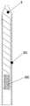
图1是本发明实施例提供的加热烘焙低温烟具结构示意图;1 is a schematic structural diagram of a heating and baking low-temperature smoking set provided by an embodiment of the present invention;
图2是本发明实施例提供的加热烘焙低温烟具局部示意图;Fig. 2 is a partial schematic diagram of a heating and baking low-temperature smoking device provided by an embodiment of the present invention;
图3是本发明实施例提供的加热烘焙低温烟具爆炸示意图;Fig. 3 is the explosion schematic diagram of the heating and baking low-temperature smoking tool provided by the embodiment of the present invention;
图4是本发明实施例涉及的发热体结构示意图;4 is a schematic structural diagram of a heating body involved in an embodiment of the present invention;
图5是本发明实施例涉及的发热体剖视示意图;5 is a schematic cross-sectional view of a heating element involved in an embodiment of the present invention;
其中:1-壳体;101-中间壳;102-顶盖;103-底盖;2-发热体;201-绝缘薄壁管;202-电阻线路;203-连接电极;3-电源;4-电路板;5-第一电极;6-第二电极;601-螺纹连接孔;7-加热腔;8-烟草制品;9-安装腔;10-电极柱;11-导电弹片;12-分隔板;13-弹性密封体;14-滑盖;15-滑槽;16-移动滑块;17-基座;18-磁铁;19-按键;20-线性驱动机构;2001-驱动电机;2002-丝杆;2003-丝杆滑块;21-连接导线。Among them: 1-shell; 101-middle shell; 102-top cover; 103-bottom cover; 2-heating body; 201-insulating thin-walled tube; 202-resistance line; 203-connecting electrode; 3-power supply; 4- circuit board; 5-first electrode; 6-second electrode; 601-threaded connection hole; 7-heating cavity; 8-tobacco product; 9-installation cavity; 10-electrode column; 11-conductive elastic sheet; 12-separation plate; 13-elastic sealing body; 14-slide cover; 15-chute; 16-moving slider; 17-base; 18-magnet; 19-key; 20-linear drive mechanism; 2001-drive motor; 2002- Screw; 2003-screw slider; 21-connecting wire.
具体实施方式Detailed ways
下面将结合本发明实施例中的附图,对本发明实施例中的技术方案进行清楚、完整地描述,显然,所描述的实施例仅仅是本发明一部分实施例,而不是全部的实施例。基于本发明中的实施例,本领域普通技术人员在没有作出创造性劳动前提下所获得的所有其他实施例,都属于本发明保护的范围。The technical solutions in the embodiments of the present invention will be clearly and completely described below with reference to the accompanying drawings in the embodiments of the present invention. Obviously, the described embodiments are only a part of the embodiments of the present invention, rather than all the embodiments. Based on the embodiments of the present invention, all other embodiments obtained by those of ordinary skill in the art without creative efforts shall fall within the protection scope of the present invention.
参见图1-图5,一种加热烘焙低温烟具,包括壳体1、发热体2、电源3和电路板4,发热体2、电源3和电路板4均设置在壳体1中,发热体2具有向其供应电力的第一电极5和第二电极6,第一电极5和第二电极6通过连接导线21与电路板4连接,电路板4与电源3连接,进而共同组成控制发热体加热的控制电路,在壳体1上还设有实现人机交互的按键19。在壳体1内形成有用于容置烟草制品8的加热腔7,烟草制品8可以插入加热腔7中,并可以从加热腔7中移出,发热体2设置在加热腔7中,通电时可以对加热腔7中的烟草制品8加热,以产生供用户抽吸的烟雾,烟草制品8可以为低温烟支或烟弹等结构,电源3可以采用锂离子电池、氢镍电池或其他能量体。Referring to Figures 1 to 5, a heating and baking low-temperature smoking device includes a
参见图1-图3,具体的,加热腔7上设有供发热体2插置安装的安装腔9,安装腔9内固定设有与壳体1内的电源3连接的电极柱10和导电弹片11,电极柱10设置在安装腔9的中部,导电弹片11围绕电极柱10布置多片,发热体2上设有安装孔,发热体2可拆卸的插在安装腔9中时,导电弹片11与发热体2侧壁上的第一电极5弹性接触,电极柱10插入发热体2上的安装孔中并与第二电极6接触,实现电路导通。1-3, specifically, the
具体的,在电极柱10上设有连接螺纹,第一电极5设置在发热体2的尾端(也即安装端)侧壁上,第二电极6设置在发热体2的内部,在发热体2安装孔底端设有螺纹连接孔601,发热体2安装在安装腔9中时,电极柱10插入螺纹连接孔601并与之螺纹连接,从而将发热体2牢固固定在安装腔9中。需要说明的是,发热体2在烟具中的安装部分,其连接方式并不仅限于螺纹连接,还可以是卡扣等其他可拆卸连接方式。Specifically, the
在实际应用中,第二电极6可以设置在螺纹连接孔601的底端,发热体2旋拧到位后,电极柱10与第二电极6接触,当然,本实施例中,为保证连接的可靠性,螺纹连接孔601直接设置在第二电极6上,也就是说只要电极柱10旋入螺纹连接孔601中,就实现了电极柱10与第二电极6电性导通,从而保证发热体供电电路的电性连接的可靠性,不易出现电路连接故障。In practical applications, the
本实施例中,在安装腔9的中心设置电极柱10,在电极柱10的同轴外圈设有若干导电弹片11,电极柱10和导电弹片11分别通过导线与电源3的两极连接,发热体2插入安装腔9后,电极柱10的螺纹端与发热体2的第二电极6上的螺纹孔连接,在导通发热体2其中一极的同时,将发热体2牢固可靠的安装在烟具中;电极柱10外圈的导电弹片11与发热体2侧部的第一电极5弹性接触,实现发热体2的另一极导通,在生产和维修过程中可以将发热体2从安装腔9中旋松拔出,从而实现不良品的维修或更换,而且发热体2省略了连接导线,不会出现导线焊接不良、虚焊等问题。In this embodiment, an
参见图1-图3,在一些可能实施的方案中,加热腔7具有相对的第一端和第二端;其中,第一端用于插入烟草制品8,第二端内匹配滑动安装有基座17,壳体1内设有带动基座17在加热腔7中来回移动的线性驱动机构20,发热体2通过线性驱动机构20的带动可以在加热腔7中移动,加热腔7内位于第一端和第二端之间还设有带有通孔的分隔板12,发热体2匹配穿过通孔后固定在基座17上的安装腔9中。1-3, in some possible implementations, the
通过上述设置,烟草制品8插入加热腔7后,发热体2刺入烟草制品8中对发烟材料加热以产生供用户抽吸的烟雾,当抽吸完成后需要拔出烟草制品8时,先利用线性驱动机构20带动发热体2从烟草制品8中退出,然后再拔出烟草制品8,从而可以有效避免烟丝在发热体2上产生过多的残留,减轻清洗发热体2的负担。Through the above arrangement, after the
参见图1-图3,可以理解的是,在实际应用中,在基座17与分隔板12之间设有弹性密封体13,基座17通过线性驱动机构20的带动可以在第一位置和第二位置之间移动;其中,当基座17位于第一位置时,基座17靠近分隔板12,并且挤压弹性密封体13将通孔密封,此时发热体2插入第一端中,烟草制品8插入第一端时,发热体2可以刺入烟草制品8中,当基座17位于第二位置时,基座17远离分隔板12运动,发热体2从第一端内退出,但是未完全脱离通孔。Referring to FIGS. 1-3 , it can be understood that, in practical applications, an
上述方案通过在分隔板12和基座17之间设置弹性密封体13,当基座17移动至第一位置时,发热体2穿过通孔插在第一端中,而基座17挤压弹性密封体13将通孔密封,此时在加热腔7的第一端中插入烟草制品8,并利用发热体2加热烟草制品8产生烟雾,用户抽吸时,气体从烟草制品8与加热腔7的第一端之间的间隙进入,从烟草制品8内部流出,形成特定气流通道,烟具内部气体不能从通孔中进入第一端,抽吸的烟草口味更纯正。此外,因基座17回退至位于第二位置时,发热体2未完全脱离通孔,这样的方式使得烟草制品8拔出时脱落的少量残渣不会经通孔进入烟具其他部分。In the above solution, the
参见图1-图3,具体的,本实施例中弹性密封体13直接设置在分隔板12面向第二端的端面上,当然,也可以将弹性密封体13设置在基座17面向分隔板12的端面上。1-3, specifically, in this embodiment, the
可以理解的是,当通孔开设于分隔板12的中心处时,发热体2基本位于加热腔7的中心位置,可以向外围均匀发散加热。此外,为方便发热体2插入烟草制品8中,发热体2可以设计成棒状,在发热体2的顶部还可以设置尖刺端,第一电极5环绕发热体2的外壁设置一圈,从而可以保证发热体安装时,无论旋拧多少角度,第一电极5始终与导电弹片11有接触。It can be understood that when the through hole is opened at the center of the
参见图1-图3,参见图2,在一些可能实施的方案中,为防止烟具在非使用状态下,外部灰尘等杂物进入加热腔7中,在壳体1上滑动设有将与第一端直接连通的插烟口遮蔽滑盖14,当插烟口被滑盖14遮蔽时,灰尘等杂物不会进入加热腔7中,当插烟口暴露时,烟草制品8可以从插烟口插入加热腔7中。Referring to Fig. 1-Fig. 3, and Fig. 2, in some possible implementation solutions, in order to prevent external dust and other sundries from entering the
具体的,在壳体1顶部设有滑槽15,滑盖14的底端设有装配于滑槽15中的移动滑块16,滑槽15的两侧设有与滑槽15平行的凹槽,移动滑块16上设有导向块,导向块插入凹槽中使得滑盖14紧贴壳体1顶部滑动,当滑盖14滑动到滑槽15一端时,将插烟口暴露,烟草制品8可以正常插入,当滑盖14滑动到滑槽15另一端时,插烟口被遮蔽,实现防尘。Specifically, the top of the
参见图1-图3,参见图2-图5,在一些可能实施的方案中,线性驱动机构20包括驱动电机2001、丝杆2002以及丝杆滑块2003,基座17与丝杆滑块2003连接,驱动电机2001驱动丝杆2002旋转以带动丝杆滑块2003和基座17线性移动。当然线性驱动机构20也可以采用线性电机等机构。Referring to FIGS. 1 to 3 , and FIGS. 2 to 5 , in some possible implementation solutions, the
具体的,驱动电机2001采用减速电机,在壳体1内设有固定减速电机的减速电机支架,丝杆2002与丝杆滑块2003采用螺纹传动连接,发热体2通过电极柱10与基座17紧固连接,壳体1内设有两端敞开的筒体,筒体的内腔直接构成加热腔7,通孔与发热体2之间为微小间隙配合,基座17滑动安装在筒体中并位于分隔板12的下方,筒体的轴线与丝杆2002的轴线平行但是不重合。Specifically, the
参见图1-图3,在抽烟结束后,减速电机通电转动,丝杆滑块2003将沿着丝杆2002轴向方向水平移动,驱动发热体2脱离与烟草制品8的接触,发热体2停止运动时仍在第一端内;使用者移除烟支后,减速电机反向转动,丝杆滑块2003将朝相反的方向移动,丝杆滑块2003运动时驱动发热体2同步运动,基座17的端面与置于分隔板12底部的弹性密封体13呈过盈预压状态,此时烟具为准备开始工作状态。Referring to Fig. 1-Fig. 3, after smoking, the deceleration motor is energized and rotated, and the
参见图4和图5,在一些可能实施的方案中,发热体2包括绝缘薄壁管201、设置在绝缘薄壁管201外周壁上的电阻线路202以及覆盖电阻线路的绝缘层(图中未示出),第一电极5设置在绝缘层外,第二电极6固定设置在绝缘薄壁管201内,并分别与电阻线路202的两端连接,第二电极6为顶端呈锥形的条状体,且顶端延伸至绝缘薄壁管201外,不与绝缘薄壁管201空间产生交集,第二电极6的余下部分在轴向方向与绝缘薄壁管201在空间上处于包含关系且全部或部分与绝缘薄壁管201内壁接触。这里的包含关系可以理解为第二电极6锥形端的对面端在空间上不超出绝缘薄壁管201的其中一个端面,螺纹连接孔601则直接设置在第二电极6的尾端面上。4 and 5, in some possible implementations, the
参见图4和图5,具体的,电阻线路覆盖整个绝缘薄壁管201的外周壁,绝缘薄壁管201的两端设有与电阻线路202的两端连接的连接电极203;其中,位于绝缘薄壁管201尾端的连接电极203构成第一电极5,位于绝缘薄壁管201前端的连接电极203与第二电极6电连接。4 and 5, specifically, the resistance line covers the entire outer peripheral wall of the insulating thin-
本实施例中,电阻分布在绝缘薄壁管201的整个区域,并且连接电极203设置在绝缘薄壁管201的两端部,这样的方式使得发热体2各处温度分布均匀;另外,因省略了与导线连接的焊盘,同一批次发热体2阻值更加趋于一致。In this embodiment, the resistance is distributed over the entire area of the insulating thin-
本设计发热体2的电阻线路202,采用但不限于厚膜印刷在绝缘薄壁管201表面印刷线路,所采用的印刷材质包括银、钯等一切可用于导电的金属浆料,实施的关键在于电阻分布在绝缘薄壁管201的整个区域。绝缘薄壁管201的表面设置有电阻线路202以及处于绝缘薄壁管201两端的连接电极203,其中电阻线路202从绝缘薄壁管201的一端至另一端全覆盖,而连接电极203位于绝缘薄壁管201的两端部分区域;其中,在实际应用中,需要在绝缘薄壁管201顶部的连接电极203处需设置至少一个孔,通过孔内填充导电材质使顶部的连接电极203与第二电极6电路连通,尾端的连接电极203环绕整个绝缘薄壁管201表面局部周圈,而顶端的连接电极203非必需环绕整个绝缘薄壁管201表面局部周圈,如前文所述,电阻线路202从绝缘薄壁管201的一端至另一端全覆盖。即在实施时连接电极203在绝缘薄壁管201表面与电阻线路202是层叠关系,而非包含关系,即电极区不是电阻发热区的一部分,电极区域仅作为电阻两极电路的导通,不能影响电阻发热区在绝缘薄壁管201表面从一端到另一端的全面覆盖。本设计实施的效果是覆盖于绝缘薄壁管201一端到另一端的电阻线路202,在工作时呈现一段完整的温度场,不会因局部电阻的缺失,导致两段温度,因此加热腔7内的烟草制品8各处受热更加均匀。In this design, the
参见图1-图3,需要解释的,壳体1包括中间壳101以及将中间壳101两端封闭的顶盖102和底盖103,顶盖102通过磁铁18同性相吸方式与中间壳101连接,中间壳101包括通过扣位相连的左右两个半壳,底盖103和中间壳101同样通过扣位连接。这样的方式,可以便于线性驱动机构等部件的安装与拆卸。Referring to FIGS. 1 to 3 , it should be explained that the
上述实施例仅仅是清楚地说明本发明所作的举例,而非对实施方式的限定。对于所属领域的普通技术人员来说,在上述说明的基础上还可以做出其它不同形式的变化或变动。这里也无需也无法对所有的实施例予以穷举。而由此所引申出的显而易见的变化或变动仍处于本发明的保护范围之中。The above-mentioned embodiments are only examples to clearly illustrate the present invention, and are not intended to limit the embodiments. For those of ordinary skill in the art, changes or modifications in other different forms can also be made on the basis of the above description. Neither need nor can all embodiments be exhaustive here. However, the obvious changes or changes derived from this are still within the protection scope of the present invention.
Claims (11)
Translated fromChinesePriority Applications (1)
| Application Number | Priority Date | Filing Date | Title |
|---|---|---|---|
| CN202011256670.1ACN114468363B (en) | 2020-11-11 | 2020-11-11 | Heating and baking low-temperature smoking set |
Applications Claiming Priority (1)
| Application Number | Priority Date | Filing Date | Title |
|---|---|---|---|
| CN202011256670.1ACN114468363B (en) | 2020-11-11 | 2020-11-11 | Heating and baking low-temperature smoking set |
Publications (2)
| Publication Number | Publication Date |
|---|---|
| CN114468363Atrue CN114468363A (en) | 2022-05-13 |
| CN114468363B CN114468363B (en) | 2024-06-14 |
Family
ID=81490154
Family Applications (1)
| Application Number | Title | Priority Date | Filing Date |
|---|---|---|---|
| CN202011256670.1AActiveCN114468363B (en) | 2020-11-11 | 2020-11-11 | Heating and baking low-temperature smoking set |
Country Status (1)
| Country | Link |
|---|---|
| CN (1) | CN114468363B (en) |
Citations (7)
| Publication number | Priority date | Publication date | Assignee | Title |
|---|---|---|---|---|
| CN104799438A (en)* | 2015-04-30 | 2015-07-29 | 云南昆船数码科技有限公司 | Electronic cigarette smoking set heater with low-temperature heating function |
| WO2018194291A2 (en)* | 2017-04-18 | 2018-10-25 | 주식회사 아모센스 | Heater for cigarette-type electronic cigarette device |
| CN208446607U (en)* | 2018-04-24 | 2019-02-01 | 深圳市合元科技有限公司 | Heating device and electric heating smoking device |
| CN111418896A (en)* | 2020-05-06 | 2020-07-17 | 李可夫 | Heating needle assembly for an aerosol-generating system and corresponding method of manufacture |
| CN211065057U (en)* | 2019-09-06 | 2020-07-24 | 深圳市合元科技有限公司 | Heater and aerosol generating device including the same |
| CN211558817U (en)* | 2019-11-29 | 2020-09-25 | 东莞市国研电热材料有限公司 | Ceramic heating element with ceramic piece for electronic cigarette |
| CN213908501U (en)* | 2020-11-11 | 2021-08-10 | 湖南中烟工业有限责任公司 | A heating and baking low temperature smoking set |
- 2020
- 2020-11-11CNCN202011256670.1Apatent/CN114468363B/enactiveActive
Patent Citations (7)
| Publication number | Priority date | Publication date | Assignee | Title |
|---|---|---|---|---|
| CN104799438A (en)* | 2015-04-30 | 2015-07-29 | 云南昆船数码科技有限公司 | Electronic cigarette smoking set heater with low-temperature heating function |
| WO2018194291A2 (en)* | 2017-04-18 | 2018-10-25 | 주식회사 아모센스 | Heater for cigarette-type electronic cigarette device |
| CN208446607U (en)* | 2018-04-24 | 2019-02-01 | 深圳市合元科技有限公司 | Heating device and electric heating smoking device |
| CN211065057U (en)* | 2019-09-06 | 2020-07-24 | 深圳市合元科技有限公司 | Heater and aerosol generating device including the same |
| CN211558817U (en)* | 2019-11-29 | 2020-09-25 | 东莞市国研电热材料有限公司 | Ceramic heating element with ceramic piece for electronic cigarette |
| CN111418896A (en)* | 2020-05-06 | 2020-07-17 | 李可夫 | Heating needle assembly for an aerosol-generating system and corresponding method of manufacture |
| CN213908501U (en)* | 2020-11-11 | 2021-08-10 | 湖南中烟工业有限责任公司 | A heating and baking low temperature smoking set |
Also Published As
| Publication number | Publication date |
|---|---|
| CN114468363B (en) | 2024-06-14 |
Similar Documents
| Publication | Publication Date | Title |
|---|---|---|
| CN205456048U (en) | Heating components, atomizers and electronic cigarettes | |
| NL2010171C2 (en) | Electronic simulation cigarette and vaporizer thereof. | |
| CN207236082U (en) | A kind of electromagnetic heating electronic cigarette of auto-feed | |
| JP7352655B2 (en) | electronic atomization device | |
| CN209202153U (en) | Intelligent baking low temperature smoking set | |
| CN110859323B (en) | Microwave cavity and electronic cigarette | |
| CN203789152U (en) | Pluggable electronic cigarette | |
| CN111165894B (en) | An aerosol generating device | |
| CN210929642U (en) | Low temperature smoking set with detachable electrically connected heating element | |
| CN209058142U (en) | Ultrasonic atomizing tablet, atomizer and electronic cigarette | |
| CN208637602U (en) | A microwave antenna and microwave cavity | |
| WO2023213027A1 (en) | Atomizer and main unit matching structure | |
| CN213908501U (en) | A heating and baking low temperature smoking set | |
| CN114468363A (en) | Heating and baking low-temperature smoking set | |
| CN115886353A (en) | Heating module and electronic smoking set | |
| CN111904039A (en) | Low-temperature smoking set with movable electric connection heating body | |
| CN113100482A (en) | Heating device of electronic cigarette | |
| CN220441928U (en) | Novel electronic atomization equipment | |
| CN210184518U (en) | Atomizer of non-direct contact heating electron cigarette | |
| CN207767542U (en) | Atomising device and its electronic cigarette | |
| WO2019033251A1 (en) | Novel flue-cured tobacco electronic cigarette | |
| CN104770899B (en) | A kind of heating arrangement and the atomising device with the heating arrangement | |
| CN214431828U (en) | Heating element for heating cigarette and heating cigarette smoking set | |
| CN111227304A (en) | Intelligent baking low-temperature smoking set and smoke removing method | |
| CN218303415U (en) | Electronic cigarette cartridge |
Legal Events
| Date | Code | Title | Description |
|---|---|---|---|
| PB01 | Publication | ||
| PB01 | Publication | ||
| SE01 | Entry into force of request for substantive examination | ||
| SE01 | Entry into force of request for substantive examination | ||
| GR01 | Patent grant | ||
| GR01 | Patent grant |