CN114465336A - New energy automobile charging system and working method thereof - Google Patents
New energy automobile charging system and working method thereofDownload PDFInfo
- Publication number
- CN114465336A CN114465336ACN202210112080.4ACN202210112080ACN114465336ACN 114465336 ACN114465336 ACN 114465336ACN 202210112080 ACN202210112080 ACN 202210112080ACN 114465336 ACN114465336 ACN 114465336A
- Authority
- CN
- China
- Prior art keywords
- circuit
- power
- switch
- transmission circuit
- alternating current
- Prior art date
- Legal status (The legal status is an assumption and is not a legal conclusion. Google has not performed a legal analysis and makes no representation as to the accuracy of the status listed.)
- Pending
Links
Images


Classifications
- H—ELECTRICITY
- H02—GENERATION; CONVERSION OR DISTRIBUTION OF ELECTRIC POWER
- H02J—CIRCUIT ARRANGEMENTS OR SYSTEMS FOR SUPPLYING OR DISTRIBUTING ELECTRIC POWER; SYSTEMS FOR STORING ELECTRIC ENERGY
- H02J7/00—Circuit arrangements for charging or depolarising batteries or for supplying loads from batteries
- H02J7/02—Circuit arrangements for charging or depolarising batteries or for supplying loads from batteries for charging batteries from AC mains by converters
- H02J7/04—Regulation of charging current or voltage
- H02J7/06—Regulation of charging current or voltage using discharge tubes or semiconductor devices
- B—PERFORMING OPERATIONS; TRANSPORTING
- B60—VEHICLES IN GENERAL
- B60L—PROPULSION OF ELECTRICALLY-PROPELLED VEHICLES; SUPPLYING ELECTRIC POWER FOR AUXILIARY EQUIPMENT OF ELECTRICALLY-PROPELLED VEHICLES; ELECTRODYNAMIC BRAKE SYSTEMS FOR VEHICLES IN GENERAL; MAGNETIC SUSPENSION OR LEVITATION FOR VEHICLES; MONITORING OPERATING VARIABLES OF ELECTRICALLY-PROPELLED VEHICLES; ELECTRIC SAFETY DEVICES FOR ELECTRICALLY-PROPELLED VEHICLES
- B60L53/00—Methods of charging batteries, specially adapted for electric vehicles; Charging stations or on-board charging equipment therefor; Exchange of energy storage elements in electric vehicles
- B60L53/10—Methods of charging batteries, specially adapted for electric vehicles; Charging stations or on-board charging equipment therefor; Exchange of energy storage elements in electric vehicles characterised by the energy transfer between the charging station and the vehicle
- B60L53/12—Inductive energy transfer
- B—PERFORMING OPERATIONS; TRANSPORTING
- B60—VEHICLES IN GENERAL
- B60L—PROPULSION OF ELECTRICALLY-PROPELLED VEHICLES; SUPPLYING ELECTRIC POWER FOR AUXILIARY EQUIPMENT OF ELECTRICALLY-PROPELLED VEHICLES; ELECTRODYNAMIC BRAKE SYSTEMS FOR VEHICLES IN GENERAL; MAGNETIC SUSPENSION OR LEVITATION FOR VEHICLES; MONITORING OPERATING VARIABLES OF ELECTRICALLY-PROPELLED VEHICLES; ELECTRIC SAFETY DEVICES FOR ELECTRICALLY-PROPELLED VEHICLES
- B60L53/00—Methods of charging batteries, specially adapted for electric vehicles; Charging stations or on-board charging equipment therefor; Exchange of energy storage elements in electric vehicles
- B60L53/50—Charging stations characterised by energy-storage or power-generation means
- B60L53/51—Photovoltaic means
- B—PERFORMING OPERATIONS; TRANSPORTING
- B60—VEHICLES IN GENERAL
- B60L—PROPULSION OF ELECTRICALLY-PROPELLED VEHICLES; SUPPLYING ELECTRIC POWER FOR AUXILIARY EQUIPMENT OF ELECTRICALLY-PROPELLED VEHICLES; ELECTRODYNAMIC BRAKE SYSTEMS FOR VEHICLES IN GENERAL; MAGNETIC SUSPENSION OR LEVITATION FOR VEHICLES; MONITORING OPERATING VARIABLES OF ELECTRICALLY-PROPELLED VEHICLES; ELECTRIC SAFETY DEVICES FOR ELECTRICALLY-PROPELLED VEHICLES
- B60L53/00—Methods of charging batteries, specially adapted for electric vehicles; Charging stations or on-board charging equipment therefor; Exchange of energy storage elements in electric vehicles
- B60L53/60—Monitoring or controlling charging stations
- B60L53/62—Monitoring or controlling charging stations in response to charging parameters, e.g. current, voltage or electrical charge
- H—ELECTRICITY
- H02—GENERATION; CONVERSION OR DISTRIBUTION OF ELECTRIC POWER
- H02J—CIRCUIT ARRANGEMENTS OR SYSTEMS FOR SUPPLYING OR DISTRIBUTING ELECTRIC POWER; SYSTEMS FOR STORING ELECTRIC ENERGY
- H02J50/00—Circuit arrangements or systems for wireless supply or distribution of electric power
- H02J50/10—Circuit arrangements or systems for wireless supply or distribution of electric power using inductive coupling
- H—ELECTRICITY
- H02—GENERATION; CONVERSION OR DISTRIBUTION OF ELECTRIC POWER
- H02J—CIRCUIT ARRANGEMENTS OR SYSTEMS FOR SUPPLYING OR DISTRIBUTING ELECTRIC POWER; SYSTEMS FOR STORING ELECTRIC ENERGY
- H02J7/00—Circuit arrangements for charging or depolarising batteries or for supplying loads from batteries
- H02J7/34—Parallel operation in networks using both storage and other DC sources, e.g. providing buffering
- H02J7/35—Parallel operation in networks using both storage and other DC sources, e.g. providing buffering with light sensitive cells
- H—ELECTRICITY
- H02—GENERATION; CONVERSION OR DISTRIBUTION OF ELECTRIC POWER
- H02M—APPARATUS FOR CONVERSION BETWEEN AC AND AC, BETWEEN AC AND DC, OR BETWEEN DC AND DC, AND FOR USE WITH MAINS OR SIMILAR POWER SUPPLY SYSTEMS; CONVERSION OF DC OR AC INPUT POWER INTO SURGE OUTPUT POWER; CONTROL OR REGULATION THEREOF
- H02M1/00—Details of apparatus for conversion
- H02M1/42—Circuits or arrangements for compensating for or adjusting power factor in converters or inverters
- H02M1/4208—Arrangements for improving power factor of AC input
- H02M1/4233—Arrangements for improving power factor of AC input using a bridge converter comprising active switches
- H—ELECTRICITY
- H02—GENERATION; CONVERSION OR DISTRIBUTION OF ELECTRIC POWER
- H02M—APPARATUS FOR CONVERSION BETWEEN AC AND AC, BETWEEN AC AND DC, OR BETWEEN DC AND DC, AND FOR USE WITH MAINS OR SIMILAR POWER SUPPLY SYSTEMS; CONVERSION OF DC OR AC INPUT POWER INTO SURGE OUTPUT POWER; CONTROL OR REGULATION THEREOF
- H02M3/00—Conversion of DC power input into DC power output
- H02M3/02—Conversion of DC power input into DC power output without intermediate conversion into AC
- H02M3/04—Conversion of DC power input into DC power output without intermediate conversion into AC by static converters
- H02M3/10—Conversion of DC power input into DC power output without intermediate conversion into AC by static converters using discharge tubes with control electrode or semiconductor devices with control electrode
- H02M3/145—Conversion of DC power input into DC power output without intermediate conversion into AC by static converters using discharge tubes with control electrode or semiconductor devices with control electrode using devices of a triode or transistor type requiring continuous application of a control signal
- H02M3/155—Conversion of DC power input into DC power output without intermediate conversion into AC by static converters using discharge tubes with control electrode or semiconductor devices with control electrode using devices of a triode or transistor type requiring continuous application of a control signal using semiconductor devices only
- H—ELECTRICITY
- H02—GENERATION; CONVERSION OR DISTRIBUTION OF ELECTRIC POWER
- H02M—APPARATUS FOR CONVERSION BETWEEN AC AND AC, BETWEEN AC AND DC, OR BETWEEN DC AND DC, AND FOR USE WITH MAINS OR SIMILAR POWER SUPPLY SYSTEMS; CONVERSION OF DC OR AC INPUT POWER INTO SURGE OUTPUT POWER; CONTROL OR REGULATION THEREOF
- H02M3/00—Conversion of DC power input into DC power output
- H02M3/22—Conversion of DC power input into DC power output with intermediate conversion into AC
- H02M3/24—Conversion of DC power input into DC power output with intermediate conversion into AC by static converters
- H02M3/28—Conversion of DC power input into DC power output with intermediate conversion into AC by static converters using discharge tubes with control electrode or semiconductor devices with control electrode to produce the intermediate AC
- H02M3/325—Conversion of DC power input into DC power output with intermediate conversion into AC by static converters using discharge tubes with control electrode or semiconductor devices with control electrode to produce the intermediate AC using devices of a triode or a transistor type requiring continuous application of a control signal
- H02M3/335—Conversion of DC power input into DC power output with intermediate conversion into AC by static converters using discharge tubes with control electrode or semiconductor devices with control electrode to produce the intermediate AC using devices of a triode or a transistor type requiring continuous application of a control signal using semiconductor devices only
- H02M3/3353—Conversion of DC power input into DC power output with intermediate conversion into AC by static converters using discharge tubes with control electrode or semiconductor devices with control electrode to produce the intermediate AC using devices of a triode or a transistor type requiring continuous application of a control signal using semiconductor devices only having at least two simultaneously operating switches on the input side, e.g. "double forward" or "double (switched) flyback" converter
- H—ELECTRICITY
- H02—GENERATION; CONVERSION OR DISTRIBUTION OF ELECTRIC POWER
- H02M—APPARATUS FOR CONVERSION BETWEEN AC AND AC, BETWEEN AC AND DC, OR BETWEEN DC AND DC, AND FOR USE WITH MAINS OR SIMILAR POWER SUPPLY SYSTEMS; CONVERSION OF DC OR AC INPUT POWER INTO SURGE OUTPUT POWER; CONTROL OR REGULATION THEREOF
- H02M7/00—Conversion of AC power input into DC power output; Conversion of DC power input into AC power output
- H02M7/42—Conversion of DC power input into AC power output without possibility of reversal
- H02M7/44—Conversion of DC power input into AC power output without possibility of reversal by static converters
- H02M7/48—Conversion of DC power input into AC power output without possibility of reversal by static converters using discharge tubes with control electrode or semiconductor devices with control electrode
- H02M7/53—Conversion of DC power input into AC power output without possibility of reversal by static converters using discharge tubes with control electrode or semiconductor devices with control electrode using devices of a triode or transistor type requiring continuous application of a control signal
- H02M7/537—Conversion of DC power input into AC power output without possibility of reversal by static converters using discharge tubes with control electrode or semiconductor devices with control electrode using devices of a triode or transistor type requiring continuous application of a control signal using semiconductor devices only, e.g. single switched pulse inverters
- H02M7/5387—Conversion of DC power input into AC power output without possibility of reversal by static converters using discharge tubes with control electrode or semiconductor devices with control electrode using devices of a triode or transistor type requiring continuous application of a control signal using semiconductor devices only, e.g. single switched pulse inverters in a bridge configuration
- H—ELECTRICITY
- H02—GENERATION; CONVERSION OR DISTRIBUTION OF ELECTRIC POWER
- H02J—CIRCUIT ARRANGEMENTS OR SYSTEMS FOR SUPPLYING OR DISTRIBUTING ELECTRIC POWER; SYSTEMS FOR STORING ELECTRIC ENERGY
- H02J2207/00—Indexing scheme relating to details of circuit arrangements for charging or depolarising batteries or for supplying loads from batteries
- H02J2207/20—Charging or discharging characterised by the power electronics converter
- Y—GENERAL TAGGING OF NEW TECHNOLOGICAL DEVELOPMENTS; GENERAL TAGGING OF CROSS-SECTIONAL TECHNOLOGIES SPANNING OVER SEVERAL SECTIONS OF THE IPC; TECHNICAL SUBJECTS COVERED BY FORMER USPC CROSS-REFERENCE ART COLLECTIONS [XRACs] AND DIGESTS
- Y02—TECHNOLOGIES OR APPLICATIONS FOR MITIGATION OR ADAPTATION AGAINST CLIMATE CHANGE
- Y02T—CLIMATE CHANGE MITIGATION TECHNOLOGIES RELATED TO TRANSPORTATION
- Y02T10/00—Road transport of goods or passengers
- Y02T10/60—Other road transportation technologies with climate change mitigation effect
- Y02T10/70—Energy storage systems for electromobility, e.g. batteries
- Y—GENERAL TAGGING OF NEW TECHNOLOGICAL DEVELOPMENTS; GENERAL TAGGING OF CROSS-SECTIONAL TECHNOLOGIES SPANNING OVER SEVERAL SECTIONS OF THE IPC; TECHNICAL SUBJECTS COVERED BY FORMER USPC CROSS-REFERENCE ART COLLECTIONS [XRACs] AND DIGESTS
- Y02—TECHNOLOGIES OR APPLICATIONS FOR MITIGATION OR ADAPTATION AGAINST CLIMATE CHANGE
- Y02T—CLIMATE CHANGE MITIGATION TECHNOLOGIES RELATED TO TRANSPORTATION
- Y02T10/00—Road transport of goods or passengers
- Y02T10/60—Other road transportation technologies with climate change mitigation effect
- Y02T10/7072—Electromobility specific charging systems or methods for batteries, ultracapacitors, supercapacitors or double-layer capacitors
- Y—GENERAL TAGGING OF NEW TECHNOLOGICAL DEVELOPMENTS; GENERAL TAGGING OF CROSS-SECTIONAL TECHNOLOGIES SPANNING OVER SEVERAL SECTIONS OF THE IPC; TECHNICAL SUBJECTS COVERED BY FORMER USPC CROSS-REFERENCE ART COLLECTIONS [XRACs] AND DIGESTS
- Y02—TECHNOLOGIES OR APPLICATIONS FOR MITIGATION OR ADAPTATION AGAINST CLIMATE CHANGE
- Y02T—CLIMATE CHANGE MITIGATION TECHNOLOGIES RELATED TO TRANSPORTATION
- Y02T90/00—Enabling technologies or technologies with a potential or indirect contribution to GHG emissions mitigation
- Y02T90/10—Technologies relating to charging of electric vehicles
- Y02T90/12—Electric charging stations
- Y—GENERAL TAGGING OF NEW TECHNOLOGICAL DEVELOPMENTS; GENERAL TAGGING OF CROSS-SECTIONAL TECHNOLOGIES SPANNING OVER SEVERAL SECTIONS OF THE IPC; TECHNICAL SUBJECTS COVERED BY FORMER USPC CROSS-REFERENCE ART COLLECTIONS [XRACs] AND DIGESTS
- Y02—TECHNOLOGIES OR APPLICATIONS FOR MITIGATION OR ADAPTATION AGAINST CLIMATE CHANGE
- Y02T—CLIMATE CHANGE MITIGATION TECHNOLOGIES RELATED TO TRANSPORTATION
- Y02T90/00—Enabling technologies or technologies with a potential or indirect contribution to GHG emissions mitigation
- Y02T90/10—Technologies relating to charging of electric vehicles
- Y02T90/14—Plug-in electric vehicles
- Y—GENERAL TAGGING OF NEW TECHNOLOGICAL DEVELOPMENTS; GENERAL TAGGING OF CROSS-SECTIONAL TECHNOLOGIES SPANNING OVER SEVERAL SECTIONS OF THE IPC; TECHNICAL SUBJECTS COVERED BY FORMER USPC CROSS-REFERENCE ART COLLECTIONS [XRACs] AND DIGESTS
- Y02—TECHNOLOGIES OR APPLICATIONS FOR MITIGATION OR ADAPTATION AGAINST CLIMATE CHANGE
- Y02T—CLIMATE CHANGE MITIGATION TECHNOLOGIES RELATED TO TRANSPORTATION
- Y02T90/00—Enabling technologies or technologies with a potential or indirect contribution to GHG emissions mitigation
- Y02T90/10—Technologies relating to charging of electric vehicles
- Y02T90/16—Information or communication technologies improving the operation of electric vehicles
Landscapes
- Engineering & Computer Science (AREA)
- Power Engineering (AREA)
- Transportation (AREA)
- Mechanical Engineering (AREA)
- Computer Networks & Wireless Communication (AREA)
- Charge And Discharge Circuits For Batteries Or The Like (AREA)
- Electric Propulsion And Braking For Vehicles (AREA)
Abstract
Description
Translated fromChinese技术领域technical field
本发明涉及电动汽车充电领域,特别是涉及新能源汽车充电系统及其的工作方法。The invention relates to the field of electric vehicle charging, in particular to a new energy vehicle charging system and a working method thereof.
背景技术Background technique
为了节能减排,世界各国开始研发使用清洁能源的电动汽车。电动汽车的动力电池及充电技术是电动汽车发展的重要环节之一。动力电池为电动汽车的储能装置,其充电技术可分为有线充电技术和无线充电技术,有线充电技术可通过交流充电和直流充电实现;无线充电技术无需依赖充电电缆即可对电动汽车充电。现有技术中的电动汽车充电方式通常采用220V单相交流电的充电方式,通过充电机转换为合适电压的直流电,对动力电池进行充电,家用充电设施和小型充电站多采用此方式。目前,大多数充电机主要工作在单相输入的工况下,其输出功率低、充电时间长,难以满足车辆紧急运行和长续航里程的需求。In order to save energy and reduce emissions, countries around the world have begun to develop electric vehicles that use clean energy. The power battery and charging technology of electric vehicles are one of the important links in the development of electric vehicles. Power battery is an energy storage device for electric vehicles. Its charging technology can be divided into wired charging technology and wireless charging technology. Wired charging technology can be realized by AC charging and DC charging; wireless charging technology can charge electric vehicles without relying on charging cables. The electric vehicle charging method in the prior art usually adopts the charging method of 220V single-phase alternating current, which is converted into direct current of a suitable voltage by the charger to charge the power battery. This method is mostly used in household charging facilities and small charging stations. At present, most chargers mainly work under single-phase input conditions, and their output power is low and charging time is long, which makes it difficult to meet the needs of vehicles for emergency operation and long cruising range.
发明内容SUMMARY OF THE INVENTION
为了解决上述问题,本发明提供了新能源汽车充电系统及其的工作方法,能够提高电动汽车储能系统的功率密度,延长动力电池的使用寿命。In order to solve the above problems, the present invention provides a new energy vehicle charging system and a working method thereof, which can improve the power density of the electric vehicle energy storage system and prolong the service life of the power battery.
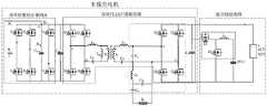
本发明第一方面提供了新能源汽车充电系统,包括无线电能传输装置和车载装置,所述车载装置包括输入单元、能量转换单元和动力电池,所述输入单元包括直流传输电路、交流传输电路和车载无线电能传输电路;所述能量转换单元包括依次连接的功率因数校正电路A、直流母线电容Cdc、双向CLLLC谐振变换器、维持电容Co、混合储能电路和动力电池,所述交流传输电路连接功率因数校正电路A,直流传输电路通过开关KD连接动力电池。A first aspect of the present invention provides a new energy vehicle charging system, including a wireless power transmission device and a vehicle-mounted device, the vehicle-mounted device includes an input unit, an energy conversion unit and a power battery, the input unit includes a DC transmission circuit, an AC transmission circuit and A vehicle-mounted wireless power transmission circuit; the energy conversion unit includes a power factor correction circuit A, a DC bus capacitor Cdc , a bidirectional CLLLC resonant converter, a maintenance capacitor Co , a hybrid energy storage circuit and a power battery connected in sequence, and the AC transmission The circuit is connected to the power factor correction circuit A, and the DC transmission circuit is connected to the power battery through the switch KD.
进一步的,所述功率因数校正电路A包括直流母线电容Cdc-s和结构相同且并联连接的第一桥臂、第二桥臂和第三桥臂,所述第一桥臂包括两个串联的场效应管,所述直流母线电容Cdc-s的两端并接在第二桥臂的两端,所述直流母线电容Cdc-s的与第二桥臂的连接点g之间设有开关K2。Further, the power factor correction circuit A includes a DC bus capacitor Cdc-s and a first bridge arm, a second bridge arm and a third bridge arm that have the same structure and are connected in parallel, and the first bridge arm includes two series-connected bridge arms. The two ends of the DC bus capacitor Cdc-s are connected to the two ends of the second bridge arm in parallel, and the connection point g between the DC bus capacitor Cdc-s and the second bridge arm is set There is switch K2 .
进一步的,所述交流传输电路包括单相交流传输和三相交流传输电路,所述单相交流传输电路包括端口a和零线端口N,三相交流传输电路包括端口b和端口c,端口a通过交流电感La连接第一桥臂的中点,端口b通过交流电感Lb连接第二桥臂的中点,端口c通过交流电感Lc连接第三桥臂的中点,所述零线端口N通过开关K1连接第二桥臂的中点,所述交流电感Lc与连接点g之间设有开关K3,所述连接点g与第三桥臂之间设有开关K4。Further, the AC transmission circuit includes a single-phase AC transmission circuit and a three-phase AC transmission circuit, the single-phase AC transmission circuit includes a port a and a neutral port N, and the three-phase AC transmission circuit includes a port b and a port c, and the port a The midpoint of the first bridge arm is connected through the AC inductance La, the portb is connected to the midpoint of the second bridge arm through the AC inductance Lb, and the portc is connected to the midpoint of the third bridge arm through the AC inductanceLc . The neutral line The port N is connected to the midpoint of the second bridge arm through the switch K1 , a switch K3 is arranged between the AC inductance Lc and the connection point g, and a switch K4 is arranged between the connection point g and the third bridge arm .
进一步的,所述双向CLLLC谐振变换器包括原边电路、变压器和副边电路,所述原边电路包括两个结构相同且并联连接的原边桥臂和原边线圈,所述原边线圈的两端分别连接两个原边桥臂的中点,所述副边电路包括两个结构相同且并联连接的副边桥臂和副边线圈,所述副边线圈的两端分别连接两个副边桥臂的中点,所述动力电池的两端并接在所述副边电路两端,维持电容Co的两端分别连接动力电池的正极和负极;Further, the bidirectional CLLLC resonant converter includes a primary side circuit, a transformer and a secondary side circuit. The primary side circuit includes two primary side bridge arms and a primary side coil with the same structure and connected in parallel. The two ends are respectively connected to the midpoints of the two primary bridge arms, the secondary circuit includes two secondary bridge arms and a secondary coil with the same structure and connected in parallel, and the two ends of the secondary coil are respectively connected to the two secondary The midpoint of the side bridge arm, the two ends of the power battery are connected to both ends of the secondary side circuit in parallel, and the two ends of the maintenance capacitor Co are respectively connected to the positive and negative electrodes of the power battery;
所述车载无线电能传输电路包括次级线圈和次级谐振电路,所述次级线圈通过开关KW并接在双向CLLLC谐振变换器的副边线圈的两端;The in-vehicle wireless power transmission circuit includes a secondary coil and a secondary resonance circuit, and the secondary coil is connected in parallel to both ends of the secondary coil of the bidirectional CLLLC resonant converter through a switch KW;
无线电能传输装置包括功率因数校正电路B、直流母线电容Cdc-w和若干并联的固定无线电能传输电路,所述固定无线电能传输电路包括初级线圈和初级功率电路。The wireless power transfer device includes a power factor correction circuit B, a DC bus capacitor Cdc-w , and several parallel fixed wireless power transfer circuits, the fixed wireless power transfer circuits including a primary coil and a primary power circuit.
进一步的,所述混合储能电路包括场效应管D1、场效应管D2、电感LD和超级电容Sc,场效应管D1的漏极连接动力电池的正极,场效应管D1的源极连接场效应管D2的漏极,场效应管D2的源极连接动力电池的负极,电感LD和超级电容Sc串联后并接在场效应管D2的漏极与源极之间。Further, the hybrid energy storage circuit includes a field effect transistor D1 , a field effect transistorD2 , an inductor LD and a super capacitor Sc , the drain of the field effect transistor D1 is connected to the positive electrode of the power battery, and the field effect transistor D1The source of the FET is connected to the drain of the FETD2 , the source of the FET D2 is connected to the negative electrode of the power battery, the inductor LD and the super capacitor Sc are connected in series and connected to the drain and source of the FETD2 between.
本发明另一方面提供了新能源汽车充电系统的工作方法,基于本发明第一方面所述的新能源汽车充电系统实现,包括充电模式,所述充电模式包括有线充电模式,所述有线充电模式包括单相交流充电模式,所述单相交流充电模式下,开关K1、开关K2和开关K3闭合,开关KD和开关K4断开,此时功率因数校正电路A为图腾柱功率因数校正电路级联升压电路,单相交流电压通过图腾柱功率因数校正电路后得到稳定的直流电压Udc-s,所述直流电压Udc-s经升压电路得到增大的直流电压Udc。Another aspect of the present invention provides a working method of a new energy vehicle charging system, which is implemented based on the new energy vehicle charging system described in the first aspect of the present invention, and includes a charging mode, the charging mode includes a wired charging mode, and the wired charging mode Including a single-phase AC charging mode, in the single-phase AC charging mode, the switch K1 , the switch K2 and the switch K3 are closed, the switch KD and the switch K4 are open, and the power factor correction circuit A is the totem pole power at this time. The factor correction circuit is cascaded with a booster circuit, and the single-phase AC voltage passes through the totem pole power factor correction circuit to obtain a stable DC voltage Udc-s , and the DC voltage Udc-s obtains an increased DC voltage U through the boost circuitdc .
进一步的,所述有线充电模式包括三相交流充电模式下,开关KD、开关K1、开关K2和开关K3断开,开关K4闭合,控制场效应管S1至场效应管S6,使输入电流和输入电压和相位相同。Further, the wired charging mode includes the three-phase AC charging mode, the switch KD , the switch K1 , the switch K2 and the switch K3 are turned off, the switch K4 is turned on, and the FET S1 to the FET S are controlled6 , so that the input current and input voltage and phase are the same.
进一步的,所述充电模式包括无线充电模式,所述无线模式充电模式下,电网电能经功率因数校正电路B和固定无线电能传输电路将电能传输至车载无线电能传输电路,使双向CLLLC谐振变换器的副边桥臂工作在整流状态,得到直流电为动力电池充电。Further, the charging mode includes a wireless charging mode. In the wireless charging mode, the grid power transfers the power to the vehicle-mounted wireless power transmission circuit through the power factor correction circuit B and the fixed wireless power transmission circuit, so that the bidirectional CLLLC resonant converter is used. The secondary side bridge arm works in the rectification state, and obtains direct current to charge the power battery.
进一步的,所述电能反馈模式包括有线电能反馈模式和无线电能反馈模式,Further, the power feedback mode includes a wired power feedback mode and a wireless power feedback mode,
所述有线电能反馈模式下,所述动力电池的电能通过双向CLLLC谐振变换器进行逆变整流得到高压直流电,使功率因数校正电路A工作在逆变状态得到与电网电压幅值和相位相同的交流电,经交流传输电路输出;In the wired electric energy feedback mode, the electric energy of the power battery is inverted and rectified by the bidirectional CLLLC resonant converter to obtain high-voltage direct current, so that the power factor correction circuit A works in the inverter state to obtain alternating current with the same amplitude and phase as the grid voltage. , output through the AC transmission circuit;
所述无线电能反馈模式下,所述动力电池的电能通过双向CLLLC谐振变换器的副边电路和初级功率电路进行逆变整流得到高压直流电;所述高压直流电经工作在逆变状态的功率因数校正电路B得到与电网电压幅值和相位相同的交流电。In the wireless energy feedback mode, the electric energy of the power battery is inverted and rectified by the secondary circuit and the primary power circuit of the bidirectional CLLLC resonant converter to obtain high-voltage direct current; the high-voltage direct current is corrected by the power factor of the inverter state. Circuit B receives alternating current with the same magnitude and phase as the grid voltage.
与现有技术相比,本发明具有如下效果:Compared with the prior art, the present invention has the following effects:
1、本专利提出一种新能源汽车充电系统,通过调节所述充电系统的各个开关的闭合或关断,使各单元的电路工作在不同的状态,不仅可以实现有线充电模式,还能实现无线充电模式,并且,有线充电模式还包括直流有线充电模式、单相交流充电模式和三相交流充电模式,满足不同场合的需求。1. This patent proposes a new energy vehicle charging system. By adjusting the closing or closing of each switch of the charging system, the circuits of each unit can work in different states, which can not only realize the wired charging mode, but also realize the wireless charging mode. Charging mode, and wired charging mode also includes DC wired charging mode, single-phase AC charging mode and three-phase AC charging mode to meet the needs of different occasions.
2、本发明的直流充电方式将电网380V三相交流电变为直流电后,经充电电缆直接对动力电池充电,由于其不受车内空间、重量、热量等条件的限制,其直流充电的输出功率最高可达400kW,大大提高了电动汽车充电效率,节省充电时间。2. The DC charging method of the present invention converts the 380V three-phase alternating current of the power grid into direct current, and then directly charges the power battery through the charging cable. Since it is not limited by conditions such as space, weight, and heat in the vehicle, the output power of the direct current charging can be reduced. Up to 400kW, which greatly improves the charging efficiency of electric vehicles and saves charging time.
3、本发明的交流充电方式时,系统工作于交流工作模式时,功率因数校正电路通过开关切换,电路拓扑变为图腾柱无桥功率因数校正电路级联升压电路或三相六开关式功率因数校正电路,使充电系统能够兼容单、三相交流电压输入,功率器件利用率高,能满足不同功率场合。3. In the AC charging mode of the present invention, when the system works in the AC working mode, the power factor correction circuit is switched by switches, and the circuit topology becomes a totem pole bridgeless power factor correction circuit cascade booster circuit or three-phase six-switch power The factor correction circuit makes the charging system compatible with single and three-phase AC voltage input, and the utilization rate of power devices is high, which can meet different power occasions.
4、当本发明的充电系统工作于无线充电模式时,通过线圈的磁场共振实现电能的无线传输,电动汽车无线充电过程中无需外接充电电缆,可适应多种恶劣环境和天气,避免漏电等安全隐患。4. When the charging system of the present invention works in the wireless charging mode, the wireless transmission of electric energy is realized through the magnetic field resonance of the coil, and there is no need for an external charging cable during the wireless charging of the electric vehicle, which can adapt to various harsh environments and weather, and avoid safety such as leakage. hidden danger.
5、本发明的充电系统能实现能量的多向流动,不仅能够将电能输入动力电池中完成充电过程,还能使动力电池的电能反馈得到交流电或直流电,满足电动汽车的不同需求。5. The charging system of the present invention can realize multi-directional flow of energy, not only can input electric energy into the power battery to complete the charging process, but also make the electric energy of the power battery feedback to obtain alternating current or direct current to meet the different needs of electric vehicles.
6、本发明包括混合储能方式,混合储能方式将超级电容与动力电池混合使用,能有效延长动力电池寿命,节约成本。6. The present invention includes a hybrid energy storage method. The hybrid energy storage method uses a super capacitor and a power battery in combination, which can effectively prolong the life of the power battery and save costs.
附图说明Description of drawings
图1为本发明具体实施例的新能源汽车充电系统的整体结构示意图;1 is a schematic diagram of the overall structure of a new energy vehicle charging system according to a specific embodiment of the present invention;
图2为本发明具体实施例的能量转换单元的电路原理图;2 is a schematic circuit diagram of an energy conversion unit according to a specific embodiment of the present invention;
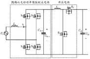
图3为本发明具体实施例的单相交流充电模式时功率因数校正电路A的电路原理图;3 is a circuit schematic diagram of a power factor correction circuit A in a single-phase AC charging mode according to a specific embodiment of the present invention;
图4为本发明具体实施例的图腾柱功率因数校正电路的模态图,图4a为正半周期的模态一的电路原理图,图4b为正半周期的模态二的电路原理图;4 is a modal diagram of a totem-pole power factor correction circuit according to a specific embodiment of the present invention, FIG. 4 a is a schematic circuit diagram of a mode 1 of a positive half cycle, and FIG. 4 b is a schematic circuit diagram of a mode 2 of the positive half cycle;
图5为本发明具体实施例的升压电路模态图,图5a为开关S2导通模态的电路原理图,图5b为开关S2关断模态的电路原理图;FIG. 5 is a modal diagram of a booster circuit according to a specific embodiment of the present invention, FIG. 5 a is a schematic circuit diagram of a switch S2 on mode, and FIG. 5 b is a circuit schematic diagram of a switch S2 off mode;
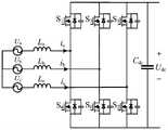
图6为本发明具体实施例的三相交流充电模式时功率因数校正电路A的电路原理图;6 is a circuit schematic diagram of a power factor correction circuit A in a three-phase AC charging mode according to a specific embodiment of the present invention;
图7为本发明具体实施例的无线电能传输装置的电路原理图。FIG. 7 is a schematic circuit diagram of a wireless power transmission device according to a specific embodiment of the present invention.
具体实施方式Detailed ways
以下通过特定的具体实例说明本发明的实施方式,本领域技术人员可由本说明书所揭露的内容轻易地了解本发明的其他优点与功效。本发明还可以通过另外不同的具体实施方式加以实施或应用,本说明书中的各项细节也可以基于不同观点与应用,在没有背离本发明的精神下进行各种修饰或改变。需说明的是,在不冲突的情况下,以下实施例及实施例中的特征可以相互组合。The embodiments of the present invention are described below through specific specific examples, and those skilled in the art can easily understand other advantages and effects of the present invention from the contents disclosed in this specification. The present invention can also be implemented or applied through other different specific embodiments, and various details in this specification can also be modified or changed based on different viewpoints and applications without departing from the spirit of the present invention. It should be noted that the following embodiments and features in the embodiments may be combined with each other under the condition of no conflict.
需要说明的是,以下实施例中所提供的图示仅以示意方式说明本发明的基本构想,遂图示中仅显示与本发明中有关的组件而非按照实际实施时的组件数目、形状及尺寸绘制,其实际实施时各组件的型态、数量及比例可为一种随意的改变,且其组件布局型态也可能更为复杂。It should be noted that the diagrams provided in the following embodiments are only to illustrate the basic concept of the present invention in a schematic way, so the diagrams only show the components related to the present invention rather than the number, shape and number of components in actual implementation. For dimension drawing, the type, quantity and proportion of each component can be arbitrarily changed in actual implementation, and the component layout may also be more complicated.
如图1所示,本发明第一方面提供了新能源汽车充电系统,包括车载装置和无线电能传输装置,所述车载装置包括输入单元、能量转换单元和动力电池;As shown in FIG. 1 , a first aspect of the present invention provides a new energy vehicle charging system, including a vehicle-mounted device and a wireless power transmission device, the vehicle-mounted device including an input unit, an energy conversion unit and a power battery;
所述输入单元包括直流传输电路、交流传输电路、车载无线电能传输电路和光伏充电电路,所述光伏充电电路包括光伏板和MPPT(最大功率跟踪点)电路;所述交流传输电路包括单相交流传输电路和三相交流传输电路,单相交流充电作为传统的充电方式,三相交流充电方式可以为系统提供功率角度较大的充电功率,直流充电可以不受新能源汽车的空间、重量、热量条件的限制,光伏充电电路作为辅助电源为动力电池提供电能,多种电能输入方式满足新能源汽车的不同充电需求。The input unit includes a DC transmission circuit, an AC transmission circuit, a vehicle-mounted wireless power transmission circuit and a photovoltaic charging circuit, the photovoltaic charging circuit includes a photovoltaic panel and an MPPT (maximum power tracking point) circuit; the AC transmission circuit includes a single-phase AC Transmission circuit and three-phase AC transmission circuit, single-phase AC charging as a traditional charging method, three-phase AC charging method can provide charging power with a larger power angle for the system, and DC charging can be free from the space, weight, and heat of new energy vehicles. Due to the limitation of conditions, the photovoltaic charging circuit acts as an auxiliary power source to provide power for the power battery, and a variety of power input methods meet the different charging needs of new energy vehicles.
如图2所示,所述能量转换单元包括依次连接的功率因数校正电路A、直流母线电容Cdc、双向CLLLC谐振变换器、维持电容Co、混合储能电路和动力电池,所述交流传输电路连接功率因数校正电路A,直流传输电路通过开关KD连接动力电池,所述光伏充电电路连接动力电池,As shown in FIG. 2 , the energy conversion unit includes a power factor correction circuit A, a DC bus capacitor Cdc , a bidirectional CLLLC resonant converter, a maintenance capacitor Co , a hybrid energy storage circuit and a power battery, which are connected in sequence. The circuit is connected to the power factor correction circuit A, the DC transmission circuit is connected to the power battery through the switch KD , and the photovoltaic charging circuit is connected to the power battery,
所述功率因数校正电路A,用以根据输入电压类型通过各开关切换变为单相功率因数校正电路或三相功率因数校正电路;如图所示,所述功率因数校正电路A包括直流母线电容Cdc-s和结构相同且并联连接的第一桥臂、第二桥臂和第三桥臂,每个桥臂包括两个串联的碳化硅场效应管,所述第一桥臂包括串联的场效应管S1和场效应管S4,所述第二桥臂包括串联的场效应管S3和场效应管S6,第三桥臂包括串联的场效应管S5和场效应管S2,所述直流母线电容Cdc-s的两端并接在第二桥臂的两端,所述直流母线电容Cdc-s的与第二桥臂的连接点g之间设有开关K2。The power factor correction circuit A is used to switch to a single-phase power factor correction circuit or a three-phase power factor correction circuit by switching each switch according to the type of input voltage; as shown in the figure, the power factor correction circuit A includes a DC bus capacitor Cdc-s and a first bridge arm, a second bridge arm and a third bridge arm that have the same structure and are connected in parallel, each bridge arm includes two series-connected SiC field effect transistors, and the first bridge arm includes series-connected silicon carbide field effect transistors Field effect transistor S1 and field effect transistor S4 , the second bridge arm includes field effect transistor S3 and field effect transistor S6 connected in series, and the third bridge arm includes field effect transistor S5 and field effect transistor S connected in series2. Both ends of the DC bus capacitor Cdc-s are connected in parallel with both ends of the second bridge arm, and a switch K is provided between the DC bus capacitor Cdc-s and the connection point g of the second bridge arm2 .
所述交流传输电路包括单相交流传输和三相交流传输电路,所述单相交流传输电路包括端口a和零线端口N,三相交流传输电路包括端口b和端口c,端口a通过交流电感La连接第一桥臂的中点,端口b通过交流电感Lb连接第二桥臂的中点,端口c通过交流电感Lc连接第三桥臂的中点,所述零线端口N通过开关K1连接第二桥臂的中点,所述交流电感Lc与连接点g之间设有开关K3,所述连接点g与第三桥臂之间设有开关K4,所述直流母线电容Cdc的两端分别连接第三桥臂的两端;由功率因数校正电路A输出的高压直流电通过直流母线电容Cdc为后级电路提供一个稳定且低纹波的直流母线电压。The AC transmission circuit includes a single-phase AC transmission circuit and a three-phase AC transmission circuit. The single-phase AC transmission circuit includes a port a and a neutral port N. The three-phase AC transmission circuit includes a port b and a port c. The port a passes through an AC inductor. La is connected to the midpoint of the first bridge arm, portb is connected to the midpoint of the second bridge arm through the AC inductance Lb, portc is connected to the midpoint of the third bridge arm through the AC inductanceLc , and the neutral port N passes through The switch K1 is connected to the midpoint of the second bridge arm, a switch K3 is arranged between the AC inductance Lc and the connection point g, a switch K4 is arranged between the connection point g and the third bridge arm, the The two ends of the DC bus capacitor Cdc are respectively connected to the two ends of the third bridge arm; the high voltage DC output by the power factor correction circuit A provides a stable and low ripple DC bus voltage for the subsequent circuit through the DC bus capacitor Cdc .
所述双向CLLLC谐振变换器包括原边电路、变压器T和副边电路,所述原边电路包括两个结构相同且并联连接的原边桥臂、原边谐振电路和原边线圈np,如图所示,场效应管Q1和场效应管Q3串联构成Q1-Q3桥臂,场效应管Q2和场效应管Q4构成Q2-Q4桥臂,所述原边谐振电路包括谐振电感Lr1、励磁电感Lm和谐振电容Cr1,所述谐振电感Lr1的一端连接Q1-Q3桥臂的中点a,谐振电感Lr1的另一端连接原边线圈np的一端,谐振电容Cr1的一端连接Q2-Q4桥臂的中点b,谐振电容Cr1的另一端连接原边线圈np的另一端;所述副边电路包括两个结构相同且并联连接的副边桥臂、副边谐振电路和副边线圈ns,场效应管Q5和场效应管Q7串联构成Q5-Q7桥臂,场效应管Q6和场效应管Q8构成Q6-Q8桥臂,所述副边谐振电路包括谐振电感Lr2和谐振电容Cr2,所述谐振电感Lr2的一端连接Q5-Q7桥臂的中点c,谐振电感Lr2的另一端连接副边线圈ns的一端,谐振电容Cr2的一端连接Q6-Q8桥臂的中点d,谐振电容Cr2的另一端连接原边线圈ns的另一端,所述原边电路和副边电路的谐振元件参数值对应相同,用以实现电路的对称性,进而实现电能的双向传输;所述动力电池的两端并接在所述副边电路两端,维持电容Co的两端分别连接动力电池的正极和负极。The bidirectional CLLLC resonant converter includes a primary side circuit, a transformer T and a secondary side circuit, and the primary side circuit includes two primary side bridge arms with the same structure and connected in parallel, a primary side resonant circuit and a primary side coil np , such as As shown in the figure, the FET Q1 and the FET Q3 are connected in series to form the Q1 -Q3 bridge arm, the FET Q2 and the FET Q4 form the Q2 -Q4 bridge arm, and the primary side resonates The circuit includes a resonant inductance Lr1 , an excitation inductance Lm and a resonant capacitor Cr1 , one end of the resonant inductance Lr1 is connected to the midpoint a of the bridge arms of Q1 -Q3 , and the other end of the resonant inductance Lr1 is connected to the primary coil n One end ofp , one end of the resonant capacitor Cr1 is connected to the midpoint b of the Q2 -Q4 bridge arm, and the other end of the resonant capacitor Cr1 is connected to the other end of the primary coil np ; the secondary circuit includes two identical structures. And the secondary side bridge arm, the secondary side resonant circuit and the secondary side coilns connected in parallel, the field effect transistorQ5 and the field effect transistorQ7 are connected in series to form theQ5- Q7 bridge arm, the field effect transistorQ6 and the field effect transistor Q8 constitutes the Q6 -Q8 bridge arm, the secondary side resonant circuit includes a resonant inductance Lr2 and a resonant capacitor Cr2 , one end of the resonant inductance Lr2 is connected to the midpoint c of the Q5 -Q7 bridge arm, and the resonance The other end of the inductor Lr2 is connected to one end of the secondary coilns , one end of the resonant capacitor Cr2 is connected to the midpoint d of theQ6 -Q8 bridge arm, and the other end of the resonant capacitor Cr2 is connected to the other end of the primary coilns , the resonant element parameter values of the primary side circuit and the secondary side circuit correspond to the same, in order to realize the symmetry of the circuit, and then realize the bidirectional transmission of electric energy; the two ends of the power battery are connected to both ends of the secondary side circuit in parallel , the two ends of the maintenance capacitor Co are respectively connected to the positive and negative electrodes of the power battery.
所述车载无线电能传输电路包括次级线圈Rx和次级谐振电路,所述次级谐振电路包括谐振电感LR、谐振电容CR1和谐振电容CR,所述谐振电容CR的一端连接次级线圈Rx的一端,谐振电容CR的另一端连接谐振电感LR的一端,谐振电感LR的另一端通过开关KW连接Q5-Q7桥臂中点c,次级线圈RX的另一端连接Q6-Q8桥臂的中点d,所述谐振电容CR1一端接在谐振电感LR与谐振电容CR之间,另一端连接桥臂Q6-Q8桥臂的中点d。The in-vehicle wireless power transmission circuit includes a secondary coilRx and a secondary resonance circuit, the secondary resonance circuit includes a resonance inductorLR , a resonance capacitorCR1 and a resonance capacitorCR , and one end of the resonance capacitorCR is connected to One end of the secondary coilRx , the other end of the resonant capacitor CRis connected to one end of the resonant inductanceLR , and the other end of the resonant inductanceLR is connected to the midpoint c of the bridge arms ofQ5- Q7 through the switchKW , and the secondary coil R The other end ofX is connected to the midpoint d of the bridge armsQ6 -Q8 , one end of the resonant capacitorCR1 is connected between the resonant inductorLR and the resonant capacitorCR , and the other end is connected to the bridge armsQ6 -Q8 bridge arms the midpoint d.
所述无线电能传输装置固定在地下,如图7所示,无线电能传输装置包括功率因数校正电路B、直流母线电容Cdc-w和若干并联的固定无线电能传输电路,如图所示,所述功率因数校正电路B包括三个结构相同且并联连接的桥臂和直流母线电容Cdc-w,串联连接的场效应管T1和场效应管T4构成T1-T4桥臂,串联连接的场效应管T3和场效应管T6构成T3-T6桥臂,串联连接的场效应管T5和场效应管T2构成T5-T2桥臂,所述直流母线电容Cdc-W的两端并接在T5-T2桥臂的两端。The wireless power transmission device is fixed underground, as shown in Figure 7, the wireless power transmission device includes a power factor correction circuit B, a DC bus capacitor Cdc-w and several parallel fixed wireless power transmission circuits, as shown in the figure, theThe power factor correction circuit B includesthree bridge arms and DC bus capacitors C dc-w with the same structure and connected in parallel.The connected field effect transistor T3 and the field effect transistorT6 form the T3-T6 bridge arm, the serially connected field effect transistor T5 and the field effect transistorT2 form theT5-T2 bridge arm, and the DC bus capacitor Both ends of Cdc-W are connected in parallel at both ends of the T5 -T2 bridge arms.
所述固定无线电能传输电路包括初级线圈TX、初级功率电路和补偿谐振电路,所述初级功率电路包括两个结构相同且并联连接的桥臂,场效应管Q9和场效应管Q11串联构成Q9-Q11桥臂,场效应管Q10和场效应管Q12串联构成Q10-Q12桥臂;The fixed wireless power transmission circuit includes a primary coil TX , a primary power circuit and a compensation resonance circuit. The primary power circuit includes two bridge arms with the same structure and connected in parallel. The field effect transistor Q9 and the field effect transistor Q11 are connected in series to form Q.9 -Q11 bridge arm, FET Q10 and FET Q12 are connected in series to form a Q10 -Q12 bridge arm;
所述补偿谐振电路包括谐振电感LT1、谐振电容CT1和谐振电容CT,谐振电感LT1的一端连接Q9-Q11桥臂的中点e谐振电感的LT1的另一端通过谐振电容CT连接初级线圈Tx的一端,所述初级线圈Tx的另一端连接Q10-Q12桥臂的中点f,,所述谐振电容CT1的一端接在谐振电感LT1与谐振电容CT之间,另一端连接Q10-Q12桥臂中点f。The compensation resonant circuit includes a resonant inductance LT1 , a resonant capacitor CT1 and a resonant capacitor CT , one end of the resonant inductance LT1 is connected to the midpoint of the Q9 -Q11 bridge arm, and the other end of the resonant inductor LT1 passes through the resonant capacitor. CT is connected to one end of the primary coil Tx , the other end of the primary coil Tx is connected to the midpoint f of the Q10-Q12 bridge arm, andone end of the resonant capacitor CT1 is connected to the resonant inductor LT1 and the resonant capacitor Between C andT , the other end is connected to the midpoint f of the bridge arms of Q10 -Q12 .
所述混合储能电路能有效延长动力电池寿命,包括场效应管D1、场效应管D2、电感LD和超级电容Sc,场效应管D1、场效应管D2、电感LD构成双向直流/直流电路,场效应管D1的漏极连接动力电池的正极,场效应管D1的源极连接场效应管D2的漏极,场效应管D2的源极连接动力电池的负极,电感LD和超级电容Sc串联后并接在场效应管D2的漏极与源极之间。The hybrid energy storage circuit can effectively prolong the life of the power battery, including FET D1 , FET D2 , inductor LD and super capacitor Sc , FETD1 , FETD2 , inductor LDA bidirectional DC/DC circuit is formed, the drainof the FET D1 is connected to the positive electrode of the power battery, the sourceof the FET D1 is connected to the drain of the FETD2 , and the source of the FET D2 is connected to the power battery The negative pole of the inductance LD and the super capacitor Sc are connected in series between the drain and the source of the field effect transistor D2 .
基于上述新能源汽车充电系统,其工作方法包括:充电模式,电能反馈模式和混合储能模式。Based on the above-mentioned new energy vehicle charging system, its working method includes: charging mode, electric energy feedback mode and hybrid energy storage mode.
充电模式是充电系统的主要工作过程,基于上述充电系统,所述充电模式分为有线充电模式和无线充电模式,根据电能的来源不同,所述有线充电模式包括单相充电模式、三相充电模式和直流充电模式,在有线充电模式下,开关Kw断开;The charging mode is the main working process of the charging system. Based on the above charging system, the charging mode is divided into a wired charging mode and a wireless charging mode. According to different sources of electrical energy, the wired charging mode includes a single-phase charging mode and a three-phase charging mode. and DC charging mode, in wired charging mode, switch Kw is disconnected;
所述单相交流充电模式下,开关K1、开关K2和开关K3闭合,开关KD和开关K4断开,此时功率因数校正电路A为图腾柱功率因数校正电路级联升压电路,具体如图3所示,图腾柱功率因数校正电路将单相220V交流电压转换成为直流电压Udc-s,其额定值为400V,通过级联的升压电路,使后级谐振变换器分别在单相、三相输入模式下的输入电压为同一值,将400V的直流电压Udc-s升至700V直流电压Udc。In the single-phase AC charging mode, the switch K1 , the switch K2 and the switch K3 are closed, and the switch KD and the switch K4 are disconnected. At this time, the power factor correction circuit A is a totem-pole power factor correction circuit cascade boosting. The circuit, as shown in Figure 3, the totem-pole power factor correction circuit converts the single-
当图腾柱功率因数校正电路处于稳态工作时,一个电源周期可分为四个模态,正半周期的两个工作模态和负半周期的两个工作模态类似,以交流输入电源正半周期的两个模态为例。When the totem pole power factor correction circuit is working in a steady state, one power cycle can be divided into four modes, the two working modes of the positive half cycle and the two working modes of the negative half cycle are similar. Take two modes of a half cycle as an example.
工作模态一时,场效应管S1和场效应管S3关断,场效应管S4和场效应管S6导通,单相电压Ua通过电感La、场效应管S4和场效应管S6的回路对电感La进行充电,直流母线电容Cdc-s对后级电路进行放电;When the working mode isone , the FET S1 and the FET S3 are turned off, the FET S4 and the FETS6 are turned on, and the single-phase voltage Ua passes through the inductor La , the FET S4 and the field effect transistor S6. The loop of the effect tubeS6 charges the inductorLa , and the DC bus capacitor Cdc-s discharges the subsequent circuit;
工作模态二时,场效应管S3和场效应管S4关断,场效应管S1和场效应管S6导通,单相电压Ua和电感La通过场效应管S1和场效应管S6回路对直流母线电容Cdc-s进行充电,此时电感La处于放电状态。In the second working mode, the FET S3 and the FET S4 are turned off, the FET S1 and the FETS6 are turnedon , and thesingle -phase voltage Ua and the inductance Lapass through the FET S1 and The FETS6 loop charges the DC bus capacitor Cdc-s , and the inductor La is ina discharge state at this time.
所述升压电路处于稳态工作时,分为两个工作模态,模态一,场效应管S2导通时,直流电压Udc-s对电感Lc充电;模态二,场效应管S2关断时,直流电压Udc-s和电感Lc通过场效应管S5回路对直流母线电容Cdc进行充电,此时电感Lc处于放电状态。When the boost circuit is working in a steady state, it is divided intotwo working modes, mode one, when the field effect transistor S2 is turned on, the direct current voltage Udc-s charges the inductor Lc ; mode two, the field effect When the tube S2 is turned off, the DC voltage Udc-sand the inductor Lc charge the DC bus capacitor Cdc through the FET S5 loop, and the inductor Lc is in a discharge state at this time.
所述三相交流充电模式下,开关KD、开关K1、开关K2和开关K3断开,开关K4闭合,此时的功率因数校正电路A为三相六开关式功率因数校正电路,功能上实现三个PWM(脉冲宽度调制)整流器,Ua、Ub、Uc为三相输入电网电压,此时交流电感La=Lb=Lc,如图6所示,在充电过程中,通过控制碳化硅场效应管S1至场效应管S6六个场效应管的通断,使得输入电流与输入电压同相位,波形近似于正弦波,达到功率因数校正目的。In the three-phase AC charging mode, the switch KD , the switch K1 , the switch K2 and the switch K3 are disconnected, and the switch K4 is closed, and the power factor correction circuit A at this time is a three-phase six-switch type power factor correction circuit. , functionally realize three PWM (pulse width modulation) rectifiers, Ua , Ub , Uc are the three-phase input grid voltage, at this time the AC inductance La =Lb =Lc , as shown in Figure 6, when charging In the process, by controlling the on-off of six MOSFETs from SiC FET S1 to FET S6 , the input current and the input voltage are in the same phase, and the waveform is similar to a sine wave, so as to achieve the purpose of power factor correction.
所述无线模式充电模式下,开关Kw闭合,电网电能经功率因数校正电路B和固定无线电能传输电路将电能传输至车载无线电能传输电路,使双向CLLLC谐振变换器的副边桥臂工作在整流状态,得到直流电为动力电池充电;电网经功率因数校正电路B整流,并经直流母线电容Cdc-w滤波后为后级电路提供稳定的直流电源。将初级线圈TX与次级线圈RX调整至相同的频率,用以实现能量交换。Q9-Q11桥臂和Q10-Q12桥臂构成高频逆变器,将直流电转换为高频交流电压供给由谐振电感LT、谐振电容CT、谐振电容CT1组成的LCC补偿谐振电路,补偿谐振电路为次级线圈Rx提供高频高压的激励,电能从初级线圈TX传输至次级线圈Rx,次级线圈Rx侧的补偿谐振电路将接收到的电能变换为所需的输出电压后通过场效应管Q5-Q7桥臂和Q6-Q8桥臂整流,将高频交流电转换为直流电为动力电池供电。In the wireless mode charging mode, the switchKw is closed, and the grid power is transmitted to the vehicle-mounted wireless power transmission circuit through the power factor correction circuit B and the fixed wireless power transmission circuit, so that the secondary side bridge arm of the bidirectional CLLLC resonant converter works at In the rectification state, direct current is obtained to charge the power battery; the power grid is rectified by the power factor correction circuit B, and filtered by the DC bus capacitor Cdc-w to provide a stable DC power supply for the subsequent circuit. The primary coilTX and the secondary coilRX are adjusted to the same frequency to achieve energy exchange. Q9 -Q11 bridge arm and Q10 -Q12 bridge arm constitute a high frequency inverter, which converts direct current into high frequency alternating voltage and supplies LCC compensation composed of resonant inductor LT , resonant capacitor CT and resonant capacitor CT1 Resonant circuit, the compensation resonant circuit provides high frequency and high voltage excitation for the secondary coil Rx, the electric energyis transmitted from the primary coil T Xto the secondary coilRx , and the compensation resonant circuit on the side of the secondary coil Rx converts the received electric energy into all The required output voltage is rectified by theQ5- Q7 bridge arms andQ6 -Q8 bridge arms of the field effect transistors, and the high-frequency alternating current is converted into direct current to supply power for the power battery.
所述电能反馈模式包括并网模式和直流电能反馈模式,所述并网模式将动力电池中的电能反馈至电网,所述直流电能反馈模式用以降动力电池中的电能转化为高压直流电,用以实现为其他动力电池充电等功能。The power feedback mode includes a grid-connected mode and a DC power feedback mode, the grid-connected mode feeds back the power in the power battery to the power grid, and the DC power feedback mode is used to reduce the power in the power battery. Realize functions such as charging other power batteries.
所述并网模式包括有线并网模式和无线并网模式,所述有线并网模式下,所述CLLLC谐振变换器中变压器原、副两侧谐振元件参数值对应相同,保证了电路的对称性,能实现能量的双向流动,使得动力电池中的能量可回馈至电网。所述Q1-Q3桥臂和Q2-Q4桥臂构成原边全桥变换器,Q5-Q7桥臂和Q6-Q8桥臂构成副边全桥变换器,此时励磁电感Lm等效到变压器T的副边侧,控制场效应管Q5、Q6、Q7、Q8的驱动信号,实现逆变功能;此时场效应管Q1、Q2、Q3、Q4不加驱动信号,而是采用场效应管反并联的二极管进行整流,所述功率因数校正电路A工作于逆变状态,将高压直流电逆变为与电网同幅值、同相位的交流电,向电网侧反馈能量;The grid-connected mode includes a wired grid-connected mode and a wireless grid-connected mode. In the wired grid-connected mode, the parameter values of the resonant elements on the primary and secondary sides of the transformer in the CLLLC resonant converter correspond to the same, ensuring the symmetry of the circuit. , can realize the two-way flow of energy, so that the energy in the power battery can be fed back to the grid. The Q1 -Q3 bridge arms and the Q2 -Q4 bridge arms constitute the primary side full-bridge converter, and the Q5 -Q7 bridge arms and the Q6 -Q8 bridge arms constitute the secondary side full bridge converter. The excitation inductance Lm is equivalent to the secondary side of the transformer T, and controls the driving signals of the field effect transistors Q5 , Q6 , Q7 , and Q8 to realize the inverter function; at this time, the field effect transistors Q1 , Q2 , Q3.Q4 does not add a drive signal, but uses an anti-parallel diode of a field effect transistor for rectification. The power factor correction circuit A works in an inversion state, and inverts the high-voltage direct current to the same amplitude and same phase as the power grid. Alternating current, feedback energy to the grid side;
在无线并网模式下,车载电能传输电路和固定电能传输电路两侧的LCC补偿谐振网络谐振元件参数值对应相同,保证了电路的对称性,能实现能量的双向流动,使得动力电池中的能量可回馈至电网。此时改变场效应管Q5、Q6、Q7、Q8的驱动信号,实现逆变功能;场效应管Q9、Q10、Q11、Q12不加驱动信号,采用场效应管反并联的二极管进行整流,功率因数校正电路B工作于逆变状态,将高压直流电逆变为与电网同幅值、同相位的交流电,向电网侧反馈能量。In the wireless grid-connected mode, the parameter values of the LCC compensation resonant network resonant elements on both sides of the on-board power transmission circuit and the fixed power transmission circuit correspond to the same value, which ensures the symmetry of the circuit and realizes the bidirectional flow of energy, which makes the energy in the power battery Can be fed back to the grid.At this time, the driving signalsof theFETs Q5 , Q6 , Q7 , and Q8 are changed to realize the inverter function; The diodes connected in parallel are used for rectification, and the power factor correction circuit B works in the inverter state, inverting the high-voltage direct current into alternating current with the same amplitude and phase as the grid, and feeding back energy to the grid side.
所述直流反馈模式包括无线直流反馈模式和有线直流反馈模式,当电网断电无法提供能量时,若此时多辆电动汽车与直流母线接口连接,系统可实现车-车之间能量的无线传递。The DC feedback mode includes a wireless DC feedback mode and a wired DC feedback mode. When the power grid fails to provide energy, if multiple electric vehicles are connected to the DC bus interface at this time, the system can realize the wireless transmission of energy between vehicles. .
所述无线直流反馈模式下,如图1所示,控制场效应管Q5、Q6、Q7、Q8的驱动信号将电动汽车1中动力电池的直流电逆变为高频脉冲信号,通过次级线圈和初级线圈将传输至次级功率电路1,对场效应管Q9、Q10、Q11、Q12的反并联的二极管进行整流,整流后的直流母线电压,为与直流母线接口连接的电动汽车N提供高压直流电。In the wireless DC feedback mode, as shown in FIG. 1 , the driving signals of the control field effect transistors Q5 , Q6 , Q7 , and Q8 are used to invert the DC power of the power battery in the electric vehicle 1 into a high-frequency pulse signal. The secondary coil and the primary coil will be transmitted to the secondary power circuit 1 to rectify the anti-parallel diodes of the field effect transistors Q9 , Q10 , Q11 , and Q12 , and the rectified DC bus voltage is used to interface with the DC bus The connected electric vehicle N provides high-voltage direct current.
在有线直流反馈模式下,控制场效应管Q5、Q6、Q7、Q8的驱动信号将电动汽车1中动力电池的直流电逆变为高频脉冲信号,通过变压器将电能传输至功双向CLLLC谐振变换器,对场效应管Q1、Q2、Q3、Q4反并联的二极管进行整流,得到高压直流电为电动汽车N充电。In the wired DC feedback mode, the driving signals of the control field effect transistors Q5 , Q6 , Q7 , and Q8 invert the DC power of the power battery in the electric vehicle 1 into a high-frequency pulse signal, and transmit the power to the power bidirectionally through the transformer. The CLLLC resonant converter rectifies the anti-parallel diodes of the field effect transistors Q1 , Q2 , Q3 and Q4 to obtain high-voltage direct current to charge the electric vehicle N.
当电动汽车突然加速、制动或爬坡时易对动力电池造成损坏,缩短电池寿命,因此本发明增加了所述混合储能模式,利用超级电容能量密度小,功率密度大的特点,实现快速的充放电,为车辆启停瞬间提供高倍率电流进行充放电。当电动汽车行驶时,光伏供电电路作为辅助电源及时对超级电容储能,将超级电容与场效应管D1、场效应管D2、电感LD构成双向直流/直流电路串联后,与动力电池并联,当电动汽车启动或加速时,双向直流/直流电路工作在升压状态,由超级电容输出能量。当电动汽车制动时,双向直流/直流电路工作在降压状态,超级电容可回收制动能量。即根据电动汽车的行驶状态,使双向直流/直流电路工作在降压、升压模式,以实现对超级电容的充放电。通过混合储能方式,可以延长动力电池寿命,降低成本。When an electric vehicle suddenly accelerates, brakes or climbs a slope, it is easy to damage the power battery and shorten the battery life. Therefore, the present invention adds the hybrid energy storage mode, and utilizes the characteristics of low energy density and high power density of the super capacitor to achieve rapid It provides high-rate current for charging and discharging at the moment of starting and stopping of the vehicle. When the electric vehicle is running, the photovoltaic power supply circuit acts as an auxiliary power supply to store energy in the super capacitor in time. After the super capacitor is connected with the field effect transistor D1 , the field effect transistorD2 and the inductor LD to form a bidirectional DC/DC circuit in series, it is connected with the power battery. In parallel, when the electric vehicle starts or accelerates, the bidirectional DC/DC circuit works in a boosted state, and the supercapacitor outputs energy. When the electric vehicle brakes, the bidirectional DC/DC circuit works in a step-down state, and the supercapacitor can recover the braking energy. That is, according to the driving state of the electric vehicle, the bidirectional DC/DC circuit is made to work in the buck and boost modes to realize the charging and discharging of the super capacitor. Through the hybrid energy storage method, the life of the power battery can be extended and the cost can be reduced.
综上,本发明的新能源汽车充电系统,能够兼容交流充电、直流充电和无线充电多种充电方式,以适应不同场合的使用,使电动汽车灵活充电。其中交流充电方式又能兼容单相220V电压与三相380V电压的输入,充电机内功率器件利用率高,同时满足于不同功率场合。无线充电方式将电路及线圈嵌于地下并自动接入电网,能实现同时为多辆电动汽车充电的功能。通过超级电容与动力电池的混合使用,使得电动汽车储能系统具备高能量和高功率密度,延长动力电池的使用寿命。综上所述,该新能源汽车充电系统具有较好的应用前景。To sum up, the new energy vehicle charging system of the present invention can be compatible with various charging modes of AC charging, DC charging and wireless charging, so as to adapt to different occasions and make the electric vehicle charge flexibly. Among them, the AC charging mode can be compatible with the input of single-
上述实施例仅例示性说明本发明的原理及其功效,而非用于限制本发明。任何熟悉此技术的人士皆可在不违背本发明的精神及范畴下,对上述实施例进行修饰或改变。因此,举凡所属技术领域中具有通常知识者在未脱离本发明所揭示的精神与技术思想下所完成的一切等效修饰或改变,仍应由本发明的权利要求所涵盖。The above-mentioned embodiments merely illustrate the principles and effects of the present invention, but are not intended to limit the present invention. Anyone skilled in the art can make modifications or changes to the above embodiments without departing from the spirit and scope of the present invention. Therefore, all equivalent modifications or changes made by those with ordinary knowledge in the technical field without departing from the spirit and technical idea disclosed in the present invention should still be covered by the claims of the present invention.
Claims (9)
Priority Applications (1)
| Application Number | Priority Date | Filing Date | Title |
|---|---|---|---|
| CN202210112080.4ACN114465336A (en) | 2022-01-28 | 2022-01-28 | New energy automobile charging system and working method thereof |
Applications Claiming Priority (1)
| Application Number | Priority Date | Filing Date | Title |
|---|---|---|---|
| CN202210112080.4ACN114465336A (en) | 2022-01-28 | 2022-01-28 | New energy automobile charging system and working method thereof |
Publications (1)
| Publication Number | Publication Date |
|---|---|
| CN114465336Atrue CN114465336A (en) | 2022-05-10 |
Family
ID=81410862
Family Applications (1)
| Application Number | Title | Priority Date | Filing Date |
|---|---|---|---|
| CN202210112080.4APendingCN114465336A (en) | 2022-01-28 | 2022-01-28 | New energy automobile charging system and working method thereof |
Country Status (1)
| Country | Link |
|---|---|
| CN (1) | CN114465336A (en) |
Cited By (3)
| Publication number | Priority date | Publication date | Assignee | Title |
|---|---|---|---|---|
| CN115296432A (en)* | 2022-05-19 | 2022-11-04 | 湖州晟威新能源科技有限公司 | Wireless charging, electric driving and feedback power grid integrated system for electric automobile |
| CN116714464A (en)* | 2023-04-20 | 2023-09-08 | 优跑汽车技术(上海)有限公司 | Charging control method, device, equipment and storage medium for electric vehicles |
| CN120127800A (en)* | 2025-03-19 | 2025-06-10 | 山东省产品质量检验研究院 | A smart photovoltaic storage charging and testing energy collaborative optimization control method and system |
Citations (3)
| Publication number | Priority date | Publication date | Assignee | Title |
|---|---|---|---|---|
| CN103904671A (en)* | 2014-03-13 | 2014-07-02 | 西安理工大学 | V2G-based single-phase micro-grid voltage regulating system and control method thereof |
| CN111478573A (en)* | 2020-04-16 | 2020-07-31 | 深圳威迈斯新能源股份有限公司 | Power factor adjusting framework suitable for single-phase and three-phase power grid and control method thereof |
| CN113972720A (en)* | 2021-10-29 | 2022-01-25 | 哈尔滨理工大学 | A DC input electric vehicle charging system |
- 2022
- 2022-01-28CNCN202210112080.4Apatent/CN114465336A/enactivePending
Patent Citations (3)
| Publication number | Priority date | Publication date | Assignee | Title |
|---|---|---|---|---|
| CN103904671A (en)* | 2014-03-13 | 2014-07-02 | 西安理工大学 | V2G-based single-phase micro-grid voltage regulating system and control method thereof |
| CN111478573A (en)* | 2020-04-16 | 2020-07-31 | 深圳威迈斯新能源股份有限公司 | Power factor adjusting framework suitable for single-phase and three-phase power grid and control method thereof |
| CN113972720A (en)* | 2021-10-29 | 2022-01-25 | 哈尔滨理工大学 | A DC input electric vehicle charging system |
Non-Patent Citations (1)
| Title |
|---|
| ALIREZA KHALIGH等: "Global Trends in High-Power On-Board Chargers for Electric Vehicles", IEEE TRANSACTIONS ON VEHICULAR TECHNOLOGY, vol. 68, no. 4, 16 April 2019 (2019-04-16), pages 3306 - 3324, XP011719667, DOI: 10.1109/TVT.2019.2897050* |
Cited By (4)
| Publication number | Priority date | Publication date | Assignee | Title |
|---|---|---|---|---|
| CN115296432A (en)* | 2022-05-19 | 2022-11-04 | 湖州晟威新能源科技有限公司 | Wireless charging, electric driving and feedback power grid integrated system for electric automobile |
| CN115296432B (en)* | 2022-05-19 | 2025-05-27 | 湖州晟威新能源科技有限公司 | Electric vehicle wireless charging, electric drive, and grid feedback integrated system |
| CN116714464A (en)* | 2023-04-20 | 2023-09-08 | 优跑汽车技术(上海)有限公司 | Charging control method, device, equipment and storage medium for electric vehicles |
| CN120127800A (en)* | 2025-03-19 | 2025-06-10 | 山东省产品质量检验研究院 | A smart photovoltaic storage charging and testing energy collaborative optimization control method and system |
Similar Documents
| Publication | Publication Date | Title |
|---|---|---|
| CN109687722B (en) | Integrated multi-mode power converter for electric automobile and control method thereof | |
| US20220094274A1 (en) | Single phase single stage bi-directional level 1 electric vehicle battery charger | |
| CN108988451A (en) | Isolation type bidirectional charger control method and control circuit | |
| WO2021184603A1 (en) | Dcdc conversion circuit capable of pre-charging | |
| WO2020029312A1 (en) | Phase shift control method for charging circuit | |
| CN106899030B (en) | A primary-side integrated modular independent control battery energy storage system | |
| CN114465336A (en) | New energy automobile charging system and working method thereof | |
| CN105356758A (en) | High frequency isolated DC-DC two stage power conversion system structure | |
| CN205693374U (en) | The Bidirectional charging-discharging device that a kind of electrical network is mutual with electric automobile energy | |
| CN205544468U (en) | Storage battery car power supply system based on mix generating line | |
| CN110768521A (en) | Bidirectional high-frequency auxiliary converter system | |
| CN110601525B (en) | New energy vehicle integrated on-board charging conversion system | |
| CN115723594A (en) | Transmitter, receiver, dynamic wireless power supply system and electric vehicle | |
| CN113972720A (en) | A DC input electric vehicle charging system | |
| CN107204707B (en) | It is a kind of for inhibiting the two-way isolation DC/DC converter and its control method of peak voltage | |
| CN113972729A (en) | An electric vehicle on-board charger | |
| CN112350389A (en) | Integrated control circuit of vehicle-mounted charger and DC/DC | |
| CN113890122A (en) | Alternating current-direct current multiport power distribution system for office residential area | |
| Yang et al. | Single-phase high-gain bidirectional dc/ac converter based on high step-up/step-down dc/dc converter and dual-input dc/ac converter | |
| CN110739872A (en) | A New Bidirectional High Ratio SWISS Rectifier | |
| Burlaka et al. | Bidirectional single stage isolated DC-AC converter | |
| Ganne et al. | Performance of single-stage and dual-stage EV battery chargers for G2V and V2G operation | |
| Singh et al. | Analysis of Isolated DC-DC Converters for Electric-Vehicle (EV) Battery Charging | |
| CN112532100A (en) | Bidirectional hybrid rectifier based on LCLC resonance | |
| CN115503516B (en) | Single-stage bidirectional wireless energy transmission system and transmission method for electric automobile |
Legal Events
| Date | Code | Title | Description |
|---|---|---|---|
| PB01 | Publication | ||
| PB01 | Publication | ||
| SE01 | Entry into force of request for substantive examination | ||
| SE01 | Entry into force of request for substantive examination |