CN114449981A - Artificial knee joint, beam member, insert member, and base plate used for the artificial knee joint - Google Patents
Artificial knee joint, beam member, insert member, and base plate used for the artificial knee jointDownload PDFInfo
- Publication number
- CN114449981A CN114449981ACN202080068239.6ACN202080068239ACN114449981ACN 114449981 ACN114449981 ACN 114449981ACN 202080068239 ACN202080068239 ACN 202080068239ACN 114449981 ACN114449981 ACN 114449981A
- Authority
- CN
- China
- Prior art keywords
- knee joint
- artificial knee
- base plate
- beam member
- tibia
- Prior art date
- Legal status (The legal status is an assumption and is not a legal conclusion. Google has not performed a legal analysis and makes no representation as to the accuracy of the status listed.)
- Pending
Links
- 210000000629knee jointAnatomy0.000titleclaimsabstractdescription71
- 238000003780insertionMethods0.000claimsabstractdescription99
- 230000037431insertionEffects0.000claimsabstractdescription99
- 210000002303tibiaAnatomy0.000claimsabstractdescription36
- 210000000988bone and boneAnatomy0.000claimsabstractdescription15
- 230000001054cortical effectEffects0.000claimsabstractdescription11
- 230000002093peripheral effectEffects0.000claimsdescription21
- 230000005499meniscusEffects0.000claimsdescription12
- 238000000034methodMethods0.000description7
- 238000011883total knee arthroplastyMethods0.000description7
- 210000000689upper legAnatomy0.000description4
- 238000011882arthroplastyMethods0.000description3
- 239000000463materialSubstances0.000description3
- 238000001356surgical procedureMethods0.000description3
- 210000001264anterior cruciate ligamentAnatomy0.000description2
- 210000003041ligamentAnatomy0.000description2
- 206010039073rheumatoid arthritisDiseases0.000description2
- 208000025674Anterior Cruciate Ligament injuryDiseases0.000description1
- 208000032843HemorrhageDiseases0.000description1
- 208000012659Joint diseaseDiseases0.000description1
- 206010060820Joint injuryDiseases0.000description1
- 208000003947Knee OsteoarthritisDiseases0.000description1
- 208000016593Knee injuryDiseases0.000description1
- 208000008589ObesityDiseases0.000description1
- 239000004698PolyethyleneSubstances0.000description1
- RTAQQCXQSZGOHL-UHFFFAOYSA-NTitaniumChemical compound[Ti]RTAQQCXQSZGOHL-UHFFFAOYSA-N0.000description1
- 230000002411adverseEffects0.000description1
- 230000032683agingEffects0.000description1
- 206010003246arthritisDiseases0.000description1
- 210000001188articular cartilageAnatomy0.000description1
- 208000034158bleedingDiseases0.000description1
- 230000000740bleeding effectEffects0.000description1
- 239000000872bufferSubstances0.000description1
- 210000000845cartilageAnatomy0.000description1
- 239000004568cementSubstances0.000description1
- 210000004439collateral ligamentAnatomy0.000description1
- 230000007850degenerationEffects0.000description1
- 230000000694effectsEffects0.000description1
- 229910052602gypsumInorganic materials0.000description1
- 239000010440gypsumSubstances0.000description1
- 238000009434installationMethods0.000description1
- 210000003127kneeAnatomy0.000description1
- 238000012986modificationMethods0.000description1
- 230000004048modificationEffects0.000description1
- 235000020824obesityNutrition0.000description1
- 201000008482osteoarthritisDiseases0.000description1
- 230000001151other effectEffects0.000description1
- 210000004417patellaAnatomy0.000description1
- -1polyethylenePolymers0.000description1
- 229920000573polyethylenePolymers0.000description1
- 230000003014reinforcing effectEffects0.000description1
- 230000000717retained effectEffects0.000description1
- 229910001220stainless steelInorganic materials0.000description1
- 239000010935stainless steelSubstances0.000description1
- 229910052719titaniumInorganic materials0.000description1
- 239000010936titaniumSubstances0.000description1
Images


Classifications
- A—HUMAN NECESSITIES
- A61—MEDICAL OR VETERINARY SCIENCE; HYGIENE
- A61F—FILTERS IMPLANTABLE INTO BLOOD VESSELS; PROSTHESES; DEVICES PROVIDING PATENCY TO, OR PREVENTING COLLAPSING OF, TUBULAR STRUCTURES OF THE BODY, e.g. STENTS; ORTHOPAEDIC, NURSING OR CONTRACEPTIVE DEVICES; FOMENTATION; TREATMENT OR PROTECTION OF EYES OR EARS; BANDAGES, DRESSINGS OR ABSORBENT PADS; FIRST-AID KITS
- A61F2/00—Filters implantable into blood vessels; Prostheses, i.e. artificial substitutes or replacements for parts of the body; Appliances for connecting them with the body; Devices providing patency to, or preventing collapsing of, tubular structures of the body, e.g. stents
- A61F2/02—Prostheses implantable into the body
- A61F2/30—Joints
- A61F2/38—Joints for elbows or knees
- A61F2/3877—Patellae or trochleae
- A—HUMAN NECESSITIES
- A61—MEDICAL OR VETERINARY SCIENCE; HYGIENE
- A61F—FILTERS IMPLANTABLE INTO BLOOD VESSELS; PROSTHESES; DEVICES PROVIDING PATENCY TO, OR PREVENTING COLLAPSING OF, TUBULAR STRUCTURES OF THE BODY, e.g. STENTS; ORTHOPAEDIC, NURSING OR CONTRACEPTIVE DEVICES; FOMENTATION; TREATMENT OR PROTECTION OF EYES OR EARS; BANDAGES, DRESSINGS OR ABSORBENT PADS; FIRST-AID KITS
- A61F2/00—Filters implantable into blood vessels; Prostheses, i.e. artificial substitutes or replacements for parts of the body; Appliances for connecting them with the body; Devices providing patency to, or preventing collapsing of, tubular structures of the body, e.g. stents
- A61F2/02—Prostheses implantable into the body
- A61F2/30—Joints
- A61F2/38—Joints for elbows or knees
- A61F2/389—Tibial components
- A—HUMAN NECESSITIES
- A61—MEDICAL OR VETERINARY SCIENCE; HYGIENE
- A61F—FILTERS IMPLANTABLE INTO BLOOD VESSELS; PROSTHESES; DEVICES PROVIDING PATENCY TO, OR PREVENTING COLLAPSING OF, TUBULAR STRUCTURES OF THE BODY, e.g. STENTS; ORTHOPAEDIC, NURSING OR CONTRACEPTIVE DEVICES; FOMENTATION; TREATMENT OR PROTECTION OF EYES OR EARS; BANDAGES, DRESSINGS OR ABSORBENT PADS; FIRST-AID KITS
- A61F2/00—Filters implantable into blood vessels; Prostheses, i.e. artificial substitutes or replacements for parts of the body; Appliances for connecting them with the body; Devices providing patency to, or preventing collapsing of, tubular structures of the body, e.g. stents
- A61F2/02—Prostheses implantable into the body
- A61F2/30—Joints
- A61F2/30721—Accessories
- A61F2/30749—Fixation appliances for connecting prostheses to the body
- A—HUMAN NECESSITIES
- A61—MEDICAL OR VETERINARY SCIENCE; HYGIENE
- A61F—FILTERS IMPLANTABLE INTO BLOOD VESSELS; PROSTHESES; DEVICES PROVIDING PATENCY TO, OR PREVENTING COLLAPSING OF, TUBULAR STRUCTURES OF THE BODY, e.g. STENTS; ORTHOPAEDIC, NURSING OR CONTRACEPTIVE DEVICES; FOMENTATION; TREATMENT OR PROTECTION OF EYES OR EARS; BANDAGES, DRESSINGS OR ABSORBENT PADS; FIRST-AID KITS
- A61F2/00—Filters implantable into blood vessels; Prostheses, i.e. artificial substitutes or replacements for parts of the body; Appliances for connecting them with the body; Devices providing patency to, or preventing collapsing of, tubular structures of the body, e.g. stents
- A61F2/02—Prostheses implantable into the body
- A61F2/30—Joints
- A61F2/30756—Cartilage endoprostheses
- A—HUMAN NECESSITIES
- A61—MEDICAL OR VETERINARY SCIENCE; HYGIENE
- A61F—FILTERS IMPLANTABLE INTO BLOOD VESSELS; PROSTHESES; DEVICES PROVIDING PATENCY TO, OR PREVENTING COLLAPSING OF, TUBULAR STRUCTURES OF THE BODY, e.g. STENTS; ORTHOPAEDIC, NURSING OR CONTRACEPTIVE DEVICES; FOMENTATION; TREATMENT OR PROTECTION OF EYES OR EARS; BANDAGES, DRESSINGS OR ABSORBENT PADS; FIRST-AID KITS
- A61F2/00—Filters implantable into blood vessels; Prostheses, i.e. artificial substitutes or replacements for parts of the body; Appliances for connecting them with the body; Devices providing patency to, or preventing collapsing of, tubular structures of the body, e.g. stents
- A61F2/02—Prostheses implantable into the body
- A61F2/30—Joints
- A61F2/30767—Special external or bone-contacting surface, e.g. coating for improving bone ingrowth
- A—HUMAN NECESSITIES
- A61—MEDICAL OR VETERINARY SCIENCE; HYGIENE
- A61F—FILTERS IMPLANTABLE INTO BLOOD VESSELS; PROSTHESES; DEVICES PROVIDING PATENCY TO, OR PREVENTING COLLAPSING OF, TUBULAR STRUCTURES OF THE BODY, e.g. STENTS; ORTHOPAEDIC, NURSING OR CONTRACEPTIVE DEVICES; FOMENTATION; TREATMENT OR PROTECTION OF EYES OR EARS; BANDAGES, DRESSINGS OR ABSORBENT PADS; FIRST-AID KITS
- A61F2/00—Filters implantable into blood vessels; Prostheses, i.e. artificial substitutes or replacements for parts of the body; Appliances for connecting them with the body; Devices providing patency to, or preventing collapsing of, tubular structures of the body, e.g. stents
- A61F2/02—Prostheses implantable into the body
- A61F2/30—Joints
- A61F2/38—Joints for elbows or knees
- A61F2/3836—Special connection between upper and lower leg, e.g. constrained
- A—HUMAN NECESSITIES
- A61—MEDICAL OR VETERINARY SCIENCE; HYGIENE
- A61F—FILTERS IMPLANTABLE INTO BLOOD VESSELS; PROSTHESES; DEVICES PROVIDING PATENCY TO, OR PREVENTING COLLAPSING OF, TUBULAR STRUCTURES OF THE BODY, e.g. STENTS; ORTHOPAEDIC, NURSING OR CONTRACEPTIVE DEVICES; FOMENTATION; TREATMENT OR PROTECTION OF EYES OR EARS; BANDAGES, DRESSINGS OR ABSORBENT PADS; FIRST-AID KITS
- A61F2/00—Filters implantable into blood vessels; Prostheses, i.e. artificial substitutes or replacements for parts of the body; Appliances for connecting them with the body; Devices providing patency to, or preventing collapsing of, tubular structures of the body, e.g. stents
- A61F2/02—Prostheses implantable into the body
- A61F2/30—Joints
- A61F2002/30001—Additional features of subject-matter classified in A61F2/28, A61F2/30 and subgroups thereof
- A61F2002/30108—Shapes
- A61F2002/3011—Cross-sections or two-dimensional shapes
- A61F2002/30112—Rounded shapes, e.g. with rounded corners
- A61F2002/30113—Rounded shapes, e.g. with rounded corners circular
- A61F2002/30115—Rounded shapes, e.g. with rounded corners circular circular-O-shaped
- A—HUMAN NECESSITIES
- A61—MEDICAL OR VETERINARY SCIENCE; HYGIENE
- A61F—FILTERS IMPLANTABLE INTO BLOOD VESSELS; PROSTHESES; DEVICES PROVIDING PATENCY TO, OR PREVENTING COLLAPSING OF, TUBULAR STRUCTURES OF THE BODY, e.g. STENTS; ORTHOPAEDIC, NURSING OR CONTRACEPTIVE DEVICES; FOMENTATION; TREATMENT OR PROTECTION OF EYES OR EARS; BANDAGES, DRESSINGS OR ABSORBENT PADS; FIRST-AID KITS
- A61F2/00—Filters implantable into blood vessels; Prostheses, i.e. artificial substitutes or replacements for parts of the body; Appliances for connecting them with the body; Devices providing patency to, or preventing collapsing of, tubular structures of the body, e.g. stents
- A61F2/02—Prostheses implantable into the body
- A61F2/30—Joints
- A61F2002/30001—Additional features of subject-matter classified in A61F2/28, A61F2/30 and subgroups thereof
- A61F2002/30108—Shapes
- A61F2002/3011—Cross-sections or two-dimensional shapes
- A61F2002/30112—Rounded shapes, e.g. with rounded corners
- A61F2002/30113—Rounded shapes, e.g. with rounded corners circular
- A61F2002/30116—Rounded shapes, e.g. with rounded corners circular partial circles, i.e. circular segments
- A—HUMAN NECESSITIES
- A61—MEDICAL OR VETERINARY SCIENCE; HYGIENE
- A61F—FILTERS IMPLANTABLE INTO BLOOD VESSELS; PROSTHESES; DEVICES PROVIDING PATENCY TO, OR PREVENTING COLLAPSING OF, TUBULAR STRUCTURES OF THE BODY, e.g. STENTS; ORTHOPAEDIC, NURSING OR CONTRACEPTIVE DEVICES; FOMENTATION; TREATMENT OR PROTECTION OF EYES OR EARS; BANDAGES, DRESSINGS OR ABSORBENT PADS; FIRST-AID KITS
- A61F2/00—Filters implantable into blood vessels; Prostheses, i.e. artificial substitutes or replacements for parts of the body; Appliances for connecting them with the body; Devices providing patency to, or preventing collapsing of, tubular structures of the body, e.g. stents
- A61F2/02—Prostheses implantable into the body
- A61F2/30—Joints
- A61F2002/30001—Additional features of subject-matter classified in A61F2/28, A61F2/30 and subgroups thereof
- A61F2002/30108—Shapes
- A61F2002/3011—Cross-sections or two-dimensional shapes
- A61F2002/30112—Rounded shapes, e.g. with rounded corners
- A61F2002/30125—Rounded shapes, e.g. with rounded corners elliptical or oval
- A—HUMAN NECESSITIES
- A61—MEDICAL OR VETERINARY SCIENCE; HYGIENE
- A61F—FILTERS IMPLANTABLE INTO BLOOD VESSELS; PROSTHESES; DEVICES PROVIDING PATENCY TO, OR PREVENTING COLLAPSING OF, TUBULAR STRUCTURES OF THE BODY, e.g. STENTS; ORTHOPAEDIC, NURSING OR CONTRACEPTIVE DEVICES; FOMENTATION; TREATMENT OR PROTECTION OF EYES OR EARS; BANDAGES, DRESSINGS OR ABSORBENT PADS; FIRST-AID KITS
- A61F2/00—Filters implantable into blood vessels; Prostheses, i.e. artificial substitutes or replacements for parts of the body; Appliances for connecting them with the body; Devices providing patency to, or preventing collapsing of, tubular structures of the body, e.g. stents
- A61F2/02—Prostheses implantable into the body
- A61F2/30—Joints
- A61F2002/30001—Additional features of subject-matter classified in A61F2/28, A61F2/30 and subgroups thereof
- A61F2002/30108—Shapes
- A61F2002/3011—Cross-sections or two-dimensional shapes
- A61F2002/30138—Convex polygonal shapes
- A61F2002/30156—Convex polygonal shapes triangular
- A—HUMAN NECESSITIES
- A61—MEDICAL OR VETERINARY SCIENCE; HYGIENE
- A61F—FILTERS IMPLANTABLE INTO BLOOD VESSELS; PROSTHESES; DEVICES PROVIDING PATENCY TO, OR PREVENTING COLLAPSING OF, TUBULAR STRUCTURES OF THE BODY, e.g. STENTS; ORTHOPAEDIC, NURSING OR CONTRACEPTIVE DEVICES; FOMENTATION; TREATMENT OR PROTECTION OF EYES OR EARS; BANDAGES, DRESSINGS OR ABSORBENT PADS; FIRST-AID KITS
- A61F2/00—Filters implantable into blood vessels; Prostheses, i.e. artificial substitutes or replacements for parts of the body; Appliances for connecting them with the body; Devices providing patency to, or preventing collapsing of, tubular structures of the body, e.g. stents
- A61F2/02—Prostheses implantable into the body
- A61F2/30—Joints
- A61F2002/30001—Additional features of subject-matter classified in A61F2/28, A61F2/30 and subgroups thereof
- A61F2002/30108—Shapes
- A61F2002/3011—Cross-sections or two-dimensional shapes
- A61F2002/30182—Other shapes
- A61F2002/30187—D-shaped or half-disc-shaped
- A—HUMAN NECESSITIES
- A61—MEDICAL OR VETERINARY SCIENCE; HYGIENE
- A61F—FILTERS IMPLANTABLE INTO BLOOD VESSELS; PROSTHESES; DEVICES PROVIDING PATENCY TO, OR PREVENTING COLLAPSING OF, TUBULAR STRUCTURES OF THE BODY, e.g. STENTS; ORTHOPAEDIC, NURSING OR CONTRACEPTIVE DEVICES; FOMENTATION; TREATMENT OR PROTECTION OF EYES OR EARS; BANDAGES, DRESSINGS OR ABSORBENT PADS; FIRST-AID KITS
- A61F2/00—Filters implantable into blood vessels; Prostheses, i.e. artificial substitutes or replacements for parts of the body; Appliances for connecting them with the body; Devices providing patency to, or preventing collapsing of, tubular structures of the body, e.g. stents
- A61F2/02—Prostheses implantable into the body
- A61F2/30—Joints
- A61F2002/30001—Additional features of subject-matter classified in A61F2/28, A61F2/30 and subgroups thereof
- A61F2002/30108—Shapes
- A61F2002/30199—Three-dimensional shapes
- A61F2002/30224—Three-dimensional shapes cylindrical
- A61F2002/30225—Flat cylinders, i.e. discs
- A—HUMAN NECESSITIES
- A61—MEDICAL OR VETERINARY SCIENCE; HYGIENE
- A61F—FILTERS IMPLANTABLE INTO BLOOD VESSELS; PROSTHESES; DEVICES PROVIDING PATENCY TO, OR PREVENTING COLLAPSING OF, TUBULAR STRUCTURES OF THE BODY, e.g. STENTS; ORTHOPAEDIC, NURSING OR CONTRACEPTIVE DEVICES; FOMENTATION; TREATMENT OR PROTECTION OF EYES OR EARS; BANDAGES, DRESSINGS OR ABSORBENT PADS; FIRST-AID KITS
- A61F2/00—Filters implantable into blood vessels; Prostheses, i.e. artificial substitutes or replacements for parts of the body; Appliances for connecting them with the body; Devices providing patency to, or preventing collapsing of, tubular structures of the body, e.g. stents
- A61F2/02—Prostheses implantable into the body
- A61F2/30—Joints
- A61F2002/30001—Additional features of subject-matter classified in A61F2/28, A61F2/30 and subgroups thereof
- A61F2002/30108—Shapes
- A61F2002/30199—Three-dimensional shapes
- A61F2002/30224—Three-dimensional shapes cylindrical
- A61F2002/30235—Three-dimensional shapes cylindrical tubular, e.g. sleeves
- A—HUMAN NECESSITIES
- A61—MEDICAL OR VETERINARY SCIENCE; HYGIENE
- A61F—FILTERS IMPLANTABLE INTO BLOOD VESSELS; PROSTHESES; DEVICES PROVIDING PATENCY TO, OR PREVENTING COLLAPSING OF, TUBULAR STRUCTURES OF THE BODY, e.g. STENTS; ORTHOPAEDIC, NURSING OR CONTRACEPTIVE DEVICES; FOMENTATION; TREATMENT OR PROTECTION OF EYES OR EARS; BANDAGES, DRESSINGS OR ABSORBENT PADS; FIRST-AID KITS
- A61F2/00—Filters implantable into blood vessels; Prostheses, i.e. artificial substitutes or replacements for parts of the body; Appliances for connecting them with the body; Devices providing patency to, or preventing collapsing of, tubular structures of the body, e.g. stents
- A61F2/02—Prostheses implantable into the body
- A61F2/30—Joints
- A61F2/30767—Special external or bone-contacting surface, e.g. coating for improving bone ingrowth
- A61F2/30771—Special external or bone-contacting surface, e.g. coating for improving bone ingrowth applied in original prostheses, e.g. holes or grooves
- A61F2002/30841—Sharp anchoring protrusions for impaction into the bone, e.g. sharp pins, spikes
- A61F2002/30845—Sharp anchoring protrusions for impaction into the bone, e.g. sharp pins, spikes with cutting edges
- A—HUMAN NECESSITIES
- A61—MEDICAL OR VETERINARY SCIENCE; HYGIENE
- A61F—FILTERS IMPLANTABLE INTO BLOOD VESSELS; PROSTHESES; DEVICES PROVIDING PATENCY TO, OR PREVENTING COLLAPSING OF, TUBULAR STRUCTURES OF THE BODY, e.g. STENTS; ORTHOPAEDIC, NURSING OR CONTRACEPTIVE DEVICES; FOMENTATION; TREATMENT OR PROTECTION OF EYES OR EARS; BANDAGES, DRESSINGS OR ABSORBENT PADS; FIRST-AID KITS
- A61F2/00—Filters implantable into blood vessels; Prostheses, i.e. artificial substitutes or replacements for parts of the body; Appliances for connecting them with the body; Devices providing patency to, or preventing collapsing of, tubular structures of the body, e.g. stents
- A61F2/02—Prostheses implantable into the body
- A61F2/30—Joints
- A61F2/30767—Special external or bone-contacting surface, e.g. coating for improving bone ingrowth
- A61F2/30771—Special external or bone-contacting surface, e.g. coating for improving bone ingrowth applied in original prostheses, e.g. holes or grooves
- A61F2002/3085—Special external or bone-contacting surface, e.g. coating for improving bone ingrowth applied in original prostheses, e.g. holes or grooves with a threaded, e.g. self-tapping, bone-engaging surface, e.g. external surface
- A—HUMAN NECESSITIES
- A61—MEDICAL OR VETERINARY SCIENCE; HYGIENE
- A61F—FILTERS IMPLANTABLE INTO BLOOD VESSELS; PROSTHESES; DEVICES PROVIDING PATENCY TO, OR PREVENTING COLLAPSING OF, TUBULAR STRUCTURES OF THE BODY, e.g. STENTS; ORTHOPAEDIC, NURSING OR CONTRACEPTIVE DEVICES; FOMENTATION; TREATMENT OR PROTECTION OF EYES OR EARS; BANDAGES, DRESSINGS OR ABSORBENT PADS; FIRST-AID KITS
- A61F2/00—Filters implantable into blood vessels; Prostheses, i.e. artificial substitutes or replacements for parts of the body; Appliances for connecting them with the body; Devices providing patency to, or preventing collapsing of, tubular structures of the body, e.g. stents
- A61F2/02—Prostheses implantable into the body
- A61F2/30—Joints
- A61F2/30767—Special external or bone-contacting surface, e.g. coating for improving bone ingrowth
- A61F2/30771—Special external or bone-contacting surface, e.g. coating for improving bone ingrowth applied in original prostheses, e.g. holes or grooves
- A61F2002/30878—Special external or bone-contacting surface, e.g. coating for improving bone ingrowth applied in original prostheses, e.g. holes or grooves with non-sharp protrusions, for instance contacting the bone for anchoring, e.g. keels, pegs, pins, posts, shanks, stems, struts
- A61F2002/30884—Fins or wings, e.g. longitudinal wings for preventing rotation within the bone cavity
- A—HUMAN NECESSITIES
- A61—MEDICAL OR VETERINARY SCIENCE; HYGIENE
- A61F—FILTERS IMPLANTABLE INTO BLOOD VESSELS; PROSTHESES; DEVICES PROVIDING PATENCY TO, OR PREVENTING COLLAPSING OF, TUBULAR STRUCTURES OF THE BODY, e.g. STENTS; ORTHOPAEDIC, NURSING OR CONTRACEPTIVE DEVICES; FOMENTATION; TREATMENT OR PROTECTION OF EYES OR EARS; BANDAGES, DRESSINGS OR ABSORBENT PADS; FIRST-AID KITS
- A61F2/00—Filters implantable into blood vessels; Prostheses, i.e. artificial substitutes or replacements for parts of the body; Appliances for connecting them with the body; Devices providing patency to, or preventing collapsing of, tubular structures of the body, e.g. stents
- A61F2/02—Prostheses implantable into the body
- A61F2/30—Joints
- A61F2/38—Joints for elbows or knees
- A61F2/3877—Patellae or trochleae
- A61F2002/3881—Patellae or trochleae with moving parts
- A—HUMAN NECESSITIES
- A61—MEDICAL OR VETERINARY SCIENCE; HYGIENE
- A61F—FILTERS IMPLANTABLE INTO BLOOD VESSELS; PROSTHESES; DEVICES PROVIDING PATENCY TO, OR PREVENTING COLLAPSING OF, TUBULAR STRUCTURES OF THE BODY, e.g. STENTS; ORTHOPAEDIC, NURSING OR CONTRACEPTIVE DEVICES; FOMENTATION; TREATMENT OR PROTECTION OF EYES OR EARS; BANDAGES, DRESSINGS OR ABSORBENT PADS; FIRST-AID KITS
- A61F2/00—Filters implantable into blood vessels; Prostheses, i.e. artificial substitutes or replacements for parts of the body; Appliances for connecting them with the body; Devices providing patency to, or preventing collapsing of, tubular structures of the body, e.g. stents
- A61F2/02—Prostheses implantable into the body
- A61F2/30—Joints
- A61F2/38—Joints for elbows or knees
- A61F2002/3895—Joints for elbows or knees unicompartimental
Landscapes
- Health & Medical Sciences (AREA)
- Orthopedic Medicine & Surgery (AREA)
- Heart & Thoracic Surgery (AREA)
- Vascular Medicine (AREA)
- Oral & Maxillofacial Surgery (AREA)
- Transplantation (AREA)
- Engineering & Computer Science (AREA)
- Biomedical Technology (AREA)
- Veterinary Medicine (AREA)
- Cardiology (AREA)
- Life Sciences & Earth Sciences (AREA)
- Animal Behavior & Ethology (AREA)
- General Health & Medical Sciences (AREA)
- Public Health (AREA)
- Physical Education & Sports Medicine (AREA)
- Rheumatology (AREA)
- Prostheses (AREA)
Abstract
Translated fromChinese
Description
Translated fromChinese技术领域technical field
本发明涉及人工膝关节、使用于该人工膝关节的梁部件、插入部件及基座板。The present invention relates to an artificial knee joint, a beam member, an insertion member, and a base plate used for the artificial knee joint.
背景技术Background technique
膝关节是由股骨、胫骨及髌骨形成的关节。在膝关节中,股骨的远端与胫骨的近端的关节软骨、和位于它们之间的半月板起到缓冲的作用,由此膝关节能够平稳地工作。The knee joint is a joint formed by the femur, tibia and patella. In the knee joint, the articular cartilage of the distal end of the femur and the proximal end of the tibia, and the meniscus interposed therebetween function as buffers, whereby the knee joint can work smoothly.
但是,若膝盖软骨因肥胖、年龄增长等而磨损,从而半月板损伤,则不仅失去股骨的远端与胫骨的近端之间的缓冲性,还会产生膝关节的变形,且该变形随着时间流逝而发展。另外,在患类风湿性关节炎或膝盖损伤的情况下,也会产生膝关节变形的情况。在成为上述的膝关节的变形(变形性膝关节症)的情况下,膝关节无法平稳地工作,从而患者在行走等时感到极度的痛苦,另外,还存在行走变得困难的情况。However, when the knee cartilage is worn out due to obesity, aging, etc., and the meniscus is damaged, not only the cushioning property between the distal end of the femur and the proximal end of the tibia is lost, but also deformation of the knee joint occurs. developed over time. In addition, in the case of rheumatoid arthritis or knee injury, deformation of the knee joint also occurs. In the case of the above-mentioned deformation of the knee joint (arthritis degeneration), the knee joint cannot work smoothly, and the patient may experience extreme pain when walking or the like, and walking may become difficult in some cases.
作为这样的变形性膝关节症的治疗法,采用人工全膝关节置换术(TKA)。该人工全膝关节置换术是将股骨的远端及胫骨的近端切除,并将切除掉的部分置换成人工膝关节的技术。即使是现在,多数患者也接受人工全膝关节置换术,能够去除疼痛,另外,具有能够正常行走等效果,患者的满意度较高。而且,也开发出许多使用于人工全膝关节置换术的人工膝关节(参照专利文献1、2)。A total knee arthroplasty (TKA) is used as a treatment method for such deformable knee joint disease. This total knee arthroplasty is a technique of excising the distal end of the femur and the proximal end of the tibia, and replacing the excised parts with an artificial knee joint. Even now, many patients have undergone total knee arthroplasty, which relieves pain and enables normal walking and other effects, and patient satisfaction is high. Furthermore, many artificial knee joints for use in total knee arthroplasty have also been developed (see
另外,近年来,也采用了仅将膝关节的一部分置换成人工膝关节的人工膝关节单髁置换术(UKA)。在下述专利文献3中,公开了人工膝关节单髁置换术用的部分单髁系统。In addition, in recent years, artificial knee joint unicondylar arthroplasty (UKA) in which only a part of the knee joint is replaced with an artificial knee joint has also been employed. The following
专利文献1:日本特开2013-172992号公报Patent Document 1: Japanese Patent Laid-Open No. 2013-172992
专利文献2:日本特开2001-120583号公报Patent Document 2: Japanese Patent Laid-Open No. 2001-120583
专利文献3:日本特表2018-502651号公报Patent Document 3: Japanese Patent Publication No. 2018-502651
然而,在现有的人工全膝关节置换术、人工膝关节单髁置换术中,原则上无法保留半月板。另外,在人工全膝关节置换术中,全部切除关节面并置换成人工膝关节,因此难以再现原本的关节面的高度。原本的关节面的高度发生变化,由此在术后未预料的疼痛、可动区域限制的报告较多,从而在患者的满意度方面存在限度。However, in the existing total knee arthroplasty and unicondylar arthroplasty, the meniscus cannot be preserved in principle. In addition, in total knee arthroplasty, all the articular surfaces are excised and replaced with an artificial knee joint, so it is difficult to reproduce the original height of the articular surfaces. The height of the original articular surface changes, and as a result, there are many reports of unexpected pain and restriction of the range of motion after surgery, and there is a limit to patient satisfaction.
发明内容SUMMARY OF THE INVENTION
因此,本发明的目的在于,提供能够获得接近正常的膝关节的特性的人工膝关节、使用于该人工膝关节的梁部件、插入部件以及基座板。Therefore, an object of the present invention is to provide an artificial knee joint capable of obtaining properties close to a normal knee joint, a beam member, an insertion member, and a base plate used for the artificial knee joint.
本发明的人工膝关节具备:插入部件,其埋设于胫骨的内侧髁或外侧髁的关节面的一部分;和The artificial knee joint of the present invention includes: an insertion member embedded in a part of the articular surface of the medial or lateral condyle of the tibia; and
梁部件,其配置于上述插入部件的下方,并且具有两端固定于上述胫骨的皮质骨的长度。The beam member is arranged below the insertion member, and has a length such that both ends are fixed to the cortical bone of the tibia.
根据该结构,仅在关节面的一部分埋设插入部件,由此能够使插入部件的表面与其周围的剩余的关节面一致,因此能够再现原本的关节面的高度。另外,再现原本的关节面的高度,由此也能够保留半月板。其结果,根据本发明的人工膝关节,能够获得接近正常的膝关节的特性。According to this configuration, since the insertion member is embedded in only a part of the articular surface, the surface of the insertion member can be aligned with the remaining articular surface around it, so that the original height of the articular surface can be reproduced. In addition, by reproducing the original height of the articular surface, the meniscus can also be preserved. As a result, according to the artificial knee joint of the present invention, characteristics close to a normal knee joint can be obtained.
附图说明Description of drawings
图1是表示人工膝关节的使用状态的立体图。FIG. 1 is a perspective view showing a use state of the artificial knee joint.
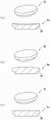
图2是表示插入部件的立体图及剖视图。2 is a perspective view and a cross-sectional view showing an insertion member.
图3是表示梁部件的立体图。3 is a perspective view showing a beam member.
图4A是表示基座板的立体图。4A is a perspective view showing a base plate.
图4B是表示其他的实施方式所涉及的基座板的使用状态的立体图及剖视图。4B is a perspective view and a cross-sectional view showing a use state of the base plate according to another embodiment.
图4C是其他的实施方式所涉及的基座板的俯视图及侧视图。4C is a plan view and a side view of a base plate according to another embodiment.
图4D是翅片的立体图。4D is a perspective view of a fin.
图4E是其他的实施方式所涉及的基座板的俯视图。4E is a plan view of a base plate according to another embodiment.
图4F是其他的实施方式所涉及的基座板的俯视图。4F is a plan view of a base plate according to another embodiment.
图4G是其他的实施方式所涉及的基座板的俯视图。4G is a plan view of a base plate according to another embodiment.
图4H是其他的实施方式所涉及的基座板的俯视图。4H is a plan view of a base plate according to another embodiment.
图4I是其他的实施方式所涉及的基座板的俯视图。4I is a plan view of a base plate according to another embodiment.
图4J是其他的实施方式所涉及的基座板的侧视图。4J is a side view of a base plate according to another embodiment.
图4K是其他的实施方式所涉及的基座板的俯视图及侧视图。4K is a plan view and a side view of a base plate according to another embodiment.
图4L是其他的实施方式所涉及的基座板的俯视图及侧视图。4L is a plan view and a side view of a base plate according to another embodiment.
图5是表示手术步骤的立体图及俯视图。5 is a perspective view and a plan view showing an operation procedure.
图6A是表示其他的实施方式所涉及的人工膝关节的使用状态的俯视图及主视图。6A is a plan view and a front view showing a use state of the artificial knee joint according to another embodiment.
图6B是表示其他的实施方式所涉及的人工膝关节的使用状态的俯视图及主视图。6B is a plan view and a front view showing a use state of the artificial knee joint according to another embodiment.
图6C是表示其他的实施方式所涉及的人工膝关节的使用状态的俯视图及主视图。6C is a plan view and a front view showing a use state of the artificial knee joint according to another embodiment.
图6D是表示其他的实施方式所涉及的人工膝关节的使用状态的俯视图及主视图。6D is a plan view and a front view showing a use state of the artificial knee joint according to another embodiment.
图6E是表示其他的实施方式所涉及的人工膝关节的使用状态的俯视图及主视图。6E is a plan view and a front view showing a use state of the artificial knee joint according to another embodiment.
图6F是表示其他的实施方式所涉及的人工膝关节的使用状态的俯视图及主视图。6F is a plan view and a front view showing a use state of the artificial knee joint according to another embodiment.
图6G是表示其他的实施方式所涉及的人工膝关节的使用状态的俯视图及主视图。6G is a plan view and a front view showing a use state of the artificial knee joint according to another embodiment.
图6H是表示其他的实施方式所涉及的人工膝关节的使用状态的俯视图及主视图。6H is a plan view and a front view showing a use state of the artificial knee joint according to another embodiment.
图7是其他的实施方式所涉及的插入部件的俯视图以及侧视图。7 is a plan view and a side view of an insertion member according to another embodiment.
具体实施方式Detailed ways
以下,参照附图,对本发明的一个实施方式的人工膝关节进行说明。本发明的人工膝关节是在变形性膝关节症、类风湿性关节炎等的治疗中的人工膝关节置换术中被使用的人工膝关节,特征在于形成能够保留半月板、韧带的构造。Hereinafter, an artificial knee joint according to an embodiment of the present invention will be described with reference to the accompanying drawings. The artificial knee joint of the present invention is an artificial knee joint used in artificial knee joint replacement in the treatment of knee osteoarthritis, rheumatoid arthritis, and the like, and is characterized by having a structure capable of retaining a meniscus and a ligament.
[人工膝关节][artificial knee joint]
图1表示人工膝关节1的使用状态。图2~图4表示人工膝关节1的构成部件。在以下的人工膝关节1的说明中,将胫骨T延伸的方向称为上下方向,将胫骨T中的患者的前后方向及左右方向分别称为前后方向及左右方向。FIG. 1 shows the use state of the
人工膝关节1具备埋设于胫骨T的内侧髁MC或外侧髁LC的关节面的一部分的插入部件2、和配置于插入部件2的下方的梁部件3。另外,人工膝关节1也可以还具备配置于插入部件2与梁部件3之间的基座板4。在图1中,插入部件2被埋设于外侧髁LC的关节面的一部分。The
插入部件2通过将胫骨T的内侧髁MC或外侧髁LC的关节面的一部分,具体地将关节面的损伤部分(磨损的部分)切除而被埋设。插入部件2通过以其表面与周围的原本的关节面平滑地连接的方式调整高度与表面形状而被埋设。The
插入部件2优选准备多种,图2示出了形状不同的插入部件2a~2c。图2表示插入部件2a~2c的立体图及剖视图。It is preferable to prepare a plurality of
插入部件2a~2c整体呈圆盘状。插入部件2a埋设于胫骨T的内侧髁MC,形成为表面凹陷的曲面。插入部件2b埋设于胫骨T的外侧髁LC,形成为表面凸出的曲面。另外,插入部件2c的表面形成为平坦面。The
在插入部件2a~2c的下表面形成有供圆筒状的基座板4的上端部嵌合的同心圆状的阶部20。此外,在不设置基座板4的情况下,不形成阶部20。A concentric circular stepped
插入部件2a~2c的直径例如为15~25mm,优选为17~22mm。实际上,预先准备直径不同的多个插入部件2a~2c,从而一边参照患者的MRI等的图像,一边选择最适的尺寸的插入部件2a~2c。The diameters of the
插入部件2a~2c的厚度例如为4mm以上。对于插入部件2a~2c而言,预先准备厚度不同的多个插入部件2a~2c,从而一边参照患者的MRI等的图像,一边选择最适的厚度的插入部件2a~2c。由此,能够使插入部件2a~2c的表面的高度与原本的关节面的高度一致。The thickness of the
另外,埋设于内侧髁MC的插入部件2a的凹陷例如为1~2mm,埋设于外侧髁LC的插入部件2b的鼓起例如为1~2mm。插入部件2a~2c的表面形成为与所埋设的部分的周围的原本的关节面平滑地连接。In addition, the depression of the
插入部件2a~2c由滑动性及耐磨损性较高的材料(例如,高分子聚乙烯等)构成。The
梁部件3沿着大致水平方向配置于插入部件2的下方,用于从下侧支承插入部件2。形成这样的筏功能的梁部件3也被称为筏销。此外,梁部件3不必与插入部件2的下表面接触。即,梁部件3也可以不与插入部件2的下表面接触,而经由胫骨T内的松质骨支承插入部件2。The
梁部件3的形状不被特别地限定,图3示出了形状不同的梁部件3a~3c。图3表示梁部件3a~3c的立体图。The shape of the
梁部件3a~3c是棒状的部件,具有长边方向的两端固定于胫骨T的皮质骨的长度。由此,梁部件3a~3c成为其两端固定于硬质的皮质骨的两端固定梁。梁部件3a~3c的长度例如为30~80mm。实际上,预先准备长度不同的多个梁部件3a~3c,在手术时利用深度仪测量供梁部件3a~3c插入的孔的深度,来选择最适的长度的梁部件3a~3c。梁部件3a~3c例如以2mm间距,优选1mm间距被准备。另外,梁部件3a~3c的宽度例如为2~8mm。The
梁部件3的截面形状不被特别地限定。梁部件3a的截面为圆形。不过,梁部件3a的截面也可以是椭圆形。The cross-sectional shape of the
梁部件3b的截面为三角形。梁部件3b在使用状态下可以如图3所示配置为使三角形的顶点朝向上方,但也可以配置为使三角形的底边朝向上方而成为倒三角形截面。使三角形的底边朝向上方来配置梁部件3b,由此提高支承插入部件2的功能。The cross section of the
梁部件3c的截面为四边形。这里,四边形是除图3所示的长方形以外,还包含正方形、梯形、菱形等的概念。The cross section of the
具有圆形截面的梁部件3a的形状较简单,但若考虑到强度,则优选具有三角形截面的梁部件3b、具有四边形截面的梁部件3c。另外,也可以相对于利用钻头等打开的圆形的贯通孔打入梁部件3b、梁部件3c。The shape of the
梁部件3a~3c由生物相容性高且刚性高的材料(例如,钛、不锈钢等)构成。The
基座板4配置于插入部件2与梁部件3之间。基座板4呈圆筒状,嵌合于在插入部件2的下表面形成的阶部20,而从下方支承插入部件2的外缘。圆筒状的基座板4的壁厚例如为1mm。The base plate 4 is arranged between the
对于基座板4而言,也可以准备多个高度不同的基座板4。由此,在调整插入部件2的高度时,也能够不通过插入部件2本身而通过基座板4进行调整。另外,也可以在基座板4与梁部件3之间另外配置未图示的高度调整用的板。For the base plate 4, a plurality of base plates 4 having different heights may be prepared. Thereby, when adjusting the height of the
基座板4不必与梁部件3接触。即,基座板4也可以不与梁部件3接触,而在两者之间夹设胫骨T的松质骨。The base plate 4 does not have to be in contact with the
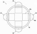
基座板4的形状不被特别地限定,图4A示出了形状不同的基座板4a~4d。图4A表示基座板4a~4d的立体图。图4B是表示基座板4d的使用状态的立体图及剖视图。The shape of the base plate 4 is not particularly limited, and FIG. 4A shows
基座板4a在圆筒部40形成有供具有四边形截面的2根梁部件3c嵌合的嵌合孔41与嵌合槽42。2根梁部件3c呈十字状配置。通过将基座板4a与梁部件3c组合,基座板4a与梁部件3c成为一体,因此提高对插入部件2进行支承的功能。The
基座板4b呈具有圆筒部40与底部43的有底圆筒状。根据该结构,能够防止插入部件2在施加了较大的载荷时下沉。The
基座板4c在圆筒部40的下部开口形成有网格状的网眼部44。根据该结构,网眼部44能够防止基座板4c的下沉,并且通过对圆筒部40进行加强来维持圆筒形状。另外,通过网眼部44来增加设置面积,由此提高对石膏(cement)设置的基座板4c进行支承的功能。The
基座板4d构成为圆筒部40的上端面相对于与圆筒轴正交的面倾斜。另一方面,圆筒部40的下端面和与圆筒轴正交的面平行。即,基座板4d的上端面相对于下端面倾斜地形成。基座板4d与图4B所示的插入部件2d组合而被使用。插入部件2d的上表面与基座板4d的上端面同样地形成为相对于与基座板4d的圆筒轴正交的面倾斜。另外,插入部件2d的阶部20与上表面平行。根据该结构,通过使基座板4d以圆筒轴为中心旋转,能够以与实际的胫骨T的关节面的高度、形状一致的方式对插入部件2d的高度进行调整。此时,也可以以插入部件2d相对于基座板4d不旋转的方式在插入部件2d的阶部20与基座板4d的上端面的彼此的接触面设置突起及与该突起嵌合的槽。突起的形状、个数不被特别地限定,例如,也可以是至少一个点状突起、以圆筒轴为中心呈放射状延伸的多个线状突起等。The
图4C~图4L表示其他的实施方式所涉及的基座板4。基座板4也可以具备圆筒部40(筒状部的一个例子)和从圆筒部40的外周面向外侧突出的突出部。在圆筒部40的外周面设置突出部,由此能够抑制基座板4下沉。4C to 4L show the base plate 4 according to other embodiments. The base plate 4 may include a cylindrical portion 40 (an example of a cylindrical portion) and a protruding portion protruding outward from the outer peripheral surface of the
图4C是基座板4e的俯视图及侧视图,图4D表示翅片45的立体图。基座板4e在圆筒部40设置有翅片45。翅片45在圆筒部40的周向设置有4个。翅片45是由与圆筒部40相同的材料形成的板状部件。翅片45具有矩形部45a与三角形部45b。三角形部45b的一部分从圆筒部40的外周面向外侧突出。三角形部45b以容易侵入松质骨的方式具有尖锐的前端。FIG. 4C is a plan view and a side view of the
圆筒部40具有使筒内与筒外连通的开口部40a。开口部40a的宽度比翅片45的矩形部45a的宽度稍宽。由此,翅片45能够经过开口部40a从筒内向筒外突出。另外,翅片45也可以具有限制从圆筒部40的外周面突出的突出量的止动部45c。止动部45c通过与圆筒部40的内周面接触而限制翅片45的移动。The
另外,如图4E所示,也可以使各翅片45的形状不同,由此改变三角形部45b从圆筒部40的外周面突出的突出量。例如,也可以在靠近皮质骨的场所减小三角形部45b的突出量,在远离皮质骨的场所增大三角形部45b的突出量。In addition, as shown in FIG. 4E , the shapes of the
图4F表示基座板4f的俯视图。基座板4f在圆筒部40设置有4个翅片46。翅片46具有矩形部46a与半圆部46b。半圆部46b的一部分从圆筒部40的外周面突出。FIG. 4F shows a plan view of the
图4G表示基座板4g的俯视图。基座板4g在圆筒部40设置有8个翅片45。此外,翅片45的数量不被特别地限定,但优选设置3个以上。FIG. 4G shows a plan view of the
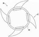
图4H表示基座板4h的俯视图。基座板4h在圆筒部40设置有4个翅片47。翅片47向相对于圆筒部40的外周面的法线方向朝周向倾斜的方向延伸。FIG. 4H shows a plan view of the
图4I表示基座板4i的俯视图。基座板4i的翅片47向与图4H所示的基座板4h不同的方向延伸。FIG. 4I shows a plan view of the
图4J表示基座板4j的侧视图。基座板4j具有从圆筒部40的外周面朝向斜下方延伸的翅片48。FIG. 4J shows a side view of the
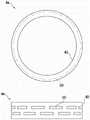
图4K所示的基座板4k在圆筒部40的外周面设置有线状物(thread)49。线状物49沿着圆筒部40的外周面在周向间歇地设置。另外,线状物49在上下方向设置有多列。此外,线状物49虽沿着圆筒部40的外周面在周向间歇地设置,但也可以在圆筒部40的外周面遍及整周地设置。线状物49优选以在将基座板4k打入胫骨时容易打入的方式使下表面朝向前端向上方倾斜(参照放大图)。The
图4L所示的基座板4m在圆筒部40的外周面设置有凹部50。凹部50沿着圆筒部40的外周面在周向间歇地设置。另外,凹部50在上下方向设置有多列。随着时间的经过,松质骨会侵入凹部50,从而抑制基座板4m的下沉。此外,凹部50虽沿着圆筒部40的外周面在周向间歇地设置,但也可以在圆筒部40的外周面遍及整周地设置。The
此外,图4C~图4L所示的圆筒部40呈上下开口的圆筒状,但也可以是设置有图4A的(b)所示那样的底部43的方式,另外,也可以是设置有图4A的(c)所示那样的网格状的网眼部44的方式。In addition, although the
[手术步骤][Surgical steps]
图5表示手术步骤的一个例子。图5的(a)所示的胫骨T的外侧髁LC的关节面磨损。首先,在外侧髁LC的关节面的下方,使用钻头等形成沿着前后方向延伸的贯通孔。贯通孔在左右方向排列形成2个。接下来,如图5的(b)所示,将梁部件3打入贯通孔中。接下来,在梁部件3的上方的外侧髁LC形成具有与插入部件2的直径对应的直径的圆孔。接下来,如图5的(c)所示,将基座板4插入在梁部件3的上方形成的圆孔。最后,如图5的(d)所示,将插入部件2嵌合于基座板4的上端。FIG. 5 shows an example of a surgical procedure. The articular surface of the lateral condyle LC of the tibia T shown in (a) of FIG. 5 is worn. First, below the articular surface of the lateral condyle LC, a drill or the like is used to form a through hole extending in the front-rear direction. Two through holes are formed side by side in the left-right direction. Next, as shown in FIG. 5( b ), the
如以上那样,本实施方式的人工膝关节1具备:插入部件2,其埋设于胫骨T的内侧髁MC或外侧髁LC的关节面的一部分;和梁部件3,其配置于插入部件2的下方,并且具有两端固定于胫骨T的皮质骨的长度。As described above, the
根据本实施方式的人工膝关节1,仅在关节面的一部分埋设插入部件2,由此能够使插入部件2的表面与其周围的剩余的关节面的高度及形状一致,因此能够再现原本的关节面的高度。另外,再现原本的关节面的高度,由此也能够保留半月板。According to the
另外,对于本实施方式的人工膝关节1而言,仅置换关节部的一部分,因此手术较容易,手术侵扰较少,且出血风险也被降低。能够保留前十字韧带(ACL),在看到前十字韧带损伤的情况下,也能够同时进行再建。另外,除半月板以外,也能够保留所有韧带,特别是,也能够保留以往较难的内侧副韧带深层(dMCL)。In addition, in the
插入部件2也可以与梁部件3接触。根据该结构,插入部件2被梁部件3从下方可靠地支承。The
插入部件2也可以不与梁部件3接触。根据该结构,能够在插入部件2与梁部件3之间设置一定程度的间隙,因此能够抑制施加了较大的载荷时的破坏。The
插入部件2中的与半月板邻接的外缘部分优选形成为圆弧状。根据该结构,能够防止与半月板的干涉,而保留半月板。The outer edge portion of the
梁部件3也可以仅沿着前后方向配置。若沿着左右方向配置梁部件3,则存在当对内侧髁MC或外侧髁LC的一方施加了较大的载荷时会经由梁部件3给内侧髁MC或外侧髁LC的另一方带来不良影响的担忧。The
本实施方式的人工膝关节1也可以还具备圆筒状的基座板4,该基座板4配置于插入部件2与梁部件3之间,对插入部件2的外缘进行支承。根据该结构,插入部件2被基座板4及梁部件3从下方可靠地支承。The
基座板4也可以与梁部件3接触。根据该结构,基座板4被梁部件3从下方可靠地支承。The base plate 4 may also be in contact with the
基座板4也可以不与梁部件3接触。根据该结构,能够在基座板4与梁部件3之间设置一定程度的间隙,因此基座板4下沉而能够适当地调节插入部件2的高度。The base plate 4 may not be in contact with the
基座板4的上部也可以具有相对于与圆筒轴正交的面倾斜的倾斜面。根据该结构,通过使基座板4以圆筒轴为中心旋转,能够以与实际的胫骨T的关节面的高度、形状一致的方式对插入部件2的高度进行调整。The upper part of the base plate 4 may have an inclined surface inclined with respect to a surface orthogonal to the cylindrical axis. According to this configuration, by rotating the base plate 4 around the cylindrical axis, the height of the
埋设于胫骨T的内侧髁MC的插入部件2a的表面优选形成为凹陷的曲面。通常,原本的内侧髁MC的关节面成为凹陷的曲面,因此根据该结构,插入部件2a的表面与周围的原本的关节面平滑地连接。The surface of the
埋设于胫骨T的外侧髁LC的插入部件2b的表面优选形成为凸出的曲面。通常,原本的外侧髁LC的关节面成为凸出的曲面,因此根据该结构,插入部件2b的表面与周围的原本的关节面平滑地连接。The surface of the
此外,人工膝关节1不限于上述的实施方式的结构,并且,不限于上述的作用效果。另外,人工膝关节1当然能够在不脱离本发明的主旨的范围内施加各种变更。例如,也可以任意地采用上述的多个实施方式的各结构、各方法等来进行组合,另外,当然也可以任意地选择一个或多个下述的各种变更例所涉及的结构、方法等,而应用于上述的实施方式所涉及的结构、方法等。In addition, the artificial knee joint 1 is not limited to the structure of the above-mentioned embodiment, and is not limited to the above-mentioned functions and effects. In addition, it is needless to say that various changes can be added to the artificial knee joint 1 without departing from the gist of the present invention. For example, each structure, each method, etc. of the above-described multiple embodiments may be arbitrarily adopted and combined, and of course, one or more structures, methods, etc. related to the following various modification examples may be arbitrarily selected. , and is applied to the structures, methods, and the like according to the above-described embodiments.
例如,图6A是在内侧髁MC及外侧髁LC的关节面的一部分分别埋设插入部件2的例子。在该图中,未示出基座板4,但也可以设置基座板4,在以下的图中也是同样的。For example, FIG. 6A shows an example in which the
图6B是插入部件2在俯视时形成D字状的例子。图6C是插入部件2在俯视时形成半圆形的例子。图6D是插入部件2在俯视时形成椭圆形的例子。FIG. 6B is an example in which the
图6E是在沿着前后方向延伸的梁部件3的基础上,还配置了沿着左右方向延伸的梁部件3的例子。FIG. 6E is an example in which
图6F是相对于各插入部件2配置了1根沿前后方向延伸的梁部件3和1根沿左右方向延伸的梁部件3的例子。图6G是相对于各插入部件2配置了1根沿前后方向延伸的梁部件3和2根沿左右方向延伸的梁部件3的例子。图6H是仅配置了3根沿左右方向延伸的梁部件3的例子。FIG. 6F is an example in which one
图7是其他的实施方式所涉及的插入部件2e的俯视图及侧视图。插入部件2e不经由基座板4地被梁部件3从下方支承。因此,插入部件2e呈不形成阶部20的圆盘状。圆盘状的插入部件2e在外周面设置有突起21。突起21沿着插入部件2e的外周面在周向间歇地设置。另外,突起21在上下方向设置有多列。突起21优选以在将插入部件2e打入胫骨时容易打入的方式使下表面朝向前端向上方倾斜(参照放大图)。FIG. 7 is a plan view and a side view of the
另外,在内侧髁MC采用人工膝关节单髁置换术(UKA),也能够仅在外侧髁LC采用人工膝关节1。In addition, the artificial knee joint unicondylar arthroplasty (UKA) can be used in the medial condyle MC, and the artificial knee joint 1 can be used only in the lateral condyle LC.
附图标记说明Description of reference numerals
1…人工膝关节;2…插入部件;2a…插入部件;2b…插入部件;2c…插入部件;2d…插入部件;3…梁部件;3a…梁部件;3b…梁部件;3c…梁部件;4…基座板;4a…基座板;4b…基座板;4c…基座板;4d…基座板;4e…基座板;4f…基座板;4g…基座板;4h…基座板;4i…基座板;4j…基座板;4k…基座板;4m…基座板;40…圆筒部;40a…开口部;43…底部;44…网眼部;45…翅片;46…翅片;47…翅片;48…翅片;49…线状物;50…凹部;T…胫骨;MC…内侧髁;LC…外侧髁。1...artificial knee joint; 2...insert part; 2a...insert part; 2b...insert part; 2c...insert part; 2d...insert part; 3...beam part; 3a...beam part; 3b...beam part; 3c...beam part 4...base plate; 4a...base plate; 4b...base plate; 4c...base plate; 4d...base plate; 4e...base plate; 4f...base plate; 4g...base plate; 4h ...base plate; 4i...base plate; 4j...base plate; 4k...base plate; 4m...base plate; 40...cylindrical portion; 40a...opening portion; 43...bottom; 44...mesh portion; 45...fin; 46...fin; 47...fin; 48...fin; 49...thread; 50...recess; T...tibia; MC...medial condyle; LC...lateral condyle.
Claims (23)
Applications Claiming Priority (3)
| Application Number | Priority Date | Filing Date | Title |
|---|---|---|---|
| JP2019-186944 | 2019-10-10 | ||
| JP2019186944 | 2019-10-10 | ||
| PCT/JP2020/038120WO2021070904A1 (en) | 2019-10-10 | 2020-10-08 | Artificial knee, and bridge member, insert member and base plate used therein |
Publications (1)
| Publication Number | Publication Date |
|---|---|
| CN114449981Atrue CN114449981A (en) | 2022-05-06 |
Family
ID=75437215
Family Applications (1)
| Application Number | Title | Priority Date | Filing Date |
|---|---|---|---|
| CN202080068239.6APendingCN114449981A (en) | 2019-10-10 | 2020-10-08 | Artificial knee joint, beam member, insert member, and base plate used for the artificial knee joint |
Country Status (5)
| Country | Link |
|---|---|
| US (1) | US20240082009A1 (en) |
| EP (1) | EP4042979B1 (en) |
| JP (2) | JP7640088B2 (en) |
| CN (1) | CN114449981A (en) |
| WO (1) | WO2021070904A1 (en) |
Citations (4)
| Publication number | Priority date | Publication date | Assignee | Title |
|---|---|---|---|---|
| US5344458A (en)* | 1992-08-06 | 1994-09-06 | Bonutti Peter M | Arthroplasty component |
| US6620199B2 (en)* | 2001-07-13 | 2003-09-16 | Ronald P. Grelsamer | Device for reinforcing bone in partial knee replacement surgery |
| US20040106928A1 (en)* | 2002-12-03 | 2004-06-03 | Steven Ek | Tibial resurfacing system |
| US20050209701A1 (en)* | 2004-03-17 | 2005-09-22 | Toru Suguro And Nakashima Propeller Co., Ltd. | Artificial knee joint |
Family Cites Families (8)
| Publication number | Priority date | Publication date | Assignee | Title |
|---|---|---|---|---|
| US5092895A (en)* | 1990-05-30 | 1992-03-03 | Albrektsson Bjoern | Knee-joint prosthesis |
| JP3350080B2 (en)* | 1992-01-31 | 2002-11-25 | 京セラ株式会社 | Artificial vertebral body spacer |
| ATE272372T1 (en) | 1999-09-24 | 2004-08-15 | Ct Pulse Orthopedics Ltd | TIBIAL PART FOR A KNEE JOINT PROSTHESIS AND KIT WITH SUCH A TIBIAL PART |
| US7678151B2 (en)* | 2000-05-01 | 2010-03-16 | Ek Steven W | System and method for joint resurface repair |
| US6494914B2 (en)* | 2000-12-05 | 2002-12-17 | Biomet, Inc. | Unicondylar femoral prosthesis and instruments |
| US8915965B2 (en) | 2009-05-07 | 2014-12-23 | Depuy (Ireland) | Anterior stabilized knee implant |
| CA3066766C (en) | 2015-01-21 | 2021-09-14 | Active Implants LLC | Partial unicompartmental system for partial knee replacement |
| CN109199648A (en)* | 2017-07-03 | 2019-01-15 | 天津富华医疗科技有限公司 | Artificial knee joint |
- 2020
- 2020-10-08CNCN202080068239.6Apatent/CN114449981A/enactivePending
- 2020-10-08JPJP2021551701Apatent/JP7640088B2/enactiveActive
- 2020-10-08EPEP20874944.0Apatent/EP4042979B1/enactiveActive
- 2020-10-08USUS17/754,744patent/US20240082009A1/enactivePending
- 2020-10-08WOPCT/JP2020/038120patent/WO2021070904A1/ennot_activeCeased
- 2024
- 2024-11-06JPJP2024194718Apatent/JP2025010449A/enactivePending
Patent Citations (4)
| Publication number | Priority date | Publication date | Assignee | Title |
|---|---|---|---|---|
| US5344458A (en)* | 1992-08-06 | 1994-09-06 | Bonutti Peter M | Arthroplasty component |
| US6620199B2 (en)* | 2001-07-13 | 2003-09-16 | Ronald P. Grelsamer | Device for reinforcing bone in partial knee replacement surgery |
| US20040106928A1 (en)* | 2002-12-03 | 2004-06-03 | Steven Ek | Tibial resurfacing system |
| US20050209701A1 (en)* | 2004-03-17 | 2005-09-22 | Toru Suguro And Nakashima Propeller Co., Ltd. | Artificial knee joint |
Also Published As
| Publication number | Publication date |
|---|---|
| JPWO2021070904A1 (en) | 2021-04-15 |
| JP2025010449A (en) | 2025-01-20 |
| EP4042979A1 (en) | 2022-08-17 |
| WO2021070904A1 (en) | 2021-04-15 |
| JP7640088B2 (en) | 2025-03-05 |
| EP4042979A4 (en) | 2023-02-22 |
| US20240082009A1 (en) | 2024-03-14 |
| EP4042979B1 (en) | 2025-06-18 |
Similar Documents
| Publication | Publication Date | Title |
|---|---|---|
| US10952862B2 (en) | Cruciate-retaining knee prosthesis | |
| JP6661578B2 (en) | Improved glenoid component | |
| JP4045194B2 (en) | Artificial knee joint | |
| CA2906631C (en) | Unicondylar tibial knee implant | |
| JP5128497B2 (en) | Patellar component | |
| EP1872746B1 (en) | Tibial insert having multiple keels | |
| CN104095664B (en) | Distal femur clamp assembly and the distal femur cutting device with this assembly | |
| JP5999745B2 (en) | Artificial ankle | |
| US20220346963A1 (en) | Knee joint prosthesis and tibial component thereof | |
| KR20020015682A (en) | A prosthesis structure | |
| JP2008528110A (en) | Pulley groove implant and related methods and instruments | |
| JPH03267055A (en) | Shank side component of artificial knee joint | |
| CN101222886A (en) | artificial knee joint | |
| CN106031667B (en) | Artificial knee joint and tibia component and femur component thereof | |
| JP2016531599A (en) | Reverse knee prosthesis | |
| CN112135584A (en) | patella implant | |
| CN114449981A (en) | Artificial knee joint, beam member, insert member, and base plate used for the artificial knee joint | |
| AU2017268219A1 (en) | Unicondylar tibia implants |
Legal Events
| Date | Code | Title | Description |
|---|---|---|---|
| PB01 | Publication | ||
| PB01 | Publication | ||
| SE01 | Entry into force of request for substantive examination | ||
| SE01 | Entry into force of request for substantive examination |