CN114447676A - Charging gun and its stress relief structure - Google Patents
Charging gun and its stress relief structureDownload PDFInfo
- Publication number
- CN114447676A CN114447676ACN202011205427.7ACN202011205427ACN114447676ACN 114447676 ACN114447676 ACN 114447676ACN 202011205427 ACN202011205427 ACN 202011205427ACN 114447676 ACN114447676 ACN 114447676A
- Authority
- CN
- China
- Prior art keywords
- shell
- housing
- protrusions
- cable
- charging gun
- Prior art date
- Legal status (The legal status is an assumption and is not a legal conclusion. Google has not performed a legal analysis and makes no representation as to the accuracy of the status listed.)
- Pending
Links
Images


Classifications
- H—ELECTRICITY
- H01—ELECTRIC ELEMENTS
- H01R—ELECTRICALLY-CONDUCTIVE CONNECTIONS; STRUCTURAL ASSOCIATIONS OF A PLURALITY OF MUTUALLY-INSULATED ELECTRICAL CONNECTING ELEMENTS; COUPLING DEVICES; CURRENT COLLECTORS
- H01R13/00—Details of coupling devices of the kinds covered by groups H01R12/70 or H01R24/00 - H01R33/00
- H01R13/58—Means for relieving strain on wire connection, e.g. cord grip, for avoiding loosening of connections between wires and terminals within a coupling device terminating a cable
- H01R13/5804—Means for relieving strain on wire connection, e.g. cord grip, for avoiding loosening of connections between wires and terminals within a coupling device terminating a cable comprising a separate cable clamping part
- H01R13/5812—Means for relieving strain on wire connection, e.g. cord grip, for avoiding loosening of connections between wires and terminals within a coupling device terminating a cable comprising a separate cable clamping part the cable clamping being achieved by mounting the separate part on the housing of the coupling device
- H—ELECTRICITY
- H01—ELECTRIC ELEMENTS
- H01R—ELECTRICALLY-CONDUCTIVE CONNECTIONS; STRUCTURAL ASSOCIATIONS OF A PLURALITY OF MUTUALLY-INSULATED ELECTRICAL CONNECTING ELEMENTS; COUPLING DEVICES; CURRENT COLLECTORS
- H01R13/00—Details of coupling devices of the kinds covered by groups H01R12/70 or H01R24/00 - H01R33/00
- H01R13/46—Bases; Cases
- H01R13/502—Bases; Cases composed of different pieces
- B—PERFORMING OPERATIONS; TRANSPORTING
- B60—VEHICLES IN GENERAL
- B60L—PROPULSION OF ELECTRICALLY-PROPELLED VEHICLES; SUPPLYING ELECTRIC POWER FOR AUXILIARY EQUIPMENT OF ELECTRICALLY-PROPELLED VEHICLES; ELECTRODYNAMIC BRAKE SYSTEMS FOR VEHICLES IN GENERAL; MAGNETIC SUSPENSION OR LEVITATION FOR VEHICLES; MONITORING OPERATING VARIABLES OF ELECTRICALLY-PROPELLED VEHICLES; ELECTRIC SAFETY DEVICES FOR ELECTRICALLY-PROPELLED VEHICLES
- B60L53/00—Methods of charging batteries, specially adapted for electric vehicles; Charging stations or on-board charging equipment therefor; Exchange of energy storage elements in electric vehicles
- B60L53/10—Methods of charging batteries, specially adapted for electric vehicles; Charging stations or on-board charging equipment therefor; Exchange of energy storage elements in electric vehicles characterised by the energy transfer between the charging station and the vehicle
- B60L53/14—Conductive energy transfer
- B60L53/16—Connectors, e.g. plugs or sockets, specially adapted for charging electric vehicles
- H—ELECTRICITY
- H01—ELECTRIC ELEMENTS
- H01R—ELECTRICALLY-CONDUCTIVE CONNECTIONS; STRUCTURAL ASSOCIATIONS OF A PLURALITY OF MUTUALLY-INSULATED ELECTRICAL CONNECTING ELEMENTS; COUPLING DEVICES; CURRENT COLLECTORS
- H01R13/00—Details of coupling devices of the kinds covered by groups H01R12/70 or H01R24/00 - H01R33/00
- H01R13/56—Means for preventing chafing or fracture of flexible leads at outlet from coupling part
- H01R13/562—Bending-relieving
- H—ELECTRICITY
- H01—ELECTRIC ELEMENTS
- H01R—ELECTRICALLY-CONDUCTIVE CONNECTIONS; STRUCTURAL ASSOCIATIONS OF A PLURALITY OF MUTUALLY-INSULATED ELECTRICAL CONNECTING ELEMENTS; COUPLING DEVICES; CURRENT COLLECTORS
- H01R13/00—Details of coupling devices of the kinds covered by groups H01R12/70 or H01R24/00 - H01R33/00
- H01R13/58—Means for relieving strain on wire connection, e.g. cord grip, for avoiding loosening of connections between wires and terminals within a coupling device terminating a cable
- H01R13/582—Means for relieving strain on wire connection, e.g. cord grip, for avoiding loosening of connections between wires and terminals within a coupling device terminating a cable the cable being clamped between assembled parts of the housing
- H01R13/5825—Means for relieving strain on wire connection, e.g. cord grip, for avoiding loosening of connections between wires and terminals within a coupling device terminating a cable the cable being clamped between assembled parts of the housing the means comprising additional parts captured between housing parts and cable
- H—ELECTRICITY
- H01—ELECTRIC ELEMENTS
- H01R—ELECTRICALLY-CONDUCTIVE CONNECTIONS; STRUCTURAL ASSOCIATIONS OF A PLURALITY OF MUTUALLY-INSULATED ELECTRICAL CONNECTING ELEMENTS; COUPLING DEVICES; CURRENT COLLECTORS
- H01R2201/00—Connectors or connections adapted for particular applications
- H01R2201/26—Connectors or connections adapted for particular applications for vehicles
- Y—GENERAL TAGGING OF NEW TECHNOLOGICAL DEVELOPMENTS; GENERAL TAGGING OF CROSS-SECTIONAL TECHNOLOGIES SPANNING OVER SEVERAL SECTIONS OF THE IPC; TECHNICAL SUBJECTS COVERED BY FORMER USPC CROSS-REFERENCE ART COLLECTIONS [XRACs] AND DIGESTS
- Y02—TECHNOLOGIES OR APPLICATIONS FOR MITIGATION OR ADAPTATION AGAINST CLIMATE CHANGE
- Y02T—CLIMATE CHANGE MITIGATION TECHNOLOGIES RELATED TO TRANSPORTATION
- Y02T10/00—Road transport of goods or passengers
- Y02T10/60—Other road transportation technologies with climate change mitigation effect
- Y02T10/70—Energy storage systems for electromobility, e.g. batteries
- Y—GENERAL TAGGING OF NEW TECHNOLOGICAL DEVELOPMENTS; GENERAL TAGGING OF CROSS-SECTIONAL TECHNOLOGIES SPANNING OVER SEVERAL SECTIONS OF THE IPC; TECHNICAL SUBJECTS COVERED BY FORMER USPC CROSS-REFERENCE ART COLLECTIONS [XRACs] AND DIGESTS
- Y02—TECHNOLOGIES OR APPLICATIONS FOR MITIGATION OR ADAPTATION AGAINST CLIMATE CHANGE
- Y02T—CLIMATE CHANGE MITIGATION TECHNOLOGIES RELATED TO TRANSPORTATION
- Y02T10/00—Road transport of goods or passengers
- Y02T10/60—Other road transportation technologies with climate change mitigation effect
- Y02T10/7072—Electromobility specific charging systems or methods for batteries, ultracapacitors, supercapacitors or double-layer capacitors
- Y—GENERAL TAGGING OF NEW TECHNOLOGICAL DEVELOPMENTS; GENERAL TAGGING OF CROSS-SECTIONAL TECHNOLOGIES SPANNING OVER SEVERAL SECTIONS OF THE IPC; TECHNICAL SUBJECTS COVERED BY FORMER USPC CROSS-REFERENCE ART COLLECTIONS [XRACs] AND DIGESTS
- Y02—TECHNOLOGIES OR APPLICATIONS FOR MITIGATION OR ADAPTATION AGAINST CLIMATE CHANGE
- Y02T—CLIMATE CHANGE MITIGATION TECHNOLOGIES RELATED TO TRANSPORTATION
- Y02T90/00—Enabling technologies or technologies with a potential or indirect contribution to GHG emissions mitigation
- Y02T90/10—Technologies relating to charging of electric vehicles
- Y02T90/14—Plug-in electric vehicles
Landscapes
- Engineering & Computer Science (AREA)
- Power Engineering (AREA)
- Transportation (AREA)
- Mechanical Engineering (AREA)
- Details Of Connecting Devices For Male And Female Coupling (AREA)
- Electric Propulsion And Braking For Vehicles (AREA)
- Installation Of Indoor Wiring (AREA)
- Charge And Discharge Circuits For Batteries Or The Like (AREA)
Abstract
Description
Translated fromChinese技术领域technical field
本案是关于一种充电设备,尤指一种具应力舒缓结构的充电枪。This case is about a charging device, especially a charging gun with a stress relief structure.
背景技术Background technique
一般而言,充电设备包含充电枪与供电装置,通过充电枪连接供电装置与外部装置,以使供电装置对外部装置进行充电。充电枪的线缆,例如电源线等,在使用过程中会被经常性的弯折,使靠近连接端子处的线缆可能会因应力过大而发生断裂的情形。Generally speaking, a charging device includes a charging gun and a power supply device, and the power supply device and the external device are connected through the charging gun, so that the power supply device charges the external device. The cables of the charging gun, such as power cables, are often bent during use, so that the cables near the connection terminals may be broken due to excessive stress.
目前市面上有许多充电枪在线缆靠近连接端子处设有应力舒缓结构,该应力舒缓结构为一体成型的环型结构,该应力舒缓结构环绕设置于线缆的外侧。然而,上述的线缆通常透过人工组装的方式穿设于应力舒缓结构中,且必须于组装前先行涂抹润滑油于应力舒缓结构内缘,以减缓组装的摩擦力,导致组装过程耗时且不便、生产效率低,亦无法达到防水效果。At present, many charging guns on the market are provided with a stress relief structure near the connection terminal of the cable. The stress relief structure is an integrally formed annular structure, and the stress relief structure is arranged around the outer side of the cable. However, the above-mentioned cables are usually threaded into the stress relief structure by manual assembly, and lubricating oil must be applied to the inner edge of the stress relief structure before assembly to reduce the frictional force of the assembly, resulting in a time-consuming and time-consuming assembly process. It is inconvenient, the production efficiency is low, and the waterproof effect cannot be achieved.
因此,实有必要发展一种充电枪及应力舒缓结构,以解决现有技术所面临的问题。Therefore, it is necessary to develop a charging gun and a stress relief structure to solve the problems faced by the prior art.
发明内容SUMMARY OF THE INVENTION
本案的目的在于提供一种充电枪及其应力舒缓结构,其可达到易于组装线缆、节省人力组装的工时、提升产品生产效率、稳定度以及防水等效果。The purpose of this case is to provide a charging gun and its stress relief structure, which can achieve the effects of easy assembly of cables, saving man-hours for assembly, and improving product production efficiency, stability, and waterproofing.
为达上述目的,本案的一较广义实施样态为提供一种充电枪,包括线缆、外壳及应力舒缓结构。线缆包含表面。外壳包含第一壳体与第二壳体。第一壳体可分离地与第二壳体组接。应力舒缓结构包含第一部分及第二部分。第一部分可分离地与第二部分组接,第一部分设置于第一壳体的第一内壁上,第二部分设置于第二壳体的第二内壁上。第一壳体与第二壳体相组接,使第一部分及第二部分相组接,第一部分包覆于至少部分的线缆的表面上,第二部分包覆于至少部分的线缆的表面上,且应力舒缓结构夹设于线缆与外壳之间。To achieve the above purpose, a broader implementation aspect of this case is to provide a charging gun, including a cable, a casing and a stress relief structure. Cables contain surfaces. The casing includes a first casing and a second casing. The first casing is detachably assembled with the second casing. The stress relief structure includes a first part and a second part. The first part is detachably assembled with the second part, the first part is arranged on the first inner wall of the first casing, and the second part is arranged on the second inner wall of the second casing. The first shell is assembled with the second shell, so that the first part and the second part are assembled, the first part is covered on the surface of at least part of the cable, and the second part is covered on the surface of at least part of the cable. on the surface, and the stress relief structure is sandwiched between the cable and the casing.
为达上述目的,本案的另一较广义实施样态为提供一种应力舒缓结构,第一部分、第二部分及多个第一环形凸部。第二部分可分离地与第一部分组接。多个第一环形凸部设置于第一部分及第二部分。第一部分及第二部分相组接,使第一部分包覆于至少部分的线缆的表面上,且使第二部分包覆于至少部分的线缆的表面上,多个第一环形凸部可分离地抵顶于线缆的表面上。To achieve the above objective, another broader implementation aspect of the present application is to provide a stress relief structure comprising a first portion, a second portion and a plurality of first annular convex portions. The second part is detachably assembled with the first part. A plurality of first annular protrusions are disposed on the first part and the second part. The first part and the second part are assembled together, so that the first part covers at least part of the surface of the cable, and the second part covers at least part of the surface of the cable, and the plurality of first annular protrusions can be separately against the surface of the cable.
附图说明Description of drawings
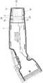
图1为本案较佳实施例的充电枪的结构示意图;1 is a schematic structural diagram of a charging gun according to a preferred embodiment of the present invention;
图2为图1所示充电枪的壳体及应力舒缓结构的结构分解示意图;FIG. 2 is a schematic structural exploded view of the housing and the stress relief structure of the charging gun shown in FIG. 1;
图3为图1所示的充电枪的壳体及应力舒缓结构的于另一视角的结构分解示意图;3 is a schematic structural exploded view of the housing and the stress relief structure of the charging gun shown in FIG. 1 from another perspective;
图4为图1所示的充电枪的壳体及应力舒缓结构的剖面结构示意图;FIG. 4 is a schematic cross-sectional structural diagram of the housing and the stress relief structure of the charging gun shown in FIG. 1;
图5为图1所示的充电枪的剖面结构示意图。FIG. 5 is a schematic cross-sectional structure diagram of the charging gun shown in FIG. 1 .
【符号说明】【Symbol Description】
100:充电枪100: Charging gun
1:外壳1: Shell
10:端部10: End
11:第一壳体11: The first shell
11a:第一内壁11a: First inner wall
12:第二壳体12: Second shell
12a:第二内壁12a: Second inner wall
13:第二环形凸部13: Second annular protrusion
13a:第三凸部13a: Third convex part
13b:第四凸部13b: Fourth convex portion
14:锁固元件14: Locking element
14a:第一锁固部14a: The first locking part
14b:第二锁固部14b: Second locking part
2:应力舒缓结构2: Stress relief structure
21:第一部分21: Part One
21a:第一内表面21a: First inner surface
21b:第一外表面21b: First outer surface
22:第二部分22: Part Two
22a:第二内表面22a: Second inner surface
22b:第二外表面22b: Second outer surface
23:第一环形凸部23: The first annular protrusion
23a:第一凸部23a: First convex part
23b:第二凸部23b: Second convex part
24:环形凹部24: Annular recess
24a:第一凹部24a: First recess
24b:第二凹部24b: Second recess
3:线缆3: Cable
31:表面31: Surface
具体实施方式Detailed ways
体现本案特征与优点的一些典型实施例将在后段的说明中详细叙述。应理解的是本案能够在不同的态样上具有各种的变化,其皆不脱离本案的范围,且其中的说明及图示在本质上是当作说明之用,而非架构于限制本案。Some typical embodiments embodying the features and advantages of the present case will be described in detail in the description of the following paragraphs. It should be understood that this case can have various changes in different aspects, all of which do not depart from the scope of this case, and the descriptions and diagrams therein are essentially for illustrative purposes rather than limiting the present case.
请参阅图1至图5,其中图1为本案较佳实施例的充电枪的结构示意图,图2为图1所示充电枪的壳体及应力舒缓结构的结构分解示意图,图3为图1所示的充电枪的壳体及应力舒缓结构的于另一视角的结构分解示意图,图4为图1所示的充电枪的壳体及应力舒缓结构的剖面结构示意图,图5为图1所示的充电枪的剖面结构示意图。本实施例的充电枪100包括外壳1、应力舒缓结构2及线缆3。线缆3包含表面31。外壳1包含第一壳体11与第二壳体12,其中第一壳体11可分离地与第二壳体12组接。应力舒缓结构2包含第一部分21、第二部分22及多个第一环形凸部23。第一部分21可分离地与第二部分22组接,第一部分21设置于第一壳体11的第一内壁11a上,第二部分22设置于第二壳体12的第二内壁12a上,多个第一环形凸部23设置于第一部分21及第二部分22上。透过第一壳体11与第二壳体12相组接,使第一部分21及第二部分22相组接,且第一部分21包覆于至少部分的线缆3的表面31上,第二部分22亦包覆于至少部分的线缆3的表面31上,且应力舒缓结构2环绕于线缆3而设置,并使应力舒缓结构2夹设于线缆3与外壳1之间,多个第一环形凸部23可分离地抵顶于线缆3的表面31上。当线缆3受力产生弯折时,应力舒缓结构2产生相对应于弯折应力的支撑力,避免线缆3过度弯折而断裂。此外,本案透过第一壳体11及第一部分21与第二壳体12及第二部分22可分离地组装于线缆3上,无需于组装前先行涂抹润滑油及壳完成组装,达到简化组装过程、提升生产效率等效果。Please refer to FIG. 1 to FIG. 5 , wherein FIG. 1 is a schematic structural diagram of a charging gun according to a preferred embodiment of the present invention, FIG. 2 is a structural exploded schematic diagram of a housing and a stress relief structure of the charging gun shown in FIG. 1 , and FIG. 3 is FIG. 1 Figure 4 is a schematic cross-sectional structural diagram of the housing and stress relief structure of the charging gun shown in Figure 1, and Figure 5 is a schematic diagram of the structure shown in Figure 1. Schematic diagram of the cross-sectional structure of the charging gun shown. The charging
于一实施例中,充电枪100的线缆3是架构于传输电能,其中线缆3包含第一端(未图示)及第二端(未图示)。第一端及第二端分别为线缆3的两相对端部,其中第一端电性连接至一供电装置(未图示),其中该供电装置例如但不限为一充电桩。第二端包含一连接器(未图示),其中该连接器架构于电性连接至一外部装置(未图示),该外部装置例如但不限为一电动车。其中,当该连接器与该外部装置电性连接时,该供电装置输出电能,并透过线缆3传输至该外部装置,以对该外部装置充电。In one embodiment, the
请参阅图2至图3,于本实施例中,应力舒缓结构2的第一部分21与第二部分22各自为一半环形截面的片状结构,当第一部分21与第二部分22接合时,以构成环形的应力舒缓结构2,但不以此为限。于本实施例中,应力舒缓结构2的第一部分21包含第一内表面21a及第一外表面21b,第一内表面21a及第一外表面21b分别为第一部分21的两相对侧的表面。应力舒缓结构2的第二部分22包含第二内表面22a及第二外表面22b,第二内表面22a及第二外表面22b分别为第二部分22的两相对侧的表面。其中,应力舒缓结构2的第一部分21的第一外表面21b与外壳1的第一壳体11的第一内壁11a相互匹配,应力舒缓结构2的第二部分22的第二外表面22b与外壳1的第二壳体12的第二内壁12a相互匹配。透过一外力将外壳1的第一壳体11及第二壳体12组装,使外壳1施加压力于应力舒缓结构2而紧密接合,以防止水或液体由外壳1与应力舒缓结构2之间的空隙渗入装置内部,以提升防水效果。Referring to FIGS. 2 to 3 , in this embodiment, the
请参阅图2至图4,于本实施例中,应力舒缓结构2的第一部分21包含多个第一凸部23a,其中每一个第一凸部23a是由第一内表面21a向外凸起形成的半环形凸起结构,且多个第一凸部23a彼此相邻且间隔设置。应力舒缓结构2的第二部分22包含多个第二凸部23b,其中每一个第二凸部23b是由第二内表面22a向外凸起形成的半环形凸起结构,且多个第二凸部23b彼此相邻且间隔设置。当应力舒缓结构2的第一部分21与第二部分22相组接时,多个第一凸部23a分别连接对应的第二凸部23b,以形成多个第一环形凸部23。当应力舒缓结构2包覆于线缆3外侧时,多个第一环形凸部23分别抵顶于线缆3的表面上。透过多个第一环形凸部23的设置,使线缆3与应力舒缓结构2更紧密接合,以防止水或液体由线缆3与应力舒缓结构2之间的空隙渗入装置内部,并提升防水效果。Referring to FIGS. 2 to 4 , in the present embodiment, the
请参阅图2至图4,于本实施例中,应力舒缓结构2的第一部分21的第一外表面21b上具有多个第一凹部24a,其中多个第一凹部24a为分别由第一外表面21b向内凹陷形成的半环形凹槽结构,且彼此相邻且间隔设置。应力舒缓结构2的第二部分22的第二外表面22b具有多个第二凹部24b,其中多个第二凹部24b为分别由第二外表面22b向内凹陷形成的半环形凹槽结构,且彼此相邻且间隔设置。当应力舒缓结构2的第一部分21与第二部分22接合时,多个第一凹部24a各自接合至对应的第二凹部24b,以形成多个环形凹部24。Referring to FIGS. 2 to 4 , in this embodiment, the first
请参阅图2至图4,于本实施例中,本实施例的外壳1的第一内壁11a具有多个第三凸部13a,其中每一个第三凸部13a是由第一内壁11a向外凸起形成的半环形凸起结构,且多个第三凸部13a彼此相邻且间隔设置。本实施例的外壳1的第二内壁12a具有多个第四凸部13b,其中每一个第四凸部13b是由第二内壁12a向外凸起形成的半环形凸起结构,且多个第四凸部13b彼此相邻且间隔设置。当外壳1的第一壳体11与第二壳体12相组接时,应力舒缓结构2的第一部分21与第二部分22亦相组接,且多个第三凸部13a分别连接对应的第四凸部13b,以形成多个第二环形凸部13。Referring to FIGS. 2 to 4 , in this embodiment, the first
请参阅图2至图4,于本实施例中,外壳1的多个第二环形凸部13与应力舒缓结构2的多个环形凹部24的数量相同,且位置相互对应,是以,每一个第二环形凸部13是可分离地设置于所对应的环形凹部24中。透过外壳1的多个第二环形凸部13设置于对应的应力舒缓结构2所对应的的环形凹部24中,使应力舒缓结构2与外壳1相互匹配且紧密接合,防止水或液体由外壳1与应力舒缓结构2之间的空隙渗入装置内部,以提升防水效果。本案的充电枪100的环形凹部24及第二环形凸部13的数量及设置方式不以上述实施态样为限,其可依据实际情况任施变化。于本实施例中,应力舒缓结构2为一防水材料制成,例如橡胶等材料,但不以此为限。Referring to FIGS. 2 to 4 , in this embodiment, the plurality of second annular
请参阅图1、图4及图5,于本实施例中,应力舒缓结构2邻设于外壳1的端部10,且外壳1完整包覆应力舒缓结构2。换言之,应力舒缓结构2未露出于外壳1的端部10的开口之外。透过外壳1完整包覆应力舒缓结构2,以限制应力舒缓结构2的变形幅度,借此降低线缆3被过度弯折而断裂的风险。Referring to FIGS. 1 , 4 and 5 , in this embodiment, the
请参阅图2及图3,于本实施例中,充电枪100的外壳1还包含多个锁固元件14,其中多个锁固元件14是架构于固定第一壳体11与第二壳体12,但不以此为限。每一个锁固元件14还包含第一锁固部14a及一第二锁固部14b。第一锁固部14a设置于第一壳体11,第二锁固部14b设置于第二壳体12上。当第一壳体11与第二壳体12组接时,每一个锁固元件14的第一锁固部14a及一第二锁固部14b相互接合,使第一壳体11固定于第二壳体12,以实现外壳1的组装,且避免第一壳体11与第二壳体12被施加于应力舒缓结构2压力弹开。于本实施例中,锁固元件14的第一锁固部14a设置于第一壳体11的第一内壁11a上,第二锁固部14b设置于第二壳体12的第二内壁12a上,且第一锁固部14a与第二锁固部14b是以卡扣的方式固定第一壳体11与第二壳体12,但不以此为限。于一些实施例中,锁固元件14亦可为磁吸或紧配等方式固定,均不以此为限。Please refer to FIG. 2 and FIG. 3 , in this embodiment, the housing 1 of the charging
请参阅图1至图5,于本实施例的充电枪100是透过分离式的外壳1与分离式的应力舒缓结构2组装于至少部分的线缆3,来达到简化组装过程、提升生产效率、防水等效果。首先,应力舒缓结构2的第一部分21设置于外壳1的第一壳体11内,其中第一部分21与第一壳体11均为半环形截面的片状结构,且第一部分21的第一外表面21b与第一壳体11的第一内壁11a相互匹配,使第一部分21紧密贴合于第一壳体11;应力舒缓结构2的第二部分22设置于外壳1的第二壳体12内,其中第二部分22与第二壳体12均为半环形截面的片状结构,且第二部分22的第二外表面22b与第二壳体12的第二内壁12a相互匹配,使第二部分22紧密贴合于第二壳体12。接着,将第一壳体11与第一部分21对应组接至第二壳体12与第二部分22,并且使第一部分21及第二部分22环绕包覆于线缆3之外。最后,再透过外力压合第一壳体11及第二壳体12,且多个锁固元件14固定第一壳体11及第二壳体12。如此一来,应力舒缓结构2被夹设于外壳1与线缆3之间,使应力舒缓结构2与外壳1紧密贴合而达到防水效果,以及应力舒缓结构2与线缆3之间亦紧密贴合而达到防水效果。透过上述分离式的外壳1与分离式的应力舒缓结构2组装于线缆3,达到简化组装过程、提升生产效率、防水等效果。Referring to FIGS. 1 to 5 , the charging
综上所述,本案透过外壳的第一壳体及应力舒缓结构的第一部分与外壳的第二壳体及应力舒缓结构的第二部分可分离地组装于线缆上,无需于组装前先行涂抹润滑油及壳完成组装,达到简化组装过程、提升生产效率等效果。此外,本案透过应力舒缓结构与外壳相互匹配,且外壳对应力舒缓结构施加压力,使外壳与应力舒缓结构紧密接合,以防止水或液体由外壳与应力舒缓结构之间的空隙渗入装置内部,以提升防水效果。再者,本案透过第一环形凸部的设置,使线缆与应力舒缓结构更紧密接合,以防止水或液体由线缆与应力舒缓结构之间的空隙渗入装置内部,并提升防水效果。To sum up, in this case, the first shell of the outer shell and the first part of the stress relief structure and the second shell of the outer shell and the second part of the stress relief structure can be detachably assembled on the cable, and there is no need to assemble it first. Apply lubricating oil and shell to complete the assembly, to simplify the assembly process and improve production efficiency. In addition, in this case, the stress relief structure is matched with the outer shell, and the outer shell exerts pressure on the stress relief structure, so that the outer shell and the stress relief structure are closely joined to prevent water or liquid from infiltrating the inside of the device through the gap between the outer shell and the stress relief structure. to improve the waterproof effect. Furthermore, through the arrangement of the first annular convex portion in this case, the cable and the stress relief structure are more closely joined, so as to prevent water or liquid from infiltrating the inside of the device through the gap between the cable and the stress relief structure, and improve the waterproof effect.
本案得由熟知此技术的人士任施匠思而为诸般修饰,然皆不脱如所附的权利要求书所欲保护的范围。This case can be modified in various ways by a person familiar with this technology, but it does not deviate from the scope of protection intended by the appended claims.
Claims (13)
Priority Applications (3)
| Application Number | Priority Date | Filing Date | Title |
|---|---|---|---|
| CN202011205427.7ACN114447676A (en) | 2020-11-02 | 2020-11-02 | Charging gun and its stress relief structure |
| US17/347,146US11646529B2 (en) | 2020-11-02 | 2021-06-14 | Charging gun and strain relief structure thereof |
| EP21181770.5AEP3993179B1 (en) | 2020-11-02 | 2021-06-25 | Charging gun and strain relief structure thereof |
Applications Claiming Priority (1)
| Application Number | Priority Date | Filing Date | Title |
|---|---|---|---|
| CN202011205427.7ACN114447676A (en) | 2020-11-02 | 2020-11-02 | Charging gun and its stress relief structure |
Publications (1)
| Publication Number | Publication Date |
|---|---|
| CN114447676Atrue CN114447676A (en) | 2022-05-06 |
Family
ID=76623963
Family Applications (1)
| Application Number | Title | Priority Date | Filing Date |
|---|---|---|---|
| CN202011205427.7APendingCN114447676A (en) | 2020-11-02 | 2020-11-02 | Charging gun and its stress relief structure |
Country Status (3)
| Country | Link |
|---|---|
| US (1) | US11646529B2 (en) |
| EP (1) | EP3993179B1 (en) |
| CN (1) | CN114447676A (en) |
Families Citing this family (4)
| Publication number | Priority date | Publication date | Assignee | Title |
|---|---|---|---|---|
| CN114552277A (en)* | 2020-11-24 | 2022-05-27 | 台达电子工业股份有限公司 | charging gun |
| CN115131914B (en)* | 2022-06-29 | 2023-12-05 | 东风汽车有限公司东风日产乘用车公司 | Charging port cover control method, device, equipment and storage medium |
| USD1044736S1 (en)* | 2023-07-21 | 2024-10-01 | Weihuang Mai | Charging gun |
| USD1079618S1 (en)* | 2023-07-28 | 2025-06-17 | Guangdong Chongwei technology Co., LTD | Charging gun |
Citations (6)
| Publication number | Priority date | Publication date | Assignee | Title |
|---|---|---|---|---|
| CN102957028A (en)* | 2011-08-22 | 2013-03-06 | 李尔公司 | Connector assembly |
| US20150147919A1 (en)* | 2013-11-28 | 2015-05-28 | Phoenix Contact Gmbh & Co. Kg | Charging cable connector |
| CN105490241A (en)* | 2016-01-12 | 2016-04-13 | 浙江亿电电气有限公司 | Pipe jacket plugging device |
| US20160315414A1 (en)* | 2015-04-27 | 2016-10-27 | Tyco Electronics Corporation | Connector housing assembly for sealing to a cable |
| CN205791392U (en)* | 2016-05-27 | 2016-12-07 | 国家电网公司 | Transmission line of electricity protects wire type suspension clamp |
| CN208489423U (en)* | 2018-06-29 | 2019-02-12 | 深圳灵科技术有限公司 | A kind of charging gun shell structure |
Family Cites Families (9)
| Publication number | Priority date | Publication date | Assignee | Title |
|---|---|---|---|---|
| WO2007112771A1 (en)* | 2006-04-04 | 2007-10-11 | Fci | Retention ferrule for cable connector |
| CN101098061A (en) | 2006-06-27 | 2008-01-02 | 富士康(昆山)电脑接插件有限公司 | Cable Connector Assembly |
| US20150144394A1 (en) | 2012-05-14 | 2015-05-28 | Next Wave Design Pty Ltd | Cable holder |
| EP2816672B1 (en)* | 2013-06-21 | 2016-11-16 | Delphi Technologies, Inc. | Strain relief system for an electrical connector assembly |
| DE102014008343A1 (en) | 2014-06-04 | 2015-12-17 | Kostal Kontakt Systeme Gmbh | Electric device |
| TWM536429U (en) | 2016-10-25 | 2017-02-01 | Aces Electronics Co Ltd | Improved structure of charging gun |
| CN110998982B (en) | 2017-07-24 | 2021-10-01 | 莫列斯有限公司 | Cable connector |
| US10290970B1 (en) | 2018-02-08 | 2019-05-14 | Delphi Technologies, Llc | Connector with strain relief device |
| CN110654257A (en) | 2018-06-28 | 2020-01-07 | 深圳市白狐工业设计有限公司 | Waterproof construction and rifle that charges |
- 2020
- 2020-11-02CNCN202011205427.7Apatent/CN114447676A/enactivePending
- 2021
- 2021-06-14USUS17/347,146patent/US11646529B2/enactiveActive
- 2021-06-25EPEP21181770.5Apatent/EP3993179B1/enactiveActive
Patent Citations (6)
| Publication number | Priority date | Publication date | Assignee | Title |
|---|---|---|---|---|
| CN102957028A (en)* | 2011-08-22 | 2013-03-06 | 李尔公司 | Connector assembly |
| US20150147919A1 (en)* | 2013-11-28 | 2015-05-28 | Phoenix Contact Gmbh & Co. Kg | Charging cable connector |
| US20160315414A1 (en)* | 2015-04-27 | 2016-10-27 | Tyco Electronics Corporation | Connector housing assembly for sealing to a cable |
| CN105490241A (en)* | 2016-01-12 | 2016-04-13 | 浙江亿电电气有限公司 | Pipe jacket plugging device |
| CN205791392U (en)* | 2016-05-27 | 2016-12-07 | 国家电网公司 | Transmission line of electricity protects wire type suspension clamp |
| CN208489423U (en)* | 2018-06-29 | 2019-02-12 | 深圳灵科技术有限公司 | A kind of charging gun shell structure |
Also Published As
| Publication number | Publication date |
|---|---|
| EP3993179A1 (en) | 2022-05-04 |
| EP3993179B1 (en) | 2024-08-14 |
| US11646529B2 (en) | 2023-05-09 |
| US20220140526A1 (en) | 2022-05-05 |
| EP3993179C0 (en) | 2024-08-14 |
Similar Documents
| Publication | Publication Date | Title |
|---|---|---|
| CN114447676A (en) | Charging gun and its stress relief structure | |
| CN108288797B (en) | Power connector capable of being installed in adjustable mode | |
| CN112600003A (en) | Connector with a locking member | |
| CN201708366U (en) | Connector component | |
| CN217281302U (en) | Terminal assembly and connector | |
| CN216672020U (en) | Connector sealing assembly, connector and connector assembly | |
| CN209418872U (en) | Charging gun cable fixing structure | |
| CN112563809B (en) | a curved connector | |
| TWI771789B (en) | Charging gun and strain relief structure thereof | |
| CN110190451A (en) | Connector and its shielding sleeve assembly | |
| US10627587B2 (en) | Connector assembly | |
| US20240347963A1 (en) | An electronic connection module | |
| JP2006004720A (en) | Waterproof flat cable | |
| CN210120280U (en) | Inner core plug assembly and watertight connector plug | |
| CN216671983U (en) | Connector Housing Assemblies, Connectors and Connector Assemblies | |
| CN110611211B (en) | Plug assembly | |
| JP2013110009A (en) | Connector and wire harness | |
| CN208127518U (en) | High voltage connector and battery pack | |
| KR100918135B1 (en) | Housing assembly for waterproof connector | |
| CN219611980U (en) | Ear-hanging connecting part of bone conduction earphone | |
| CN219843199U (en) | Connector, electric equipment and vehicle | |
| CN219659405U (en) | Shields for cable joints and cable joints | |
| CN108461972B (en) | Connector | |
| CN220857140U (en) | Coaxial connector and coaxial connector assembly | |
| CN111478130B (en) | Plugs, sockets and electrical connectors |
Legal Events
| Date | Code | Title | Description |
|---|---|---|---|
| PB01 | Publication | ||
| PB01 | Publication | ||
| SE01 | Entry into force of request for substantive examination | ||
| SE01 | Entry into force of request for substantive examination | ||
| RJ01 | Rejection of invention patent application after publication | ||
| RJ01 | Rejection of invention patent application after publication | Application publication date:20220506 |