CN114442800A - handle assembly - Google Patents
handle assemblyDownload PDFInfo
- Publication number
- CN114442800A CN114442800ACN202111073321.0ACN202111073321ACN114442800ACN 114442800 ACN114442800 ACN 114442800ACN 202111073321 ACN202111073321 ACN 202111073321ACN 114442800 ACN114442800 ACN 114442800A
- Authority
- CN
- China
- Prior art keywords
- slide rail
- slider
- metal piece
- inlet
- handle assembly
- Prior art date
- Legal status (The legal status is an assumption and is not a legal conclusion. Google has not performed a legal analysis and makes no representation as to the accuracy of the status listed.)
- Granted
Links
Images


Classifications
- G—PHYSICS
- G06—COMPUTING OR CALCULATING; COUNTING
- G06F—ELECTRIC DIGITAL DATA PROCESSING
- G06F3/00—Input arrangements for transferring data to be processed into a form capable of being handled by the computer; Output arrangements for transferring data from processing unit to output unit, e.g. interface arrangements
- G06F3/01—Input arrangements or combined input and output arrangements for interaction between user and computer
- G06F3/011—Arrangements for interaction with the human body, e.g. for user immersion in virtual reality
- G06F3/014—Hand-worn input/output arrangements, e.g. data gloves
- A—HUMAN NECESSITIES
- A63—SPORTS; GAMES; AMUSEMENTS
- A63F—CARD, BOARD, OR ROULETTE GAMES; INDOOR GAMES USING SMALL MOVING PLAYING BODIES; VIDEO GAMES; GAMES NOT OTHERWISE PROVIDED FOR
- A63F13/00—Video games, i.e. games using an electronically generated display having two or more dimensions
- A63F13/20—Input arrangements for video game devices
- A63F13/24—Constructional details thereof, e.g. game controllers with detachable joystick handles
- A—HUMAN NECESSITIES
- A63—SPORTS; GAMES; AMUSEMENTS
- A63F—CARD, BOARD, OR ROULETTE GAMES; INDOOR GAMES USING SMALL MOVING PLAYING BODIES; VIDEO GAMES; GAMES NOT OTHERWISE PROVIDED FOR
- A63F13/00—Video games, i.e. games using an electronically generated display having two or more dimensions
- A63F13/90—Constructional details or arrangements of video game devices not provided for in groups A63F13/20 or A63F13/25, e.g. housing, wiring, connections or cabinets
- A63F13/98—Accessories, i.e. detachable arrangements optional for the use of the video game device, e.g. grip supports of game controllers
- A—HUMAN NECESSITIES
- A63—SPORTS; GAMES; AMUSEMENTS
- A63F—CARD, BOARD, OR ROULETTE GAMES; INDOOR GAMES USING SMALL MOVING PLAYING BODIES; VIDEO GAMES; GAMES NOT OTHERWISE PROVIDED FOR
- A63F2300/00—Features of games using an electronically generated display having two or more dimensions, e.g. on a television screen, showing representations related to the game
- A63F2300/10—Features of games using an electronically generated display having two or more dimensions, e.g. on a television screen, showing representations related to the game characterized by input arrangements for converting player-generated signals into game device control signals
- A63F2300/1043—Features of games using an electronically generated display having two or more dimensions, e.g. on a television screen, showing representations related to the game characterized by input arrangements for converting player-generated signals into game device control signals being characterized by constructional details
Landscapes
- Engineering & Computer Science (AREA)
- Multimedia (AREA)
- Human Computer Interaction (AREA)
- General Engineering & Computer Science (AREA)
- Theoretical Computer Science (AREA)
- Physics & Mathematics (AREA)
- General Physics & Mathematics (AREA)
- Casings For Electric Apparatus (AREA)
- Vehicle Body Suspensions (AREA)
- Massaging Devices (AREA)
- Paper (AREA)
- Mechanical Control Devices (AREA)
Abstract
Description
Translated fromChinese技术领域technical field
本发明涉及一种易于调整的手把总成。The present invention relates to an easily adjustable handlebar assembly.
背景技术Background technique
虚拟现实(Virtual Reality,VR)技术越来越普及,其输入设备较为常见的是控制手把(hand controller)。为了避免控制手把脱手而摔坏,一般会将连接于控制手把的握带(hand strap)固定于使用者的手上。不同使用者的手掌大小不同,因此握带可能会让部分的用户在按压按键时受到干扰。Virtual Reality (VR) technology is becoming more and more popular, and the most common input device is a hand controller. In order to prevent the control handle from being broken due to disengagement, a hand strap connected to the control handle is generally fixed on the user's hand. Different users have different palm sizes, so the grip strap may interfere with some users' pressing the keys.
发明内容SUMMARY OF THE INVENTION
本发明提供一种手把总成,可改善因为使用者的手掌大小不同而影响使用体验的问题。The present invention provides a handle assembly, which can improve the problem that the user experience is affected by the different sizes of the palms of the users.
本发明的手把总成包括控制手把、滑轨以及握带。控制手把具有相对的顶部与底部。滑轨配置于顶部,并具有入口与相邻至入口的限位部。握带可拆卸地组装至滑轨以及底部。握带包括带体及金属件。金属件组装至带体的一端。金属件具有滑块。滑块适于沿着一方向可拆卸地经由入口组装至滑轨。滑块适于沿着限位部移动。限位部限制滑块沿着所述方向的移动。The handlebar assembly of the present invention includes a control handlebar, a slide rail and a grip strap. The control handle has opposite top and bottom. The slide rail is arranged at the top and has an entrance and a limit portion adjacent to the entrance. The grip strap is detachably assembled to the slide rail and bottom. The grip belt includes a belt body and metal parts. The metal piece is assembled to one end of the belt body. The metal piece has a slider. The slider is adapted to be removably assembled to the slide rail via the inlet along one direction. The slider is adapted to move along the limit portion. The stopper restricts the movement of the slider along the direction.
基于上述,本发明的手把总成提供控制手把与握带的连接位置可调的功能,以符合不同尺寸的手掌。Based on the above, the handle assembly of the present invention provides the function of adjusting the connection position of the control handle and the grip belt, so as to meet the palms of different sizes.
附图说明Description of drawings
图1是本发明一实施例的手把总成的示意图;1 is a schematic diagram of a handle assembly according to an embodiment of the present invention;
图2是图1的手把总成的握带与滑轨的连接处的示意图;Fig. 2 is the schematic diagram of the junction of the grip belt and the slide rail of the handlebar assembly of Fig. 1;
图3是将图2中的金属件移除后的示意图;Fig. 3 is the schematic diagram after the metal piece in Fig. 2 is removed;
图4是图2的剖视图;Fig. 4 is the sectional view of Fig. 2;
图5是图2的金属件移至另一位置后的示意图;Fig. 5 is the schematic diagram after the metal piece of Fig. 2 is moved to another position;
图6是图5的剖视图;Fig. 6 is the sectional view of Fig. 5;
图7是图5的另一方向的剖视图;Fig. 7 is the sectional view of another direction of Fig. 5;
图8是图5的再一方向的剖视图;FIG. 8 is a cross-sectional view in another direction of FIG. 5;
图9是图2的金属件移至再一位置后的示意图;Fig. 9 is the schematic diagram after the metal piece of Fig. 2 is moved to another position;
图10是图9的剖视图。FIG. 10 is a cross-sectional view of FIG. 9 .
具体实施方式Detailed ways
现将详细地参考本发明的示范性实施例,示范性实施例的实例说明于附图中。只要有可能,相同元件符号在附图和描述中用来表示相同或相似部分。Reference will now be made in detail to the exemplary embodiments of the present invention, examples of which are illustrated in the accompanying drawings. Wherever possible, the same reference numerals are used in the drawings and description to refer to the same or like parts.
图1是依照本发明一实施例的手把总成的示意图。请参照图1,本实施例的手把总成50包括一控制手把52、一滑轨100以及一握带200。控制手把52具有相对的一顶部52T与一底部52B。控制手把52例如应用于虚拟现实系统、扩增实境系统或其他系统。虚拟现实系统包括控制手把52以及一主机(未示出)。握带200适于被穿戴在使用者的手部,且控制手把52可通过有线或无线的方式与主机连接,以与主机互相传递信号。此外,虚拟现实系统还包括一头戴式显示器(未示出),其适于被穿戴在使用者的头部,且也可通过有线或无线的方式与主机连接,以与主机互相传递信号。在其他实施例中,主机也可以整合至头戴式显示器。FIG. 1 is a schematic diagram of a handlebar assembly according to an embodiment of the present invention. Referring to FIG. 1 , the
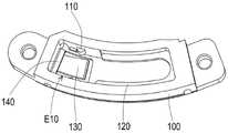
滑轨100配置于顶部52T,并具有一入口E10(标示于图3)与相邻至入口E10的一限位部120。握带200可拆卸地组装至滑轨100以及控制手把52的底部52B。握带200包括一带体220及一金属件210。金属件210组装至带体的一端。金属件210具有一滑块212(标示于图4)。滑块212适于沿着一方向D12可拆卸地经由入口E10组装至滑轨100。滑块212适于沿着限位部120(标示于图3)移动。限位部120限制滑块212沿着方向D12的移动。The
根据上述,在本实施例的手把总成50中,使用者只要推动金属件210即可让金属件210在滑轨100内移动,进而改变握带200与控制手把52之间的连接位置。当用户觉得按压按键不方便时,只要进行单一方向的动作就可以调整改变握带200与控制手把52的连接位置,使不同手掌大小的使用者都能得到良好的使用体验。According to the above, in the
本实施例中,控制手把52具有一控制面板52P,滑轨100的开口P10位于控制面板52P。换言之,滑轨100是安装在控制面板52P下方。在其他实施例中,滑轨100也可以暴露在控制面板52P外,但本发明不对此加以限制。此外,控制面板52P上也可以配置多个按键或是触摸板。In this embodiment, the
本实施例中,金属件210可拆卸地卡置于滑轨100,但本发明不对此加以限制。采用此设计,使用者不仅可以选用自己喜爱的握带200,也方便对握带200进行必要的清洁。金属件210包括滑块210A、连接部210B与固定部210C(标示于图7)。固定部210C用于使金属件210固接至握带200的带体220,而连接部210B连接滑块210A与固定部210C。本实施例中,握带200还包括一系绳230,可拆卸地组装至控制手把52的底部52B,并耦接至带体220。In this embodiment, the
图2是图1的手把总成的握带与滑轨的连接处的示意图。图3是将图2中的金属件移除后的示意图。请参照图2与图3,本实施例中,滑轨100具有一入口E10,而图3中就显示金属件210位于入口E10的状态。本实施例的金属件210是以单一组件的型态的扣件呈现,并与握带200的其他部分连接,但本发明不对此加以限制。本实施例的握带200的主要材质是泡棉。以泡棉为主要材质的握带200可以大致维持形状,以方便在穿戴的过程中确保提供弧形的空间供使用者的手掌穿过。FIG. 2 is a schematic diagram of the connection between the grip belt and the slide rail of the handlebar assembly of FIG. 1 . FIG. 3 is a schematic view after the metal parts in FIG. 2 are removed. Referring to FIG. 2 and FIG. 3 , in this embodiment, the
图4是图2的剖视图。请参照图3与图4,本实施例中,滑轨100的侧壁具有多个第一定位结构110,金属件210具有一第二定位结构212,第二定位结构212用于卡合些第一定位结构110其中之一。以本实施例而,共有4组第一定位结构110位于不同的四个位置,因此金属件210可以被适当地卡置在这四个位置的其中之一而不会轻易离开。在本实施例中,第一定位结构110为凸肋、而第二定位结构212为凹槽。在其他实施例中,第一定位结构110与第二定位结构212也可以是结构上能相配合的结构设计。FIG. 4 is a cross-sectional view of FIG. 2 . Referring to FIGS. 3 and 4 , in this embodiment, the side wall of the
图5是图2的金属件移至另一位置后的示意图。图6是图5的剖视图。图7是图5的另一方向的剖视图。请参照图3、图5与图7,本实施例中,滑轨100具有一限位部120。限位部120延伸于滑轨100的除了入口E10以外的部分的侧壁上。金属件210具有一限位结构214。限位结构214用于卡合限位部120而避免金属件210脱离滑轨100。从图3可以看出,限位部120并没有延伸至入口E10,因此不会妨碍金属件210从入口E10进入滑轨100。当金属件210从入口E10往旁边滑移时,金属件210的限位结构214会卡合限位部120。此时,金属件210受到限位部120的限位而只能在滑轨100内滑动,但无法在有限位部120的位置以垂直于滑动方向的方向脱离滑轨100。图6中也可看出,金属件210被另一组第一定位结构110卡置而保持在与图4不同的位置且无法轻易离开。在本实施例中,限位部120为凸肋、而限位结构214为凹槽。在其他实施例中,限位部120与限位结构214也可以是结构上能相配合的结构设计。FIG. 5 is a schematic view of the metal piece of FIG. 2 after being moved to another position. FIG. 6 is a cross-sectional view of FIG. 5 . FIG. 7 is a cross-sectional view in another direction of FIG. 5 . Referring to FIG. 3 , FIG. 5 and FIG. 7 , in this embodiment, the
图8是图5的再一方向的剖视图。请参照图4、图6与图8,本实施例中,滑轨100具有一弹片130。弹片130位于滑轨100的底部并对应于入口E10,例如位于入口E10的底壁上。金属件210进入入口E10时,弹片130受压变形,如图4。金属件210进入滑轨100并离开入口E10后,弹片130复位并用于避免金属件210的滑块210A进入入口E10,如图6与图8。换言之,金属件210要从如图8所示的位置往入口E10移动时,弹片130会抵住金属件210而不让其往入口E10移动。因此,金属件210从入口E10进入滑轨100后,无法再度往入口E10移动,也就不会有轻易脱离滑轨100的问题。若要让金属件210脱离滑轨100,则必须推动金属件210至压下按压弹片130才能允许金属件210进入入口E10并脱离滑轨100。FIG. 8 is a cross-sectional view taken in another direction of FIG. 5 . Please refer to FIG. 4 , FIG. 6 and FIG. 8 , in this embodiment, the
请再参照图4与图8,本实施例中,滑轨100具有一第一单向卡榫140。第一单向卡榫140与该限位部120分别位于入口E10的两侧。第一单向卡榫140位于入口E10的侧壁上。金属件210的滑块210A具有一第二单向卡榫216。第一单向卡榫140用于与第二单向卡榫216配合。当金属件210从入口E10进入滑轨100时,只要稍加施力就可让第二单向卡榫216通过第一单向卡榫140。并且,当第二单向卡榫216通过第一单向卡榫140后,即使金属件210尚未向旁边滑移而受到限位部120的限位,第一单向卡榫140仍然会卡住第二单向卡榫216,使得金属件210无法沿着方向D12移动而轻易脱离滑轨100。当然,当施加较大的力量时,仍可让金属件210克服第一单向卡榫140的限制而脱离滑轨100。Please refer to FIG. 4 and FIG. 8 again. In this embodiment, the
图9是图2的金属件移至再一位置后的示意图。图10是图9的剖视图。请参照图9与图10,金属件210也可从图8所示的位置继续滑移至图9与图10所示的位置。当使用者只要用拇指推动金属件210就可以调整改变握带200与控制手把52的连接位置,以符合使不同手掌大小的使用者。此外,用拇指持续推动金属件210至入口E10即可解锁,以便于取下握带200。FIG. 9 is a schematic view of the metal part of FIG. 2 after moving to another position. FIG. 10 is a cross-sectional view of FIG. 9 . Referring to FIGS. 9 and 10 , the
综上所述,在本发明的手把总成中,握带是通过滑轨而连接于控制手把,故两者的连接位置可调,以符合不同手掌大小的使用者。将金属件推动至滑轨内的入口即可解锁,以便于取下握带,因此无论是解锁或是调整金属件的位置均可以用拇指推动金属件沿着滑轨内移动而达成,具有较佳的操作便利性。To sum up, in the handle assembly of the present invention, the grip belt is connected to the control handle through the slide rail, so the connection position of the two can be adjusted to suit users with different palm sizes. Push the metal piece to the entrance in the slide rail to unlock, so that the grip belt can be easily removed. Therefore, whether to unlock or adjust the position of the metal piece, you can use your thumb to push the metal piece to move along the slide rail. Excellent operational convenience.
最后应说明的是:以上各实施例仅用以说明本发明的技术方案,而非对其限制;尽管参照前述各实施例对本发明进行了详细的说明,本领域的普通技术人员应当理解:其依然可以对前述各实施例所记载的技术方案进行修改,或者对其中部分或者全部技术特征进行等同替换;而这些修改或者替换,并不使相应技术方案的本质脱离本发明各实施例技术方案的范围。Finally, it should be noted that the above embodiments are only used to illustrate the technical solutions of the present invention, but not to limit them; although the present invention has been described in detail with reference to the foregoing embodiments, those of ordinary skill in the art should understand that: The technical solutions described in the foregoing embodiments can still be modified, or some or all of the technical features thereof can be equivalently replaced; and these modifications or replacements do not make the essence of the corresponding technical solutions deviate from the technical solutions of the embodiments of the present invention. scope.
Claims (7)
Translated fromChineseApplications Claiming Priority (2)
| Application Number | Priority Date | Filing Date | Title |
|---|---|---|---|
| US202063108876P | 2020-11-03 | 2020-11-03 | |
| US63/108,876 | 2020-11-03 |
Publications (2)
| Publication Number | Publication Date |
|---|---|
| CN114442800Atrue CN114442800A (en) | 2022-05-06 |
| CN114442800B CN114442800B (en) | 2023-10-13 |
Family
ID=81362670
Family Applications (1)
| Application Number | Title | Priority Date | Filing Date |
|---|---|---|---|
| CN202111073321.0AActiveCN114442800B (en) | 2020-11-03 | 2021-09-14 | Handlebar assembly |
Country Status (3)
| Country | Link |
|---|---|
| US (1) | US12011670B2 (en) |
| CN (1) | CN114442800B (en) |
| TW (1) | TWI779829B (en) |
Families Citing this family (1)
| Publication number | Priority date | Publication date | Assignee | Title |
|---|---|---|---|---|
| AU2023436706A1 (en)* | 2023-03-16 | 2025-09-25 | Razer (Asia-Pacific) Pte. Ltd. | Controller |
Citations (6)
| Publication number | Priority date | Publication date | Assignee | Title |
|---|---|---|---|---|
| JPH05130472A (en)* | 1991-10-21 | 1993-05-25 | Matsushita Electric Ind Co Ltd | Grip for camcorder |
| JP2003111902A (en)* | 2001-10-04 | 2003-04-15 | Pioneer Electronic Corp | Hand-placing device |
| US20060075605A1 (en)* | 2002-08-02 | 2006-04-13 | Mike Lagaly | Adjustable grasping assembly for tools |
| DE202018004060U1 (en)* | 2018-08-31 | 2018-09-17 | Gerd Eisenblätter Gmbh | Handle for a hand tool |
| CN208922524U (en)* | 2018-04-12 | 2019-05-31 | 广州运筹网络科技有限公司 | A kind of VR training device of passenger stock safe escape |
| US20190232160A1 (en)* | 2016-10-11 | 2019-08-01 | Valve Corporation | Electronic controller with finger sensing and an adjustable hand retainer |
Family Cites Families (4)
| Publication number | Priority date | Publication date | Assignee | Title |
|---|---|---|---|---|
| US10898797B2 (en) | 2016-10-11 | 2021-01-26 | Valve Corporation | Electronic controller with finger sensing and an adjustable hand retainer |
| US10209738B1 (en) | 2017-05-04 | 2019-02-19 | Facebook Technologies, Llc | Apparatus, system, and method for adjusting head-mounted-display straps |
| CN209765445U (en) | 2019-06-19 | 2019-12-10 | 广州新维感信息技术有限公司 | VR handle convenient to take and can inhale sweat |
| US12001171B2 (en)* | 2020-04-24 | 2024-06-04 | Meta Platforms Technologies, Llc | Electronic system and related devices and methods |
- 2021
- 2021-09-14USUS17/474,062patent/US12011670B2/enactiveActive
- 2021-09-14TWTW110134151Apatent/TWI779829B/enactive
- 2021-09-14CNCN202111073321.0Apatent/CN114442800B/enactiveActive
Patent Citations (6)
| Publication number | Priority date | Publication date | Assignee | Title |
|---|---|---|---|---|
| JPH05130472A (en)* | 1991-10-21 | 1993-05-25 | Matsushita Electric Ind Co Ltd | Grip for camcorder |
| JP2003111902A (en)* | 2001-10-04 | 2003-04-15 | Pioneer Electronic Corp | Hand-placing device |
| US20060075605A1 (en)* | 2002-08-02 | 2006-04-13 | Mike Lagaly | Adjustable grasping assembly for tools |
| US20190232160A1 (en)* | 2016-10-11 | 2019-08-01 | Valve Corporation | Electronic controller with finger sensing and an adjustable hand retainer |
| CN208922524U (en)* | 2018-04-12 | 2019-05-31 | 广州运筹网络科技有限公司 | A kind of VR training device of passenger stock safe escape |
| DE202018004060U1 (en)* | 2018-08-31 | 2018-09-17 | Gerd Eisenblätter Gmbh | Handle for a hand tool |
Also Published As
| Publication number | Publication date |
|---|---|
| TW202223597A (en) | 2022-06-16 |
| US20220134240A1 (en) | 2022-05-05 |
| CN114442800B (en) | 2023-10-13 |
| TWI779829B (en) | 2022-10-01 |
| US12011670B2 (en) | 2024-06-18 |
Similar Documents
| Publication | Publication Date | Title |
|---|---|---|
| CN100572163C (en) | Child restraint assemblies for child vehicle seats | |
| US6624806B2 (en) | Joystick capable of controlling direction rudder and accelerator synchronously | |
| US20060179899A1 (en) | Cable lock | |
| JPH09503968A (en) | Palm rest for use with computer data entry devices | |
| US7020905B2 (en) | Swimming goggle | |
| US6147673A (en) | Computer input device and keyboard | |
| US9028006B2 (en) | Safety bow assembly and child seat including the same | |
| TWI779829B (en) | Hand controller assembly | |
| US20070018959A1 (en) | Mouse interface system capable of providing thermal feedback | |
| JP3131951U (en) | PC mouse with adjustable external shape | |
| EP1440366A1 (en) | A portable data input device and use of such a device | |
| US6549189B1 (en) | Method for operating a computer input device and keyboard | |
| CN110088713B (en) | Input device | |
| US7071921B2 (en) | Ergonomic mouse | |
| US7133021B2 (en) | Finger-fitting pointing device | |
| US20170075438A1 (en) | Computer mouse having interchangeable modules adaptable to left/right hand use | |
| TW202026821A (en) | Mouse having a movable palm-rest | |
| EP1166200B1 (en) | An actuator device for a personal computer | |
| US20190278326A1 (en) | Electronic device and expansion electronic system | |
| US9588682B2 (en) | Thumb operated keyboard device | |
| CN111381690B (en) | Mouse with movable luminous structure | |
| US20040196263A1 (en) | Mouse | |
| US20050174330A1 (en) | Computer input devices | |
| US11119586B2 (en) | Adjustable pointing devices | |
| KR101136096B1 (en) | Key button division cover for a virtual keyboard |
Legal Events
| Date | Code | Title | Description |
|---|---|---|---|
| PB01 | Publication | ||
| PB01 | Publication | ||
| SE01 | Entry into force of request for substantive examination | ||
| SE01 | Entry into force of request for substantive examination | ||
| GR01 | Patent grant | ||
| GR01 | Patent grant |