CN114431921A - Ultrasonic scalpel and its blade - Google Patents
Ultrasonic scalpel and its bladeDownload PDFInfo
- Publication number
- CN114431921A CN114431921ACN202210102850.7ACN202210102850ACN114431921ACN 114431921 ACN114431921 ACN 114431921ACN 202210102850 ACN202210102850 ACN 202210102850ACN 114431921 ACN114431921 ACN 114431921A
- Authority
- CN
- China
- Prior art keywords
- blade
- ultrasonic
- row
- sawtooth
- rows
- Prior art date
- Legal status (The legal status is an assumption and is not a legal conclusion. Google has not performed a legal analysis and makes no representation as to the accuracy of the status listed.)
- Pending
Links
Images


Classifications
- A—HUMAN NECESSITIES
- A61—MEDICAL OR VETERINARY SCIENCE; HYGIENE
- A61B—DIAGNOSIS; SURGERY; IDENTIFICATION
- A61B17/00—Surgical instruments, devices or methods
- A61B17/14—Surgical saws
- A61B17/149—Chain, wire or band saws
- A—HUMAN NECESSITIES
- A61—MEDICAL OR VETERINARY SCIENCE; HYGIENE
- A61B—DIAGNOSIS; SURGERY; IDENTIFICATION
- A61B17/00—Surgical instruments, devices or methods
- A61B17/32—Surgical cutting instruments
- A61B17/320068—Surgical cutting instruments using mechanical vibrations, e.g. ultrasonic
Landscapes
- Health & Medical Sciences (AREA)
- Surgery (AREA)
- Life Sciences & Earth Sciences (AREA)
- Engineering & Computer Science (AREA)
- Heart & Thoracic Surgery (AREA)
- Animal Behavior & Ethology (AREA)
- Veterinary Medicine (AREA)
- Biomedical Technology (AREA)
- Dentistry (AREA)
- Medical Informatics (AREA)
- Molecular Biology (AREA)
- Nuclear Medicine, Radiotherapy & Molecular Imaging (AREA)
- General Health & Medical Sciences (AREA)
- Public Health (AREA)
- Oral & Maxillofacial Surgery (AREA)
- Mechanical Engineering (AREA)
- Dental Tools And Instruments Or Auxiliary Dental Instruments (AREA)
- Surgical Instruments (AREA)
Abstract
Description
Translated fromChinese技术领域technical field
本发明涉及手术器械技术领域,具体地涉及一种超声手术刀及其刀头。The invention relates to the technical field of surgical instruments, in particular to an ultrasonic scalpel and a blade head thereof.
背景技术Background technique
随着现代医学的迅猛发展,超声手术仪器已越来越多地应用于临床外科手术治疗中,它将超声能量应用于外科手术,具有切割精细、安全、组织选择性和低温止血等特点,极大地丰富了外科手术的手段,提升了外科手术的质量,一定程度上减轻了患者的病痛。其中,超声手术刀就是一种具有特定应用功能的超声手术仪器。With the rapid development of modern medicine, ultrasonic surgical instruments have been increasingly used in clinical surgical treatment. It applies ultrasonic energy to surgical operations. It has the characteristics of fine cutting, safety, tissue selectivity and low temperature hemostasis. The earth has enriched the means of surgery, improved the quality of surgery, and relieved the pain of patients to a certain extent. Among them, the ultrasonic scalpel is an ultrasonic surgical instrument with specific application functions.
目前的超声手术刀一般分为两种形式,如美国专利US8343178所揭示的一种超声手术刀,位于远端的工作头为光滑的刀刃结构,即该专利中揭示的附图标记20、22、24揭示的部分,该刀刃结构包括远端刀刃和位于其两侧的侧面刀刃,远端刀刃与侧面刀刃圆滑过渡。这种形式的刀刃结构的切割效率不高。The current ultrasonic scalpel is generally divided into two forms, such as an ultrasonic scalpel disclosed in US Pat. No. 8,343,178. The working head at the distal end is a smooth blade structure, namely the
因此,美国专利USD667117揭示了另一种超声手术刀的刀刃结构,远端的刀刃采用刀片形式,刀刃的两侧采用正三角形锯齿形式。这样就可以增加超声手术刀的手术使用场景,正三角形锯齿可以切割相对较硬的骨头或其他组织。但是由于存在超声高频振荡产生的高内应力的存在,无法在锯齿造型上做的如传统行业那般形状激进,齿形深且锋利。为了协调锯齿内应力和切割效率,欧洲专利EP3586774揭示了另一种超声手术刀的切割刀刃。Therefore, US Patent USD667117 discloses another blade structure of an ultrasonic scalpel. The distal blade is in the form of a blade, and the two sides of the blade are in the form of regular triangular serrations. In this way, the surgical use of the ultrasonic scalpel can be increased, and the equilateral triangular serrations can cut relatively hard bones or other tissues. However, due to the existence of high internal stress generated by ultrasonic high-frequency oscillation, it is impossible to make the shape of the sawtooth as radical as the traditional industry, and the tooth shape is deep and sharp. In order to coordinate the internal stress of the saw teeth and the cutting efficiency, European patent EP3586774 discloses another cutting edge of an ultrasonic scalpel.
发明内容SUMMARY OF THE INVENTION
本发明的目的是克服现有技术存在的不足,提供一种高效切割的超声手术刀及其刀头。The purpose of the present invention is to overcome the deficiencies existing in the prior art, and to provide an ultrasonic scalpel for efficient cutting and a cutter head thereof.
本发明的目的通过以下技术方案来实现:The object of the present invention is achieved through the following technical solutions:
一种超声手术刀,包括圆柱形的主体,所述主体的近端为一连接结构,远端设置有刀头,所述刀头包括位于最远端的刀刃和至少位于其一侧沿主体轴线延伸设置的锯齿排,所述锯齿排为并排的两列,每列锯齿排均由一列锯齿排列而成,两列所述锯齿排的齿尖的朝向相反。An ultrasonic scalpel comprises a cylindrical main body, the proximal end of the main body is a connecting structure, the distal end is provided with a cutter head, the cutter head comprises a cutting edge located at the most distal end and at least one side of the main body along the axis of the main body The extended sawtooth rows are arranged in two parallel rows, each row of sawtooth rows is formed by one row of sawtooth rows, and the tooth tips of the two rows of the sawtooth rows are in opposite directions.
优选的,所述锯齿的前角γ为正前角。Preferably, the rake angle γ of the saw teeth is a positive rake angle.
优选的,所述锯齿的前角γ为15°±5°。Preferably, the rake angle γ of the saw teeth is 15°±5°.
优选的,所述锯齿的后角α为20°±10°。Preferably, the relief angle α of the saw teeth is 20°±10°.
优选的,所述锯齿的齿尖角β不小于45°。Preferably, the tooth tip angle β of the saw teeth is not less than 45°.
优选的,所述锯齿排的锯齿齿间距为1.3mm至1.7mm之间。Preferably, the tooth pitch of the saw tooth row is between 1.3 mm and 1.7 mm.
优选的,两列所述锯齿排中相应的锯齿的齿根在超声手术刀厚度方向为相互重叠的共齿底结构。Preferably, the tooth roots of the corresponding serrations in the two serration rows are mutually overlapping common tooth bottom structures in the thickness direction of the ultrasonic scalpel.
优选的,所述超声手术刀在厚度方向分别具有两个端面,至少一个所述端面上开设有凹槽。Preferably, the ultrasonic scalpel has two end faces in the thickness direction, and at least one of the end faces is provided with a groove.
优选的,所述刀刃为刃口刀刃,钝口刀刃,及锯齿刀刃的至少一种。Preferably, the blade is at least one of an edge blade, a blunt blade, and a serrated blade.
优选的,所述刀头包括位于最远端的刀刃和分别对称设于其两侧沿主体轴线延伸设置的两条锯齿排。Preferably, the cutting head comprises a cutting edge located at the most distal end and two serration rows symmetrically arranged on both sides thereof and extending along the axis of the main body.
优选的,所述刀头包括位于最远端的刀刃和位于其一侧沿主体轴线延伸设置的锯齿排,以及位于其对称的另一侧的切割刃。Preferably, the cutting head comprises a cutting edge located at the most distal end and a serration row located on one side thereof extending along the axis of the main body, and a cutting edge located on the other symmetrical side thereof.
本发明还揭示了一种超声手术刀的刀头,所述刀头包括位于最远端的刀刃和至少位于其一侧沿主体轴线延伸设置的锯齿排,所述锯齿排包括锯齿,所述锯齿为龟背齿,其前角γ为15°±5°,后角α为20°±10°。The invention also discloses a cutter head of an ultrasonic scalpel. The cutter head includes a cutting edge located at the most distal end and a serration row extending along the axis of the main body at least on one side of the cutter head. The serration row comprises serrations, and the serrations are It is the dorsal tooth of the turtle, its front angle γ is 15°±5°, and the back angle α is 20°±10°.
优选的,所述锯齿排为并排的两列,每列锯齿排均由一列所述锯齿排列而成,两列所述锯齿排的齿尖的朝向相反。Preferably, the sawtooth rows are two side-by-side rows, each row of sawtooth rows is formed by one row of the sawtooth rows, and the tooth tips of the two rows of sawtooth rows are oriented in opposite directions.
优选的,所述锯齿的齿尖角β不小于45°。Preferably, the tooth tip angle β of the saw teeth is not less than 45°.
优选的,所述锯齿排的锯齿齿间距为1.3mm至1.7mm之间。Preferably, the tooth pitch of the saw tooth row is between 1.3 mm and 1.7 mm.
优选的,两列所述锯齿排中相应的锯齿的齿根在超声手术刀厚度方向为相互重叠的共齿底结构。Preferably, the tooth roots of the corresponding serrations in the two serration rows are mutually overlapping common tooth bottom structures in the thickness direction of the ultrasonic scalpel.
优选的,所述超声手术刀在厚度方向分别具有两个端面,至少一个所述端面上开设有凹槽。Preferably, the ultrasonic scalpel has two end faces in the thickness direction, and at least one of the end faces is provided with a groove.
优选的,所述刀刃为刃口刀刃,钝口刀刃,及锯齿刀刃的至少一种。Preferably, the blade is at least one of an edge blade, a blunt blade, and a serrated blade.
优选的,所述刀头包括位于最远端的刀刃和分别对称设于其两侧沿主体轴线延伸设置的两条锯齿排。Preferably, the cutting head comprises a cutting edge located at the most distal end and two serration rows symmetrically arranged on both sides thereof and extending along the axis of the main body.
优选的,所述刀头包括位于最远端的刀刃和位于其一侧沿主体轴线延伸设置的锯齿排,以及位于其对称的另一侧的切割刃。Preferably, the cutting head comprises a cutting edge located at the most distal end and a serration row located on one side thereof extending along the axis of the main body, and a cutting edge located on the other symmetrical side thereof.
本发明的有益效果主要体现在:The beneficial effects of the present invention are mainly reflected in:
双排反向布局的勾齿结构设计,保证在整个周期都有足够的切削力,可以在不增加应力值的前提下成倍的提高切割效率,降低对主机的功率输出需求;The double-row reverse layout of the hook tooth structure design ensures that there is enough cutting force in the whole cycle, which can double the cutting efficiency without increasing the stress value and reduce the power output demand of the host;
切削过程中刀头可以很好地与负载进行耦合,操作者仅需扶住刀具进行切割即可,提高了使用过程的舒适程度;During the cutting process, the cutter head can be well coupled with the load, and the operator only needs to hold the cutter for cutting, which improves the comfort of the use process;
刀头的一侧设置有锯齿排,其对称的另一侧设置有切割刃,操作者可以有选择地选用锯齿排或者切割刃进行切割,扩大了本发明的使用场景。One side of the cutter head is provided with a serrated row, and the other symmetrical side is provided with a cutting edge, and the operator can selectively select the serrated row or the cutting edge for cutting, which expands the application scene of the present invention.
附图说明Description of drawings
下面结合附图对本发明技术方案作进一步说明:The technical scheme of the present invention will be further described below in conjunction with the accompanying drawings:
图1:本发明超声手术刀优选实施例的示意图;Fig. 1: the schematic diagram of the preferred embodiment of the ultrasonic scalpel of the present invention;
图2:图1中A部分的放大图;Figure 2: Enlarged view of part A in Figure 1;
图3:图2的正视图;Figure 3: Front view of Figure 2;
图4:图2的俯视图;Figure 4: Top view of Figure 2;
图5:超声波的特性示意图;Figure 5: Schematic diagram of the characteristics of ultrasonic waves;
图6:三种齿形的切削力的对比示意图;Figure 6: Schematic diagram of the comparison of the cutting forces of the three tooth profiles;
图7:前角与切削力的对比示意图;Figure 7: Schematic diagram of the comparison of rake angle and cutting force;
图8:两种齿背形状的对比示意图;Figure 8: Schematic diagram of the comparison of two tooth back shapes;
图9:本发明优选实施例的龟背齿的排列示意图;Fig. 9: the arrangement schematic diagram of the tortoise teeth of the preferred embodiment of the present invention;
图10:本发明超声手术刀第二实施例的刀头的示意图;Fig. 10: A schematic diagram of the cutter head of the second embodiment of the ultrasonic scalpel of the present invention;
图11:本发明超声手术刀第三实施例的刀头的示意图;Figure 11: a schematic diagram of the cutter head of the third embodiment of the ultrasonic scalpel of the present invention;
图12:本发明超声手术刀第三实施例的刀头的另一方向的示意图;Fig. 12: a schematic diagram of another direction of the cutter head of the third embodiment of the ultrasonic scalpel of the present invention;
图13:本发明超声手术刀第四实施例的刀头的示意图;Figure 13: A schematic diagram of the blade head of the fourth embodiment of the ultrasonic scalpel of the present invention;
图14:本发明超声手术刀第五实施例的刀头的示意图;Figure 14: a schematic diagram of the blade head of the fifth embodiment of the ultrasonic scalpel of the present invention;
图15:本发明超声手术刀第六实施例的刀头的示意图。Fig. 15 is a schematic diagram of the cutter head of the sixth embodiment of the ultrasonic scalpel of the present invention.
具体实施方式Detailed ways
以下将结合附图所示的具体实施方式对本发明进行详细描述。但这些实施方式并不限于本发明,本领域的普通技术人员根据这些实施方式所做出的结构、方法、或功能上的变换均包含在本发明的保护范围内。The present invention will be described in detail below with reference to the specific embodiments shown in the accompanying drawings. However, these embodiments are not limited to the present invention, and structural, method, or functional transformations made by those of ordinary skill in the art based on these embodiments are all included in the protection scope of the present invention.
在方案的描述中,需要说明的是,术语“中心”、“上”、“下”、“左”、“右”、“前”、“后”、“竖直”、“水平”、“内”、“外”等指示的方位或位置关系为基于附图所示的方位或位置关系,仅是为了便于描述和简化描述,而不是指示或暗示所指的装置或元件必须具有特定的方位、以特定的方位构造和操作,因此不能理解为对本发明的限制。此外,术语“第一”、“第二”、“第三”仅用于描述目的,而不能理解为指示或暗示相对重要性。并且,在方案的描述中,以操作人员为参照,靠近操作者的方向为近端,远离操作者的方向为远端。In the description of the scheme, it should be noted that the terms "center", "upper", "lower", "left", "right", "front", "rear", "vertical", "horizontal", " The orientation or positional relationship indicated by "inside", "outside", etc. is based on the orientation or positional relationship shown in the drawings, which is only for convenience and simplification of description, rather than indicating or implying that the indicated device or element must have a specific orientation , constructed and operated in a specific orientation, and therefore should not be construed as limiting the invention. Furthermore, the terms "first", "second", and "third" are used for descriptive purposes only and should not be construed to indicate or imply relative importance. In addition, in the description of the solution, with reference to the operator, the direction close to the operator is the proximal end, and the direction away from the operator is the distal end.
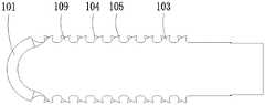
如图1所示,本发明揭示了一种超声手术刀,包括圆柱形的主体111。主体111可以是同一直径的圆柱体,也可以是适应超声能量传输的多节式不同直径的圆柱体。As shown in FIG. 1 , the present invention discloses an ultrasonic scalpel, which includes a
所述主体111的近端为一连接结构112,所述连接结构112可以是内螺纹,外螺纹,粘接或者超声焊接等方式,与超声发生器连接。The proximal end of the
所述主体111的远端设置有刀头113。具体如图2至图4所示,所述刀头113包括位于最远端的刀刃101和至少位于其一侧沿主体轴线延伸设置的锯齿排102。本领域的技术人员所熟知的,锯齿排102可以设置在刀头113的任意一侧,当然也可以是图2中揭示的分别对称设于刀刃101的两侧的两条锯齿排102。The distal end of the
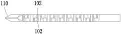
所述刀头113为本发明的设计要点,如图1至图4所示的优选实施例中,所述刀头113的刀刃101为薄片式渐变的刃口刀刃,具体为:沿超声手术刀厚度方向为圆弧形投影,沿超声手术刀宽度方向为三角形投影110。沿厚度方向为半圆的结构设计,该结构较为圆滑,当刀刃101接触到血管、神经等脆弱组织时,不会对其产生刮伤,且超声的作用会将其推远,再配合足够的冷却水降低热效应,可以对这些组织产生很好的保护效果。沿宽度方向为三角形设计,尖部可以设置有一小平面或者圆弧面,在接触到松质骨及较薄的皮质骨时,锐角角度的尖顶也能对这些组织实现较有效的切割。The
所述刀刃101的半圆弧状顶部结束的两侧末梢各有一个齿尖,该齿尖由两个圆弧段相交成形,形成第一齿尖114。该第一齿尖114由尖端外圆R3mm和内圆R1.5mm组合而成,沿齿尖做切线,可以看出该齿属于-15°±5°的负前角,保证整个刀刃101属于以切为辅,以安全为主的尖端面,减少术中对医生操作精度的要求,更好的保护重要组织。The two ends of the semi-circular arc top of the
所述锯齿排102为并排的两列,每列锯齿排102均由一列锯齿103排列而成,本优选实施例中两列所述锯齿排102的锯齿103完全相同。The
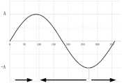
对于锯齿103来讲,它的运动轨迹为理想简谐振动,如图5所示,从平衡位置零点开始启动,对于正半周,齿尖朝刀头远端行进;对于负半周,朝刀头近端行进。为了保证刀头在正半周和负半周都有相近的切割效果,本发明两列所述锯齿排102的齿尖104、105的朝向相反。For the sawtooth 103, its motion trajectory is an ideal simple harmonic vibration. As shown in Figure 5, it starts from the zero point of the equilibrium position. For the positive half cycle, the tooth tip travels toward the distal end of the cutter head; for the negative half cycle, it moves closer to the cutter head. end travel. In order to ensure that the cutter head has similar cutting effects in the positive half circle and the negative half circle, the
对于锯齿形状来说,有三个重要参数,分别是:For the sawtooth shape, there are three important parameters, namely:
γ:前角122,切削前刀面与垂直平面的夹角;γ:
α:后角120,切削面与水平面的夹角;α: The clearance angle is 120, the angle between the cutting surface and the horizontal plane;
β:齿尖角121,前刀面与后刀面所形成的夹角。β:
如图6所示的三种齿形,分别为标准齿117(前角为0°),钝齿118(前角为-15°±5°),勾齿119(前角为+15°±5°)。传统的锯齿为等腰三角形齿形,前角γ为负值,属于钝齿118。虽然在运动的正负半周都有相同的效果;但缺点也同样明显,切割效率不足。The three tooth shapes shown in Figure 6 are standard tooth 117 (rake angle is 0°), obtuse tooth 118 (rake angle is -15°±5°), hook tooth 119 (rake angle is +15°±5°) 5°). The traditional sawtooth is an isosceles triangular tooth shape, and the front angle γ is a negative value, which belongs to the
具体参照图6,对切削行进过程中的刀具受到的切削力进行分析。可以看到,钝齿118的切削力最大,勾齿119的切削力最小,但钝齿有较大的偏离切削面的力Fz,而勾齿的偏离切削面的力Fz为负值。说明传统的等腰三角形锯齿在使用过程中,产生较大的行进切削力,但切削过程中刀头容易被弹开,需要足够大的按压力来稳定刀头。本发明中采用的是勾齿119,即所述锯齿103的前角γ122为正前角。虽然行进切削力仅为钝齿的68%左右,对于相同难度的负载,明显切削效果会更好;且偏离切削面的力Fz为负值,说明切削过程中刀头可以很好地与负载进行耦合,操作者仅需扶住刀具进行切割即可,提高了使用过程的舒适程度。Referring specifically to FIG. 6 , the cutting force received by the tool during the cutting process is analyzed. It can be seen that the cutting force of the
为了确定正前角的角度,如图7所示,本发明分别从0度开始至30度均匀设置7种正前角的角度,发现随着正前角角度的加大,行进切削力逐渐下降,在10°开始出现负值的按压力Fz。且随着前角角度的增加,切削力下降的幅度也逐渐放缓。再对这7组齿形的刀头进行模态分析,在设计的工作频率,分析统计最大应力stress的数值,整体应力变化比较小,但也可以看出随着前角角度的增加,应力值先下降后上升,在10°至20°±10°的前角角度附近为最小值。随后,正前角角度增加,最大应力逐渐增加。而且正前角角度的增加,势必会造成齿尖角变小,切削齿尖的强度下降,更容易发生切削疲劳导致齿尖破裂。综上所述,在10°至20°±10°之间的正前角角度设计是合适的,本发明采用的是最优的为15°±5°的正前角γ122。In order to determine the angle of the positive rake angle, as shown in FIG. 7 , the present invention evenly sets 7 kinds of positive rake angle angles from 0 degrees to 30 degrees, and it is found that with the increase of the positive rake angle angle, the traveling cutting force gradually decreases , a negative pressing force Fz begins to appear at 10°. And with the increase of the rake angle, the reduction of the cutting force gradually slowed down. Then carry out modal analysis on the cutter heads of the 7 groups of tooth profiles. At the designed operating frequency, the value of the maximum stress stress is analyzed and counted. The overall stress change is relatively small, but it can also be seen that with the increase of the rake angle, the stress value It first falls and then rises, and the minimum value is around the rake angle of 10° to 20°±10°. Subsequently, the positive rake angle increases and the maximum stress increases gradually. Moreover, the increase of the positive rake angle will inevitably cause the tooth tip angle to become smaller, the strength of the cutting tooth tip will decrease, and it is more likely to cause cutting fatigue and lead to tooth tip cracking. To sum up, the design of the positive rake angle between 10° and 20°±10° is suitable, and the optimal positive rake angle γ122 of 15°±5° is adopted in the present invention.
如图8所示,按照齿背的形状来分,常见的有直背齿123和龟背齿124,本发明采用的是龟背齿124。因为相同前后角的前提下,龟背齿可以有更窄的齿宽,对于齿尖的强度和齿间距的设计有明显的优势。采用如前文相同的方法进行建模分析,我们对后角的大小进行了分析,分别从0°至30°均匀设置7种后角参数(忽略后背与负载的摩擦影响),对切削力进行分析,我们发现随着后角角度的增加,行进切削力有微弱增加的趋势。仅从切削力的角度上来看,后角角度越小越好。但后角角度越小,齿背更容易与剩余的负载组织进行接触,从而增加阻力和摩擦生热;从形态上看,后角角度越小,齿间距就会越大,单位距离内可以放置的齿数会越少,反而切削效果会下降。综合考虑,所以本发明中优选的后角角度为20°±10°。所述锯齿103的齿尖角β121的角度不小于45°。本发明优选齿尖角β121的角度为55°。As shown in FIG. 8 , according to the shape of the dorsum of the teeth, the common ones are straight
如图9所示,按照正前角15°±5°,后角20°±10°设计的龟背齿,齿根圆角R0.25,齿高0.6mm,最短的齿间距为1.05mm。在尽量保证总切割长度相当的前提下,分别按照齿间距125×齿数126:1.1mm×13,1.3mm×11,1.5mm×10,1.7mm×8设计四种不同的齿间距。在本发明设计的谐振频率点分析最大高频内应力,最大应力总是位于最近端齿的根部,随着间距的增加,最大应力逐渐减小,在间距增加到1.5mm后应力减小的值就比较微弱,这时候最大应力主要受最近端齿的位置决定,齿离第一节点距离越近,应力值越高。在总长不变的前提下,取1.3mm至1.7mm是比较合理的选择区间,其中1.5mm齿间距是一个比较优的值。As shown in Figure 9, the tortoise teeth designed according to the positive rake angle of 15°±5° and the back angle of 20°±10°, the root fillet is R0.25, the tooth height is 0.6mm, and the shortest tooth spacing is 1.05mm. Under the premise of ensuring the total cutting length as much as possible, four different tooth spacings are designed according to the tooth spacing 125×the number of teeth 126: 1.1mm×13, 1.3mm×11, 1.5mm×10, and 1.7mm×8. The maximum high-frequency internal stress is analyzed at the resonant frequency point designed by the present invention. The maximum stress is always located at the root of the nearest tooth. With the increase of the spacing, the maximum stress gradually decreases, and the stress decreases when the spacing increases to 1.5mm. It is relatively weak. At this time, the maximum stress is mainly determined by the position of the nearest tooth. The closer the tooth is to the first node, the higher the stress value. Under the premise that the total length remains unchanged, it is a reasonable selection range to take 1.3mm to 1.7mm, and the tooth spacing of 1.5mm is an optimal value.
本发明提出的双排反向布局(即两列所述锯齿排102的齿尖104、105的朝向相反)的勾齿结构设计,保证在对硬组织127切削的整个周期都有足够的切削力,经模拟分析,本发明的结构可以在不增加应力值的前提下成倍的提高切割效率。The double-row reversed layout (that is, the
本发明中为避免因位置交错而产生的应力集中而导致的失效断裂风险,本发明采用共齿底结构设计,如图3所示,即两列所述锯齿排102中相应的锯齿103的齿根109在超声手术刀厚度方向为相互重叠在接近一半齿高以下是完全公用的结构,从龟背的圆弧转角开始,齿尖朝前后分成两侧。In the present invention, in order to avoid the risk of failure and fracture caused by stress concentration caused by staggered positions, the present invention adopts a common tooth bottom structure design, as shown in FIG. The
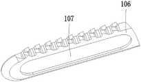
在术中切割的过程中会遇到另一问题,当对一截面较大,组织较厚的骨质进行离断时,超声手术刀刀头会不可避免地长时间埋入骨质内。现如今主流的超声手术刀皆为片状结构,在厚度方向分别具有两个大面积的端面106。在刀片埋入组织内部时,平面结构会对已切除平面进行长时间的接触,在超声的作用下,会产生大量的热,容易造成切割创面的二次升温而影响骨头愈合。且需要超声发生器输出更多的能量,作用在这个无效输出上,对硬件的输出功率也提出了更高的需求。为解决这一问题,如图10所示的本发明的第二实施例,在每个所述端面106上均开设有凹槽107。该实施例中,所示凹槽107呈跑道形,单侧凹槽的深度不大于总厚度的25%,中间留下的实质大于总厚度的50%,保留足够的机械强度。凹槽的总长度大于切割锯齿的总长度。当然,其他形状的凹槽107也是允许的。Another problem will be encountered in the process of intraoperative cutting. When a bone with a large cross-section and thick tissue is severed, the ultrasonic scalpel blade will inevitably be buried in the bone for a long time. The current mainstream ultrasonic scalpels are all sheet-like structures with two large-area end faces 106 in the thickness direction respectively. When the blade is embedded in the tissue, the plane structure will contact the excised plane for a long time. Under the action of ultrasound, a lot of heat will be generated, which will easily cause the secondary heating of the cutting wound and affect bone healing. In addition, the ultrasonic generator needs to output more energy, acting on this invalid output, which also puts forward a higher demand for the output power of the hardware. To solve this problem, in the second embodiment of the present invention shown in FIG. 10 , a
如图11和图12揭示的本发明的第三实施例,与优选实施例的区别在于,所述刀头113的一侧沿主体轴线延伸设置有锯齿排102,其对称的另一侧设置有切割刃108。这样,操作者可以有选择地选用锯齿排102或者切割刃108进行切割,扩大了本发明的使用场景。The third embodiment of the present invention disclosed in FIGS. 11 and 12 differs from the preferred embodiment in that one side of the
如图13揭示的本发明的第四实施例,与第三实施例相比,增加了端面106上的凹槽107。该效果与第二实施例类似,在此不再赘述。In the fourth embodiment of the present invention disclosed in FIG. 13 , compared with the third embodiment,
如图14、15所示的第五、第六实施例中,与图1、图10所示的优选实施例、第二实施例相比,所述刀头113的刀刃101为半圆形钝口刀刃。这样,当超声发生器产生的超声波传递至刀刃时,产生更强的驱离的效果,保护血管、神经等脆弱组织,且不易对其产生刮伤,可以对这些组织产生很好的保护效果。如图15所示的第六实施例中,增加了端面106上的凹槽107,该效果与第二实施例类似,在此不再赘述。当然,本领域的技术人员应该熟知,所述刀头113的刀刃101还可以是其他形式,例如锯齿刀刃等。In the fifth and sixth embodiments shown in FIGS. 14 and 15 , compared with the preferred embodiment and the second embodiment shown in FIGS. 1 and 10 , the
应当理解,虽然本说明书按照实施方式加以描述,但并非每个实施方式仅包含一个独立的技术方案,说明书的这种叙述方式仅仅是为清楚起见,本领域技术人员应当将说明书作为一个整体,各实施方式中的技术方案也可以经适当组合,形成本领域技术人员可以理解的其他实施方式。It should be understood that although this specification is described in terms of embodiments, not every embodiment only includes an independent technical solution, and this description in the specification is only for the sake of clarity, and those skilled in the art should take the specification as a whole, and each The technical solutions in the embodiments can also be appropriately combined to form other embodiments that can be understood by those skilled in the art.
上文所列出的一系列的详细说明仅仅是针对本发明的可行性实施方式的具体说明,它们并非用以限制本发明的保护范围,凡未脱离本发明技艺精神所作的等效实施方式或变更均应包含在本发明的保护范围之内。The series of detailed descriptions listed above are only specific descriptions for the feasible embodiments of the present invention, and they are not used to limit the protection scope of the present invention. Changes should all be included within the protection scope of the present invention.
Claims (20)
Priority Applications (2)
| Application Number | Priority Date | Filing Date | Title |
|---|---|---|---|
| CN202210102850.7ACN114431921A (en) | 2022-01-27 | 2022-01-27 | Ultrasonic scalpel and its blade |
| PCT/CN2022/124547WO2023142525A1 (en) | 2022-01-27 | 2022-10-11 | Ultrasonic scalpel and scalpel head thereof |
Applications Claiming Priority (1)
| Application Number | Priority Date | Filing Date | Title |
|---|---|---|---|
| CN202210102850.7ACN114431921A (en) | 2022-01-27 | 2022-01-27 | Ultrasonic scalpel and its blade |
Publications (1)
| Publication Number | Publication Date |
|---|---|
| CN114431921Atrue CN114431921A (en) | 2022-05-06 |
Family
ID=81368844
Family Applications (1)
| Application Number | Title | Priority Date | Filing Date |
|---|---|---|---|
| CN202210102850.7APendingCN114431921A (en) | 2022-01-27 | 2022-01-27 | Ultrasonic scalpel and its blade |
Country Status (2)
| Country | Link |
|---|---|
| CN (1) | CN114431921A (en) |
| WO (1) | WO2023142525A1 (en) |
Citations (6)
| Publication number | Priority date | Publication date | Assignee | Title |
|---|---|---|---|---|
| CN2915341Y (en)* | 2006-02-21 | 2007-06-27 | 曹孟君 | Saw bit, band knife and saw of reciprocating machine |
| CN202317265U (en)* | 2011-11-04 | 2012-07-11 | 本溪工具有限责任公司 | Double-metal band saw for cutting high-hardness or high-plasticity material |
| US20160374706A1 (en)* | 2008-06-12 | 2016-12-29 | Integra Lifesciences (Ireland) Ltd. | Shear stress ultrasonic cutting blade |
| CN208230984U (en)* | 2017-12-29 | 2018-12-14 | 杭州西姆森机械有限公司 | A kind of bi-metal bandsaw blades for cutting die steel |
| US20200178999A1 (en)* | 2017-05-31 | 2020-06-11 | Mectron S.P.A. | An ultrasonic cutting device for osteotomy |
| CN217285954U (en)* | 2022-01-27 | 2022-08-26 | 以诺康医疗科技(苏州)有限公司 | Ultrasonic scalpel and its blade |
Family Cites Families (7)
| Publication number | Priority date | Publication date | Assignee | Title |
|---|---|---|---|---|
| CN1241524C (en)* | 2004-03-22 | 2006-02-15 | 清华大学 | Supersonic skeleton cutting instrument |
| CN1745721A (en)* | 2005-07-15 | 2006-03-15 | 北京博达高科技有限公司 | Bone-operating ultrasonic knife with expanding function |
| CN204890115U (en)* | 2015-08-14 | 2015-12-23 | 北京宏仁凝瑞科技发展有限公司 | A scalpel for ultrasonic surgery scalpel system |
| CN107320151B (en)* | 2016-04-28 | 2020-12-01 | 北京水木天蓬医疗技术有限公司 | Ultrasonic osteotome head |
| US10660663B2 (en)* | 2016-05-25 | 2020-05-26 | Ethicon Llc | Ultrasonic surgical instrument blade with heat reduction feature |
| CN206047244U (en)* | 2016-08-29 | 2017-03-29 | 杭州西姆森机械有限公司 | A kind of interrupted cut strengthens the bands for band of tensile type |
| CN208322316U (en)* | 2017-08-17 | 2019-01-04 | 江苏爱利德科技有限公司 | Bimetallic multiform displacement saw blade |
- 2022
- 2022-01-27CNCN202210102850.7Apatent/CN114431921A/enactivePending
- 2022-10-11WOPCT/CN2022/124547patent/WO2023142525A1/ennot_activeCeased
Patent Citations (6)
| Publication number | Priority date | Publication date | Assignee | Title |
|---|---|---|---|---|
| CN2915341Y (en)* | 2006-02-21 | 2007-06-27 | 曹孟君 | Saw bit, band knife and saw of reciprocating machine |
| US20160374706A1 (en)* | 2008-06-12 | 2016-12-29 | Integra Lifesciences (Ireland) Ltd. | Shear stress ultrasonic cutting blade |
| CN202317265U (en)* | 2011-11-04 | 2012-07-11 | 本溪工具有限责任公司 | Double-metal band saw for cutting high-hardness or high-plasticity material |
| US20200178999A1 (en)* | 2017-05-31 | 2020-06-11 | Mectron S.P.A. | An ultrasonic cutting device for osteotomy |
| CN208230984U (en)* | 2017-12-29 | 2018-12-14 | 杭州西姆森机械有限公司 | A kind of bi-metal bandsaw blades for cutting die steel |
| CN217285954U (en)* | 2022-01-27 | 2022-08-26 | 以诺康医疗科技(苏州)有限公司 | Ultrasonic scalpel and its blade |
Also Published As
| Publication number | Publication date |
|---|---|
| WO2023142525A1 (en) | 2023-08-03 |
Similar Documents
| Publication | Publication Date | Title |
|---|---|---|
| CN107595368B (en) | Ultrasonic surgical tool bit, cutter bar and ultrasonic surgical knife | |
| TR201815810T1 (en) | Lathe for ultrasonic osteotome. | |
| WO2023142526A1 (en) | Ultrasonic scalpel bit | |
| CN206424121U (en) | A kind of ultrasonic osteotome bit | |
| WO2019052295A1 (en) | ULTRASOUND BONE CUTTING BLADE | |
| CN102429705B (en) | Minimally Invasive Scalpels for Surgery | |
| CN217285954U (en) | Ultrasonic scalpel and its blade | |
| CN110327100A (en) | A kind of ultrasonic surgical blade | |
| CN116983053B (en) | Ultrasonic scalpel head | |
| WO2023142527A1 (en) | Ultrasonic scalpel head | |
| CN217447921U (en) | Ultrasonic scalpel head | |
| CN206044757U (en) | A kind of non-elastic root canal file for waiting shaft section | |
| CN102697569B (en) | Ultrasonic bone knife head for tooth implantation | |
| CN114431921A (en) | Ultrasonic scalpel and its blade | |
| CN217447922U (en) | Ultrasonic knife head | |
| CN217447926U (en) | Ultrasonic knife with striking function and knife head | |
| CN210249992U (en) | Bone cutter for ultrasonic surgical system | |
| CN203369938U (en) | Ultrasonic bone knife machine working tip | |
| CN115500900A (en) | Cutting part, transition part and ultrasonic scalpel for ultrasonic scalpel | |
| CN211156054U (en) | A medical working tip, ultrasonic bone cutter machine and ultrasonic dental scaler | |
| RU2843786C2 (en) | Ultrasonic scalpel nozzle | |
| CN110575231B (en) | Cutter bar structure of ultrasonic knife and ultrasonic knife | |
| CN222640554U (en) | Ultrasonic hemostatic cutter head structure | |
| CN216908043U (en) | Blade structure and saw blade of oscillating saw blade | |
| CN221671867U (en) | A hollow working tip with saw teeth |
Legal Events
| Date | Code | Title | Description |
|---|---|---|---|
| PB01 | Publication | ||
| PB01 | Publication | ||
| SE01 | Entry into force of request for substantive examination | ||
| SE01 | Entry into force of request for substantive examination | ||
| CB02 | Change of applicant information | Country or region after:China Address after:215000 Jiangsu Province, Suzhou City, Industrial Park, Xinghu Street 218, Room B2-409 Applicant after:Enkang Medical Technology (Suzhou) Co., Ltd. Address before:215000 Jiangsu Province, Suzhou City, Industrial Park, Xinghu Street 218, Room B2-409 Applicant before:INNOLCON MEDICAL TECHNOLOGY (SUZHOU) Co.,Ltd. Country or region before:China | |
| CB02 | Change of applicant information |