CN114430881B - Motor driving method and motor driving device - Google Patents
Motor driving method and motor driving deviceDownload PDFInfo
- Publication number
- CN114430881B CN114430881BCN202080066279.7ACN202080066279ACN114430881BCN 114430881 BCN114430881 BCN 114430881BCN 202080066279 ACN202080066279 ACN 202080066279ACN 114430881 BCN114430881 BCN 114430881B
- Authority
- CN
- China
- Prior art keywords
- motor
- speed
- speed range
- range
- driving method
- Prior art date
- Legal status (The legal status is an assumption and is not a legal conclusion. Google has not performed a legal analysis and makes no representation as to the accuracy of the status listed.)
- Active
Links
Images


Classifications
- H—ELECTRICITY
- H02—GENERATION; CONVERSION OR DISTRIBUTION OF ELECTRIC POWER
- H02P—CONTROL OR REGULATION OF ELECTRIC MOTORS, ELECTRIC GENERATORS OR DYNAMO-ELECTRIC CONVERTERS; CONTROLLING TRANSFORMERS, REACTORS OR CHOKE COILS
- H02P6/00—Arrangements for controlling synchronous motors or other dynamo-electric motors using electronic commutation dependent on the rotor position; Electronic commutators therefor
- H02P6/14—Electronic commutators
- H02P6/16—Circuit arrangements for detecting position
- H02P6/18—Circuit arrangements for detecting position without separate position detecting elements
- H—ELECTRICITY
- H02—GENERATION; CONVERSION OR DISTRIBUTION OF ELECTRIC POWER
- H02P—CONTROL OR REGULATION OF ELECTRIC MOTORS, ELECTRIC GENERATORS OR DYNAMO-ELECTRIC CONVERTERS; CONTROLLING TRANSFORMERS, REACTORS OR CHOKE COILS
- H02P21/00—Arrangements or methods for the control of electric machines by vector control, e.g. by control of field orientation
- H02P21/04—Arrangements or methods for the control of electric machines by vector control, e.g. by control of field orientation specially adapted for very low speeds
- H—ELECTRICITY
- H02—GENERATION; CONVERSION OR DISTRIBUTION OF ELECTRIC POWER
- H02P—CONTROL OR REGULATION OF ELECTRIC MOTORS, ELECTRIC GENERATORS OR DYNAMO-ELECTRIC CONVERTERS; CONTROLLING TRANSFORMERS, REACTORS OR CHOKE COILS
- H02P21/00—Arrangements or methods for the control of electric machines by vector control, e.g. by control of field orientation
- H02P21/05—Arrangements or methods for the control of electric machines by vector control, e.g. by control of field orientation specially adapted for damping motor oscillations, e.g. for reducing hunting
- H—ELECTRICITY
- H02—GENERATION; CONVERSION OR DISTRIBUTION OF ELECTRIC POWER
- H02P—CONTROL OR REGULATION OF ELECTRIC MOTORS, ELECTRIC GENERATORS OR DYNAMO-ELECTRIC CONVERTERS; CONTROLLING TRANSFORMERS, REACTORS OR CHOKE COILS
- H02P21/00—Arrangements or methods for the control of electric machines by vector control, e.g. by control of field orientation
- H02P21/22—Current control, e.g. using a current control loop
- H—ELECTRICITY
- H02—GENERATION; CONVERSION OR DISTRIBUTION OF ELECTRIC POWER
- H02P—CONTROL OR REGULATION OF ELECTRIC MOTORS, ELECTRIC GENERATORS OR DYNAMO-ELECTRIC CONVERTERS; CONTROLLING TRANSFORMERS, REACTORS OR CHOKE COILS
- H02P21/00—Arrangements or methods for the control of electric machines by vector control, e.g. by control of field orientation
- H02P21/24—Vector control not involving the use of rotor position or rotor speed sensors
- H—ELECTRICITY
- H02—GENERATION; CONVERSION OR DISTRIBUTION OF ELECTRIC POWER
- H02P—CONTROL OR REGULATION OF ELECTRIC MOTORS, ELECTRIC GENERATORS OR DYNAMO-ELECTRIC CONVERTERS; CONTROLLING TRANSFORMERS, REACTORS OR CHOKE COILS
- H02P23/00—Arrangements or methods for the control of AC motors characterised by a control method other than vector control
- H02P23/03—Arrangements or methods for the control of AC motors characterised by a control method other than vector control specially adapted for very low speeds
- H—ELECTRICITY
- H02—GENERATION; CONVERSION OR DISTRIBUTION OF ELECTRIC POWER
- H02P—CONTROL OR REGULATION OF ELECTRIC MOTORS, ELECTRIC GENERATORS OR DYNAMO-ELECTRIC CONVERTERS; CONTROLLING TRANSFORMERS, REACTORS OR CHOKE COILS
- H02P23/00—Arrangements or methods for the control of AC motors characterised by a control method other than vector control
- H02P23/04—Arrangements or methods for the control of AC motors characterised by a control method other than vector control specially adapted for damping motor oscillations, e.g. for reducing hunting
- H—ELECTRICITY
- H02—GENERATION; CONVERSION OR DISTRIBUTION OF ELECTRIC POWER
- H02P—CONTROL OR REGULATION OF ELECTRIC MOTORS, ELECTRIC GENERATORS OR DYNAMO-ELECTRIC CONVERTERS; CONTROLLING TRANSFORMERS, REACTORS OR CHOKE COILS
- H02P23/00—Arrangements or methods for the control of AC motors characterised by a control method other than vector control
- H02P23/14—Estimation or adaptation of motor parameters, e.g. rotor time constant, flux, speed, current or voltage
- H—ELECTRICITY
- H02—GENERATION; CONVERSION OR DISTRIBUTION OF ELECTRIC POWER
- H02P—CONTROL OR REGULATION OF ELECTRIC MOTORS, ELECTRIC GENERATORS OR DYNAMO-ELECTRIC CONVERTERS; CONTROLLING TRANSFORMERS, REACTORS OR CHOKE COILS
- H02P23/00—Arrangements or methods for the control of AC motors characterised by a control method other than vector control
- H02P23/20—Controlling the acceleration or deceleration
- H—ELECTRICITY
- H02—GENERATION; CONVERSION OR DISTRIBUTION OF ELECTRIC POWER
- H02P—CONTROL OR REGULATION OF ELECTRIC MOTORS, ELECTRIC GENERATORS OR DYNAMO-ELECTRIC CONVERTERS; CONTROLLING TRANSFORMERS, REACTORS OR CHOKE COILS
- H02P29/00—Arrangements for regulating or controlling electric motors, appropriate for both AC and DC motors
- H02P29/02—Providing protection against overload without automatic interruption of supply
- H02P29/032—Preventing damage to the motor, e.g. setting individual current limits for different drive conditions
- H—ELECTRICITY
- H02—GENERATION; CONVERSION OR DISTRIBUTION OF ELECTRIC POWER
- H02P—CONTROL OR REGULATION OF ELECTRIC MOTORS, ELECTRIC GENERATORS OR DYNAMO-ELECTRIC CONVERTERS; CONTROLLING TRANSFORMERS, REACTORS OR CHOKE COILS
- H02P2207/00—Indexing scheme relating to controlling arrangements characterised by the type of motor
- H02P2207/05—Synchronous machines, e.g. with permanent magnets or DC excitation
Landscapes
- Engineering & Computer Science (AREA)
- Power Engineering (AREA)
- Control Of Ac Motors In General (AREA)
- Control Of Electric Motors In General (AREA)
- Control Of Motors That Do Not Use Commutators (AREA)
Abstract
Description
Translated fromChinese技术领域technical field
本公开涉及马达(motor)驱动方法和马达驱动装置。The present disclosure relates to a motor driving method and a motor driving device.
背景技术Background technique
以往,作为马达的控制方式,已知一种不使用检测马达的旋转位置的位置传感器来控制马达的无位置传感器(position sensorless)控制(例如,参见专利文件1)。Conventionally, as a motor control method, there is known a position sensorless control in which the motor is controlled without using a position sensor for detecting the rotational position of the motor (for example, see Patent Document 1).
[引证文件][citing document]
[专利文件][Patent Document]
[专利文件1](日本)特开2011-91976号公报[Patent Document 1] (Japanese) Unexamined Patent Application Publication No. 2011-91976
发明内容Contents of the invention
[要解决的技术问题][Technical problem to be solved]
然而,由于马达的控制方式的不同,当使马达在低速区域内运转(operation)时,存在难以使马达稳定运转的情况。However, depending on the control method of the motor, when the motor is operated in a low-speed range, it may be difficult to operate the motor stably.
本公开提出一种能够使马达稳定运转的马达驱动方法和马达驱动装置。The present disclosure proposes a motor driving method and a motor driving device capable of stably operating the motor.
[技术方案][Technical solutions]
本公开的一方面的马达驱动方法是一种由马达驱动装置对马达进行驱动的方法,该马达驱动装置具备对供给至同步机(synchronous machine)即马达的供给电力进行调整的逆变器(invertor)和对所述逆变器进行控制的控制器(controlor),其中,当将能够使所述马达以大致恒定的速度进行运转的速度区域作为第1速度区域,并将低于所述第1速度区域且包含零速度的速度区域作为第2速度区域时,使所述马达的速度在失步之前从所述第2速度区域过渡到所述第1速度区域内。A motor driving method according to one aspect of the present disclosure is a method of driving a motor by a motor driving device including an inverter that adjusts power supplied to a motor that is a synchronous machine. ) and a controller (controller) for controlling the inverter, wherein the speed range in which the motor can be operated at a substantially constant speed is taken as the first speed range, and the speed lower than the first When the speed range including zero speed is used as the second speed range, the speed of the motor is transitioned from the second speed range to the first speed range before a step is lost.
根据上述一方面的马达驱动方法,即使在低于所述第1速度区域的所述第2速度区域内使所述马达运转,所述马达的速度也可在失步之前从所述第2速度区域过渡到所述第1速度区域内。据此,由于可确保所述马达的旋转的稳定性,所以可使所述马达稳定运转。According to the motor driving method of the above aspect, even if the motor is operated in the second speed range lower than the first speed range, the speed of the motor can be changed from the second speed to region transitions into the first speed region. According to this, since the stability of the rotation of the motor can be ensured, the motor can be operated stably.
上述马达驱动方法中,所述马达是对泵进行驱动的马达,对所述泵的排出压力进行检测,所述第1速度区域至少包含所述马达进行正向旋转的正向旋转区域,如果当所述马达的速度位于所述正向旋转区域内时从所述泵的排出压力减去目标压力后的偏差超过第1阈值,则可使所述马达的速度过渡到所述第2速度区域内。In the motor driving method described above, the motor is a motor that drives a pump, and the discharge pressure of the pump is detected, and the first speed region includes at least a forward rotation region where the motor performs forward rotation. When the speed of the motor is in the forward rotation range, the deviation obtained by subtracting the target pressure from the discharge pressure of the pump exceeds a first threshold value, and the speed of the motor can be transitioned to the second speed range. .
据此,即使所述马达的速度随所述偏差超过所述第1阈值而过渡到所述第2速度区域内,所述马达的速度也可在失步之前从所述第2速度区域过渡到所述第1速度区域内。因此,可确保所述马达的旋转的稳定性,进而可使所述马达稳定运转。Accordingly, even if the speed of the motor transitions into the second speed range as the deviation exceeds the first threshold, the speed of the motor can transition from the second speed range to within the first speed zone. Therefore, the stability of the rotation of the motor can be ensured, and thus the motor can be operated stably.
上述马达驱动方法中,当将所述第1阈值以下的阈值作为第2阈值时,如果所述马达的速度过渡到所述第2速度区域内后从所述泵的排出压力减去目标压力后的偏差低于所述第2阈值,则可使所述马达的速度在失步之前过渡到所述正向旋转区域内。In the motor driving method described above, when a threshold value equal to or less than the first threshold value is used as the second threshold value, if the speed of the motor transitions to within the second speed range, the target pressure is subtracted from the discharge pressure of the pump. If the deviation is lower than the second threshold value, the speed of the motor can be transitioned into the forward rotation region before stepping out.
据此,一旦所述马达的速度过渡到所述第2速度区域内后所述偏差变为低于所述第2阈值,则所述马达的速度可在失步之前过渡到所述正向旋转区域内。因此,可确保所述马达的旋转的稳定性,进而可使所述马达稳定运转。Accordingly, once the deviation becomes lower than the second threshold value after the speed of the motor transitions into the second speed region, the speed of the motor can transition to the forward rotation before stepping out within the area. Therefore, the stability of the rotation of the motor can be ensured, and thus the motor can be operated stably.
上述马达驱动方法中,可禁止所述马达在所述第2速度区域内以大致恒定的速度进行运转。In the motor driving method described above, the motor may be prohibited from operating at a substantially constant speed in the second speed range.
据此,所述马达的速度可在失步之前从所述第2速度区域迅速过渡到所述第1速度区域内。因此,可确保所述马达的旋转的稳定性,进而可使所述马达稳定运转。According to this, the speed of the motor can quickly transition from the second speed range to the first speed range before a step is lost. Therefore, the stability of the rotation of the motor can be ensured, and thus the motor can be operated stably.
上述马达驱动方法中,在从所述马达的速度过渡到所述第2速度区域内开始至所述马达失步为止的期间内,可使所述马达的速度从所述第2速度区域过渡到所述第1速度区域内。In the motor driving method described above, the speed of the motor may be made to transition from the second speed range to the second speed range during the period from when the speed of the motor transitions into the second speed range to when the motor is out of step. within the first speed zone.
据此,所述马达的速度可在过渡到所述第2速度区域内开始至所述马达失步之前过渡到所述第1速度区域内。因此,可确保所述马达的旋转的稳定性,进而可使所述马达稳定运转。Accordingly, the speed of the motor can transition to the first speed range before the motor is out of step from the time of transition to the second speed range. Therefore, the stability of the rotation of the motor can be ensured, and thus the motor can be operated stably.
上述马达驱动方法中,所述期间可为1秒。In the motor driving method described above, the period may be 1 second.
据此,所述马达的速度可在从过渡到所述第2速度区域内开始至所述马达失步之前的1秒的期间内过渡到所述第1速度区域内。因此,可确保所述马达的旋转的稳定性,进而可使所述马达稳定运转。Accordingly, the speed of the motor can transition to the first speed range within a period of one second from the transition to the second speed range until the motor is out of step. Therefore, the stability of the rotation of the motor can be ensured, and thus the motor can be operated stably.
上述马达驱动方法中,生成使所述泵的排出压力接近目标压力的原始指令速度,并可在所述原始指令速度位于所述第2速度区域内的期间使所述原始指令速度过渡到所述第1速度区域内。In the motor driving method described above, an original command speed is generated to bring the discharge pressure of the pump close to the target pressure, and the original command speed may be transitioned to the second speed range while the original command speed is within the second speed range. In the 1st speed zone.
据此,即使生成了所述原始指令速度,在所述原始指令速度位于所述第2速度区域内的期间,所述原始指令速度也可过渡到所述第1速度区域内,所以可抑制所述马达的速度停留在所述第2速度区域内。因此,由于所述马达的速度可在失步之前从所述第2速度区域迅速过渡到所述第1速度区域内,所以可确保所述马达的旋转的稳定性,进而可使所述马达稳定运转。According to this, even if the original command speed is generated, the original command speed can transition to the first speed range while the original command speed is in the second speed range, so that the original command speed can be suppressed. The speed of the motor stays within the second speed range. Therefore, since the speed of the motor can be quickly transitioned from the second speed range to the first speed range before the step is lost, the stability of the rotation of the motor can be ensured, and thus the motor can be stabilized. run.
上述马达驱动方法中,生成使所述泵的排出压力接近目标压力的原始指令速度,所述第1速度区域包含所述正向旋转区域和所述马达进行逆向旋转的逆向旋转区域,如果当所述马达的速度位于所述正向旋转区域内时从所述泵的排出压力减去目标压力后的偏差超过所述第1阈值,则可使所述原始指令速度过渡到所述逆向旋转区域内。In the motor driving method described above, an original command speed is generated to bring the discharge pressure of the pump close to the target pressure, and the first speed range includes the forward rotation range and the reverse rotation range in which the motor performs reverse rotation. When the speed of the motor is within the forward rotation range, the deviation obtained by subtracting the target pressure from the discharge pressure of the pump exceeds the first threshold value, and the original command speed can be transitioned to the reverse rotation range. .
据此,一旦当所述马达的速度位于所述正向旋转区域内时所述偏差超过所述第1阈值,则由于所述原始指令速度可过渡到所述逆向旋转区域内,所以可使所述马达逆向旋转,以使所述偏差迅速变小。According to this, once the deviation exceeds the first threshold when the speed of the motor is within the forward rotation range, the original command speed can transition into the reverse rotation range, so that the The motor rotates in reverse so that the deviation becomes smaller rapidly.
上述马达驱动方法中,生成使所述泵的排出压力接近目标压力的原始指令速度,所述第1速度区域包含所述正向旋转区域和所述马达进行逆向旋转的逆向旋转区域,如果当所述马达的速度位于所述第2速度区域或所述逆向旋转区域内时从所述泵的排出压力减去目标压力后的偏差低于所述第2阈值,则可使所述原始指令速度过渡到所述正向旋转区域内。In the motor driving method described above, an original command speed is generated to bring the discharge pressure of the pump close to the target pressure, and the first speed range includes the forward rotation range and the reverse rotation range in which the motor performs reverse rotation. When the speed of the motor is in the second speed range or the reverse rotation range, the deviation obtained by subtracting the target pressure from the discharge pressure of the pump is lower than the second threshold value, and the original command speed can be transitioned. into the forward rotation region.
据此,一旦当所述马达的速度位于所述第2速度区域或所述逆向旋转区域内时所述偏差变为低于所述第2阈值,则由于所述原始指令速度可过渡到所述正向旋转区域内,所以可使所述马达的速度迅速上升至所述正向旋转区域内。Accordingly, once the deviation becomes lower than the second threshold value when the speed of the motor is within the second speed range or the reverse rotation range, since the original command speed can transition to the In the forward rotation area, the speed of the motor can be rapidly increased to the forward rotation area.
上述马达驱动方法中,如果将所述马达驱动装置驱动所述马达时所述马达能够输出的最大扭矩(torque)作为最大输出扭矩,则在所述马达的速度位于所述第2速度区域内时可使所述马达的输出扭矩低于所述最大输出扭矩。In the above motor driving method, if the maximum torque that the motor can output when the motor driving device drives the motor is taken as the maximum output torque, when the speed of the motor is within the second speed range The output torque of the motor may be lower than the maximum output torque.
所述最大输出扭矩由所述马达的设备常数、所述控制器的控制常数、所述马达的电流容量等确定。一般而言,由于存在经时变化、温度特性、个体差异等因素(例如,无位置传感器控制中,这些因素会导致产生位置推定(估计)误差),所以在输出了所述最大输出扭矩的状态下,难以使所述马达以大致一定(恒定)的速度稳定运转。此外,如果所述马达的输出扭矩下降,则所述马达的旋转的稳定性增加。根据上述马达驱动方法,当所述马达的速度位于所述第2速度区域内时,所述马达的输出扭矩不会停留(粘滞)于所述最大输出扭矩,所述马达的输出扭矩低于所述最大输出扭矩。因此,由于提高了所述马达的旋转的稳定性,所以可使所述马达在低速区域内稳定运转。The maximum output torque is determined by a device constant of the motor, a control constant of the controller, a current capacity of the motor, and the like. In general, due to factors such as changes over time, temperature characteristics, and individual differences (for example, in position sensorless control, these factors cause position estimation (estimation) errors), so in the state where the maximum output torque is output In this case, it is difficult to stably operate the motor at a substantially constant (constant) speed. In addition, if the output torque of the motor decreases, the stability of the rotation of the motor increases. According to the motor driving method described above, when the speed of the motor is within the second speed range, the output torque of the motor does not stay (stick) at the maximum output torque, and the output torque of the motor is lower than The maximum output torque. Therefore, since the rotation stability of the motor is improved, the motor can be stably operated in a low-speed region.
上述马达驱动方法中,所述马达的电流或电压的谐波分量(harmonic component)中的不依赖于所述马达的旋转的频率在所述第1速度区域和所述第2速度区域内可大致相同(大致一致)。In the motor driving method described above, the frequency of a harmonic component (harmonic component) of the current or voltage of the motor that does not depend on the rotation of the motor may be substantially same (roughly the same).
据此,可使所述马达更稳定地进行运转。Accordingly, the motor can be operated more stably.
上述马达驱动方法中,当所述马达的速度位于所述第2速度区域内时,所述马达的扭矩常数可为受控制的状态。In the motor driving method described above, when the speed of the motor is within the second speed range, the torque constant of the motor may be controlled.
据此,可使所述马达更稳定地进行运转。Accordingly, the motor can be operated more stably.
上述马达驱动方法中,可不使用检测所述马达的旋转位置的位置传感器来控制所述马达。In the motor driving method described above, the motor may be controlled without using a position sensor that detects the rotational position of the motor.
据此,即使在不使用位置传感器控制所述马达的控制方式中,也可使所述马达稳定运转。According to this, even in a control method in which the motor is controlled without using a position sensor, the motor can be operated stably.
本公开的一方面的马达驱动装置具备对供给至同步机即马达的供给电力进行调整的逆变器和对所述逆变器进行控制的控制器,其中,当将能够使所述马达以大致恒定的速度进行运转的速度区域作为第1速度区域,并将低于所述第1速度区域且包含零速度的速度区域作为第2速度区域时,所述控制器使所述马达的速度在失步之前从所述第2速度区域过渡到所述第1速度区域内。A motor drive device according to one aspect of the present disclosure includes an inverter that adjusts power supplied to a motor, which is a synchronous machine, and a controller that controls the inverter. When the speed range for running at a constant speed is set as the first speed range, and the speed range lower than the first speed range and including zero speed is set as the second speed range, the controller makes the speed of the motor transition from the second speed range to the first speed range before the step.
根据上述一方面的马达驱动装置,即使在低于所述第1速度区域的所述第2速度区域内使所述马达运转,所述马达的速度也可在失步之前从所述第2速度区域过渡到所述第1速度区域内。据此,由于可确保所述马达的旋转的稳定性,所以可使所述马达稳定运转。According to the motor drive device according to the above aspect, even if the motor is operated in the second speed range lower than the first speed range, the speed of the motor can be changed from the second speed to region transitions into the first speed region. According to this, since the stability of the rotation of the motor can be ensured, the motor can be operated stably.
上述马达驱动装置中,可不使用检测所述马达的旋转位置的位置传感器来控制所述马达。In the motor drive device described above, the motor may be controlled without using a position sensor that detects the rotational position of the motor.
据此,即使在不使用位置传感器控制所述马达的控制方式中,也可使所述马达稳定运转。According to this, even in a control method in which the motor is controlled without using a position sensor, the motor can be operated stably.
附图说明Description of drawings
[图1]具备第1实施方式的马达驱动装置的流体压力单元的构成例的示意图。[ Fig. 1] Fig. 1 is a schematic diagram of a configuration example of a fluid pressure unit provided with a motor drive device according to a first embodiment.
[图2]压力-流量图的一例的示意图。[ Fig. 2 ] A schematic diagram of an example of a pressure-flow rate diagram.
[图3]表示马达的转数和输出扭矩之间的关系的马达特性的例示图。[ Fig. 3 ] An illustration diagram of motor characteristics showing the relationship between the number of revolutions of the motor and the output torque.
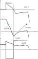
[图4]不使用本公开的控制的一个比较方式的马达驱动装置的控制波形的一例的示意图。[ Fig. 4] Fig. 4 is a schematic diagram of an example of a control waveform of a motor drive device of a comparative mode not using the control of the present disclosure.
[图5]使用本公开的控制的第1实施方式的马达驱动装置的控制波形的一例的示意图。[ Fig. 5] Fig. 5 is a schematic diagram of an example of a control waveform of the motor drive device according to the first embodiment using the control of the present disclosure.
[图6]具备第2实施方式的马达驱动装置的流体压力单元的构成例的示意图。[ Fig. 6] Fig. 6 is a schematic diagram of a configuration example of a fluid pressure unit provided with a motor drive device according to a second embodiment.
[图7]使用本公开的控制的第2实施方式的马达驱动装置的控制波形的一例的示意图。[ Fig. 7] Fig. 7 is a schematic diagram of an example of a control waveform of a motor drive device according to a second embodiment using the control of the present disclosure.
具体实施方式Detailed ways
下面对实施方式进行说明。Embodiments are described below.
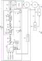
图1是具备第1实施方式的马达驱动装置的流体压力单元的构成例的示意图。图1所示的液压单元200通过由逆变器17控制的马达(电动机)10驱动泵(pump)11,将罐(tank)12内的流体供给至气缸(cylinder)等的致动器(actuator)13。在流体为油的情况下,流体压力单元也被称为油压单元。流体不限于油等的液体,也可为气体。FIG. 1 is a schematic diagram of a configuration example of a fluid pressure unit provided with a motor drive device according to a first embodiment. The
需要说明的是,本公开的马达驱动装置和马达驱动方法不限于对安装于流体压力单元的马达进行驱动的情况,也可应用于对安装于流体压力单元以外的设备(例如,藉由马达对气体进行压缩的压缩机等)的马达进行驱动的情况。It should be noted that the motor driving device and motor driving method of the present disclosure are not limited to the situation of driving the motor installed in the fluid pressure unit, and can also be applied to equipment installed in other than the fluid pressure unit (for example, by the motor to When a motor that compresses gas, such as a compressor, etc.) is driven.
图1所示的流体压力单元200具备泵11、罐12、致动器13、马达10及马达驱动装置100。The
泵11经由吸入通道14从罐12吸出流体并对其进行压缩,然后经由排出通道15将压缩后的流体排出至致动器13。马达10被马达驱动装置100进行基于逆变器的控制以驱动泵11。The
马达驱动装置100不使用检测马达10的转子的位置(马达10的旋转位置)的位置传感器来驱动马达10。马达10为无位置传感器的同步机。马达驱动装置100具有压力传感器16、逆变器17及控制器20。由于无位置传感器马达驱动技术是已知的,所以在此不再赘述。The
压力传感器16检测从泵11排出的流体压力(排出压力),并将其所检测的排出压力(下面也称压力Pd)提供给控制器20。压力传感器16是对藉由马达的驱动而工作的设备(该例中为泵11)所接受的负荷进行检测的负荷检测部的一例。排出压力是该设备所接受的负荷的一例。The
马达驱动装置100还可具备扭矩传感器,该扭矩传感器检测马达10所接受的负荷扭矩,并将其所检测的负荷扭矩提供给控制器20。扭矩传感器是对马达所接受的负荷进行检测的负荷检测部的一例。The
逆变器17是对供给至马达10的供给电力进行调整的电路,例如,具有三相桥式电路。The inverter 17 is a circuit that adjusts the electric power supplied to the
控制器20输出对逆变器17进行控制的控制信号。控制器20以使泵11的排出压力变为目标压力或使马达的旋转速度变为响应于目标流量的速度的方式使逆变器17工作,由此对马达10进行控制。The
控制器20根据由压力传感器16检测的压力Pd、基于指令速度ω*而算出的流量Qd、及由目标压力-目标流量-马力限制而构成的图(也称PQ图)21对驱动马达10的逆变器17的动作进行控制。控制器20算出的流量Qd表示从泵11排出至排出通道15的流体的流量Q的估计值。The
控制器20通过由延迟元件28使指令速度ω*延迟来计算单位时间(例如,控制周期)之前的旧速度ω^。延迟元件28是使指令速度ω*延迟单位时间的延迟器。控制器20通过由乘法器31进行旧速度ω^[1/s]和泵11的容积q[m3]的乘法运算来计算流量Qd[m3/s]。泵11的容积q不变,故为固定值。控制器20根据从外部提供的目标压力Pr和由乘法器31算出的流量Qd从PQ图21导出目标马力Rr。另一方面,控制器20通过乘法器23进行由压力传感器16检测的压力Pd和由乘法器31算出的流量Qd的乘法运算,由此导出检测马力Rd(=Pd×Qd)。控制器20通过减法器22导出目标马力Rr和检测马力Rd的误差Re(=Rr-Rd)。控制器20具有PID控制部24,该PID控制部24藉由PID控制导出使误差Re接近零的原始指令速度ω**(PID中,P表示比例,I表示积分,D表示微分)。原始指令速度ω**也可藉由PI控制而被导出。原始指令速度ω**是使泵11的排出压力接近目标压力Pr的原始指令速度的一例。The
控制器20具有速度指令校正部30。速度指令校正部30通过由减法器34从原始指令速度ω**减去旧速度ω^来计算速度差Δ(=ω**-ω^),并通过由微分器25对速度差Δ进行微分来计算加速度Δω^。速度指令校正部30导出被限制器26限制在基于实际负荷状态(例如,转数(≈流量Q)和压力P)而设定的上限值以下的加速度Δω^(将从限制器26输出的加速度Δω^称为“加速度Δω*”)。加速度Δω^和Δω*表示每单位时间(例如,控制周期)的速度变化量。速度指令校正部30通过由加算器27将旧速度ω^加上每单位时间的速度变化量即加速度Δω*来计算马达10的指令速度ω*。控制器20具有电压设定部29,该电压设定部29根据指令速度ω*来设定使驱动马达10的逆变器17进行工作的指令电压Vr。The
控制器20所具备的PID控制部24等的各部分的功能藉由可读取地存储于存储器的程序使处理器(例如,CPU(Central Processing Unit))进行操作而实现。The functions of each part such as the
图2是压力-流量图的一例的示意图。PQ图21由与最大设定流量Q0对应的最大流量直线、由与最大马力限制L0对应的曲线构成的最大马力曲线、及与最高设定压力P0对应的最高压力直线构成。预定的压力P1为高于零且低于最高设定压力P0的压力。预定的流量Q1为多于零且少于最大设定流量Q0的流量。流量Q相当于马达10的旋转速度ω(转数)和泵11的容积q之积,故与旋转速度ω等价。FIG. 2 is a schematic diagram of an example of a pressure-flow rate diagram. The PQ diagram 21 is composed of a maximum flow rate straight line corresponding to the maximum set flow rate Q0, a maximum horsepower curve formed by a curve corresponding to the maximum horsepower limit L0, and a maximum pressure line corresponding to the maximum set pressure P0. The predetermined pressure P1 is a pressure higher than zero and lower than the maximum set pressure P0. The predetermined flow rate Q1 is more than zero and less than the maximum set flow rate Q0. The flow rate Q is equivalent to the product of the rotation speed ω (number of revolutions) of the
控制器20以使由压力传感器16检测的压力Pd和基于指令速度ω*算出的流量Qd位于PQ图21内的由设定压力Pn-设定流量Qn-设定马力曲线Ln构成的线上的方式,使驱动马达10的逆变器17进行工作。尤其是在流量Qd少于预定的流量Q1、且压力Pd大于预定的压力P1的工作区域(图2中的斜线区域)内使马达10进行加减速工作的情况下,控制器20通过降低马达10的输出扭矩,可实现马达10的运转的稳定化。The
图2所示的工作点p1、p2、p3中,p1为流量仅比预定的流量Q1大一点的工作点,p2为压力与p1相同但流量小于预定的流量Q1的工作点,p3为流量与p2相同但压力大于p2的工作点。图2所示的工作点p1、p2、p3在表示马达的转数N和输出扭矩T之间的关系的马达特性上与图3所示的工作点对应。图3所示的马达特性中,最大输出扭矩Tm表示马达驱动装置100驱动马达10时可从马达10输出的最大扭矩。输出扭矩Ts表示为了在低速时·高负荷时稳定地进行运转而从最大输出扭矩Tm被限制了的扭矩。从输出扭矩Ts减去马达10所接受的负荷扭矩Tb后的扭矩相当于马达10的加减速可使用的加速扭矩Ta。Among the operating points p1, p2, and p3 shown in Fig. 2, p1 is the operating point whose flow rate is only slightly larger than the predetermined flow rate Q1, p2 is the operating point whose pressure is the same as p1 but the flow rate is smaller than the predetermined flow rate Q1, and p3 is the flow rate and the predetermined flow rate Q1. The operating point where p2 is the same but the pressure is greater than p2. The operating points p1 , p2 , and p3 shown in FIG. 2 correspond to the operating points shown in FIG. 3 in terms of motor characteristics representing the relationship between the number of revolutions N of the motor and the output torque T. In the motor characteristics shown in FIG. 3 , the maximum output torque Tm represents the maximum torque that can be output from the
工作点p1处,由于流量不少于预定的流量Q1,所以对输出扭矩Ts不进行从最大输出扭矩Tm开始的限制。从工作点p1转移(过渡)到工作点p2后,流量变为小于预定的流量Q1,基于低于预定的流量Q1的大小来增大扭矩限制量Tc,输出扭矩Ts变为从最大输出扭矩Tm减去扭矩限制量Tc后的扭矩。由于工作点p1和工作点p2之间压力没有发生变化,所以负荷扭矩Tb的大小没有差异,加速扭矩Ta减少(下降)扭矩限制量Tc。此时,由于至少相当于该扭矩限制量Tc的电流量可流入马达10,所以也可增加相当于该电流量的无效电流,进而可提高旋转控制的稳定性。从工作点p2转移至工作点p3后,压力P的增加(参见图2)导致负荷扭矩Tb也增加(参见图3),为此,相当于该增加量的加速扭矩Ta不能再被使用。此时,由于扭矩限制量Tc随负荷变大而变大,所以能够用于加速扭矩Ta的量变得更少(参见图3)。这样,随马达10的旋转速度变低,或着,随马达10或泵11所接受的负荷(该例中为负荷扭矩Tb或压力P)变重,能够用于加速扭矩Ta的量变少,因此,马达10的输出扭矩下降。At the operating point p1, since the flow rate is not less than the predetermined flow rate Q1, the output torque Ts is not restricted from the maximum output torque Tm. After shifting (transitioning) from the operating point p1 to the operating point p2, the flow rate becomes smaller than the predetermined flow rate Q1, and the torque limit amount Tc is increased based on the magnitude of the flow rate lower than the predetermined flow rate Q1, and the output torque Ts changes from the maximum output torque Tm The torque obtained by subtracting the torque limit amount Tc. Since there is no change in pressure between the operating point p1 and the operating point p2, there is no difference in the magnitude of the load torque Tb, and the acceleration torque Ta decreases (decreases) by the torque limit amount Tc. At this time, since at least an amount of current corresponding to the torque limit amount Tc can flow into the
这里,如果将马达10的旋转速度ω(转数)设为N[1/s],将马达10的负荷扭矩设为Tb[Nm],将泵11的排出压力设为P[N/m2],将从泵11排出的流量设为Q[m3/s],将泵11的容积设为q[m3],则泵11的压力P和马达10所接受的负荷扭矩Tb之间的关系如下(公式1)。Here, if the rotation speed ω (number of revolutions) of the
2π×N×Tb=P×Q=P×N×q…公式12π×N×Tb=P×Q=P×N×q…
为此,通过对上述式1进行变形,可获得下述公式2。For this reason, the following
Tb=P×q/(2π)…公式2Tb=P×q/(2π)…
某时点的转数N时的输出扭矩Ts为,从基于图3所示的马达特性而确定的最大输出扭矩Tm减去扭矩限制量Tc后的值,某时点的转数N时的可用于加减速的加速扭矩Ta可根据下述公式3导出。The output torque Ts at the number of revolutions N at a certain point in time is the value obtained by subtracting the torque limit amount Tc from the maximum output torque Tm determined based on the motor characteristics shown in FIG. 3 . Acceleration torque Ta for acceleration and deceleration can be derived according to the following
Ta=Ts-Tb…式3Ta=Ts-Tb...
因此,速度指令校正部30(参见图1)藉由根据公式2和公式3而算出加速扭矩Ta,能够计算可用于加减速的扭矩的最大值。速度指令校正部30通过限制器26按照根据基于公式2和公式3而算出的加速扭矩Ta而设定的上限值对加速度Δω^进行限制。据此,在图2中的斜线区域内,马达10的输出扭矩不会停留(粘滞)于最大输出扭矩Tm,马达10的输出扭矩可被控制为下降,由此可提高马达10的旋转的稳定性。Therefore, the speed command correcting unit 30 (see FIG. 1 ) can calculate the maximum value of torque usable for acceleration and deceleration by calculating the acceleration torque Ta based on
图4是不使用本公开的控制的一个比较方式的马达驱动装置的控制波形的一例的示意图,示出了没有图1的限制器26的功能的情况。在实际的压力P和目标压力大致相同的状态下,马达10处于不存在加减速的定速状态。实际的压力P和目标压力大致相同的状态为稳定状态(控制器使马达稳定运转的状态)。该状态下,如果发生了例如致动器13移动所导致的负荷扰动,则压力P上升,负荷扭矩Tb变大。马达驱动装置的控制器相对于压力P的上升进行沿使马达10逆向旋转的方向降低输出扭矩并使马达10减速进而使压力P收敛于目标压力的控制。当压力P未达到(undershoot)目标压力时,控制器输出使马达10加速的扭矩,以欲拉回压力P。如果马达扭矩(输出扭矩)突然增大导致马达10突然加速,则控制系统会变得不稳定,马达10最终可能会失步(loss of synchronism)。FIG. 4 is a schematic diagram of an example of a control waveform of a motor drive device that does not use a comparative mode of control of the present disclosure, and shows a case where the function of the
另一方面,图5是使用本公开的控制的第1实施方式的马达驱动装置的控制波形的一例的示意图,示出了存在图1的限制器26的功能的情况。从控制器20在第1速度(与流量Q1对应的正向旋转速度“+A”)以上的第1速度区域内将马达10的速度控制为大致一定(恒定)的状态开始使马达10开始进行减速至马达10的速度变为慢于第1速度的第2速度区域为止,图5的波形与图4相同。第1速度区域为可使马达10以大致一定(例如,±5rpm)的速度进行运转的速度区域。第2速度区域为低于第1速度区域且包含零速度的速度区域。转变到马达10的速度慢于第1速度的第2速度区域内后,控制器20通过限制器26对马达扭矩(输出扭矩)进行限制并使马达10减速。之后,当马达10的速度脱离了第2速度区域(从与流量“Q1”对应的正向旋转速度“+A”开始至与流量“-Q1”对应的逆向旋转速度“-B”为止的速度范围)时,控制器20解除限制器26的限制。如果压力P未达到目标压力,则控制器20输出使马达10加速的扭矩,以欲拉回压力P。此时,如果马达10的旋转变为慢于第1速度的第2速度区域,则由于控制器20通过限制器26对马达扭矩(输出扭矩)进行限制并使马达10加速,所以控制系统难以变得不稳定,可降低马达10失步的风险(可能性)。此外,当马达10的旋转在第1速度(与流量Q1对应的正向旋转速度“+A”)以上的第1速度区域内进行加速时或减速时,控制器20可以通过限制器26对马达扭矩(输出扭矩)进行限制,也可以不对其进行限制。图5中,控制器20在快要稳定于目标压力的状态下降低输出扭矩,即,降低加速扭矩。On the other hand, FIG. 5 is a schematic diagram of an example of a control waveform of the motor drive device according to the first embodiment using the control of the present disclosure, and shows a case where the function of the
这样,根据本公开的马达驱动方法或马达驱动装置100,可使马达10在低速区域内稳定运转。如果马达10的输出扭矩下降,则马达10的旋转的稳定性增加。在本公开的马达驱动方法或马达驱动装置100的情况下,当在马达10的旋转慢于第1速度(与流量Q1对应的正向旋转速度“+A”)的第2速度区域内、且马达10的加速时或减速时的至少一者时,马达10的输出扭矩低于最大输出扭矩Tm。马达10的输出扭矩不会停留(粘滞)于最大输出扭矩Tm,马达10的输出扭矩低于最大输出扭矩Tm,因此可提高马达10的旋转的稳定性,并可使马达10在低速区域内稳定运转。In this way, according to the motor driving method or the
需要说明的是,当马达10的旋转在比第1速度慢的第2速度区域内为大致一定的速度的情况下,本公开的马达驱动方法或马达驱动装置100的控制器20可使马达10的输出扭矩低于最大输出扭矩Tm。据此,马达10的输出扭矩不会停留(粘滞)于最大输出扭矩Tm,马达10的输出扭矩低于最大输出扭矩Tm,因此可增加马达10的旋转的稳定性,进而可使马达10在低速区域内稳定运转。It should be noted that, when the rotation of the
此外,作为使马达10在低速度区域内稳定运转的技术,还存在使马达10的电流或电压与谐波分量重叠的谐波重叠法。该谐波的频率是不依赖于马达10的旋转的频率。如果当使谐波重叠时对控制系统进行切换,则存在旋转控制的应答性(响应性)和稳定性下降的可能性。根据本公开的马达驱动方法或马达驱动装置100,由于不进行谐波重叠,所以马达10的电流或电压的谐波分量中的不依赖于马达10的旋转的频率在慢于第1速度(与流量Q1对应的正向旋转速度“+A”)的第2速度区域和该第1速度以上的第1速度区域内大致相同。因此,控制器20不需要为了进行谐波对应而按照每个速度区域切换控制系统,这样就可以抑制旋转控制的应答性和稳定性的下降。需要说明的是,“不依赖马达10的旋转的频率”包括载波频率、电源频率、电路的共振频率等。此外,“大致相同”是指不依赖马达10的旋转的频率的10%以内。In addition, as a technique for stably operating the
另外,作为不对扭矩常数进行控制的无传感器控制,还可举出牵入同步(pullinginto synchronism)运转。牵入同步运转是指根据适当的旋转相位角速度使电流流入,并以不使马达失步的方式对该旋转相位角速度进行控制的运转。为此,电流不总是在最佳相位进行流动,即,扭矩常数发生变动(波动),变为不受控制的状态。扭矩常数(=扭矩/电流)表示相对于流入马达的电流而从马达输出的扭矩。在低速时执行牵入同步运转的情况下,需要进行控制系统的切换,故存在旋转控制的稳定性降低的可能性。根据本公开的马达驱动方法或马达驱动装置100,在慢于第1速度(与流量Q1对应的速度)的第2速度区域内,马达10的扭矩常数为受控制的状态。由于控制器20不执行牵入同步运转,所以马达10的扭矩常数可变为受控制的状态。另外,由于不执行牵入同步运转,所以控制器20即使不对控制系统进行切换也可控制马达10,因此可抑制低速时的旋转控制的稳定性的下降。In addition, as the sensorless control that does not control the torque constant, a pull-in-to-synchronism operation is also mentioned. The pull-in synchronous operation refers to an operation in which current flows in accordance with an appropriate rotational phase angular velocity, and the rotational phase angular velocity is controlled so that the motor does not lose its step. For this reason, the current does not always flow in the optimum phase, that is, the torque constant fluctuates (fluctuates), and becomes out of control. The torque constant (=torque/current) represents the torque output from the motor with respect to the current flowing into the motor. When the pull-in synchronous operation is performed at a low speed, it is necessary to switch the control system, so there is a possibility that the stability of the rotation control may decrease. According to the motor driving method or the
另外,通过控制器20在第2速度区域内对流入马达10的无效电流进行控制,马达10的扭矩常数可变为受控制的状态。即使马达10中流动的电流的电流值相同,从马达10输出的扭矩也可响应于马达10中流动的电流的相位的不同而进行变化。例如,流入马达10的无效电流的比率越大,从马达10输出的扭矩越小,据此,扭矩常数变小。即,藉由控制器20对流入马达10的无效电流进行控制,马达10中流动的电流的相位可变为受控制的状态,因此,马达10的扭矩常数可变为受控制的状态。In addition, when the
此外,在马达10的旋转为从正向旋转超过零速度变为逆向旋转后再返回正向旋转的过渡动作的情况下,在零速度付近,马达10容易失步。另外,在包含零速度的极低速区域(该例中为第2速度区域)内,藉由马达10的驱动而工作的设备的效率通常会急剧恶化。根据本公开的马达驱动方法或马达驱动装置100,如果将慢于第1速度的速度作为第2速度,则在慢于第2速度且包含零速度的第2速度区域内,控制器20不使马达10稳定运转。因此,可降低马达10失步的可能性,进而可抑制设备的效率的降低。In addition, when the rotation of the
此外,在马达10的旋转慢于第1速度(与流量Q1对应的正向旋转速度“+A”)的第2速度区域内、且由压力传感器16检测的压力P重于预定的压力P1的负荷区域内,马达10的旋转越慢,控制器20使马达10的输出扭矩下降的越大(参见图2、图3)。在马达10的旋转慢于第1速度(与流量Q1对应的正向旋转速度“+A”)的第2速度区域内、且由压力传感器16检测的压力P重于预定的压力P1的负荷区域内,由压力传感器16检测的压力P越高,控制器20使马达10的输出扭矩下降的越大(参见图2、图3)。因此,由于在图2的斜线区域内可提高马达10的旋转的稳定性,所以可使马达10在低速区域内稳定运转。In addition, in the second speed region where the rotation of the
此外,根据马达驱动装置100,由于可使驱动泵11的马达10在低速区域内稳定运转,所以可使泵11在低速区域内稳定运转。Furthermore, according to the
另外,根据马达驱动装置100,通过限制器26限制马达10的加速度,从而对马达10的输出扭矩进行抑制,为此,可提高马达10的旋转的稳定性,并可使马达10在低速区域内稳定运转。In addition, according to the
此外,根据马达驱动装置100,通过限制器26降低马达10的加速度的上限值,从而对马达10的加速度进行限制,为此,可抑制马达10的输出扭矩。因此,可增加马达10的旋转的稳定性,并可使马达10在低速区域内稳定运转。Furthermore, according to the
另外,马达驱动装置100中,控制器20通过限制器26限制马达10的加加速度(jerk),可抑制马达10的输出扭矩。据此,可提高马达10的旋转的稳定性,并可使马达10在低速区域内稳定运转。In addition, in the
此外,马达驱动装置100中,控制器20通过限制器26降低马达10的加加速度的上限值,可限制马达10的加加速度。据此,由于可抑制马达10的输出扭矩,所以可增加马达10的旋转的稳定性,进而可使马达10在低速区域内稳定运转。In addition, in the
另外,马达驱动装置100中,控制器20通过生成对马达10中流动的电流进行限制的速度指令ω*,可抑制马达10的输出扭矩。据此,可提高马达10的旋转的稳定性,并可使马达10在低速区域内稳定运转。In addition, in the
此外,马达驱动装置100中,控制器20通过生成使马达10中流动的电流的上限值降低的速度指令ω*,可抑制马达10的输出扭矩。据此,可增加马达10的旋转的稳定性,并可使马达10在低速区域内稳定运转。Furthermore, in the
图6是具备第2实施方式的马达驱动装置的流体压力单元的构成例的示意图。关于与第1实施方式相同的构成和效果的说明,通过引用上述说明而对其进行了省略或简略。第2实施方式的马达驱动装置101中,控制器20的构成与第1实施方式不同。第2实施方式的控制器20具有速度指令校正部32。6 is a schematic diagram of a configuration example of a fluid pressure unit provided with a motor drive device according to a second embodiment. Descriptions of the same configurations and effects as those of the first embodiment are omitted or abbreviated by citing the above descriptions. In the motor drive device 101 of the second embodiment, the configuration of the
控制器20具有PID控制部24,该PID控制部24藉由PID控制而导出使误差Re接近零的原始指令速度ω**。原始指令速度ω**也可通过PI控制而求得。原始指令速度ω**是使泵11的排出压力接近目标压力Pr的原速度指令的一例。The
速度指令校正部32具有速度限制器33,在由PID控制部24生成的原始指令速度ω**位于第2速度区域内的期间,速度限制器33使原始指令速度ω**过渡到第1速度区域内。第1速度区域是可使马达10以大致一定(例如,±5rpm)的速度进行运转的速度区域。第2速度区域是低于第1速度区域且包含零速度的速度区域。速度指令校正部32通过由减法器34从速度限制器33输出的原速度指令ω**减去旧速度ω^而算出速度差Δ(=ω**-ω^),然后通过由微分器25对速度差Δ进行微分来计算加速度Δω^。速度指令校正部32导出被限制器26限制在基于实际负荷状态(例如,转数(≈流量Q)和压力P)而设定的上限值以下的加速度Δω^(将从限制器26输出的加速度Δω^称为“加速度Δω*”)。The speed
速度限制器33在由PID控制部24生成的原始指令速度ω**位于第2速度区域内的期间使原始指令速度ω**过渡到第1速度区域内。据此,在由PID控制部24生成的原始指令速度ω**位于第2速度区域内的期间,原始指令速度ω**可被速度限制器33过渡到第1速度区域内,因而可防止马达10的速度停留在第2速度区域内。因此,由于马达10的速度可在失步之前迅速从第2速度区域过渡到第1速度区域内,所以可确保马达10的旋转的稳定性,并可使马达10稳定运转。The
此外,由于速度限制器33在由PID控制部24生成的原始指令速度ω**位于第2速度区域内的期间可使原始指令速度ω**过渡到第1速度区域内,所以可禁止马达10在第2速度区域内以大致一定的速度进行运转。据此,马达10的速度可在失步之前迅速从第2速度区域过渡到第1速度区域内。因此,可确保马达10的旋转的稳定性,进而可使马达10稳定运转。In addition, since the
例如,速度限制器33可在从由PID控制部24生成的原始指令速度ω**过渡到第2速度区域内开始至马达10失步为止的期间(例如,1秒)内使原始指令速度ω**过渡到第1速度区域内。据此,由于马达10的速度可在过渡到第2速度区域内开始至马达10失步为止的1秒的期间内过渡到第1速度区域内,所以可确保马达10的旋转的稳定性,并可使马达10稳定运转。For example, the
图7是使用本公开的控制的第2实施方式的马达驱动装置的控制波形的一例的示意图,示出了在具有图6的速度限制器33的功能的情况下当目标压力Pr下降了时的动作的一例。FIG. 7 is a schematic diagram showing an example of a control waveform of a motor drive device according to a second embodiment of the control of the present disclosure, showing when the target pressure Pr drops when the function of the
第1速度区域包括马达10进行正向旋转的正向旋转区域和马达10进行逆向旋转的逆向旋转区域。第1速度区域中的正向旋转区域为正向旋转速度“+A”以上的区域,换言之,第1速度区域中的正向旋转区域的最低速度为正向旋转速度“+A”。第1速度区域中的逆向旋转区域为逆向旋转速度“-B”以上的区域,换言之,第1速度区域中的逆向旋转区域的最低速度为逆向旋转速度“-B”(逆向旋转区域中的速度的高低可根据速度的绝对值来规定)。另一方面,第2速度区域为从正向旋转速度“+A”开始至逆向旋转速度“-B”为止的速度范围。The first speed range includes a forward rotation range in which the
例如,速度限制器33使由PID控制部24生成的原始指令速度ω**在失步之前从第2速度区域过渡到第1速度区域中的正向旋转区域或逆向旋转区域内。据此,可确保马达10的旋转的稳定性,并可使马达10稳定运转。过渡到第1速度区域的逆向旋转区域内的理由为,例如,当泵11受到来自外部的压力或进行真空运转时,存在由于马达10即使进行了一会(一小段时间)逆向旋转也不进行减压,所以马达10会继续进行逆向旋转的情况。For example, the
例如,速度限制器33在从泵11的排出压力(压力Pd)减去目标压力Pr后的偏差大于第1阈值的情况下将马达10的最低限制速度设定为第2速度区域内的逆向旋转速度“-B”。据此,一旦该偏差增大,则由于可允许马达10进行逆向旋转,所以可使实际的排出压力迅速接近目标压力Pr。另一方面,速度限制器33在从泵11的排出压力(压力Pd)减去目标压力Pr后的偏差小于第2阈值的情况下将马达10的最低限制速度设定为正向旋转速度“+A”。据此,在实际的排出压力比较接近目标压力Pr的收敛状态下,可禁止马达10的逆向旋转。需要说明的是,由于滞后(hysteresis)的形成,第2阈值小于第1阈值,但也可与第1阈值相同。For example, the
接下来,对图7所示的举动(行为)进行更详细的说明。Next, the behavior (behavior) shown in FIG. 7 will be described in more detail.
当马达10的速度位于正向旋转区域内时,如果从泵11的排出压力(压力Pd)减去目标压力Pr后的偏差超过第1阈值,则控制器20使原始指令速度ω**过渡到第1速度区域中的逆向旋转区域内。When the speed of the
例如,当马达10的速度位于正向旋转区域内时,如果从泵11的排出压力(压力Pd)减去目标压力Pr后的偏差在时刻t1超过第1阈值,则PID控制部24降低原始指令速度ω**以使压力Pd接近目标压力Pr。在由PID控制部24生成的原始指令速度ω**位于第1速度区域中的正向旋转区域内的期间,速度限制器33原样输出由PID控制部24生成的原始指令速度ω**。For example, when the speed of the
由PID控制部24生成的原速度指令ω**从第1速度区域中的正向旋转区域下降至第2速度区域内后,速度限制器33使原始指令速度ω**过渡到第1速度区域中的逆向旋转区域内的可变或固定的速度(例如,逆向旋转速度“-B”)。据此,可使马达10逆向旋转,以使压力Pd迅速接近目标压力Pr。此外,即使马达10的速度过渡到了第2速度区域内,马达10的速度也可在失步之前从第2速度区域过渡到第1速度区域中的逆向旋转区域内。因此,可确保马达10的旋转的稳定性,并可使马达10稳定运转。在由PID控制部24生成的原速度指令ω**位于第2速度区域内的期间,速度限制器33将原始指令速度ω**维持为第1速度区域中的逆向旋转区域内的可变或固定的速度(例如,逆向旋转速度“-B”)。After the original speed command ω** generated by the
由PID控制部24生成的原速度指令ω**从第2速度区域过渡到第1速度区域中的逆向旋转区域内后,速度限制器33原样输出由PID控制部24生成的原速度指令ω**。After the original speed command ω** generated by the
马达10的速度位于第2速度区域或第1速度区域中的逆向旋转区域内时,如果从泵11的排出压力(Pd)减去目标压力Pr后的偏差在时刻t2低于第2阈值,则速度限制器33使原始指令速度ω**过渡到第1速度区域中的正向旋转区域内的可变或固定的速度(例如,正向旋转速度“+A”)。据此,可使马达10的速度迅速上升并返回至第1速度区域中的正向旋转区域内。此外,因为马达10的速度可在失步之前过渡到第1速度区域中的正向旋转区域内,所以可确保马达10的旋转的稳定性,并可使马达10稳定运转。When the speed of the
此外,针对上述实施方式,还公开如下附记。In addition, the following supplementary notes are also disclosed with respect to the above-mentioned embodiment.
本公开的马达驱动方法是一种由马达驱动装置对马达进行驱动的方法,该马达驱动装置具备对供给至作为无位置传感器的同步机的所述马达的供给电力进行调整的逆变器和输出对所述逆变器进行控制的控制信号的控制器,其中,如果将当所述马达驱动装置驱动所述马达时从所述马达能够输出的最大扭矩作为最大输出扭矩,则在所述马达的旋转慢于第1速度的速度区域内使所述马达的输出扭矩低于所述最大输出扭矩。The motor driving method of the present disclosure is a method of driving a motor with a motor driving device including an inverter and an output device for adjusting the power supplied to the motor as a synchronous machine without a position sensor. A controller of a control signal for controlling the inverter, wherein if the maximum torque that can be output from the motor when the motor driving device drives the motor is taken as the maximum output torque, the In a speed region where the rotation is slower than the first speed, the output torque of the motor is lower than the maximum output torque.
本公开的马达驱动装置具备对供给至作为无位置传感器的同步机的马达的供给电力进行调整的逆变器和输出对所述逆变器进行控制的控制信号的控制器,其中,如果将当所述马达驱动装置驱动所述马达时从所述马达能够输出的最大扭矩作为最大输出扭矩,则所述控制器在所述马达的旋转慢于第1速度的速度区域内使所述马达的输出扭矩低于所述最大输出扭矩。The motor drive device of the present disclosure includes an inverter that adjusts power supplied to a motor that is a synchronous machine without a position sensor, and a controller that outputs a control signal for controlling the inverter. When the motor driving device drives the motor, the maximum torque that can be output from the motor is taken as the maximum output torque, and the controller controls the output of the motor in a speed region in which the rotation of the motor is slower than the first speed. torque is below the maximum output torque.
所述最大输出扭矩由所述马达的设备常数、所述控制器的控制常数、所述马达的电流容量等确定。一般而言,在无位置传感器控制中,由于经时变化、温度特性、个体差异等因素会导致产生位置估计(推定)误差,所以在输出了所述最大输出扭矩的状态下,难以使所述马达以大致一定(恒定)的速度稳定运转。此外,如果所述马达的输出扭矩下降,则所述马达的旋转的稳定性增加。根据本公开的马达驱动方法或马达驱动装置,在所述马达的旋转慢于第1速度的速度区域内,所述马达的输出扭矩不会停留(粘滞)于所述最大输出扭矩,所述马达的输出扭矩低于所述最大输出扭矩。因此,由于增加了所述马达的旋转的稳定性,所以可使所述马达在低速区域内稳定运转。The maximum output torque is determined by a device constant of the motor, a control constant of the controller, a current capacity of the motor, and the like. In general, in position sensorless control, position estimation (estimation) errors occur due to factors such as changes over time, temperature characteristics, and individual differences. The motor runs stably at a substantially constant (constant) speed. In addition, if the output torque of the motor decreases, the stability of the rotation of the motor increases. According to the motor driving method or the motor driving device of the present disclosure, in a speed region in which the rotation of the motor is slower than the first speed, the output torque of the motor does not stay (stick) at the maximum output torque, and the The output torque of the motor is lower than the maximum output torque. Therefore, since the stability of the rotation of the motor is increased, the motor can be stably operated in a low speed region.
本公开的马达驱动方法和马达驱动装置的所述控制器在所述马达的旋转慢于第1速度的速度区域内、且在所述马达的加速时或减速时的至少一者时,可使所述马达的输出扭矩低于所述最大输出扭矩。或者,本公开的马达驱动方法和马达驱动装置的所述控制器在所述马达的旋转位于慢于第1速度的速度区域内且速度为大致一定的情况下,可使所述马达的输出扭矩低于所述最大输出扭矩。因此,由于所述马达的输出扭矩不会停留(粘滞)于所述最大输出扭矩,所述马达的输出扭矩低于所述最大输出扭矩,所以可提高所述马达的旋转的稳定性,进而可使所述马达在低速区域内稳定运转。The motor driving method and the controller of the motor driving device of the present disclosure can make The output torque of the motor is lower than the maximum output torque. Alternatively, in the motor driving method and the controller of the motor driving device of the present disclosure, when the rotation of the motor is in a speed range slower than the first speed and the speed is substantially constant, the output torque of the motor below the stated maximum output torque. Therefore, since the output torque of the motor does not stay (stick) at the maximum output torque, the output torque of the motor is lower than the maximum output torque, the stability of the rotation of the motor can be improved, and further The motor can be operated stably in a low-speed region.
本公开的马达驱动方法和马达驱动装置中,所述马达的电流或电压的谐波分量中的不依赖于所述马达的旋转的频率在慢于所述第1速度的速度区域和所述第1速度以上的速度区域内大致一致。In the motor driving method and the motor driving device of the present disclosure, a frequency independent of the rotation of the motor among the harmonic components of the current or voltage of the motor is in a speed range slower than the first speed and the first speed. It is almost the same in the speed range above 1 speed.
根据本公开的马达驱动方法或马达驱动装置,可使马达在低速区域内更稳定地进行运转。According to the motor driving method or the motor driving device of the present disclosure, the motor can be operated more stably in the low speed range.
本公开的马达驱动方法和马达驱动装置中,在慢于所述第1速度的速度区域内,所述马达的扭矩常数为受控制的状态。In the motor driving method and the motor driving device of the present disclosure, in a speed region slower than the first speed, the torque constant of the motor is controlled.
根据本公开的马达驱动方法或马达驱动装置,可使马达在低速区域内更稳定地进行运转。According to the motor driving method or the motor driving device of the present disclosure, the motor can be operated more stably in the low speed range.
本公开的马达驱动方法和马达驱动装置中,如果将低于所述第1速度的速度作为第2速度,则在慢于所述第2速度且包含零速度的速度区域内不使所述马达稳定运转。In the motor driving method and the motor driving device of the present disclosure, if a speed lower than the first speed is set as the second speed, the motor is not operated in a speed range slower than the second speed and including zero speed. Stable operation.
根据本公开的马达驱动方法或马达驱动装置,可使马达在低速区域内更稳定地进行运转。According to the motor driving method or the motor driving device of the present disclosure, the motor can be operated more stably in the low speed range.
本公开的马达驱动方法中,所述马达驱动装置还具备负荷检测部,该负荷检测部对藉有所述马达的驱动而工作的设备或所述马达所接受的负荷进行检测,其中,在所述马达的旋转慢于所述第1速度的速度区域内、且由所述负荷检测部检测的所述负荷重于(大于)预定大小的负荷领域内,所述马达的旋转越慢,使所述输出扭矩下降的越大,由所述负荷检测部检测的所述负荷越重,使所述输出扭矩下降的越大。In the motor driving method of the present disclosure, the motor driving device further includes a load detection unit that detects a load received by the device that is driven by the motor or the load received by the motor. In the speed range where the rotation of the motor is slower than the first speed and the load detected by the load detection unit is heavier (greater than) a predetermined value, the slower the rotation of the motor, the lower the speed. The greater the decrease in the output torque, the heavier the load detected by the load detection unit, the greater the decrease in the output torque.
本公开的马达驱动装置还具备负荷检测部,该负荷检测部对藉有所述马达的驱动而工作的设备或所述马达所接受的负荷进行检测,其中,在所述马达的旋转慢于所述第1速度的速度区域内、且由所述负荷检测部检测的所述负荷重于预定大小的负荷领域内,所述马达的旋转越慢,所述控制器使所述输出扭矩下降的越大,由所述负荷检测部检测的所述负荷越重,所述控制器使所述输出扭矩下降的越大。The motor driving device of the present disclosure further includes a load detection unit that detects a device operated by the motor or a load received by the motor, wherein the motor rotates slower than the motor. In the speed range of the first speed and in the load range in which the load detected by the load detection unit is heavier than a predetermined value, the slower the rotation of the motor, the more the controller reduces the output torque. is larger, the heavier the load detected by the load detection unit, the greater the decrease of the output torque by the controller.
所述马达的旋转越慢,所述马达的旋转的稳定性越低。所述负荷越重,所述马达的旋转的稳定性越低。根据本公开的马达驱动方法或马达驱动装置,在所述马达的旋转慢于所述第1速度的速度区域内、且由所述负荷检测部检测的所述负荷重于预定大小的负荷区域内,所述马达的旋转越慢,所述输出扭矩的下降量越大,由所述负荷检测部检测的所述负荷越重,所述输出扭矩的下降量越大。因此,在所述马达的旋转慢于所述第1速度的速度区域内、且由所述负荷检测部检测的所述负荷重于预定大小的负荷区域内,由于增加了所述马达的旋转的稳定性,所以可使所述马达在低速区域内稳定运转。The slower the rotation of the motor, the lower the stability of the rotation of the motor. The heavier the load, the lower the stability of the rotation of the motor. According to the motor driving method or the motor driving device of the present disclosure, in a speed region in which the rotation of the motor is slower than the first speed and in a load region in which the load detected by the load detection unit is heavier than a predetermined magnitude The slower the rotation of the motor, the greater the decrease in the output torque, and the heavier the load detected by the load detection unit, the greater the decrease in the output torque. Therefore, in the speed region in which the rotation of the motor is slower than the first speed and in the load region in which the load detected by the load detection unit is heavier than a predetermined value, since the rotation of the motor increases Stability, so that the motor can run stably in the low speed region.
本公开的马达驱动方法和马达驱动装置中,所述马达是对泵进行驱动的马达,所述负荷是所述泵的排出压力或所述马达的负荷扭矩。In the motor driving method and the motor driving device of the present disclosure, the motor is a motor that drives a pump, and the load is a discharge pressure of the pump or a load torque of the motor.
根据本公开的马达驱动方法或马达驱动装置,由于可使对所述泵进行驱动的所述马达在低速区域内稳定运转,所以也可使所述泵在低速区域内稳定运转。According to the motor driving method or the motor driving device of the present disclosure, since the motor that drives the pump can be stably operated in a low speed range, the pump can also be stably operated in a low speed range.
本公开的马达驱动方法中,通过限制所述马达的加速度来抑制所述输出扭矩。In the motor driving method of the present disclosure, the output torque is suppressed by limiting the acceleration of the motor.
本公开的马达驱动装置中,所述控制器通过限制所述马达的加速度来抑制所述输出扭矩。In the motor drive device of the present disclosure, the controller suppresses the output torque by limiting the acceleration of the motor.
如果所述马达的加速度被限制,则由于所述马达的输出扭矩被抑制,所以可提高所述马达的旋转的稳定性。根据本公开的马达驱动方法或马达驱动装置,通过限制所述马达的加速度来抑制所述输出扭矩,因而可提高所述马达的旋转的稳定性,进而可使所述马达在低速区域内稳定运转。If the acceleration of the motor is limited, since the output torque of the motor is suppressed, the stability of the rotation of the motor can be improved. According to the motor driving method or the motor driving device of the present disclosure, the output torque is suppressed by limiting the acceleration of the motor, so that the rotation stability of the motor can be improved, and the motor can be operated stably in a low-speed range. .
本公开的马达驱动方法中,通过降低所述马达的加速度的上限值来限制所述马达的加速度。In the motor driving method of the present disclosure, the acceleration of the motor is limited by lowering an upper limit value of the acceleration of the motor.
本公开的马达驱动装置中,所述控制器通过降低所述马达的加速度的上限值来限制所述马达的加速度。In the motor drive device of the present disclosure, the controller limits the acceleration of the motor by lowering an upper limit value of the acceleration of the motor.
如果所述马达的加速度的上限值下降,则由于所述马达的加速度被限制,所以可抑制所述马达的输出扭矩,进而可提高所述马达的旋转的稳定性。根据本公开的马达驱动方法或马达驱动装置,通过降低所述马达的加速度的上限值来限制所述马达的加速度,所以可抑制所述输出扭矩。因此,可提高所述马达的旋转的稳定性,进而可使所述马达在低速区域内稳定运转。If the upper limit value of the acceleration of the motor is lowered, since the acceleration of the motor is limited, the output torque of the motor can be suppressed, and the rotation stability of the motor can be improved. According to the motor driving method or the motor driving device of the present disclosure, the acceleration of the motor is limited by lowering the upper limit value of the acceleration of the motor, so the output torque can be suppressed. Therefore, the rotation stability of the motor can be improved, and the motor can be operated stably in a low-speed range.
本公开的马达驱动方法中,通过限制所述马达的加加速度来抑制所述输出扭矩。In the motor driving method of the present disclosure, the output torque is suppressed by limiting the jerk of the motor.
本公开的马达驱动装置中,所述控制器通过限制所述马达的加加速度来抑制所述输出扭矩。In the motor drive device of the present disclosure, the controller suppresses the output torque by limiting jerk of the motor.
如果所述马达的加加速度被限制,则由于所述马达的输出扭矩被抑制,所以可提高所述马达的旋转的稳定性。根据本公开的马达驱动方法或马达驱动装置,通过限制所述马达的加加速度来抑制所述输出扭矩,因而可提高所述马达的旋转的稳定性,进而可使所述马达在低速区域内稳定运转。If the jerk of the motor is limited, since the output torque of the motor is suppressed, the stability of rotation of the motor can be improved. According to the motor driving method or the motor driving device of the present disclosure, the output torque is suppressed by limiting the jerk of the motor, so that the stability of the rotation of the motor can be improved, and the motor can be stabilized in a low-speed region. run.
本公开的马达驱动方法中,通过降低所述马达的加加速度的上限值来限制所述马达的加加速度。In the motor driving method of the present disclosure, the jerk of the motor is limited by lowering an upper limit value of the jerk of the motor.
本公开的马达驱动装置中,所述控制器通过降低所述马达的加加速度的上限值来限制所述马达的加加速度。In the motor driving device of the present disclosure, the controller limits the jerk of the motor by lowering an upper limit value of the jerk of the motor.
如果所述马达的加加速度的上限值下降,则由于所述马达的加加速度被限制,所以可抑制所述马达的输出扭矩,进而可提高所述马达的旋转的稳定性。根据本公开的马达驱动方法或马达驱动装置,通过降低所述马达的加加速度的上限值来限制所述马达的加加速度,所以可抑制所述输出扭矩。因此,可提高所述马达的旋转的稳定性,进而可使所述马达在低速区域内稳定运转。If the upper limit value of the jerk of the motor is lowered, since the jerk of the motor is limited, the output torque of the motor can be suppressed, and the rotation stability of the motor can be improved. According to the motor driving method or the motor driving device of the present disclosure, the jerk of the motor is limited by lowering the upper limit value of the jerk of the motor, so the output torque can be suppressed. Therefore, the rotation stability of the motor can be improved, and the motor can be operated stably in a low-speed range.
本公开的马达驱动方法中,通过限制所述马达的电流来抑制所述输出扭矩。In the motor driving method of the present disclosure, the output torque is suppressed by limiting the current of the motor.
本公开的马达驱动装置中,所述控制器通过限制所述马达的电流来抑制所述输出扭矩。In the motor drive device of the present disclosure, the controller suppresses the output torque by limiting the current of the motor.
如果所述马达的电流被限制,则由于所述马达的输出扭矩被抑制,所以可提高所述马达的旋转的稳定性。根据本公开的马达驱动方法或马达驱动装置,通过限制所述马达的电流来抑制所述输出扭矩,因而可提高所述马达的旋转的稳定性,进而可使所述马达在低速区域内稳定运转。If the current of the motor is limited, since the output torque of the motor is suppressed, the stability of the rotation of the motor can be improved. According to the motor driving method or the motor driving device of the present disclosure, the output torque is suppressed by limiting the current of the motor, so that the rotation stability of the motor can be improved, and the motor can be operated stably in a low-speed range. .
本公开的马达驱动方法中,通过降低所述马达的电流的上限值来抑制所述输出扭矩。In the motor driving method of the present disclosure, the output torque is suppressed by lowering an upper limit value of electric current of the motor.
本公开的马达驱动装置中,所述控制器通过降低所述马达的电流的上限值来抑制所述输出扭矩。In the motor drive device of the present disclosure, the controller suppresses the output torque by lowering an upper limit value of a current of the motor.
如果所述马达的电流的上限值下降,则可抑制所述马达的输出扭矩,进而可提高所述马达的旋转的稳定性。根据本公开的马达驱动方法或马达驱动装置,通过降低所述马达的电流的上限值来抑制所述输出扭矩,因而可提高所述马达的旋转的稳定性,进而可使所述马达在低速区域内稳定运转。If the upper limit value of the current of the motor is lowered, the output torque of the motor can be suppressed, and the stability of the rotation of the motor can be improved. According to the motor driving method or the motor driving device of the present disclosure, the output torque is suppressed by lowering the upper limit value of the electric current of the motor, so that the rotation stability of the motor can be improved, and the motor can be operated at a low speed. stable operation in the region.
以上尽管对实施方式进行了说明,但只要不脱离如权利要求书的主旨和范围,还可对其进行各种各样的变更、变形及置换。Although the embodiments have been described above, various changes, modifications, and substitutions can be made unless they depart from the spirit and scope of the claims.
例如,本公开的技术不限定于至无位置传感器控制的应用,也可应用于使用由位置传感器检测的位置信息对马达进行控制的方式。For example, the technology of the present disclosure is not limited to application to position sensorless control, and can be applied to a system that controls a motor using position information detected by a position sensor.
此外,马达不限定于对泵进行驱动的马达,还可对泵之外的设备(例如,压缩机)进行驱动。在马达对压缩机进行驱动的情况下,上述实施方式中可将泵的排出压力替换为压缩机的排出压力。In addition, the motor is not limited to a motor that drives a pump, and may drive devices other than a pump (for example, a compressor). When the compressor is driven by the motor, the discharge pressure of the pump may be replaced by the discharge pressure of the compressor in the above embodiment.
本国际申请主张基于2019年9月30日申请的日本国专利申请第2019-180997号的优先权,并以引用的方式将该日本国专利申请第2019-180997号的内容全部援引于本国际申请。This international application claims priority based on Japanese Patent Application No. 2019-180997 filed on September 30, 2019, and the entire content of the Japanese Patent Application No. 2019-180997 is incorporated in this international application by reference .
[附图标记说明][Description of Reference Signs]
10 马达10 motor
16 压力传感器16 pressure sensor
17 逆变器17 inverter
20 控制器20 controllers
30、32 速度指令校正部30, 32 Speed command correction part
100、101 马达驱动装置100, 101 Motor drive
200 流体压力单元。200 fluid pressure unit.
Claims (12)
Translated fromChineseApplications Claiming Priority (3)
| Application Number | Priority Date | Filing Date | Title |
|---|---|---|---|
| JP2019-180997 | 2019-09-30 | ||
| JP2019180997 | 2019-09-30 | ||
| PCT/JP2020/037018WO2021065954A1 (en) | 2019-09-30 | 2020-09-29 | Motor drive method and motor drive device |
Publications (2)
| Publication Number | Publication Date |
|---|---|
| CN114430881A CN114430881A (en) | 2022-05-03 |
| CN114430881Btrue CN114430881B (en) | 2023-03-24 |
Family
ID=75267979
Family Applications (2)
| Application Number | Title | Priority Date | Filing Date |
|---|---|---|---|
| CN202080066901.4APendingCN114514689A (en) | 2019-09-30 | 2020-09-29 | Motor driving method and motor driving device |
| CN202080066279.7AActiveCN114430881B (en) | 2019-09-30 | 2020-09-29 | Motor driving method and motor driving device |
Family Applications Before (1)
| Application Number | Title | Priority Date | Filing Date |
|---|---|---|---|
| CN202080066901.4APendingCN114514689A (en) | 2019-09-30 | 2020-09-29 | Motor driving method and motor driving device |
Country Status (5)
| Country | Link |
|---|---|
| US (2) | US11736050B2 (en) |
| EP (2) | EP4040669A4 (en) |
| JP (2) | JP6856164B2 (en) |
| CN (2) | CN114514689A (en) |
| WO (2) | WO2021065938A1 (en) |
Families Citing this family (1)
| Publication number | Priority date | Publication date | Assignee | Title |
|---|---|---|---|---|
| DE102020112200A1 (en)* | 2019-09-03 | 2021-03-04 | Schaeffler Technologies AG & Co. KG | Electric drive unit, method for operating an electric drive unit and method for temperature calculation |
Citations (1)
| Publication number | Priority date | Publication date | Assignee | Title |
|---|---|---|---|---|
| JP2008141828A (en)* | 2006-11-30 | 2008-06-19 | Denso Corp | Motor driving device and motor driving method |
Family Cites Families (27)
| Publication number | Priority date | Publication date | Assignee | Title |
|---|---|---|---|---|
| JPH04281392A (en) | 1991-03-06 | 1992-10-06 | Hitachi Ltd | Inverter control method |
| GB9814373D0 (en)* | 1998-07-02 | 1998-09-02 | Switched Reluctance Drives Ltd | Cleaning apparatus and method with soft-starting |
| JP4123335B2 (en)* | 2001-09-28 | 2008-07-23 | 株式会社安川電機 | Speed sensorless control device for induction motor |
| US7893638B2 (en)* | 2006-11-30 | 2011-02-22 | Denso Corporation | Apparatus and method for driving rotary machine |
| JP5273450B2 (en)* | 2008-06-24 | 2013-08-28 | 株式会社ジェイテクト | Motor control device |
| JP2010154598A (en)* | 2008-12-24 | 2010-07-08 | Aisin Aw Co Ltd | Sensorless motor controller and drive unit |
| US8174222B2 (en) | 2009-10-12 | 2012-05-08 | GM Global Technology Operations LLC | Methods, systems and apparatus for dynamically controlling an electric motor that drives an oil pump |
| JP5466478B2 (en) | 2009-10-26 | 2014-04-09 | 株式会社日立産機システム | Motor control device and motor control system |
| JP5221612B2 (en)* | 2010-09-14 | 2013-06-26 | 株式会社日立カーエンジニアリング | Motor control device and control method for electric oil pump |
| JP5652610B2 (en)* | 2011-02-15 | 2015-01-14 | サンデン株式会社 | Motor control device |
| GB2489412A (en) | 2011-03-25 | 2012-10-03 | Technelec Ltd | Low speed control of synchronous machines |
| CN202971420U (en)* | 2012-11-30 | 2013-06-05 | 油圣液压科技有限公司 | Hydraulic energy-saving device |
| KR102136804B1 (en)* | 2013-01-23 | 2020-07-22 | 엘지전자 주식회사 | Motor control apparatus and method thereof |
| US9205431B2 (en)* | 2013-03-14 | 2015-12-08 | Joy Mm Delaware, Inc. | Variable speed motor drive for industrial machine |
| JP2015080344A (en) | 2013-10-17 | 2015-04-23 | 株式会社荏原製作所 | Driving device for motor |
| JP6199776B2 (en)* | 2014-03-11 | 2017-09-20 | 株式会社荏原製作所 | Electric motor drive |
| CN106105013B (en)* | 2014-04-17 | 2018-10-02 | 爱信艾达株式会社 | Rotary electric machine controller |
| KR102308028B1 (en)* | 2014-06-09 | 2021-09-30 | 엘지전자 주식회사 | Motor driving device and air conditioner including the same |
| JP2017034762A (en) | 2015-07-29 | 2017-02-09 | 株式会社ジェイテクト | Rotating electrical machine control device and rotating electrical machine control method |
| JP2017184549A (en) | 2016-03-31 | 2017-10-05 | アイシン・エィ・ダブリュ株式会社 | Motor controller |
| JP6793484B2 (en)* | 2016-07-07 | 2020-12-02 | 株式会社荏原製作所 | Pump device |
| JP2018014789A (en)* | 2016-07-19 | 2018-01-25 | 株式会社ジェイテクト | Electric oil pump and electric oil pump system |
| JP6364463B2 (en)* | 2016-09-26 | 2018-07-25 | 日立ジョンソンコントロールズ空調株式会社 | Motor driving apparatus, refrigeration cycle apparatus including the same, and motor driving method |
| CN108336938B (en) | 2017-01-19 | 2021-10-22 | 德昌电机(深圳)有限公司 | Pressure control device, system and method |
| JP7044523B2 (en) | 2017-11-20 | 2022-03-30 | 三菱重工サーマルシステムズ株式会社 | Motor control device and electric compressor equipped with it, air conditioner for moving body, motor control method and motor control program |
| JP6720243B2 (en) | 2018-04-16 | 2020-07-08 | 株式会社三共 | Amusement machine |
| US10879821B2 (en)* | 2018-07-10 | 2020-12-29 | Texas Instruments Incorporated | Rotor position estimation |
- 2020
- 2020-09-28JPJP2020162510Apatent/JP6856164B2/enactiveActive
- 2020-09-28JPJP2020162511Apatent/JP7247152B2/enactiveActive
- 2020-09-29CNCN202080066901.4Apatent/CN114514689A/enactivePending
- 2020-09-29WOPCT/JP2020/036986patent/WO2021065938A1/ennot_activeCeased
- 2020-09-29USUS17/754,275patent/US11736050B2/enactiveActive
- 2020-09-29WOPCT/JP2020/037018patent/WO2021065954A1/ennot_activeCeased
- 2020-09-29EPEP20872420.3Apatent/EP4040669A4/enactivePending
- 2020-09-29USUS17/754,276patent/US11750131B2/enactiveActive
- 2020-09-29EPEP20871425.3Apatent/EP4040668A4/enactivePending
- 2020-09-29CNCN202080066279.7Apatent/CN114430881B/enactiveActive
Patent Citations (1)
| Publication number | Priority date | Publication date | Assignee | Title |
|---|---|---|---|---|
| JP2008141828A (en)* | 2006-11-30 | 2008-06-19 | Denso Corp | Motor driving device and motor driving method |
Also Published As
| Publication number | Publication date |
|---|---|
| CN114430881A (en) | 2022-05-03 |
| JP6856164B2 (en) | 2021-04-07 |
| JP2021058085A (en) | 2021-04-08 |
| EP4040669A1 (en) | 2022-08-10 |
| EP4040668A1 (en) | 2022-08-10 |
| JP2021058084A (en) | 2021-04-08 |
| US11750131B2 (en) | 2023-09-05 |
| US20220416703A1 (en) | 2022-12-29 |
| JP7247152B2 (en) | 2023-03-28 |
| US20220368256A1 (en) | 2022-11-17 |
| WO2021065954A1 (en) | 2021-04-08 |
| US11736050B2 (en) | 2023-08-22 |
| EP4040669A4 (en) | 2023-11-29 |
| WO2021065938A1 (en) | 2021-04-08 |
| CN114514689A (en) | 2022-05-17 |
| EP4040668A4 (en) | 2022-11-30 |
Similar Documents
| Publication | Publication Date | Title |
|---|---|---|
| JP5221612B2 (en) | Motor control device and control method for electric oil pump | |
| EP1107446A2 (en) | Position-sensorless controlling method of synchronous motor | |
| JP2009232498A (en) | Motor control device | |
| CN104779872B (en) | The control device and control method of synchronous motor | |
| JP4195897B2 (en) | Stepping motor control device | |
| KR102309413B1 (en) | Apparatus and method for controlling switching of high speed wiring mode of a motor | |
| KR20140141503A (en) | Motor control apparatus and construction machine having the same | |
| CN114430881B (en) | Motor driving method and motor driving device | |
| JP6798426B2 (en) | Rotation speed control device for vacuum pump motor, vacuum pump | |
| JP5392532B2 (en) | Induction motor control device | |
| JP4566100B2 (en) | Electric motor drive | |
| US11031893B2 (en) | Motor control device | |
| JP2010206946A (en) | Sensorless controller of synchronous motor | |
| JP6962274B2 (en) | Inverter | |
| EP2662567A1 (en) | Electric pump device | |
| JP5194779B2 (en) | Synchronous motor control method and control apparatus | |
| JP5307578B2 (en) | Electric motor control device | |
| EP4177468B1 (en) | Hydrostatic pressure unit | |
| JP7428527B2 (en) | Motor control method, motor drive device, industrial robot control method, and industrial robot | |
| WO2024106339A1 (en) | Power converter and method for controlling power converter circuit | |
| JP2002195164A (en) | Discharge flow rate controller | |
| JP6398273B2 (en) | Generator shutdown method and generator system | |
| JPH10338427A (en) | Drive controller of elevator | |
| JP2020124085A (en) | Control device, a motor drive device, and refrigeration apparatus including the same | |
| JPH0636680B2 (en) | Variable speed generator |
Legal Events
| Date | Code | Title | Description |
|---|---|---|---|
| PB01 | Publication | ||
| PB01 | Publication | ||
| SE01 | Entry into force of request for substantive examination | ||
| SE01 | Entry into force of request for substantive examination | ||
| GR01 | Patent grant | ||
| GR01 | Patent grant |