CN114424416A - Laser wavelength stabilizing device - Google Patents
Laser wavelength stabilizing deviceDownload PDFInfo
- Publication number
- CN114424416A CN114424416ACN202080052730.XACN202080052730ACN114424416ACN 114424416 ACN114424416 ACN 114424416ACN 202080052730 ACN202080052730 ACN 202080052730ACN 114424416 ACN114424416 ACN 114424416A
- Authority
- CN
- China
- Prior art keywords
- laser
- etalon
- error signal
- wavelength
- laser beam
- Prior art date
- Legal status (The legal status is an assumption and is not a legal conclusion. Google has not performed a legal analysis and makes no representation as to the accuracy of the status listed.)
- Granted
Links
Images


Classifications
- H—ELECTRICITY
- H01—ELECTRIC ELEMENTS
- H01S—DEVICES USING THE PROCESS OF LIGHT AMPLIFICATION BY STIMULATED EMISSION OF RADIATION [LASER] TO AMPLIFY OR GENERATE LIGHT; DEVICES USING STIMULATED EMISSION OF ELECTROMAGNETIC RADIATION IN WAVE RANGES OTHER THAN OPTICAL
- H01S5/00—Semiconductor lasers
- H01S5/0014—Measuring characteristics or properties thereof
- H—ELECTRICITY
- H01—ELECTRIC ELEMENTS
- H01S—DEVICES USING THE PROCESS OF LIGHT AMPLIFICATION BY STIMULATED EMISSION OF RADIATION [LASER] TO AMPLIFY OR GENERATE LIGHT; DEVICES USING STIMULATED EMISSION OF ELECTROMAGNETIC RADIATION IN WAVE RANGES OTHER THAN OPTICAL
- H01S5/00—Semiconductor lasers
- H01S5/06—Arrangements for controlling the laser output parameters, e.g. by operating on the active medium
- H01S5/068—Stabilisation of laser output parameters
- H01S5/0683—Stabilisation of laser output parameters by monitoring the optical output parameters
- G—PHYSICS
- G01—MEASURING; TESTING
- G01J—MEASUREMENT OF INTENSITY, VELOCITY, SPECTRAL CONTENT, POLARISATION, PHASE OR PULSE CHARACTERISTICS OF INFRARED, VISIBLE OR ULTRAVIOLET LIGHT; COLORIMETRY; RADIATION PYROMETRY
- G01J9/00—Measuring optical phase difference; Determining degree of coherence; Measuring optical wavelength
- G01J9/02—Measuring optical phase difference; Determining degree of coherence; Measuring optical wavelength by interferometric methods
- H—ELECTRICITY
- H01—ELECTRIC ELEMENTS
- H01S—DEVICES USING THE PROCESS OF LIGHT AMPLIFICATION BY STIMULATED EMISSION OF RADIATION [LASER] TO AMPLIFY OR GENERATE LIGHT; DEVICES USING STIMULATED EMISSION OF ELECTROMAGNETIC RADIATION IN WAVE RANGES OTHER THAN OPTICAL
- H01S3/00—Lasers, i.e. devices using stimulated emission of electromagnetic radiation in the infrared, visible or ultraviolet wave range
- H01S3/10—Controlling the intensity, frequency, phase, polarisation or direction of the emitted radiation, e.g. switching, gating, modulating or demodulating
- H01S3/13—Stabilisation of laser output parameters, e.g. frequency or amplitude
- H01S3/1305—Feedback control systems
- H—ELECTRICITY
- H01—ELECTRIC ELEMENTS
- H01S—DEVICES USING THE PROCESS OF LIGHT AMPLIFICATION BY STIMULATED EMISSION OF RADIATION [LASER] TO AMPLIFY OR GENERATE LIGHT; DEVICES USING STIMULATED EMISSION OF ELECTROMAGNETIC RADIATION IN WAVE RANGES OTHER THAN OPTICAL
- H01S5/00—Semiconductor lasers
- H01S5/06—Arrangements for controlling the laser output parameters, e.g. by operating on the active medium
- H01S5/065—Mode locking; Mode suppression; Mode selection ; Self pulsating
- H01S5/0651—Mode control
- H01S5/0653—Mode suppression, e.g. specific multimode
- H01S5/0654—Single longitudinal mode emission
- H—ELECTRICITY
- H01—ELECTRIC ELEMENTS
- H01S—DEVICES USING THE PROCESS OF LIGHT AMPLIFICATION BY STIMULATED EMISSION OF RADIATION [LASER] TO AMPLIFY OR GENERATE LIGHT; DEVICES USING STIMULATED EMISSION OF ELECTROMAGNETIC RADIATION IN WAVE RANGES OTHER THAN OPTICAL
- H01S5/00—Semiconductor lasers
- H01S5/06—Arrangements for controlling the laser output parameters, e.g. by operating on the active medium
- H01S5/068—Stabilisation of laser output parameters
- H01S5/0683—Stabilisation of laser output parameters by monitoring the optical output parameters
- H01S5/0687—Stabilising the frequency of the laser
- H—ELECTRICITY
- H01—ELECTRIC ELEMENTS
- H01S—DEVICES USING THE PROCESS OF LIGHT AMPLIFICATION BY STIMULATED EMISSION OF RADIATION [LASER] TO AMPLIFY OR GENERATE LIGHT; DEVICES USING STIMULATED EMISSION OF ELECTROMAGNETIC RADIATION IN WAVE RANGES OTHER THAN OPTICAL
- H01S3/00—Lasers, i.e. devices using stimulated emission of electromagnetic radiation in the infrared, visible or ultraviolet wave range
- H01S3/05—Construction or shape of optical resonators; Accommodation of active medium therein; Shape of active medium
- H01S3/08—Construction or shape of optical resonators or components thereof
- H01S3/08018—Mode suppression
- H01S3/08022—Longitudinal modes
- H01S3/08031—Single-mode emission
- H01S3/08036—Single-mode emission using intracavity dispersive, polarising or birefringent elements
- H—ELECTRICITY
- H01—ELECTRIC ELEMENTS
- H01S—DEVICES USING THE PROCESS OF LIGHT AMPLIFICATION BY STIMULATED EMISSION OF RADIATION [LASER] TO AMPLIFY OR GENERATE LIGHT; DEVICES USING STIMULATED EMISSION OF ELECTROMAGNETIC RADIATION IN WAVE RANGES OTHER THAN OPTICAL
- H01S3/00—Lasers, i.e. devices using stimulated emission of electromagnetic radiation in the infrared, visible or ultraviolet wave range
- H01S3/10—Controlling the intensity, frequency, phase, polarisation or direction of the emitted radiation, e.g. switching, gating, modulating or demodulating
- H01S3/13—Stabilisation of laser output parameters, e.g. frequency or amplitude
- H01S3/136—Stabilisation of laser output parameters, e.g. frequency or amplitude by controlling devices placed within the cavity
- H01S3/137—Stabilisation of laser output parameters, e.g. frequency or amplitude by controlling devices placed within the cavity for stabilising of frequency
- H—ELECTRICITY
- H01—ELECTRIC ELEMENTS
- H01S—DEVICES USING THE PROCESS OF LIGHT AMPLIFICATION BY STIMULATED EMISSION OF RADIATION [LASER] TO AMPLIFY OR GENERATE LIGHT; DEVICES USING STIMULATED EMISSION OF ELECTROMAGNETIC RADIATION IN WAVE RANGES OTHER THAN OPTICAL
- H01S3/00—Lasers, i.e. devices using stimulated emission of electromagnetic radiation in the infrared, visible or ultraviolet wave range
- H01S3/10—Controlling the intensity, frequency, phase, polarisation or direction of the emitted radiation, e.g. switching, gating, modulating or demodulating
- H01S3/13—Stabilisation of laser output parameters, e.g. frequency or amplitude
- H01S3/139—Stabilisation of laser output parameters, e.g. frequency or amplitude by controlling the mutual position or the reflecting properties of the reflectors of the cavity, e.g. by controlling the cavity length
Landscapes
- Physics & Mathematics (AREA)
- General Physics & Mathematics (AREA)
- Electromagnetism (AREA)
- Optics & Photonics (AREA)
- Condensed Matter Physics & Semiconductors (AREA)
- Spectroscopy & Molecular Physics (AREA)
- Engineering & Computer Science (AREA)
- Automation & Control Theory (AREA)
- Plasma & Fusion (AREA)
- Semiconductor Lasers (AREA)
- Lasers (AREA)
Abstract
Description
Translated fromChinese优先权priority
本申请要求于2019年7月22日提交的美国专利申请序号16/518,689的优先权,该申请的公开内容全文并入本文。This application claims priority to US Patent Application Serial No. 16/518,689, filed July 22, 2019, the disclosure of which is incorporated herein in its entirety.
技术领域technical field
本发明一般涉及稳定激光器的输出波长。本发明特别涉及稳定以单纵向模式工作的激光器的输出波长。The present invention generally relates to stabilizing the output wavelength of a laser. The invention particularly relates to stabilizing the output wavelength of lasers operating in a single longitudinal mode.
背景技术Background technique
在某些激光器应用中,需要选择单个纵向模式来操作激光器并在相对较长的时间内保持所选模式的不受干扰操作。例如,激光光谱或痕量气体检测。单个纵向模式在激光器的增益带宽内具有相应的波长。通常,激光谐振器在增益谱中峰值附近的纵向模式上运行。在谐振器长度约为130毫米(mm)的激光器中,相邻纵向模式的波长间隔仅为4.3皮米(pm)的波长或等效的1130兆赫(MHz)的频率。In certain laser applications, it is desirable to select a single longitudinal mode to operate the laser and maintain undisturbed operation of the selected mode for a relatively long period of time. For example, laser spectroscopy or trace gas detection. A single longitudinal mode has a corresponding wavelength within the gain bandwidth of the laser. Typically, laser resonators operate on longitudinal modes near peaks in the gain spectrum. In a laser with a resonator length of about 130 millimeters (mm), the wavelength separation of adjacent longitudinal modes is only 4.3 picometers (pm) of wavelength or the equivalent frequency of 1130 megahertz (MHz).
这种小间距的结果是,即使谐振器长度的轻微扰动也会导致所选纵向模式漂移到增益较小的波长。当谐振器停止在原始模式下运行并恢复在更接近增益峰值的另一种模式下运行时,这种漂移会引起“模式跳跃”。当至少两个纵向模式竞争可用增益时,模式跳跃可能是突然的,或者在过渡期间可能会有一段时间的多模式操作。突然的模式跳跃会导致激光功率的不连续、下降或尖峰。延长的模式跳跃会导致激光功率的幅度噪声增加。例如,由于激光器周围环境温度的变化、谐振器内部组件的温度变化或机械干扰,谐振器长度可能会发生变化。通常,施加在激光输出功率上的噪声比由此产生的输出波长的逐步偏移更不受欢迎。毫不奇怪,多年来,已经开发了某些主动限制模式跳跃的方法。As a result of this small spacing, even slight perturbations in the length of the resonator can cause the selected longitudinal mode to drift to wavelengths with less gain. This drift causes "mode hopping" when the resonator stops operating in the original mode and resumes operating in another mode closer to the gain peak. Mode jumps may be abrupt when at least two longitudinal modes compete for available gain, or there may be periods of multi-mode operation during transitions. Sudden mode hopping can cause discontinuities, dips, or spikes in laser power. Prolonged mode hopping results in increased amplitude noise in the laser power. For example, the length of the resonator may change due to changes in the ambient temperature around the laser, temperature changes in the components inside the resonator, or mechanical disturbances. In general, the noise imposed on the laser output power is less desirable than the resulting stepwise shift in the output wavelength. Not surprisingly, certain methods of actively limiting mode jumping have been developed over the years.
在一种早期的方法中,未涂覆的标准具被包括在激光谐振器中并且相对于谐振器的纵轴略微倾斜。谐振器的其中一个端镜安装在压电(PZT)换能器上,该压电换能器具有用于调节谐振器长度的电驱动器。当激光操作开始时,标准具最初在标准具的传输峰值(反射最小值)处以谐振器的纵向模式操作。光电检测器被布置成接收从标准具反射的任何激光辐射。初始纵向模式波长的漂移会导致光电检测器接收到的标准具的全反射增加。光电检测器和PZT致动的反射镜结合在反馈回路中,该反馈回路主动调整谐振器的长度,以将检测器接收到的全反射辐射保持在最低限度,从而保持在初始纵向模式下的操作。In one early approach, an uncoated etalon was included in the laser resonator and tilted slightly with respect to the longitudinal axis of the resonator. One of the end mirrors of the resonator is mounted on a piezoelectric (PZT) transducer with an electrical driver for adjusting the length of the resonator. When laser operation begins, the etalon initially operates in the longitudinal mode of the resonator at the transmission peak (reflection minimum) of the etalon. The photodetector is arranged to receive any laser radiation reflected from the etalon. The shift in the wavelength of the initial longitudinal mode causes an increase in the total reflection of the etalon received by the photodetector. The photodetector and PZT-actuated mirror are combined in a feedback loop that actively adjusts the length of the resonator to keep the total reflected radiation received by the detector to a minimum, thereby maintaining operation in the initial longitudinal mode .
在一篇论文“Stabilization of Single-Longitudinal Mode Operation in aQ-Switched Nd:YAG Laser”,作者I.D.Carr等人,Optics Communications,第55卷,第3期,第179-184页中,作者讨论了上述稳定方法的所谓缺点。这些包括标准具的不等表面反射率、标准具倾斜引起的走离效应以及标准具中连续反射之间的衍射扩展。作为解决方案,作者描述了一种布置,其中标准具位于谐振器中的两个四分之一波片之间。标准具和四分之一波片依次位于两个偏振分束器之间。标准具以垂直于谐振器轴的入射角定向。从标准具反射的任何辐射都被最里面的偏振分束器引导出谐振器,并通过另一个偏振器到达光电检测器。同样,谐振器包括PZT致动的端镜。同样,光电检测器和PZT致动的反射镜结合在反馈回路中,以将光电检测器接收到的辐射保持在最低限度。In a paper, "Stabilization of Single-Longitudinal Mode Operation in aQ-Switched Nd:YAG Laser," by I.D. Carr et al., Optics Communications, Vol. 55, No. 3, pp. 179-184, the authors discuss the above The so-called disadvantage of the stabilization method. These include the unequal surface reflectivity of the etalon, walk-off effects due to etalon tilt, and diffraction spread between successive reflections in the etalon. As a solution, the authors describe an arrangement in which the etalon is located between two quarter-wave plates in the resonator. The etalon and quarter wave plate are in turn positioned between the two polarizing beam splitters. The etalon is oriented at an angle of incidence perpendicular to the resonator axis. Any radiation reflected from the etalon is directed out of the resonator by the innermost polarizing beam splitter and through the other polarizer to the photodetector. Likewise, the resonator includes PZT-actuated end mirrors. Likewise, the photodetector and PZT-actuated mirror are combined in a feedback loop to keep the radiation received by the photodetector to a minimum.
另一种偏振相关方法在K.S.Gardner等人在Optics Express,第12卷,第11期,第2365-2370页的论文“A Birefringent Etalon as a Single-Mode Selector in a LaserCavity”中进行了描述。双折射标准具放置在激光腔(谐振器)中,并相对于谐振器轴略微倾斜。双折射标准具的偏振轴相对于在谐振器中循环的激光辐射的偏振面略微倾斜。从标准具反射的激光辐射被引导到偏振分束器,该偏振分束器相对于反射辐射的偏振平面旋转45度。偏振分束器将反射光分解为平面偏振、相互正交偏振并分别检测的两个分量。过零误差信号由检测到的分量的和及差产生,用于调整谐振器长度以稳定在一个纵向模式上的操作。Another polarization correlation method is described in the paper "A Birefringent Etalon as a Single-Mode Selector in a LaserCavity" by K.S. Gardner et al. in Optics Express, Vol. 12, No. 11, pp. 2365-2370. The birefringent etalon is placed in the laser cavity (resonator) and is slightly tilted relative to the resonator axis. The polarization axis of the birefringent etalon is slightly tilted relative to the polarization plane of the laser radiation circulating in the resonator. The laser radiation reflected from the etalon is directed to a polarizing beam splitter, which is rotated 45 degrees relative to the plane of polarization of the reflected radiation. The polarizing beam splitter splits the reflected light into two components that are plane polarized, mutually orthogonally polarized and detected separately. A zero-crossing error signal is generated from the sum and difference of the detected components and is used to adjust the resonator length to stabilize operation in one longitudinal mode.
D.A.Shaddock等人在Optics Letters,第24卷,第21期,第1499-1501页的论文“Frequency Locking a Laser to an Optical Cavity using Spatial ModeInterference”中描述了不依赖于偏振的稳定方法。在该方法中,具有激光器的TEM00横向模式的单个纵向模式光束被引导到略微未对准的三镜环形腔的一个镜上。环形腔的TEM00本征模式耦合到环形腔中,并且环形腔的高阶TEM01本征模式被环形腔拒绝。一部分TEM00本征模式光束和被拒绝的TEM01本征模式光束被引导到具有两个独立检测元件的分离光电检测器上。这两个光束在分离式光电检测器上发生光学干涉。TEM00模式光束和TEM01模式光束之间的相位差随着TEM00模式相对于TEM01模式的波长漂移而变化。通过减去每个检测元件的输出产生的误差信号,用于校正激光器中的任何波长漂移。A polarization-independent stabilization method is described in the paper "Frequency Locking a Laser to an Optical Cavity using Spatial ModeInterference" by DA Shaddock et al. in Optics Letters, Vol. 24, No. 21, pp. 1499-1501. In this method, a single longitudinal mode beam with the laser's TEM00 transverse mode is directed onto one mirror of a slightly misaligned three-mirror ring cavity. The TEM00 eigenmodes of the annular cavity are coupled into the annular cavity, and the higher-order TEM01 eigenmodes of the annular cavity are rejected by the annular cavity. A portion of the TEM00 eigenmode beam and the rejected TEM01 eigenmode beam are directed onto separate photodetectors with two independent detection elements. The two beams optically interfere at the split photodetector. The phase difference between the TEM00 mode beam and the TEM01 mode beam varies with the wavelength shift of the TEM00 mode relative to the TEM01 mode. The error signal generated by subtracting the output of each detection element is used to correct for any wavelength drift in the laser.
无论上面讨论的任何一种稳定方法与原始的倾斜腔内标准具相比有多有效,所有方法都涉及向被稳定的激光器添加两个或更多个光学组件,相应地增加了激光器的成本。在Gardner等人和Carr等人的方法中,需要至少一个双折射光学元件和至少一个偏振分束器。由单晶制成的双折射光学元件比由诸如熔融石英的光学玻璃制成的非双折射光学元件贵得多。Shaddock等人的该方法不需要双折射元件,但需要至少三个镀膜反射镜,具有相应的组装和对准环形腔的成本。No matter how effective any of the stabilization methods discussed above is compared to the original tilted intracavity etalon, all involve adding two or more optical components to the laser being stabilized, correspondingly increasing the cost of the laser. In the methods of Gardner et al. and Carr et al., at least one birefringent optical element and at least one polarizing beam splitter are required. Birefringent optical elements made from single crystals are much more expensive than non-birefringent optical elements made from optical glass such as fused silica. The method of Shaddock et al. does not require birefringent elements, but requires at least three coated mirrors, with corresponding assembly and alignment costs for the annular cavity.
需要至少在有效性上与现有技术方法相当、但具有最少附加光学元件的激光稳定方法。优选地,附加光学元件都不是双折射光学元件。There is a need for a laser stabilization method that is at least comparable in effectiveness to prior art methods, but with minimal additional optics. Preferably, none of the additional optical elements are birefringent optical elements.
发明概述SUMMARY OF THE INVENTION
在一个方面,用于激光束的波长感测装置包括具有第一和第二平行表面的非双折射标准具。标准具位于激光束中。分段光电检测器具有第一和第二检测器段。标准具相对于激光束倾斜,使得分别来自第一和第二平行表面的第一和第二反射光束被引导到分段光电检测器上以形成干涉图案。分段光电检测器位于第一和第二反射光束的远场距离处。第一和第二检测器段分别产生第一和第二输出信号。第一和第二输出信号的变化对应于激光束波长的变化。In one aspect, a wavelength sensing device for a laser beam includes a non-birefringent etalon having first and second parallel surfaces. The etalon is in the laser beam. The segmented photodetector has first and second detector segments. The etalon is tilted relative to the laser beam such that the first and second reflected beams from the first and second parallel surfaces, respectively, are directed onto the segmented photodetector to form an interference pattern. A segmented photodetector is located at the far field distance of the first and second reflected beams. The first and second detector segments generate first and second output signals, respectively. Changes in the first and second output signals correspond to changes in the wavelength of the laser beam.
附图说明Description of drawings
包含在说明书中并构成说明书的部分的附图示意性地示出了本发明的优选实施方案,并且连同上面给出的一般描述和下面给出的优选实施方案的详细描述一起用于解释本发明的原理。The accompanying drawings, which are incorporated in and constitute a part of the specification, schematically illustrate preferred embodiments of the invention and, together with the general description given above and the detailed description of the preferred embodiments given below, serve to explain the invention principle.
图1A和1B示意性地示出了根据本发明的用于跟踪激光束中的波长偏移的波长感测装置的优选实施方案,该装置包括相对于激光束倾斜的非双折射标准具,导致分别来自标准具的第一和第二表面的第一和第二反射光束在包括第一和第二检测器段的分段光电检测器上形成干涉图案。Figures 1A and 1B schematically illustrate a preferred embodiment of a wavelength sensing device for tracking wavelength shifts in a laser beam according to the present invention, the device comprising a non-birefringent etalon tilted relative to the laser beam, resulting in The first and second reflected light beams from the first and second surfaces of the etalon, respectively, form an interference pattern on a segmented photodetector including first and second detector segments.
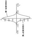
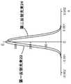
图2A和2B是示意性地示出在近场中作为距第一反射光束中心的距离的函数的、跨越图1B的第一和第二反射光束计算的电场幅度的曲线图,反射光束分别完全异相和完全同相。FIGS. 2A and 2B are graphs schematically showing the magnitude of the electric field calculated across the first and second reflected beams of FIG. 1B as a function of distance from the center of the first reflected beam in the near field, the reflected beams respectively fully Out of phase and exactly in phase.
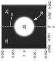
图3A、图3B和图3C是示意性示出图1B的检测器段上的干涉图案的计算的二维空间强度分布的图像,第一和第二反射光束分别完全异相、略微异相和完全同相。Figures 3A, 3B, and 3C are images schematically illustrating the calculated two-dimensional spatial intensity distribution of the interference pattern on the detector segment of Figure IB, the first and second reflected beams being completely out of phase, slightly out of phase, and Exactly in phase.
图4是示意性示出作为激光束波长漂移的函数的从图1B的检测器段的输出信号导出的差、总和误差信号的曲线图。Figure 4 is a graph schematically showing difference, summation error signals derived from the output signal of the detector segment of Figure IB as a function of laser beam wavelength drift.
图5示意性地示出了使用图1B的波长感测装置稳定的分布式反馈(DFB)二极管激光器,其中波长感测装置用在改变到DFB二极管激光器的驱动电流的闭合控制回路中。Figure 5 schematically illustrates a distributed feedback (DFB) diode laser stabilized using the wavelength sensing device of Figure IB used in a closed control loop to vary the drive current to the DFB diode laser.
图6是示意性地示出在有和没有来自本发明的波长感测装置的反馈的情况下图5的DFB二极管激光器的实施例的作为频率的函数的误差信号的曲线图。Figure 6 is a graph schematically showing the error signal as a function of frequency for the embodiment of the DFB diode laser of Figure 5 with and without feedback from the wavelength sensing device of the present invention.
图7示意性地示出了使用图1B的波长感测装置稳定的光泵浦半导体(OPS)激光器,其中波长感测装置用在改变OPS激光器的谐振器长度的闭合控制回路中。Figure 7 schematically illustrates an optically pumped semiconductor (OPS) laser stabilized using the wavelength sensing device of Figure IB, where the wavelength sensing device is used in a closed control loop that varies the resonator length of the OPS laser.
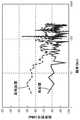
图8是示意性地示出在有和没有来自本发明的波长感测装置的反馈的情况下图7的OPS激光器的实施例的作为频率的函数的误差信号的曲线图。Figure 8 is a graph schematically showing the error signal as a function of frequency for the embodiment of the OPS laser of Figure 7 with and without feedback from the wavelength sensing device of the present invention.
发明详述Detailed description of the invention
现在转向附图,其中相同的特征由相同的附图标记表示。图1A示意性地示出了根据本发明的波长感测(频率感测)装置的优选实施方案10,用于跟踪激光辐射束12中的波长偏移(频移)。描述笛卡尔轴以供参考,其中x轴为和y轴任意指派。z轴是激光束12的传播轴。装置10包括位于激光束12中并相对于激光束12倾斜的非双折射标准具14。标准具14的法线16以角度θ相对于激光束12的传播轴倾斜。标准具14具有平行的平面第一表面18和平面第二表面20。标准具可由对激光辐射透明的任何玻璃或晶体制成,前提是标准具不表现出双折射。举例来说,标准具14具有在大约0.1mm至大约2.0mm之间的范围内的厚度T。角度θ在大约1度至大约10度之间的范围内。标准具14在激光束12中的精确位置并不重要,尽管标准具优选地位于光束的腰部附近,因此激光束在标准具中准直或接近准直。Turning now to the drawings, wherein like features are designated by like reference numerals. FIG. 1A schematically shows a
相对于激光束12倾斜标准具14导致第一光束22和第二光束24分别从第一表面18和第二表面20反射。如图所示,这两个反射束彼此平行传播,并在分段光电检测器30的接收表面28上形成干涉图案26。在下文中详细讨论干涉图案26。分段光电检测器30具有第一检测器段32和第二检测器段34。在装置10中,检测器段32和34通过隔离屏障36电分离。合适的分段光电检测器是型号SD066-24-21-011-ND两电池光电二极管,可从明尼苏达州ThiefRiver Falls的Digi-Key Electronics获得。Tilting the
对于本领域技术人员来说显而易见的是,会有来自标准具的其他反射光束。在图1A中描绘了第三个这样的反射光束38和对应的透射光束40。第三反射光束38中的辐射强度比第一反射光束22和第二反射光束24中的辐射强度小至少两个数量级。因此,第三反射光束38和随后的反射光束对干涉图案没有显著贡献。因此,在本发明的波长感测装置的进一步图中仅描绘了反射光束22和24。然而,这里描述和讨论的计算基本上包括所有反射光束。It will be apparent to those skilled in the art that there will be other reflected beams from the etalon. A third such reflected beam 38 and corresponding transmitted
在图1A中,为简化说明,每个光束由光束的传播轴描绘。然而,标准具通过具有横截面的光束之间的光学干涉来操作。图1B示意性地示出了图1A的波长感测装置10,激光束12(阴影)和反射光束22和24(斜阴影线)被描绘为在它们各自的外围光线之间空间延伸。反射光束22和24在体积42(交叉影线)中空间重叠并在接收表面28上形成干涉图案26。图中的光束是高度准直的。然而,应该注意的是,当标准具位于激光束的腰部附近时,衍射将进一步传播穿过分段光电检测器的反射光束。In Figure 1A, each beam is depicted by the beam's propagation axis for simplicity of illustration. However, etalons operate by optical interference between beams with cross-sections. Figure IB schematically illustrates the
分段光电检测器30位于距标准具的距离D处,标准具在反射光束的远场中。优选地,距离D是反射光束瑞利(Rayleigh)范围的至少四分之一。任选地,可以使用正透镜来聚焦反射光束,从而缩短距离D。根据本文中的本发明描述,本领域技术人员可以容易地凭经验确定最佳距离D。The
图2A是示意性地示出当反射光束完全异相时,在近场中作为距第一反射光束中心的距离x的函数的、跨越图1B的第一反射光束22和第二反射光束24计算的电场幅度的曲线图。在计算中,标准具位于激光束的腰部。该标准具由熔融石英制成,厚度T为1毫米,在1064纳米(nm)的激光波长下具有103GHz(相当于390pm)的自由光谱范围。倾斜角θ为5°。由于标准具的倾斜导致反射光束中心之间的轻微偏移,电场分布并不完全重叠。由于第二光束遇到标准具的两个表面时的额外损耗,第二反射光束24的负峰值的幅度比第一反射光束22的正峰值的幅度小约4%。Figure 2A is a schematic illustration of the computations across the first reflected
图3A是示意性示出当如图2A所示反射光束完全异相时,由图1B的接收表面28上的反射光束形成的干涉图案26的计算强度的图像。在计算中,分段光电检测器30位于距标准具14大约一个瑞利范围的位置。干涉图案包括两个相对暗的波瓣44A和44B。由于反射光束的不精确重叠,波瓣是可见的。在波瓣44A和44B之间是暗条纹46。分段光电检测器优选地布置成使得屏障36(由虚线指示)沿着暗条纹46的中心对齐。即,干涉图案的波瓣入射在不同的检测器段,并且屏障36对齐在波瓣之间的中间。反射光束完全异相的激光束12的波长对应于干涉反射光束的最小总强度。Figure 3A is an image schematically showing the calculated intensity of the
图3B是干涉图案26的图像,类似于图3A,但反射光束略微异相。此处,激光束12具有大约1064nm的波长,其与图3A的完全异相波长相位移大约0.0085nm。随着激光束的波长漂移而偏离完全异相状态,波瓣44A和44B之一将变得更大且更亮,而另一个将变得更小且更暗。暗条纹46将在x方向上跨越干涉图案漂移,并且当反射光束完全同相时将消失。在图。在图3B中,波瓣44B更大且更亮,而边缘46已向左漂移。Figure 3B is an image of an
如果激光束的波长继续漂移,则干涉图案变成以屏障36为中心的大亮点48。图2B和3C中描绘了这种完全同相的情况。图2A和图2B以及图3A-3C一起说明了干涉图案26如何取决于反射光束22和24之间的相位关系。If the wavelength of the laser beam continues to drift, the interference pattern becomes a large
检测器段32和34分别产生第一和第二输出信号。通过将这两个输出信号之间的差值除以这两个输出信号的总和得出误差信号。该误差信号是激光束波长与对应于完全异相的两个反射光束的波长(标准具波长)之间的差的函数。这些信号在图4中示出,图4是作为激光束波长的函数的计算的差值信号(按10倍缩放)、总信号和误差信号的曲线图。在计算中,激光束12具有1瓦特(W)的功率。在曲线图中,差信号和总信号被描绘为入射在光电检测器30的检测器段上的光功率瓦特。该曲线图指示激光束波长与标准具波长的位移。
输出信号的变化对应于激光束波长的变化。信号处理器(图1A和1B中未示出)可以被布置为接收输出信号并确定与输出信号的误差信号。误差信号表示反射光束22和24之间的相位关系。误差信号可用于改变激光束12的波长响应的参数的闭合控制回路中,以将误差信号保持为零或接近于零,从而将激光束的波长稳定到标准具波长。例如,激光器参数可以是谐振器长度、泵浦功率或产生激光束的激光器中的调谐元件。Changes in the output signal correspond to changes in the wavelength of the laser beam. A signal processor (not shown in FIGS. 1A and 1B ) may be arranged to receive the output signal and determine an error signal with the output signal. The error signal represents the phase relationship between the reflected beams 22 and 24 . The error signal can be used in a closed control loop that varies the parameters of the wavelength response of the
图5示意性地示出了使用图1B的波长感测装置10的波长稳定二极管激光器装置50。装置50包括分布式反馈(DFB)二极管激光器52。DFB二极管激光器可以作为封装在商业上采购,具有提供并入激光谐振器(未示出)中的分布式反馈的周期性结构。驱动电流由电流源(激光驱动器)54提供给DFB二极管激光器52。由驱动电流激励的DFB二极管激光器传送指定为激光辐射束12的输出光束,图1A中的与波长感测装置10的描述一致。波长感测装置10显然在DFB二极管激光器52的谐振器之外。Figure 5 schematically illustrates a wavelength stabilized
与DFB二极管激光器52并联连接的电流旁路由与负载电阻器R1串联的PNP双极晶体管T1形成。旁路电流流经电阻器R1并流经发射极E和集电极C之间的T1。装置10用在闭合控制回路中,该回路改变到DFB二极管激光器52的驱动电流。来自标准具14的干涉反射光束22和24入射到分段光电检测器30,其中分段光电检测器30的检测器段32和34象征性地表示为单独的光电二极管。检测器段32和34电连接到控制器56,控制器56包括确定误差信号的信号处理器,如上文参考图4所述。这里,误差信号是施加在晶体管T1的基极B上的电压,它相应地改变通过电流旁路的电流。这进而改变通过DFB二极管激光器52的互补驱动电流。如本领域中已知的,通过改变二极管激光器结处的温度,改变通过DFB二极管的驱动电流会改变激光束12的波长。A current bypass connected in parallel with the
图6示意性地示出了作为频率的函数的图5的波长稳定二极管激光器装置50的一个实施例中的测量误差信号。此处的误差信号缩放至20伏(V),并假设有50欧姆的电气负载。20V对应于假设的干涉图案,它用所有光功率照射仅一个光电检测器段。这些本质上是功率谱,说明了激光束的波长(频率)中的噪声。举例来说,波长的正弦调制将表现为正弦调制频率处的功率谱中的峰值。对于DFB二极管激光器52,使用波长感测装置10,相对于标准具波长测量激光束的波长。在图6中,相对噪声频谱是在有和没有来自本发明的波长感测装置的反馈的情况下测量的;即DFB二极管激光器的波长稳定和不稳定的情况。当不稳定时,通电的DFB二极管激光器自由运行。Figure 6 schematically shows the measurement error signal in one embodiment of the wavelength stabilized
在该实施例中,DFB二极管激光器52是可从瑞士苏黎世的II-VI LaserEnterprise GmbH获得的型号CMDFB1064A。这种DFB二极管激光器的标称输出波长为1064nm。分段光电检测器30是如上例示的型号SD066-24-21-011-ND。装置10的标准具14是厚度T为0.3mm的熔融石英标准具。标准具以大约5°的角度相对于激光束12倾斜。标准具14和分段光电检测器30之间的距离D约为500mm。In this embodiment, the
可以看出,对于小于约10Hz的频率,稳定(有反馈)时的相对噪声比不稳定(无反馈)时的相对噪声小约25分贝(dBm)。在大约10Hz和100Hz之间的频率下,由于二极管激光器结处的热响应时间为几百毫秒,稳定时和不稳定时的噪声频谱之间的差异逐渐变小。本质上,二极管激光器的热惯性抑制了所需的高频反馈调制。It can be seen that for frequencies less than about 10 Hz, the relative noise when stable (with feedback) is about 25 decibels (dBm) less than the relative noise when unstable (without feedback). At frequencies between about 10 Hz and 100 Hz, the difference between stable and unstable noise spectra becomes progressively smaller due to the thermal response time at the diode laser junction of several hundred milliseconds. Essentially, the thermal inertia of the diode laser suppresses the desired high frequency feedback modulation.
图7示意性地示出了使用图1B的波长感测装置10稳定的光泵浦半导体(OPS)激光器60。OPS激光器60包括OPS芯片62,其具有覆盖高反射镜结构66的半导体增益结构64。OPS芯片结合到散热器68。增益结构64通过光泵浦激励,这里是通过由二极管激光器阵列(未显示)供给的泵浦辐射P。OPS激光器60具有在OPS芯片62的高反射镜结构66和安装在PZT 74上的部分透射输出耦合镜72之间形成的线性谐振器70。响应于光泵浦,具有基本波长的激光辐射束在谐振器70中循环,如箭头F所示。输出激光辐射束76透射通过输出耦合镜72。通常,双折射滤波器78提供粗略的波长选择(频率选择)。Figure 7 schematically illustrates an optically pumped semiconductor (OPS)
此处,装置10的标准具14位于双折射滤波器78和输出耦合镜72之间的谐振器70中。谐振器内的循环激光束与图1B的激光束12相当,不同之处在于谐振器中的循环激光束是双向的。来自标准具14的反射光束22和24在分段光电检测器30的检测器段32和34上形成干涉图案26,如上面参考图1A、图1B、图3A、图3B和图3C所述。任选的透镜80可以位于标准具和光电检测器之间的反射光束中,以缩短到检测器的距离,如上所述,并缩小入射在光电检测器上的干涉光束。Here, the
检测器段32和34电连接到控制器56,控制器56包括信号处理器以从检测器段的输出信号导出误差信号,如上所述。这里,控制器向PZT 74施加响应误差信号的电压。施加的电压会改变谐振器的长度,从而改变循环激光束F的波长(频率)。该闭合控制回路将误差信号保持为零或接近于零。
应当注意,这里仅提供了对OPS激光器60的充分描述以用于理解本发明的原理。转让给本发明的受让人的美国专利第6,097,742号中提供了对OPS激光器的详细描述,包括几种不同的谐振器配置,在此通过引用将其完整公开内容并入本文。It should be noted that a sufficient description of the
图8示意性地示出了作为频率的函数的图7的OPS激光器60的一个实施例中的测量误差信号。同样,这些基本上是激光束波长中噪声的功率谱,在有和没有来自本发明的波长感测装置的反馈的情况下测量。在该实施例中,OPS激光器被布置成以大约1064nm的波长传送输出激光束76。谐振器长度为130mm。PZT 74是一种PK25LA2P2型圆形PZT堆叠,可从新泽西州牛顿的Thorlabs获得。分段光电检测器30是如上例示的型号SD066-24-21-011-ND光电二极管。标准具14由熔融石英制成,厚度为1mm。标准具以大约5度的角度相对于循环激光束倾斜。从标准具到分段光电检测器30的距离约为500mm。透镜80具有大约250mm的焦距并且被包括以在分段光电检测器30的物理尺寸内适合入射光束。如果使用了更大的光电检测器,则可以省略该透镜。Figure 8 schematically illustrates the measurement error signal in one embodiment of the
从图8可以看出,与没有反馈相比,有反馈情况下的相对噪声最大降低25到30dB与图6类似。然而,对于图8的OPS激光器,这种降低保持在几千赫兹。在较高频率下,由于PZT致动反射镜的机械敏捷性减弱,噪声频谱开始收敛。本质上,PZT致动反射镜的机械共振会扭曲更高频率的反馈调制。在单独的实验中,使用具有约340mm谐振器长度的不同OPS激光器,噪声的最大降低保持在约10KHz。As can be seen from Figure 8, the relative noise reduction with feedback is a maximum of 25 to 30 dB compared to without feedback, similar to Figure 6. However, for the OPS laser of Figure 8, this reduction remains at a few kilohertz. At higher frequencies, the noise spectrum begins to converge due to the diminished mechanical agility of the PZT-actuated mirrors. Essentially, the mechanical resonance of the PZT-actuated mirror distorts the higher frequency feedback modulation. In separate experiments, using different OPS lasers with a resonator length of about 340 mm, the maximum reduction in noise was kept at about 10 KHz.
在以上提供的描述中,本发明的波长感测装置和方法应用于具有线性谐振器的DFB二极管激光器和OPS激光器。然而,本发明的波长感测装置对于其他类型的固态激光器以及具有环形谐振器的激光器都是有效的。对于产生足够输出功率的固态激光器,本发明的波长感测装置可以部署在谐振器外部,如图5对于DFB二极管激光器所示。本发明的波长感测装置也可用于腔内变频激光器。In the description provided above, the wavelength sensing apparatus and method of the present invention are applied to DFB diode lasers and OPS lasers with linear resonators. However, the wavelength sensing device of the present invention is effective for other types of solid state lasers as well as lasers with ring resonators. For solid-state lasers producing sufficient output power, the wavelength sensing device of the present invention can be deployed outside the resonator, as shown in Figure 5 for a DFB diode laser. The wavelength sensing device of the present invention can also be used in intracavity frequency conversion lasers.
由于热膨胀系数和制造标准具的透明材料的折射率的温度依赖性,标准具波长通常与温度有关。标准具中的温度变化会改变标准具的厚度T以及标准具中的光学长度。为了保持恒定的波长,可能需要调节标准具的温度。替代地,为了调整激光器的输出波长,可以有意改变标准具的温度。本发明的闭合控制回路中的波长感测装置将通过连续地最小化误差信号来调谐波长。The etalon wavelength is generally temperature dependent due to the temperature dependence of the coefficient of thermal expansion and the refractive index of the transparent material from which the etalon is made. Temperature changes in the etalon change the thickness T of the etalon as well as the optical length in the etalon. In order to maintain a constant wavelength, the temperature of the etalon may need to be adjusted. Alternatively, the temperature of the etalon can be intentionally changed in order to adjust the output wavelength of the laser. The wavelength sensing device in the closed control loop of the present invention will tune the wavelength by continuously minimizing the error signal.
在以上实施例中,分段光电检测器是具有被隔离屏障分隔的两个光电池的光电二极管,这是结合到本发明的波长感测装置中的方便的商业设备。替代地,分段光电检测器可以是光电二极管阵列或一对分立光电二极管,布置成使得每个光电二极管仅拦截干扰反射光束的一个波瓣。如图2B和图2D所示,分段光电检测器可以是照相机或其他成像设备,检测器段是图像的两半。将通过对图像的每一半进行积分来导出两个输出信号。In the above embodiments, the segmented photodetector is a photodiode with two photocells separated by an isolation barrier, which is a convenient commercial device to incorporate into the wavelength sensing device of the present invention. Alternatively, the segmented photodetector may be an array of photodiodes or a pair of discrete photodiodes arranged such that each photodiode intercepts only one lobe of the interfering reflected beam. As shown in Figures 2B and 2D, the segmented photodetectors may be cameras or other imaging devices, and the detector segments are the two halves of the image. Two output signals will be derived by integrating each half of the image.
总之,发现将标准具放置在激光束中并相对于激光束倾斜,会在从标准具反射的光束的远场中形成干涉图案。这种干涉图案可以被引导到分段光电检测器上,以获得与激光束波长相对应的误差信号。这使得标准具和分段光电检测器能够用作波长传感器。误差信号可用于闭合控制回路以最小化激光束的波长漂移。这在上面描述并且在两种类型的激光器中不同地部署。建议了本发明适用的其他激光器类型。与需要几个相对昂贵的光学组件的现有技术波长稳定装置不同,本发明的波长传感器在最简单的形式中仅需要一个额外的光学元件,即未涂覆且非双折射的标准具。这样的标准具可以以相对低的成本以相对大的批量制造。In summary, it was found that placing the etalon in the laser beam and tilting it relative to the laser beam creates an interference pattern in the far field of the beam reflected from the etalon. This interference pattern can be directed onto a segmented photodetector to obtain an error signal corresponding to the wavelength of the laser beam. This enables etalons and segmented photodetectors to be used as wavelength sensors. The error signal can be used to close the control loop to minimize wavelength drift of the laser beam. This is described above and deployed differently in the two types of lasers. Other laser types for which the present invention is applicable are suggested. Unlike prior art wavelength stabilization devices that require several relatively expensive optical components, the wavelength sensor of the present invention, in its simplest form, requires only one additional optical element, an uncoated and non-birefringent etalon. Such etalons can be manufactured in relatively large quantities at relatively low cost.
本发明在此被描述为部署在两种类型激光器的实施例中的优选实施方案。然而,应当注意,本发明不受本文描述和描绘的优选实施方案和实施例的限制。相反,本发明仅受所附权利要求的限制。The invention is described herein as a preferred embodiment deployed in embodiments of both types of lasers. It should be noted, however, that the present invention is not limited by the preferred embodiments and examples described and depicted herein. Rather, the invention is limited only by the appended claims.
Claims (20)
Applications Claiming Priority (3)
| Application Number | Priority Date | Filing Date | Title |
|---|---|---|---|
| US16/518,689 | 2019-07-22 | ||
| US16/518,689US11283237B2 (en) | 2019-07-22 | 2019-07-22 | Laser wavelength stabilization apparatus |
| PCT/US2020/042011WO2021016004A1 (en) | 2019-07-22 | 2020-07-14 | Laser wavelength stabilization apparatus |
Publications (2)
| Publication Number | Publication Date |
|---|---|
| CN114424416Atrue CN114424416A (en) | 2022-04-29 |
| CN114424416B CN114424416B (en) | 2025-06-27 |
Family
ID=71944376
Family Applications (1)
| Application Number | Title | Priority Date | Filing Date |
|---|---|---|---|
| CN202080052730.XAActiveCN114424416B (en) | 2019-07-22 | 2020-07-14 | Laser wavelength stabilizing device |
Country Status (4)
| Country | Link |
|---|---|
| US (1) | US11283237B2 (en) |
| EP (1) | EP4005040A1 (en) |
| CN (1) | CN114424416B (en) |
| WO (1) | WO2021016004A1 (en) |
Citations (7)
| Publication number | Priority date | Publication date | Assignee | Title |
|---|---|---|---|---|
| US5825792A (en)* | 1996-07-11 | 1998-10-20 | Northern Telecom Limited | Wavelength monitoring and control assembly for WDM optical transmission systems |
| US20010022793A1 (en)* | 2000-03-10 | 2001-09-20 | Nec Corporation | Wavelength stabilized laser module |
| US20020181519A1 (en)* | 2001-05-31 | 2002-12-05 | Altitun Ab | Apparatus and method for controlling the operating wavelength of a laser |
| JP2003264339A (en)* | 2002-03-08 | 2003-09-19 | Furukawa Electric Co Ltd:The | Semiconductor laser module and wavelength locker module |
| US20080317076A1 (en)* | 2007-06-21 | 2008-12-25 | Fujitsu Limited Of Kawasaki, Japan | Controlling output wavelength of a light source |
| CN101630814A (en)* | 2008-11-17 | 2010-01-20 | 高培良 | Low profile high performance wavelength tunable laser |
| US20120147361A1 (en)* | 2010-12-13 | 2012-06-14 | Mitsubishi Electric Corporation | Wavelength monitor |
Family Cites Families (12)
| Publication number | Priority date | Publication date | Assignee | Title |
|---|---|---|---|---|
| US4564289A (en)* | 1984-07-31 | 1986-01-14 | Geo-Centers, Inc. | Single mode optical fiber polarimetric stress sensor having optical common mode rejection |
| JPS61202128A (en)* | 1985-03-06 | 1986-09-06 | Hitachi Ltd | Semiconductor laser heterodyne interferometer |
| US5003546A (en)* | 1989-08-31 | 1991-03-26 | At&T Bell Laboratories | Interferometric devices for reducing harmonic distortions in laser communication systems |
| US5537432A (en)* | 1993-01-07 | 1996-07-16 | Sdl, Inc. | Wavelength-stabilized, high power semiconductor laser |
| US6205159B1 (en) | 1997-06-23 | 2001-03-20 | Newport Corporation | Discrete wavelength liquid crystal tuned external cavity diode laser |
| US6097742A (en) | 1999-03-05 | 2000-08-01 | Coherent, Inc. | High-power external-cavity optically-pumped semiconductor lasers |
| JP2002252413A (en) | 2001-02-26 | 2002-09-06 | Hitachi Ltd | Semiconductor laser module and optical system using the same |
| US6621580B2 (en)* | 2001-05-08 | 2003-09-16 | Precision Photonics Corporation | Single etalon wavelength locker |
| US7075656B2 (en) | 2001-12-11 | 2006-07-11 | Adc Telecommunications, Inc. | Method and algorithm for continuous wavelength locking |
| US6965622B1 (en)* | 2002-01-28 | 2005-11-15 | Ciena Corporation | Wavelength locking scheme and algorithm for ultra-high density WDM system |
| US7061946B2 (en) | 2002-11-13 | 2006-06-13 | Intel Corporation | Intra-cavity etalon with asymmetric power transfer function |
| DE10260183A1 (en)* | 2002-12-20 | 2004-07-15 | Osram Opto Semiconductors Gmbh | Vertically emitting optically pumped semiconductor laser with external resonator and semiconductor body with quantum trough structure as active zone with intertrough barriers |
- 2019
- 2019-07-22USUS16/518,689patent/US11283237B2/enactiveActive
- 2020
- 2020-07-14WOPCT/US2020/042011patent/WO2021016004A1/ennot_activeCeased
- 2020-07-14CNCN202080052730.XApatent/CN114424416B/enactiveActive
- 2020-07-14EPEP20750981.1Apatent/EP4005040A1/enactivePending
Patent Citations (7)
| Publication number | Priority date | Publication date | Assignee | Title |
|---|---|---|---|---|
| US5825792A (en)* | 1996-07-11 | 1998-10-20 | Northern Telecom Limited | Wavelength monitoring and control assembly for WDM optical transmission systems |
| US20010022793A1 (en)* | 2000-03-10 | 2001-09-20 | Nec Corporation | Wavelength stabilized laser module |
| US20020181519A1 (en)* | 2001-05-31 | 2002-12-05 | Altitun Ab | Apparatus and method for controlling the operating wavelength of a laser |
| JP2003264339A (en)* | 2002-03-08 | 2003-09-19 | Furukawa Electric Co Ltd:The | Semiconductor laser module and wavelength locker module |
| US20080317076A1 (en)* | 2007-06-21 | 2008-12-25 | Fujitsu Limited Of Kawasaki, Japan | Controlling output wavelength of a light source |
| CN101630814A (en)* | 2008-11-17 | 2010-01-20 | 高培良 | Low profile high performance wavelength tunable laser |
| US20120147361A1 (en)* | 2010-12-13 | 2012-06-14 | Mitsubishi Electric Corporation | Wavelength monitor |
Also Published As
| Publication number | Publication date |
|---|---|
| WO2021016004A1 (en) | 2021-01-28 |
| EP4005040A1 (en) | 2022-06-01 |
| CN114424416B (en) | 2025-06-27 |
| US20210028599A1 (en) | 2021-01-28 |
| US11283237B2 (en) | 2022-03-22 |
Similar Documents
| Publication | Publication Date | Title |
|---|---|---|
| US7701984B2 (en) | Laser module and method of controlling wavelength of external cavity laser | |
| EP0514758B1 (en) | Laser light generator | |
| US6611546B1 (en) | Optical transmitter comprising a stepwise tunable laser | |
| US6711203B1 (en) | Optical transmitter comprising a stepwise tunable laser | |
| JP3979703B2 (en) | Wavelength monitoring controller for wavelength division multiplexing optical transmission system | |
| US6741629B1 (en) | Optical transmitter having optically pumped vertical external cavity surface emitting laser | |
| EP1744414A2 (en) | Frequency-stabilized laser and frequency stabilizing method | |
| US20060193354A1 (en) | External Cavity Tunable Laser and Control | |
| US20120025714A1 (en) | High-stability light source system and method of manufacturing | |
| WO2011120246A1 (en) | Tunable laser | |
| CA2343087A1 (en) | Tunable laser and method for operating the same | |
| US6594289B2 (en) | Tunable laser source apparatus | |
| US5956356A (en) | Monitoring wavelength of laser devices | |
| US20040258109A1 (en) | Solid laser apparatus | |
| JP6902749B2 (en) | Tunable laser device and control method for tunable laser | |
| JP3811184B2 (en) | Transversely pumped solid-state laser | |
| EP0390525B1 (en) | An optical pumping-type solid-state laser apparatus with a semiconductor laser device | |
| JP6541241B2 (en) | Optically pumped semiconductor laser with mode tracking | |
| CN114424416B (en) | Laser wavelength stabilizing device | |
| EP1427077A2 (en) | External cavity laser having improved single mode operation | |
| EP1364432A2 (en) | Optical transmitter comprising a stepwise tunable laser | |
| JP3767318B2 (en) | LD pumped solid state laser device | |
| JP2005529497A (en) | Tunable ring resonator | |
| JP2004356505A (en) | External cavity laser with improved single mode operation | |
| JP2017135252A (en) | Light-emitting module |
Legal Events
| Date | Code | Title | Description |
|---|---|---|---|
| PB01 | Publication | ||
| PB01 | Publication | ||
| SE01 | Entry into force of request for substantive examination | ||
| SE01 | Entry into force of request for substantive examination | ||
| GR01 | Patent grant | ||
| GR01 | Patent grant |