CN114423360A - Magnetic anastomosis device with embedded drainage mechanism - Google Patents
Magnetic anastomosis device with embedded drainage mechanismDownload PDFInfo
- Publication number
- CN114423360A CN114423360ACN202080042576.8ACN202080042576ACN114423360ACN 114423360 ACN114423360 ACN 114423360ACN 202080042576 ACN202080042576 ACN 202080042576ACN 114423360 ACN114423360 ACN 114423360A
- Authority
- CN
- China
- Prior art keywords
- coil
- wire
- magnets
- anastomosis
- present specification
- Prior art date
- Legal status (The legal status is an assumption and is not a legal conclusion. Google has not performed a legal analysis and makes no representation as to the accuracy of the status listed.)
- Granted
Links
Images


Classifications
- A—HUMAN NECESSITIES
- A61—MEDICAL OR VETERINARY SCIENCE; HYGIENE
- A61B—DIAGNOSIS; SURGERY; IDENTIFICATION
- A61B17/00—Surgical instruments, devices or methods
- A61B17/11—Surgical instruments, devices or methods for performing anastomosis; Buttons for anastomosis
- A61B17/1114—Surgical instruments, devices or methods for performing anastomosis; Buttons for anastomosis of the digestive tract, e.g. bowels or oesophagus
- A—HUMAN NECESSITIES
- A61—MEDICAL OR VETERINARY SCIENCE; HYGIENE
- A61B—DIAGNOSIS; SURGERY; IDENTIFICATION
- A61B18/00—Surgical instruments, devices or methods for transferring non-mechanical forms of energy to or from the body
- A61B18/04—Surgical instruments, devices or methods for transferring non-mechanical forms of energy to or from the body by heating
- A61B18/08—Surgical instruments, devices or methods for transferring non-mechanical forms of energy to or from the body by heating by means of electrically-heated probes
- A61B18/082—Probes or electrodes therefor
- A—HUMAN NECESSITIES
- A61—MEDICAL OR VETERINARY SCIENCE; HYGIENE
- A61B—DIAGNOSIS; SURGERY; IDENTIFICATION
- A61B17/00—Surgical instruments, devices or methods
- A61B2017/00526—Methods of manufacturing
- A—HUMAN NECESSITIES
- A61—MEDICAL OR VETERINARY SCIENCE; HYGIENE
- A61B—DIAGNOSIS; SURGERY; IDENTIFICATION
- A61B17/00—Surgical instruments, devices or methods
- A61B2017/00681—Aspects not otherwise provided for
- A61B2017/00725—Calibration or performance testing
- A—HUMAN NECESSITIES
- A61—MEDICAL OR VETERINARY SCIENCE; HYGIENE
- A61B—DIAGNOSIS; SURGERY; IDENTIFICATION
- A61B17/00—Surgical instruments, devices or methods
- A61B2017/00831—Material properties
- A61B2017/00867—Material properties shape memory effect
- A—HUMAN NECESSITIES
- A61—MEDICAL OR VETERINARY SCIENCE; HYGIENE
- A61B—DIAGNOSIS; SURGERY; IDENTIFICATION
- A61B17/00—Surgical instruments, devices or methods
- A61B2017/00831—Material properties
- A61B2017/00876—Material properties magnetic
- A—HUMAN NECESSITIES
- A61—MEDICAL OR VETERINARY SCIENCE; HYGIENE
- A61B—DIAGNOSIS; SURGERY; IDENTIFICATION
- A61B17/00—Surgical instruments, devices or methods
- A61B2017/00831—Material properties
- A61B2017/00929—Material properties isolating electrical current
- A—HUMAN NECESSITIES
- A61—MEDICAL OR VETERINARY SCIENCE; HYGIENE
- A61B—DIAGNOSIS; SURGERY; IDENTIFICATION
- A61B17/00—Surgical instruments, devices or methods
- A61B17/11—Surgical instruments, devices or methods for performing anastomosis; Buttons for anastomosis
- A61B17/1114—Surgical instruments, devices or methods for performing anastomosis; Buttons for anastomosis of the digestive tract, e.g. bowels or oesophagus
- A61B2017/1117—Surgical instruments, devices or methods for performing anastomosis; Buttons for anastomosis of the digestive tract, e.g. bowels or oesophagus adapted for discharge after necrotisation, e.g. by evacuation, expulsion or excretion
- A—HUMAN NECESSITIES
- A61—MEDICAL OR VETERINARY SCIENCE; HYGIENE
- A61B—DIAGNOSIS; SURGERY; IDENTIFICATION
- A61B17/00—Surgical instruments, devices or methods
- A61B17/11—Surgical instruments, devices or methods for performing anastomosis; Buttons for anastomosis
- A61B2017/1132—End-to-end connections
- A—HUMAN NECESSITIES
- A61—MEDICAL OR VETERINARY SCIENCE; HYGIENE
- A61B—DIAGNOSIS; SURGERY; IDENTIFICATION
- A61B17/00—Surgical instruments, devices or methods
- A61B17/11—Surgical instruments, devices or methods for performing anastomosis; Buttons for anastomosis
- A61B2017/1139—Side-to-side connections, e.g. shunt or X-connections
- A—HUMAN NECESSITIES
- A61—MEDICAL OR VETERINARY SCIENCE; HYGIENE
- A61B—DIAGNOSIS; SURGERY; IDENTIFICATION
- A61B18/00—Surgical instruments, devices or methods for transferring non-mechanical forms of energy to or from the body
- A61B2018/00053—Mechanical features of the instrument of device
- A61B2018/00107—Coatings on the energy applicator
- A61B2018/00136—Coatings on the energy applicator with polymer
- A—HUMAN NECESSITIES
- A61—MEDICAL OR VETERINARY SCIENCE; HYGIENE
- A61B—DIAGNOSIS; SURGERY; IDENTIFICATION
- A61B18/00—Surgical instruments, devices or methods for transferring non-mechanical forms of energy to or from the body
- A61B2018/00315—Surgical instruments, devices or methods for transferring non-mechanical forms of energy to or from the body for treatment of particular body parts
- A61B2018/00482—Digestive system
- A61B2018/00494—Stomach, intestines or bowel
- A—HUMAN NECESSITIES
- A61—MEDICAL OR VETERINARY SCIENCE; HYGIENE
- A61B—DIAGNOSIS; SURGERY; IDENTIFICATION
- A61B18/00—Surgical instruments, devices or methods for transferring non-mechanical forms of energy to or from the body
- A61B2018/00315—Surgical instruments, devices or methods for transferring non-mechanical forms of energy to or from the body for treatment of particular body parts
- A61B2018/00529—Liver
- A61B2018/00535—Biliary tract
- A—HUMAN NECESSITIES
- A61—MEDICAL OR VETERINARY SCIENCE; HYGIENE
- A61B—DIAGNOSIS; SURGERY; IDENTIFICATION
- A61B18/00—Surgical instruments, devices or methods for transferring non-mechanical forms of energy to or from the body
- A61B2018/00571—Surgical instruments, devices or methods for transferring non-mechanical forms of energy to or from the body for achieving a particular surgical effect
- A61B2018/00601—Cutting
- A—HUMAN NECESSITIES
- A61—MEDICAL OR VETERINARY SCIENCE; HYGIENE
- A61B—DIAGNOSIS; SURGERY; IDENTIFICATION
- A61B18/00—Surgical instruments, devices or methods for transferring non-mechanical forms of energy to or from the body
- A61B18/04—Surgical instruments, devices or methods for transferring non-mechanical forms of energy to or from the body by heating
- A61B18/12—Surgical instruments, devices or methods for transferring non-mechanical forms of energy to or from the body by heating by passing a current through the tissue to be heated, e.g. high-frequency current
- A61B18/14—Probes or electrodes therefor
- A61B2018/1405—Electrodes having a specific shape
- A61B2018/1407—Loop
- A—HUMAN NECESSITIES
- A61—MEDICAL OR VETERINARY SCIENCE; HYGIENE
- A61B—DIAGNOSIS; SURGERY; IDENTIFICATION
- A61B18/00—Surgical instruments, devices or methods for transferring non-mechanical forms of energy to or from the body
- A61B18/04—Surgical instruments, devices or methods for transferring non-mechanical forms of energy to or from the body by heating
- A61B18/12—Surgical instruments, devices or methods for transferring non-mechanical forms of energy to or from the body by heating by passing a current through the tissue to be heated, e.g. high-frequency current
- A61B18/14—Probes or electrodes therefor
- A61B2018/1405—Electrodes having a specific shape
- A61B2018/144—Wire
- A—HUMAN NECESSITIES
- A61—MEDICAL OR VETERINARY SCIENCE; HYGIENE
- A61B—DIAGNOSIS; SURGERY; IDENTIFICATION
- A61B90/00—Instruments, implements or accessories specially adapted for surgery or diagnosis and not covered by any of the groups A61B1/00 - A61B50/00, e.g. for luxation treatment or for protecting wound edges
- A61B90/39—Markers, e.g. radio-opaque or breast lesions markers
- A61B2090/392—Radioactive markers
- A—HUMAN NECESSITIES
- A61—MEDICAL OR VETERINARY SCIENCE; HYGIENE
- A61B—DIAGNOSIS; SURGERY; IDENTIFICATION
- A61B90/00—Instruments, implements or accessories specially adapted for surgery or diagnosis and not covered by any of the groups A61B1/00 - A61B50/00, e.g. for luxation treatment or for protecting wound edges
- A61B90/90—Identification means for patients or instruments, e.g. tags
- A61B90/98—Identification means for patients or instruments, e.g. tags using electromagnetic means, e.g. transponders
- A—HUMAN NECESSITIES
- A61—MEDICAL OR VETERINARY SCIENCE; HYGIENE
- A61F—FILTERS IMPLANTABLE INTO BLOOD VESSELS; PROSTHESES; DEVICES PROVIDING PATENCY TO, OR PREVENTING COLLAPSING OF, TUBULAR STRUCTURES OF THE BODY, e.g. STENTS; ORTHOPAEDIC, NURSING OR CONTRACEPTIVE DEVICES; FOMENTATION; TREATMENT OR PROTECTION OF EYES OR EARS; BANDAGES, DRESSINGS OR ABSORBENT PADS; FIRST-AID KITS
- A61F2/00—Filters implantable into blood vessels; Prostheses, i.e. artificial substitutes or replacements for parts of the body; Appliances for connecting them with the body; Devices providing patency to, or preventing collapsing of, tubular structures of the body, e.g. stents
- A61F2/02—Prostheses implantable into the body
- A61F2/04—Hollow or tubular parts of organs, e.g. bladders, tracheae, bronchi or bile ducts
- A61F2/06—Blood vessels
- A61F2/064—Blood vessels with special features to facilitate anastomotic coupling
- A—HUMAN NECESSITIES
- A61—MEDICAL OR VETERINARY SCIENCE; HYGIENE
- A61F—FILTERS IMPLANTABLE INTO BLOOD VESSELS; PROSTHESES; DEVICES PROVIDING PATENCY TO, OR PREVENTING COLLAPSING OF, TUBULAR STRUCTURES OF THE BODY, e.g. STENTS; ORTHOPAEDIC, NURSING OR CONTRACEPTIVE DEVICES; FOMENTATION; TREATMENT OR PROTECTION OF EYES OR EARS; BANDAGES, DRESSINGS OR ABSORBENT PADS; FIRST-AID KITS
- A61F2/00—Filters implantable into blood vessels; Prostheses, i.e. artificial substitutes or replacements for parts of the body; Appliances for connecting them with the body; Devices providing patency to, or preventing collapsing of, tubular structures of the body, e.g. stents
- A61F2/82—Devices providing patency to, or preventing collapsing of, tubular structures of the body, e.g. stents
- A61F2/86—Stents in a form characterised by the wire-like elements; Stents in the form characterised by a net-like or mesh-like structure
- A61F2/88—Stents in a form characterised by the wire-like elements; Stents in the form characterised by a net-like or mesh-like structure the wire-like elements formed as helical or spiral coils
- A—HUMAN NECESSITIES
- A61—MEDICAL OR VETERINARY SCIENCE; HYGIENE
- A61F—FILTERS IMPLANTABLE INTO BLOOD VESSELS; PROSTHESES; DEVICES PROVIDING PATENCY TO, OR PREVENTING COLLAPSING OF, TUBULAR STRUCTURES OF THE BODY, e.g. STENTS; ORTHOPAEDIC, NURSING OR CONTRACEPTIVE DEVICES; FOMENTATION; TREATMENT OR PROTECTION OF EYES OR EARS; BANDAGES, DRESSINGS OR ABSORBENT PADS; FIRST-AID KITS
- A61F2230/00—Geometry of prostheses classified in groups A61F2/00 - A61F2/26 or A61F2/82 or A61F9/00 or A61F11/00 or subgroups thereof
- A61F2230/0002—Two-dimensional shapes, e.g. cross-sections
- A61F2230/0004—Rounded shapes, e.g. with rounded corners
- A61F2230/001—Figure-8-shaped, e.g. hourglass-shaped
- A—HUMAN NECESSITIES
- A61—MEDICAL OR VETERINARY SCIENCE; HYGIENE
- A61F—FILTERS IMPLANTABLE INTO BLOOD VESSELS; PROSTHESES; DEVICES PROVIDING PATENCY TO, OR PREVENTING COLLAPSING OF, TUBULAR STRUCTURES OF THE BODY, e.g. STENTS; ORTHOPAEDIC, NURSING OR CONTRACEPTIVE DEVICES; FOMENTATION; TREATMENT OR PROTECTION OF EYES OR EARS; BANDAGES, DRESSINGS OR ABSORBENT PADS; FIRST-AID KITS
- A61F2250/00—Special features of prostheses classified in groups A61F2/00 - A61F2/26 or A61F2/82 or A61F9/00 or A61F11/00 or subgroups thereof
- A61F2250/0014—Special features of prostheses classified in groups A61F2/00 - A61F2/26 or A61F2/82 or A61F9/00 or A61F11/00 or subgroups thereof having different values of a given property or geometrical feature, e.g. mechanical property or material property, at different locations within the same prosthesis
- A61F2250/0039—Special features of prostheses classified in groups A61F2/00 - A61F2/26 or A61F2/82 or A61F9/00 or A61F11/00 or subgroups thereof having different values of a given property or geometrical feature, e.g. mechanical property or material property, at different locations within the same prosthesis differing in diameter
- A—HUMAN NECESSITIES
- A61—MEDICAL OR VETERINARY SCIENCE; HYGIENE
- A61M—DEVICES FOR INTRODUCING MEDIA INTO, OR ONTO, THE BODY; DEVICES FOR TRANSDUCING BODY MEDIA OR FOR TAKING MEDIA FROM THE BODY; DEVICES FOR PRODUCING OR ENDING SLEEP OR STUPOR
- A61M2210/00—Anatomical parts of the body
- A61M2210/10—Trunk
- A61M2210/1042—Alimentary tract
- A61M2210/1075—Gall bladder
- A—HUMAN NECESSITIES
- A61—MEDICAL OR VETERINARY SCIENCE; HYGIENE
- A61M—DEVICES FOR INTRODUCING MEDIA INTO, OR ONTO, THE BODY; DEVICES FOR TRANSDUCING BODY MEDIA OR FOR TAKING MEDIA FROM THE BODY; DEVICES FOR PRODUCING OR ENDING SLEEP OR STUPOR
- A61M27/00—Drainage appliance for wounds or the like, i.e. wound drains, implanted drains
- A61M27/002—Implant devices for drainage of body fluids from one part of the body to another
Landscapes
- Health & Medical Sciences (AREA)
- Surgery (AREA)
- Life Sciences & Earth Sciences (AREA)
- Engineering & Computer Science (AREA)
- Biomedical Technology (AREA)
- Public Health (AREA)
- Nuclear Medicine, Radiotherapy & Molecular Imaging (AREA)
- Veterinary Medicine (AREA)
- General Health & Medical Sciences (AREA)
- Heart & Thoracic Surgery (AREA)
- Medical Informatics (AREA)
- Molecular Biology (AREA)
- Animal Behavior & Ethology (AREA)
- Physics & Mathematics (AREA)
- Otolaryngology (AREA)
- Plasma & Fusion (AREA)
- Physiology (AREA)
- Surgical Instruments (AREA)
Abstract
Translated fromChinese
Description
Translated fromChinese交叉引用cross reference
本申请要求2019年4月10日提交的标题为“具有嵌入式支架的磁性吻合装置”的美国临时专利申请第62/832,154号的优先权。This application claims priority to US Provisional Patent Application No. 62/832,154, filed April 10, 2019, entitled "Magnetic Anastomotic Device with Embedded Stent."
本申请也是2018年10月26日提交的标题为“磁性吻合装置和输送系统”的美国专利申请第16/171,779号的部分延续申请,该申请是2017年5月25日提交的相同标题的美国专利申请第15/605,286号的延续申请,并于2018年12月18日作为美国专利第10,154,844号发布,其依次依赖于2016年11月23日提交的标题为“吻合装置和输送系统”的美国专利临时申请第62/425,951号、2016年10月16日提交的标题为“吻合装置和输送系统”的美国专利临时申请第62/408,795号和2016年7月25日提交的标题为“吻合装置和输送系统”的美国专利临时申请第62/366,185号。This application is also a continuation-in-part of US Patent Application Serial No. 16/171,779, filed October 26, 2018, entitled "Magnetic Anastomotic Device and Delivery System," which is a continuation-in-part of US Patent Application No. 16/171,779, filed May 25, 2017, of the same title. Continuation of Patent Application No. 15/605,286 and issued on Dec. 18, 2018 as US Patent No. 10,154,844, which in turn relies on U.S. Patent Application No. 10,154,844, filed Nov. 23, 2016 Patent Provisional Application No. 62/425,951, U.S. Patent Provisional Application No. 62/408,795, filed Oct. 16, 2016, titled "Anastomotic Device and Delivery System," and filed Jul. 25, 2016, entitled "Anastomotic Device and Delivery System" US Patent Provisional Application No. 62/366,185.
所有上述申请的全部内容通过引用并入本文。The entire contents of all of the aforementioned applications are incorporated herein by reference.
技术领域technical field
本说明书涉及磁压缩吻合装置在人体内的放置,更具体地说,涉及一种磁压缩吻合形成装置,其包含在吻合术中在体内预定位置形成即时开放的机构。The present specification relates to the placement of a magnetic compression anastomosis device in the human body, and more particularly, to a magnetic compression anastomosis forming device comprising a mechanism for forming an instant opening at a predetermined location in the body during anastomosis.
背景技术Background technique
现有技术的用于形成吻合的装置通常包括穿刺尖端,该尖端有危险性,可能对邻近的器官造成伤害。这些器械通常使用可能难以操作的抓取机构。此外,一些现有技术中的器械的操作需要两次穿刺,这可能会增加经抓钳从穿刺部位泄漏的几率。此外,某些现有技术的装置只能与相邻的壁相对,而没有足够的压力导致介入组织的损伤和坏死以形成足够大的吻合,该吻合长时间保持开放以提供足够的引流。需要额外的介入来创造一个大的开口。虽然已知由诸如形状记忆合金(SMA)的材料制成的支架,其通过内窥镜插入人体内,用于形成吻合和排出胰腺假性囊肿,但是使用这些装置需要多次介入来放置和移除支架,以及处理一些并发症,诸如感染、出血、移位和胰液中杂物造成的频繁堵塞。Prior art devices for forming anastomosis typically include piercing tips that are dangerous and may cause injury to adjacent organs. These instruments often use grasping mechanisms that can be difficult to maneuver. Additionally, the operation of some prior art instruments requires two punctures, which may increase the chance of transgrasping forceps leaking from the puncture site. Furthermore, some prior art devices can only oppose the adjacent wall without sufficient pressure to cause damage and necrosis of the intervening tissue to form a sufficiently large anastomosis that remains open for a prolonged period of time to provide adequate drainage. Additional intervention is required to create a large opening. While stents made of materials such as shape memory alloys (SMA) are known and inserted endoscopically into the human body for forming anastomosis and draining pancreatic pseudocysts, the use of these devices requires multiple interventions to place and remove Stent removal, as well as dealing with complications such as infection, bleeding, displacement, and frequent blockages caused by debris in pancreatic juice.
此外,现有技术的磁性吻合方法通常需要使用两个独立的配合装置,这两个配合装置分别放置在两个相邻的器官中。第一装置被输送到第一器官的内腔,第二装置被输送到第二器官的内腔。磁力将两个装置拉近,捕获并压缩装置之间的两个器官的部分壁,最终导致组织坏死和吻合形成。这些装置通常具有单环多边形展开配置,没有平面外弯曲。这些装置通常包含附加特征,以帮助形成期望的展开形状,诸如外骨骼和引导和打开/关闭元件。Furthermore, prior art magnetic anastomosis methods typically require the use of two separate mating devices that are placed in two adjacent organs, respectively. The first device is delivered to the lumen of the first organ and the second device is delivered to the lumen of the second organ. The magnetic force pulls the two devices closer together, trapping and compressing parts of the walls of the two organs between the devices, eventually leading to tissue necrosis and anastomosis formation. These devices typically have a single-ring polygon deployment configuration with no out-of-plane curvature. These devices often contain additional features to assist in forming the desired deployed shape, such as exoskeletons and guiding and opening/closing elements.
因此,需要一种小巧高效的吻合装置,其可以轻易地在人体内输送,而不需要抓钳。还需要一种吻合装置,其可以由单个操作者通过单次内窥镜手术放置,通过内窥镜手术在器官壁上进行单次穿刺来输送整个装置。在使用机械力进行穿刺的装置中最好不要有尖锐的穿刺机构。穿刺机构最好与吻合装置分离,并且该穿刺机构不与吻合装置一起留在体内,从而降低对内脏器官的损伤的可能性。此外,需要一种吻合装置,其在器官壁上施加足够大的压缩力以在器官之间形成吻合,同时保持足够小的外形以通过内窥镜或腹腔镜或其他微创工具输送。还需要一种吻合装置,其不仅仅依靠磁力在人体内进行正确的定向和定位,并且不需要两个单独的压缩元件的精确手动定位。还需要一种吻合装置,其可以通过支架连接两个中空器官,而不需要将内窥镜或腹腔镜推进到两个器官中,并且该装置可以通过内窥镜或腹腔镜进入两个器官中的第一器官来放置,同时通过装置输送导管进入第二器官。还需要一种压缩吻合装置,其提供即时的流体连通和引流,同时最大程度减少吻合口瘘。最后还需要一种装置,其能够在人体内的某个位置有效地输送和嵌入引流元件,诸如支架。Therefore, there is a need for a compact and efficient anastomotic device that can be easily delivered within the human body without the need for grasping forceps. There is also a need for an anastomotic device that can be placed by a single operator through a single endoscopic procedure that delivers the entire device with a single puncture in the wall of an organ. It is desirable not to have sharp piercing mechanisms in devices that use mechanical force for piercing. Preferably, the piercing mechanism is separate from the anastomotic device and does not remain in the body with the anastomotic device, thereby reducing the possibility of damage to internal organs. In addition, there is a need for an anastomotic device that exerts a sufficient compressive force on the organ walls to form an anastomosis between organs, while maintaining a sufficiently small profile for delivery by endoscopy or laparoscopy or other minimally invasive tools. There is also a need for an anastomotic device that does not rely solely on magnetic forces for proper orientation and positioning within the human body, and that does not require precise manual positioning of two separate compression elements. There is also a need for an anastomotic device that can connect two hollow organs through a stent without the need to advance the endoscope or laparoscope into the two organs and which can be entered into the two organs through the endoscope or laparoscope The first organ is placed while the device is delivered through the catheter into the second organ. There is also a need for a compression anastomotic device that provides immediate fluid communication and drainage while minimizing anastomotic leakage. Finally, there is a need for a device that can effectively deliver and embed a drainage element, such as a stent, at a location within the human body.
发明内容SUMMARY OF THE INVENTION
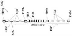
本说明书公开了一种吻合装置,包括:金属丝,其中所述金属丝具有第一状态和第二状态,其中在所述第一状态下,所述金属丝具有基本线性的形式,其中在所述第二状态下,所述金属丝形成具有至少第一环和第二环的线圈,并且其中当暴露于大于阈值的温度时,所述金属丝适于从所述第一状态转变到所述第二状态,并且其中所述第一环通过桥接段连接到所述第二环,所述桥接段包括预定长度的所述金属丝,使得所述金属丝在从所述第一状态改变到所述第二状态时能够在第一方向上盘绕到所述第一环中,并且在第二相反方向上盘绕到所述第二环中;多个磁体,定位在所述第一环和所述第二环上,其中所述多个磁体中的每一个都具有所述金属丝延伸穿过的内腔,其中在所述第一环和第二环中的每一个中,所述多个磁体的相邻磁体的一部分被配置为不相互连接,并且其中所述第一环中的所述多个磁体的一部分被配置为吸引所述第二环中的所述多个磁体的一部分;以及支架,定位在所述桥接段上,其中所述支架可从第一收缩状态膨胀到第二膨胀状态,其中所述支架具有所述桥接段延伸穿过的内腔。The present specification discloses an anastomotic device comprising: a wire, wherein the wire has a first state and a second state, wherein in the first state the wire has a substantially linear form, wherein in the In the second state, the wire forms a coil having at least a first loop and a second loop, and wherein the wire is adapted to transition from the first state to the a second state, and wherein the first loop is connected to the second loop by a bridge segment comprising a predetermined length of the wire such that the wire changes from the first state to the second state the second state is capable of being coiled into the first ring in a first direction and coiled into the second ring in a second opposite direction; a plurality of magnets positioned on the first ring and the second ring On a second ring, wherein each of the plurality of magnets has a lumen through which the wire extends, wherein in each of the first and second rings, the plurality of magnets A portion of adjacent magnets are configured not to connect to each other, and wherein a portion of the plurality of magnets in the first ring is configured to attract a portion of the plurality of magnets in the second ring; and a bracket , positioned on the bridging segment, wherein the stent is expandable from a first collapsed state to a second expanded state, wherein the stent has a lumen through which the bridging segment extends.
可选地,所述支架位于其上的所述桥接段不是盘绕状的。Optionally, the bridging segment on which the bracket rests is not coiled.
可选地,所述金属丝的尖端与由陶瓷材料制成的烧灼尖端耦接,用于刺穿身体组织。Optionally, the tip of the wire is coupled to a cautery tip made of ceramic material for piercing body tissue.
可选地,在所述第二状态下,所述金属丝形成具有至少四个线圈环的线圈。Optionally, in the second state, the wire forms a coil having at least four coil loops.
可选地,在通过导管将所述装置定位在体腔内之前,将所述吻合装置包装在形状设定模具中,所述形状设定模具使所述装置保持在所述第二状态,其中所述金属丝形成具有第一近端和第二远端的线圈,所述第一近端包括用于与所述导管耦接的螺纹连接器,所述第二远端具有用于刺穿所述相邻的身体组织的所述尖端,并且其中所述近端和所述远端朝向所述线圈环的中心弯曲15°至20°,以便在将所述装置定位在所述体腔内的过程中,使所述导管能够以至少30°的角度离开内窥镜提拉器。Optionally, prior to positioning the device within the body cavity through the catheter, the anastomotic device is packaged in a shape setting mold that maintains the device in the second state, wherein the The wire forms a coil having a first proximal end including a threaded connector for coupling with the catheter and a second distal end, the second distal end having a threaded connector for piercing the catheter the tip of adjacent body tissue, and wherein the proximal end and the distal end are bent 15° to 20° toward the center of the coil loop for positioning the device within the body cavity , enabling the catheter to exit the endoscope lifter at an angle of at least 30°.
可选地,通过将所述金属丝暴露于高于37摄氏度的温度,使所述金属丝从所述第一状态转变到所述第二状态。Optionally, the wire is transitioned from the first state to the second state by exposing the wire to a temperature above 37 degrees Celsius.
可选地,所述吻合装置用于在患者的胆囊和小肠之间形成吻合,以治疗糖尿病、肥胖症和代谢综合征之一。Optionally, the anastomotic device is used to form an anastomosis between a patient's gallbladder and small intestine to treat one of diabetes, obesity and metabolic syndrome.
可选地,所述吻合装置用于在患者的胆囊和小肠之间形成吻合,以治疗胆囊动力异常、胆囊运动障碍、胆源性运动障碍和胆源性胰腺炎中的一种。Optionally, the anastomotic device is used to form an anastomosis between the patient's gallbladder and small intestine to treat one of gallbladder motility abnormalities, gallbladder dyskinesias, biliary dyskinesias, and biliary pancreatitis.
可选地,当所述金属丝从所述第一状态改变到所述第二状态时,所述桥接段盘绕成“S”形。Optionally, when the wire changes from the first state to the second state, the bridging segment is coiled into an "S" shape.
可选地,所述第一环的未连接到所述桥接段的一端向内转向所述第一环的中心。Optionally, the end of the first ring that is not connected to the bridging segment is turned inwardly towards the center of the first ring.
可选地,所述第二环的未连接到所述桥接段的一端向内转向所述第二环的中心。Optionally, the end of the second ring that is not connected to the bridging segment is turned inwardly towards the center of the second ring.
可选地,所述吻合装置还包括位于所述多个磁体的相邻磁体之间的非铁磁间隔件。Optionally, the anastomotic device further includes a non-ferromagnetic spacer between adjacent ones of the plurality of magnets.
可选地,所述金属丝包括形状记忆合金。Optionally, the wire includes a shape memory alloy.
本说明书还公开了一种吻合装置,包括:包括第一部分和第二部分以及所述第一部分和所述第二部分之间的连接部分的金属丝;围绕所述金属丝的所述第一部分同轴定位的第一多个磁体;围绕所述金属丝的所述第二部分同轴定位的第二多个磁体;以及覆盖所述金属丝的所述连接部分的支架。The present specification also discloses an anastomotic device, comprising: a metal wire including a first part and a second part and a connecting part between the first part and the second part; the first part surrounding the metal wire has the same a first plurality of magnets positioned axially; a second plurality of magnets positioned coaxially about the second portion of the wire; and a bracket covering the connecting portion of the wire.
可选地,吻合装置还包括位于所述第一多个磁体和所述第二多个磁体的相邻磁体之间的非铁磁间隔件。Optionally, the anastomotic device further includes a non-ferromagnetic spacer between adjacent magnets of the first plurality of magnets and the second plurality of magnets.
可选地,所述金属丝包括形状记忆合金。Optionally, the wire includes a shape memory alloy.
可选地,所述金属丝的所述第一部分、第二部分和连接部分具有第一状态和第二状态,其中,在所述第一状态下,所述金属丝的第一部分、第二部分和连接部分具有基本线性的形式,并且其中,在所述第二状态下,所述金属丝的所述第一部分和所述第二部分形成盘绕的形状,并且所述金属丝的所述连接部分形成“S”形,并且其中所述金属丝的所述第一部分、第二部分和连接部分适于在暴露于大于阈值的温度时从所述第一状态转变到所述第二状态。可选地,通过将所述金属丝暴露于高于37摄氏度的温度,使所述金属丝的所述第一部分、第二部分和连接部分从所述第一状态转变到所述第二状态。Optionally, the first portion, the second portion and the connecting portion of the wire have a first state and a second state, wherein, in the first state, the first portion, the second portion of the wire and the connecting portion has a substantially linear form, and wherein, in the second state, the first portion and the second portion of the wire form a coiled shape, and the connecting portion of the wire An "S" shape is formed, and wherein the first, second and connecting portions of the wire are adapted to transition from the first state to the second state upon exposure to a temperature greater than a threshold. Optionally, the first portion, the second portion and the connecting portion of the wire are transitioned from the first state to the second state by exposing the wire to a temperature above 37 degrees Celsius.
可选地,所述支架可从第一收缩状态膨胀至第二膨胀状态。Optionally, the stent is expandable from a first collapsed state to a second expanded state.
可选地,所述支架具有所述连接构件延伸穿过的内腔。Optionally, the stent has a lumen through which the connecting member extends.
可选地,所述第一多个磁体和所述第二多个磁体被PTFE材料覆盖。Optionally, the first plurality of magnets and the second plurality of magnets are covered with PTFE material.
可选地,所述金属丝的尖端与由陶瓷材料制成的烧灼尖端耦接,用于刺穿身体组织。Optionally, the tip of the wire is coupled to a cautery tip made of ceramic material for piercing body tissue.
本说明书还公开了一种用于将吻合装置放置在器官内的预定位置的输送装置,所述输送装置包括:手柄,包括由外管同轴包围的内轴;以及主体,包括围绕所述内轴同轴定位的管状护套,所述内轴包括用于引导所述吻合装置的多个凹槽;其中在所述吻合装置通过所述管状护套放置在所述预定位置期间,所述内轴相对于所述外管旋转,并且其中在所述放置的至少一部分期间,所述凹槽使得所述内轴能够在所述外管内旋转。The present specification also discloses a delivery device for placing an anastomotic device at a predetermined position in an organ, the delivery device comprising: a handle including an inner shaft coaxially surrounded by an outer tube; and a body including surrounding the inner shaft a tubular sheath with a shaft coaxially positioned, the inner shaft including a plurality of grooves for guiding the anastomotic device; wherein during placement of the anastomotic device in the predetermined position through the tubular sheath, the inner shaft includes a plurality of grooves for guiding the anastomotic device; The shaft rotates relative to the outer tube, and wherein the groove enables rotation of the inner shaft within the outer tube during at least a portion of the placement.
本说明书还公开了一种在两个相邻的身体组织之间形成吻合和嵌入支架的方法,包括:通过导管将吻合装置定位在体腔内,所述体腔靠近至少一个所述相邻的身体组织,其中所述吻合装置包括:金属丝,其中所述金属丝具有第一状态和第二状态,其中在所述第一状态下,所述金属丝具有基本线性的形式,其中在所述第二状态下,所述金属丝形成具有至少第一环和第二环的线圈,并且其中当暴露于大于阈值的温度时,所述金属丝适于从所述第一状态转变到所述第二状态;多个磁体,定位在所述金属丝的第一部分上,其中所述多个磁体中的每一个都具有所述金属丝延伸穿过的内腔,其中在所述第一环和第二环中的每一个中,所述多个磁体的相邻磁体的一部分被配置为不相互连接,并且其中所述第一环中的所述多个磁体的一部分被配置为吸引所述第二环中的所述多个磁体的一部分;以及支架,定位在所述金属丝的第二部分上,其中所述支架可从第一收缩状态膨胀到第二膨胀状态,其中所述支架具有所述金属丝延伸穿过的内腔,并且其中所述金属丝的所述第二部分不包括所述多个磁体中的任何一个;刺穿所述相邻的身体组织,并通过所述刺穿产生的孔定位所述吻合装置;释放所述吻合装置,使得当其从所述第一状态转变到所述第二状态时,两个所述相邻的身体组织之间的组织被夹在所述第一环和所述第二环之间,从而被压缩并导致吻合,并且所述支架位于所述相邻的身体组织之间。The present specification also discloses a method of forming an anastomosis and embedding a stent between two adjacent body tissues, comprising: positioning an anastomotic device through a catheter within a body cavity, the body cavity being proximate to at least one of the adjacent body tissues , wherein the anastomotic device comprises: a wire, wherein the wire has a first state and a second state, wherein in the first state the wire has a substantially linear form, wherein in the second state state, the wire forms a coil having at least a first loop and a second loop, and wherein the wire is adapted to transition from the first state to the second state when exposed to a temperature greater than a threshold a plurality of magnets positioned on the first portion of the wire, wherein each of the plurality of magnets has a lumen through which the wire extends, wherein the first ring and the second ring In each of the plurality of magnets, a portion of adjacent magnets of the plurality of magnets are configured not to connect to each other, and wherein a portion of the plurality of magnets in the first ring is configured to attract the second ring of magnets. a portion of the plurality of magnets; and a stent positioned on the second portion of the wire, wherein the stent is expandable from a first contracted state to a second expanded state, wherein the stent has the wire a lumen extending therethrough, and wherein the second portion of the wire does not include any of the plurality of magnets; piercing the adjacent body tissue and passing through the hole created by the piercing positioning the anastomotic device; releasing the anastomotic device such that when it transitions from the first state to the second state, tissue between two of the adjacent bodily tissues is clamped in the first between the ring and the second ring, thereby being compressed and causing an anastomosis, and the stent is positioned between the adjacent body tissue.
可选地,所述吻合装置还包括位于所述多个磁体的相邻磁体之间的非铁磁间隔件。可选地,每个所述非铁磁间隔件的长度足以保持所述相邻磁体的相对磁极之间的吸引力低于所述线圈的弯曲力。Optionally, the anastomotic device further includes a non-ferromagnetic spacer between adjacent ones of the plurality of magnets. Optionally, each of the non-ferromagnetic spacers is of sufficient length to keep the attractive force between opposing poles of the adjacent magnets below the bending force of the coil.
可选地,当处于所述第二状态时,所述第一环和所述第二环的最大横截面直径在5mm至50mm的范围内。Optionally, the maximum cross-sectional diameter of the first ring and the second ring is in the range of 5mm to 50mm when in the second state.
可选地,所述多个磁体中的每一个具有0.2mm至7mm范围内的最大横截面长度或直径以及0.01lb至4lb范围内的拉力。Optionally, each of the plurality of magnets has a maximum cross-sectional length or diameter in the range of 0.2 mm to 7 mm and a tensile force in the range of 0.01 lb to 4 lb.
可选地,在所述第一环和所述第二环中,所述多个磁体的至少50%的所述相邻磁体被布置成相同磁极相对,从而在所述线圈的所述第一环中的所述相邻磁体之间产生排斥力,并且在所述第二环中的所述相邻磁体之间产生排斥力。Optionally, in the first ring and the second ring, at least 50% of the adjacent magnets of the plurality of magnets are arranged with the same magnetic pole opposite, so that in the first ring of the coil Repulsive forces are created between the adjacent magnets in the ring, and repulsive forces are created between the adjacent magnets in the second ring.
可选地,所述金属丝的至少一端连接到输送装置。Optionally, at least one end of the wire is connected to a delivery device.
可选地,所述金属丝包括形状记忆合金。Optionally, the wire includes a shape memory alloy.
可选地,所述阈值是20摄氏度。Optionally, the threshold is 20 degrees Celsius.
可选地,所述线圈具有靠近所述第一环的至少一个环和远离所述第二环的至少一个环。Optionally, the coil has at least one loop proximate the first loop and at least one loop remote from the second loop.
可选地,所述多个磁体中的每一个是圆柱形的,并且是覆盖有金、镍、特氟隆、聚对二甲苯、铜、锌、硅树脂、环氧树脂和钛中的至少一种的稀土磁体。Optionally, each of the plurality of magnets is cylindrical and is coated with at least one of gold, nickel, Teflon, parylene, copper, zinc, silicone, epoxy and titanium A rare earth magnet.
可选地,权利要求1所述的方法还包括,在释放所述吻合装置之前,通过使电流流过所述吻合装置来使所述吻合装置受热,以帮助从所述第一状态到所述第二状态的所述转变。Optionally, the method of
可选地,所述金属丝的直径在0.1mm至10mm之间,长度在1cm至250cm之间。Optionally, the diameter of the metal wire is between 0.1 mm and 10 mm, and the length is between 1 cm and 250 cm.
可选地,所述金属丝的直径在0.1mm和6mm之间,并且在所述第一状态下具有小于10%的最大应变,并且其中所述第一环和所述第二环的最大横截面尺寸在所述第二状态下在5mm至60mm的范围内。Optionally, the wire has a diameter of between 0.1 mm and 6 mm and has a maximum strain of less than 10% in the first state, and wherein the first loop and the second loop have a maximum transverse The cross-sectional dimension is in the range of 5 mm to 60 mm in the second state.
可选地,所述相邻的身体组织包括胆囊和十二指肠,并且所述第一环和所述第二环的最大直径小于或等于30mm。Optionally, the adjacent body tissue includes the gallbladder and the duodenum, and the first and second rings have a maximum diameter of less than or equal to 30 mm.
可选地,所述相邻的身体组织包括胰腺组织,并且所述第一环和所述第二环的最大直径大于或等于5mm。Optionally, the adjacent body tissue includes pancreatic tissue, and the first and second rings have a maximum diameter greater than or equal to 5 mm.
可选地,所述相邻的身体组织包括胆管组织,并且所述第一环和所述第二环的最大直径大于或等于5mm。Optionally, the adjacent body tissue includes bile duct tissue, and the first and second rings have a maximum diameter greater than or equal to 5 mm.
可选地,所述金属丝的直径小于0.5mm,并且其中所述第一环和所述第二环的最大横截面尺寸小于或等于15mm。Optionally, the diameter of the wire is less than 0.5 mm, and wherein the largest cross-sectional dimension of the first loop and the second loop is less than or equal to 15 mm.
可选地,所述金属丝的直径在0.5mm至1.0mm的范围内,并且其中所述第一环和所述第二环的最大横截面尺寸在10mm至45mm的范围内。Optionally, the diameter of the wire is in the range of 0.5mm to 1.0mm, and wherein the largest cross-sectional dimension of the first and second loops is in the range of 10mm to 45mm.
可选地,所述金属丝的直径大于1mm,并且其中所述第一环和所述第二环的最大横截面尺寸大于20mm。Optionally, the diameter of the wire is greater than 1 mm, and wherein the largest cross-sectional dimension of the first loop and the second loop is greater than 20 mm.
可选地,所述第一环所述和第二环具有圆形、多边形和具有四个或更多个点的星形中的至少一个。Optionally, the first and second rings have at least one of a circle, a polygon, and a star with four or more points.
可选地,在同一环上的所述多个磁体的所述相邻磁体的一部分被配置为相互排斥。Optionally, a portion of the adjacent magnets of the plurality of magnets on the same ring are configured to repel each other.
可选地,所述支架包括由第一半径限定的中间部分和由第二半径限定的端部,并且其中所述第二半径大于所述第一半径。Optionally, the stent includes an intermediate portion defined by a first radius and an end portion defined by a second radius, and wherein the second radius is greater than the first radius.
可选地,所述支架包括由生物相容性材料覆盖的金属丝网。Optionally, the stent comprises a wire mesh covered with a biocompatible material.
可选地,所述支架通过缝合法、压接法、胶合法或焊接法固定到金属丝上。Optionally, the stent is fixed to the wire by suturing, crimping, gluing or welding.
可选地,所述支架是由长度和半径限定的圆柱体,其中所述半径在所述长度的一部分上是恒定的。Optionally, the stent is a cylinder defined by a length and a radius, wherein the radius is constant over a portion of the length.
可选地,所述支架是由长度和半径限定的圆柱体,其中所述半径在所述长度的一部分上不恒定。Optionally, the stent is a cylinder defined by a length and a radius, wherein the radius is not constant over a portion of the length.
将在下面提供的附图和具体实施方式中更深入地描述本发明的前述和其他实施例。The foregoing and other embodiments of the present invention will be described in greater detail in the accompanying drawings and detailed description provided below.
附图说明Description of drawings
当结合附图考虑时,通过参考具体实施方式,将更好地理解本发明的这些和其他特征和优点:These and other features and advantages of the present invention will be better understood by reference to the detailed description when considered in conjunction with the accompanying drawings:
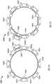
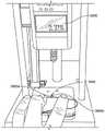
图1示出了根据本说明书的一个实施例的在人体内盘绕的直的形状记忆合金(SMA)金属丝;Figure 1 illustrates a straight shape memory alloy (SMA) wire coiled in a human body according to one embodiment of the present specification;
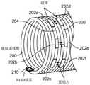
图2示出了根据本说明书的一个实施例的穿过SMA金属丝的环的多个磁体;Figure 2 illustrates a plurality of magnets passing through a loop of SMA wire according to one embodiment of the present specification;
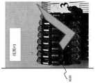
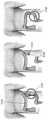
图3A示出了根据本说明书的一个实施例,使用内窥镜刺穿有胆结石的胆囊以放置SMA金属丝,从而形成吻合;Figure 3A illustrates the use of an endoscope to pierce a gallbladder with gallstones to place an SMA wire to form an anastomosis, according to one embodiment of the present specification;
图3B示出了根据本说明书的一个实施例,SMA线圈在图3A所示的胆囊和十二指肠之间形成吻合;Figure 3B shows an SMA coil forming an anastomosis between the gallbladder and duodenum shown in Figure 3A, according to one embodiment of the present specification;
图3C示出了根据本说明书的另一实施例,穿有磁体的SMA线圈在胆囊和十二指肠之间形成吻合;Figure 3C shows an SMA coil pierced with a magnet to form an anastomosis between the gallbladder and the duodenum according to another embodiment of the present specification;
图3D是根据本说明书的一个实施例的图3C所示的穿有磁体的SMA线圈的近视图;3D is a close-up view of the SMA coil shown in FIG. 3C threaded with a magnet, according to one embodiment of the present specification;
图4A示出了根据本说明书的一个实施例的吻合过程的第一阶段;Figure 4A shows the first stage of an anastomosis process according to one embodiment of the present specification;
图4B示出了根据本说明书的一个实施例的图4A所示的吻合过程的第二阶段;Figure 4B illustrates the second stage of the anastomosis process shown in Figure 4A, according to one embodiment of the present specification;
图4C示出了根据本说明书的一个实施例的图4A和图4B所示的吻合过程的第三阶段;Figure 4C shows the third stage of the anastomosis process shown in Figures 4A and 4B according to one embodiment of the present specification;
图4D示出了根据本说明书的一个实施例,作为图4A、图4B和图4C所示的吻合过程的第四阶段,也是最终阶段的吻合的形成;Figure 4D illustrates the formation of an anastomosis as the fourth and final stage of the anastomosis process shown in Figures 4A, 4B and 4C, according to one embodiment of the present specification;
图5示出了根据本说明书的实施例的表格,该表格示出了用于形成吻合的SMA金属丝的示例性尺寸;FIG. 5 shows a table showing exemplary dimensions of SMA wires for forming anastomosis according to an embodiment of the present specification;
图6示出了根据本说明书的一个实施例的与磁体耦接以形成吻合的方形SMA线圈;Figure 6 illustrates a square SMA coil coupled to a magnet to form a fit, according to one embodiment of the present specification;
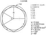
图7A示出了根据本说明书的一个实施例的与磁体耦接以形成吻合的六边形SMA线圈;Figure 7A illustrates a hexagonal SMA coil coupled with a magnet to form a snug fit, according to one embodiment of the present specification;
图7B示出了根据本说明书的一个实施例的图7A所示的六边形SMA线圈的示例性尺寸;Figure 7B illustrates exemplary dimensions of the hexagonal SMA coil shown in Figure 7A according to one embodiment of the present specification;
图7C示出了根据本说明书的一个实施例的与磁体耦接以形成吻合的第一十边形SMA线圈;Figure 7C illustrates a first decagonal SMA coil coupled with a magnet to form a fit, according to one embodiment of the present specification;
图7D示出了根据本说明书的另一实施例的与磁体耦接以形成吻合的第二十边形SMA线圈;Figure 7D illustrates a twentieth decagon SMA coil coupled with a magnet to form a fit, according to another embodiment of the present specification;
图7E示出了根据本说明书的一个实施例的与磁体耦接以形成吻合的十边形SMA线圈的示例性尺寸;Figure 7E illustrates exemplary dimensions of a decagonal SMA coil coupled with a magnet to form a snug fit, according to one embodiment of the present specification;
图7F示出了根据本说明书的一个实施例的与磁体耦接以形成吻合的十二边形SMA线圈;Figure 7F illustrates a dodecagonal SMA coil coupled with a magnet to form a fit, according to one embodiment of the present specification;
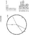
图7G示出了根据本说明书的一个实施例的六边形SMA线圈的示例性尺寸;Figure 7G illustrates exemplary dimensions of a hexagonal SMA coil according to one embodiment of the present specification;
图7H示出了根据本说明书的一个实施例的八边形SMA线圈的示例性尺寸;Figure 7H illustrates exemplary dimensions of an octagonal SMA coil according to one embodiment of the present specification;
图7I示出了根据本说明书的一个实施例的十边形SMA线圈的示例性尺寸;Figure 7I illustrates exemplary dimensions of a decagonal SMA coil according to one embodiment of the present specification;
图7J示出了根据本说明书的一个实施例的十二边形SMA线圈的示例性尺寸;Figure 7J illustrates exemplary dimensions of a dodecagonal SMA coil according to one embodiment of the present specification;
图7K示出了根据本说明书的一个实施例的十四边形SMA线圈的示例性尺寸;Figure 7K shows exemplary dimensions of a tetradecagonal SMA coil according to one embodiment of the present specification;
图8示出了根据本说明书的一个实施例,通过使用SMA线圈形成吻合的过程;Figure 8 illustrates the process of forming an anastomosis by using an SMA coil according to one embodiment of the present specification;
图9A示出了根据本说明书的一个实施例的被压缩在SMA线圈的环之间的两个器官的壁;Figure 9A shows the walls of two organs compressed between loops of SMA coils according to one embodiment of the present specification;
图9B示出了根据本说明书的一个实施例的被压缩在SMA线圈的环之间的两个器官的壁,通过使用磁体而使压缩力增强;Figure 9B shows the walls of two organs compressed between loops of SMA coils, the compression force being enhanced by the use of magnets, according to one embodiment of the present specification;
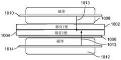
图10示出了根据本说明书的一个实施例的被压缩在SMA线圈的环和磁体之间的两个器官的壁;Figure 10 shows the walls of two organs compressed between a loop of an SMA coil and a magnet, according to one embodiment of the present specification;
图11示出了根据本说明书的一个实施例的与SMA线圈的环耦接以形成吻合的多个磁体;Figure 11 illustrates a plurality of magnets coupled to a loop of SMA coil to form a fit, according to one embodiment of the present specification;
图12示出了根据本说明书的另一实施例的与SMA线圈的环耦接以形成吻合的多个磁体;Figure 12 illustrates a plurality of magnets coupled to a loop of SMA coils to form a fit in accordance with another embodiment of the present specification;
图13示出了根据本说明书的一个实施例,与SMA线圈的相邻环耦接以形成吻合的磁体的放置;FIG. 13 illustrates placement of magnets coupled with adjacent loops of SMA coils to form coherent magnets, according to one embodiment of the present specification;
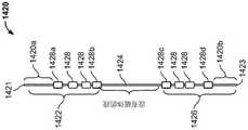
图14A示出了根据本说明书的一个实施例的在放置在体内之前与磁体耦接以形成吻合的示例性SMA金属丝;14A illustrates an exemplary SMA wire coupled to a magnet to form an anastomosis prior to placement in the body according to one embodiment of the present specification;
图14B示出了根据本说明书的一个实施例的在中间放置阶段与图14A所示的磁体耦接的示例性SMA金属丝;14B illustrates an exemplary SMA wire coupled to the magnet shown in FIG. 14A at an intermediate placement stage, according to one embodiment of the present specification;
图14C示出了根据本说明书的一个实施例的在放置在体内后与图14A所示的磁体耦接以形成吻合的示例性SMA金属丝;Figure 14C illustrates an exemplary SMA wire coupled to the magnet shown in Figure 14A to form an anastomosis after placement in the body, according to one embodiment of the present specification;
图14D示出了根据本说明书的另一实施例的在放置在体内前与磁体耦接以形成吻合的示例性SMA金属丝;14D illustrates an exemplary SMA wire coupled to a magnet to form an anastomosis prior to placement in the body according to another embodiment of the present specification;
图14E示出了根据本说明书的一个实施例的在中间放置阶段与图14D所示的磁体耦接的示例性SMA金属丝;Figure 14E shows an exemplary SMA wire coupled to the magnet shown in Figure 14D at an intermediate placement stage, according to one embodiment of the present specification;
图14F示出了根据本说明书的一个实施例的在放置在体内后与图14D所示的磁体耦接以形成吻合的示例性SMA金属丝;Figure 14F illustrates an exemplary SMA wire coupled to the magnet shown in Figure 14D to form an anastomosis after placement in the body, according to one embodiment of the present specification;
图15A示出了根据本说明书的另一实施例的在放置在体内之前与磁体耦接以形成吻合的示例性SMA金属丝;15A illustrates an exemplary SMA wire coupled to a magnet to form an anastomosis prior to placement in the body according to another embodiment of the present specification;
图15B示出了根据本说明书的一个实施例的在中间放置阶段与图15A所示的磁体耦接的示例性SMA金属丝;Figure 15B illustrates an exemplary SMA wire coupled to the magnet shown in Figure 15A at an intermediate placement stage, according to one embodiment of the present specification;
图15C示出了根据本说明书的一个实施例的在放置在体内后与图15A所示的磁体耦接以形成吻合的示例性SMA金属丝;Figure 15C shows an exemplary SMA wire coupled to the magnet shown in Figure 15A to form an anastomosis after placement in the body, according to one embodiment of the present specification;
图15D示出了根据本说明书的又一实施例的在放置在体内之前与磁体耦接以形成吻合的示例性SMA金属丝;15D illustrates an exemplary SMA wire coupled to a magnet to form an anastomosis prior to placement in the body according to yet another embodiment of the present specification;
图15E示出了根据本说明书的一个实施例的在中间放置阶段与图15D所示的磁体耦接的示例性SMA金属丝;Figure 15E shows an exemplary SMA wire coupled to the magnet shown in Figure 15D at an intermediate placement stage, according to one embodiment of the present specification;
图15F示出了根据本说明书的一个实施例的在放置在体内后与图15D所示的磁体耦接以形成吻合的示例性SMA金属丝;Figure 15F shows an exemplary SMA wire coupled to the magnet shown in Figure 15D to form an anastomosis after placement in the body, according to one embodiment of the present specification;
图15G是示出根据本说明书的一个实施例,随着线圈上的磁体之间的距离减小,线圈的环施加在身体组织上的压力的曲线图;15G is a graph showing the pressure exerted by a loop of a coil on body tissue as the distance between the magnets on the coil decreases, according to one embodiment of the present specification;
图16A示出了根据本说明书的一个实施例的用于形成吻合的示例性圆形SMA线圈;Figure 16A illustrates an exemplary circular SMA coil for forming anastomosis according to one embodiment of the present specification;
图16B示出了根据本说明书的一个实施例的示例性圆形SMA线圈,其具有用于形成吻合的切割刃;Figure 16B illustrates an exemplary circular SMA coil having a cutting edge for forming an anastomosis according to one embodiment of the present specification;
图16C示出了根据本说明书的一个实施例的用于形成吻合的示例性方形SMA线圈;Figure 16C illustrates an exemplary square SMA coil for forming anastomosis according to one embodiment of the present specification;
图17A示出了根据本说明书的一个实施例的示例性装置,该装置包括与用于形成吻合的SMA线圈耦接的圆形磁体;FIG. 17A illustrates an exemplary device including a circular magnet coupled to an SMA coil for forming an anastomosis, according to one embodiment of the present specification;
图17B示出了根据本说明书的一个实施例的示例性装置,该装置包括与用于形成吻合的SMA线圈耦接的圆形磁体,其中至少一个磁体包括切割刃;17B illustrates an exemplary device including a circular magnet coupled with an SMA coil for forming a fit, wherein at least one magnet includes a cutting edge, according to one embodiment of the present specification;
图17C示出了根据本说明书的一个实施例的示例性装置,该装置包括与具有用于形成吻合的锯齿状边缘的SMA线圈耦接的方形磁体;17C illustrates an exemplary device including a square magnet coupled with an SMA coil having serrated edges for forming a fit, according to one embodiment of the present specification;
图17D示出了根据本说明书的另一实施例的示例性装置,该装置包括与用于形成吻合的SMA线圈耦接的方形磁体;17D illustrates an exemplary device including a square magnet coupled with an SMA coil for forming a fit, according to another embodiment of the present specification;
图17E示出了根据本说明书的一个实施例的示例性装置,该装置包括与用于形成吻合的SMA线圈耦接的方形磁体,其中至少一个磁体包括切割刃;17E illustrates an exemplary device including a square magnet coupled with an SMA coil for forming a fit, wherein at least one magnet includes a cutting edge, according to one embodiment of the present specification;
图17F示出了根据本说明书的一个实施例的示例性装置的横截面图,该装置包括与用于形成吻合的SMA线圈耦接的圆形磁体,其中磁体包括凸边以利于切割;17F shows a cross-sectional view of an exemplary device including a circular magnet coupled with an SMA coil for forming a fit, wherein the magnet includes a knurled edge to facilitate cutting, according to one embodiment of the present specification;
图17G示出了根据本说明书的一个实施例的示例性装置的横截面图,该装置包括与用于形成吻合的SMA线圈耦接的方形磁体,其中磁体包括凸边以利于切割;17G shows a cross-sectional view of an exemplary device including a square magnet coupled with an SMA coil for forming a fit, wherein the magnet includes a raised edge to facilitate cutting, according to one embodiment of the present specification;
图18A示出了根据本说明书的一个实施例的多个磁体的第一配置,这些磁体围绕用于形成吻合的SMA金属丝线圈的环布置;Figure 18A shows a first configuration of a plurality of magnets arranged around a loop for forming a stapled SMA wire coil, according to one embodiment of the present specification;
图18B示出了根据本说明书的另一实施例的多个磁体的第二配置,这些磁体围绕用于形成吻合的SMA金属丝线圈的环布置;Figure 18B shows a second configuration of a plurality of magnets arranged around a loop for forming an anastomotic SMA wire coil according to another embodiment of the present specification;
图18C示出了根据本说明书的一个实施例的多个磁体的第三配置,这些磁体围绕由非铁磁间隔件分开的用于形成吻合的SMA金属丝线圈的环布置;FIG. 18C shows a third configuration of a plurality of magnets arranged around a loop separated by non-ferromagnetic spacers for forming anastomotic SMA wire coils, according to one embodiment of the present specification;
图18D示出了根据本说明书的另一实施例的多个磁体的第四配置,这些磁体围绕由非铁磁间隔件分开的用于形成吻合的SMA金属丝线圈的环布置;Figure 18D shows a fourth configuration of a plurality of magnets arranged around a loop of SMA wire separated by non-ferromagnetic spacers for forming anastomotic SMA wire coils according to another embodiment of the present specification;
图18E示出了根据本说明书的一个实施例的围绕用于形成吻合的SMA线圈的环的磁体的第五配置;18E illustrates a fifth configuration of magnets surrounding a loop for forming an anastomotic SMA coil according to one embodiment of the present specification;
图18F示出了根据本说明书的一个实施例的围绕用于形成吻合的SMA线圈的环的磁体的第六配置;Figure 18F illustrates a sixth configuration of magnets surrounding a loop for forming an anastomotic SMA coil according to one embodiment of the present specification;
图19A示出了根据本说明书的一个实施例,在人体内的两个器官之间形成吻合的第一步骤;Figure 19A shows the first step of forming an anastomosis between two organs in a human body according to one embodiment of the present specification;
图19B示出了根据本说明书的一个实施例,在人体内的两个器官之间形成吻合的第二步骤;Figure 19B illustrates the second step of forming an anastomosis between two organs in the human body according to one embodiment of the present specification;
图19C示出了根据本说明书的一个实施例,在人体内的两个器官之间形成吻合的第三步骤;Figure 19C shows a third step in forming an anastomosis between two organs in a human body according to one embodiment of the present specification;
图20A示出了根据本说明书的一个实施例的用于在体内输送SMA线圈的非烧灼针;Figure 20A illustrates a non-cautery needle for in vivo delivery of SMA coils according to one embodiment of the present specification;
图20B示出了根据本说明书的一个实施例的图20A所示的非烧灼针的手柄;Figure 20B shows the handle of the non-cautery needle shown in Figure 20A according to one embodiment of the present specification;
图21示出了根据本说明书的一个实施例的烧灼针装置,该烧灼针装置用于经由内窥镜在体内输送SMA线圈;Figure 21 illustrates a cautery needle device for delivering an SMA coil in vivo via an endoscope, according to one embodiment of the present specification;
图22示出了根据本说明书的一个实施例的烧灼针装置,该烧灼针装置用于在导丝的帮助下经由内窥镜在体内输送SMA线圈;Figure 22 illustrates a cautery needle device for delivering an SMA coil in vivo via an endoscope with the aid of a guide wire, according to one embodiment of the present specification;
图23A示出了根据本说明书的一个实施例的将SMA线圈从输送导管释放的机构;Figure 23A illustrates a mechanism for releasing an SMA coil from a delivery catheter according to one embodiment of the present specification;
图23B示出了根据本说明书的一个实施例,从图23A所示的输送导管释放SMA线圈;Figure 23B illustrates the release of an SMA coil from the delivery catheter shown in Figure 23A, according to one embodiment of the present specification;
图24A示出了根据本说明书的另一实施例的将SMA线圈从输送导管释放的机构;24A illustrates a mechanism for releasing an SMA coil from a delivery catheter according to another embodiment of the present specification;
图24B示出了根据本说明书的一个实施例,从图24A所示的输送导管释放SMA线圈;Figure 24B illustrates the release of an SMA coil from the delivery catheter shown in Figure 24A, according to one embodiment of the present specification;
图25是示出根据本说明书的一个实施例的通过使用吻合器械形成吻合的步骤的流程图;Figure 25 is a flow chart illustrating the steps of forming an anastomosis by using an anastomotic instrument according to one embodiment of the present specification;
图26A示出了根据本说明书的一个实施例的盘绕前构型的用于形成吻合的示例性装置的第一视图;26A shows a first view of an exemplary device for forming anastomosis in a pre-coiled configuration according to one embodiment of the present specification;
图26B示出了盘绕前构型的图26A的用于形成吻合的装置的第二视图;Figure 26B shows a second view of the device for forming an anastomosis of Figure 26A in a pre-coiled configuration;
图26C示出了盘绕前构型的图26A的用于形成吻合的装置的第三视图;Figure 26C shows a third view of the device for forming an anastomosis of Figure 26A in a pre-coiled configuration;
图26D示出了盘绕构型的图26A的用于形成吻合的装置的侧视图;Figure 26D shows a side view of the device for forming an anastomosis of Figure 26A in a coiled configuration;
图26E示出了盘绕构型的图26A的用于形成吻合的装置的轴向视图;Figure 26E shows an axial view of the device for forming an anastomosis of Figure 26A in a coiled configuration;
图26F示出了根据本说明书的一个实施例的放置后锥形线圈构型的用于形成吻合的第一示例性装置;26F illustrates a first exemplary device for forming anastomosis in a post-placement conical coil configuration according to one embodiment of the present specification;
图26G示出了根据本说明书的一个实施例的放置后锥形线圈构型的用于形成吻合的第二示例性装置;Figure 26G illustrates a second exemplary device for forming anastomosis in a tapered coil configuration after placement according to one embodiment of the present specification;
图26H示出了放置后线圈构型的用于形成吻合的装置的实施例,该装置包括附接到线圈一端的单个凸缘;Figure 26H shows an embodiment of a device for forming anastomosis in a coil configuration after placement, the device comprising a single flange attached to one end of the coil;
图26I示出了放置后线圈构型的用于形成吻合的装置的另一实施例,该装置包括附接到线圈一端的单个凸缘;Figure 26I shows another embodiment of the device for forming an anastomosis in the coil configuration after placement, the device comprising a single flange attached to one end of the coil;
图26J示出了图26I的用于形成吻合的装置的侧视图;Figure 26J shows a side view of the device for forming an anastomosis of Figure 26I;
图26K示出了放置后线圈构型的用于形成吻合的装置的实施例,该装置包括附接到线圈各端的凸缘;Figure 26K shows an embodiment of a device for forming an anastomosis in a coil configuration after placement, the device including flanges attached to each end of the coil;
图26L示出了放置后线圈构型的用于形成吻合的装置的另一实施例,该装置包括附接到线圈各端的凸缘;Figure 26L shows another embodiment of the device for forming an anastomosis in the coil configuration after placement, the device including flanges attached to each end of the coil;
图26M示出了图26L的用于形成吻合的装置的附加视图;Figure 26M shows an additional view of the device for forming an anastomosis of Figure 26L;
图26N示出了图26L的用于形成吻合的装置的侧视图;Figure 26N shows a side view of the device for forming an anastomosis of Figure 26L;
图26O示出了用于制造图26L的具有凸缘的吻合装置的模具;Figure 26O shows a mold for making the flanged anastomotic device of Figure 26L;
图27示出了根据本说明书的一个实施例的放置前构型的具有输送导管的用于形成吻合的SMA线圈装置;27 illustrates an SMA coil device for forming anastomosis with a delivery catheter in a pre-placement configuration according to one embodiment of the present specification;
图28示出了根据本说明书的另一实施例的放置前构型的具有输送导管的用于形成吻合的SMA线圈装置;28 illustrates an SMA coil device for forming anastomosis with a delivery catheter in a pre-placement configuration according to another embodiment of the present specification;
图29A示出了根据本说明书的各种实施例的用于与吻合线圈装置一起放置的烧灼尖端;Figure 29A illustrates a cautery tip for placement with an anastomotic coil device in accordance with various embodiments of the present specification;
图29B示出了根据本说明书的一个实施例的放置前构型的设有烧灼尖端的吻合线圈装置;Figure 29B shows an anastomotic coil device with a cautery tip in a pre-placement configuration according to one embodiment of the present specification;
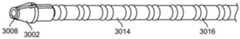
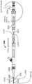
图30A示出了根据本说明书的一个实施例的放置前构型的具有远端烧灼尖端的吻合线圈装置的侧截面图;30A shows a side cross-sectional view of an anastomotic coil device with a distal cautery tip in a pre-placement configuration according to one embodiment of the present specification;
图30B示出了图30A中标记为3030的部分的放大视图;Figure 30B shows an enlarged view of the portion labeled 3030 in Figure 30A;
图30C示出了图30A中标记为3040的部分的放大视图;Figure 30C shows an enlarged view of the portion labeled 3040 in Figure 30A;
图30D示出了图30A所示的具有烧灼尖端的能够烧灼的吻合线圈装置的另一视图;Figure 30D shows another view of the cautery-capable anastomotic coil device with a cautery tip shown in Figure 30A;
图30E示出了图30A所示的吻合线圈装置的近端止动件和推进导管的耦接机构的放大视图;Figure 30E shows an enlarged view of the coupling mechanism of the proximal stop and the advancement catheter of the anastomotic coil device shown in Figure 30A;
图30F示出了与图30A所示的吻合线圈装置的烧灼电极耦接的烧灼尖端的近视图;Figure 30F shows a close-up view of the cautery tip coupled to the cautery electrode of the anastomotic coil device shown in Figure 30A;
图30G示出了图30F所示的烧灼尖端的前视图;Figure 30G shows a front view of the cautery tip shown in Figure 30F;
图30H示出了图30F所示的烧灼尖端和烧灼电极的侧截面图;Figure 30H shows a side cross-sectional view of the cautery tip and cautery electrode shown in Figure 30F;
图30I示出了图30F所示的烧灼电极;Figure 30I shows the cautery electrode shown in Figure 30F;
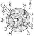
图31A示出了根据本说明书的一个实施例的用于输送吻合线圈装置的三腔导管的横截面图;31A shows a cross-sectional view of a triple lumen catheter for delivering an anastomotic coil device according to one embodiment of the present specification;
图31B示出了根据本说明书的一个实施例的放置前构型的吻合线圈装置和封装在导管中用于输送吻合线圈装置的导丝的侧截面图;31B shows a side cross-sectional view of an anastomotic coil device in a pre-placement configuration and a guidewire packaged in a catheter for delivery of the anastomotic coil device, according to one embodiment of the present specification;
图31C示出了沿着图31B所示的CC轴的横截面图;Figure 31C shows a cross-sectional view along the CC axis shown in Figure 31B;
图31D示出了沿着图31B所示的BB轴的横截面图;Figure 31D shows a cross-sectional view along the BB axis shown in Figure 31B;
图31E示出了用于输送图31B所示的吻合线圈装置的导管和导丝的另一视图;Figure 31E shows another view of the catheter and guidewire used to deliver the anastomotic coil device shown in Figure 31B;
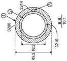
图32A示出了根据本说明书的另一实施例的设置在输送导管中的放置前构型的吻合线圈装置的横截面图;32A shows a cross-sectional view of an anastomotic coil device in a pre-placement configuration disposed in a delivery catheter according to another embodiment of the present specification;
图32B示出了沿着图32A所示的BB轴的横截面图;Figure 32B shows a cross-sectional view along the BB axis shown in Figure 32A;
图32C示出了沿着图32A所示的CC轴的横截面图;Figure 32C shows a cross-sectional view along the CC axis shown in Figure 32A;
图32D示出了沿着图32A所示的DD轴的横截面图;Figure 32D shows a cross-sectional view along the DD axis shown in Figure 32A;
图32E示出了图32A所示的导体头的放大视图;Figure 32E shows an enlarged view of the conductor tip shown in Figure 32A;
图32F示出了图32A所示的吻合线圈装置在体内输送后的放置后构型;Figure 32F shows the post-placement configuration of the anastomotic coil device shown in Figure 32A after in vivo delivery;
图32G示出了图32F所示的吻合线圈装置的横截面图;Figure 32G shows a cross-sectional view of the anastomotic coil device shown in Figure 32F;
图32H示出了用作如图32B所示的间隔件的O形环;Figure 32H shows an O-ring used as a spacer as shown in Figure 32B;
图33A示出了根据本说明书的一个实施例的用于输送设有烧灼尖端的吻合线圈装置的双手柄输送装置;33A illustrates a dual handle delivery device for delivering an anastomotic coil device with a cautery tip, according to one embodiment of the present specification;
图33B示出了图33A所示的第二手柄的放大视图;Figure 33B shows an enlarged view of the second handle shown in Figure 33A;
图34A示出了根据本说明书的一个实施例的用于输送设有烧灼尖端的吻合线圈装置的双手柄输送装置的截面图;34A shows a cross-sectional view of a dual handle delivery device for delivering an anastomotic coil device provided with a cautery tip, according to one embodiment of the present specification;
图34B示出了图34A所示的尖端部分的放大截面图;Figure 34B shows an enlarged cross-sectional view of the tip portion shown in Figure 34A;
图34C示出了图34B所示的尖端部分的横截面图;Figure 34C shows a cross-sectional view of the tip portion shown in Figure 34B;
图34D示出了图34A所示的导丝部分的放大截面图;Figure 34D shows an enlarged cross-sectional view of the guide wire portion shown in Figure 34A;
图34E示出了图34D所示的导丝部分的横截面图;Figure 34E shows a cross-sectional view of the guide wire portion shown in Figure 34D;
图34F示出了图34A所示的手柄部分的放大截面图;Figure 34F shows an enlarged cross-sectional view of the handle portion shown in Figure 34A;
图35是示出根据本说明书的一个实施例,通过使用形状记忆金属丝和相邻器官或结构之间的磁压缩力来形成吻合的步骤的流程图;Figure 35 is a flow chart illustrating the steps of forming an anastomosis by using a shape memory wire and magnetic compressive force between adjacent organs or structures, according to one embodiment of the present specification;
图36是示出根据本说明书的一个实施例,通过使用相邻器官之间具有磁体的形状记忆线圈来形成吻合的步骤的流程图;Figure 36 is a flow chart illustrating the steps of forming an anastomosis by using shape memory coils with magnets between adjacent organs according to one embodiment of the present specification;
图37是示出根据本说明书的一个实施例,通过使用形状记忆金属丝和相邻器官或结构之间的磁压缩力来形成吻合的步骤的流程图;Figure 37 is a flow chart illustrating the steps of forming an anastomosis by using a shape memory wire and magnetic compressive force between adjacent organs or structures, according to one embodiment of the present specification;
图38是示出根据本说明书的一个实施例,通过使用相邻器官之间具有磁体的形状记忆线圈来形成吻合的步骤的流程图;Figure 38 is a flow chart illustrating the steps of forming an anastomosis by using shape memory coils with magnets between adjacent organs in accordance with one embodiment of the present specification;
图39A示出了根据本说明书的一个实施例的与用于形成吻合的装置一起使用的示例性磁体;Figure 39A shows an exemplary magnet for use with a device for forming anastomosis according to one embodiment of the present specification;
图39B示出了根据本说明书的另一实施例的与用于形成吻合的装置一起使用的示例性磁体;Figure 39B illustrates an exemplary magnet for use with a device for forming anastomosis according to another embodiment of the present specification;
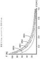
图39C是示出根据本说明书的一个实施例的压缩压力和由吻合装置提供的线圈环之间的距离之间的关系的曲线图,该吻合装置在将形成的吻合的每一侧上具有一个线圈环;Figure 39C is a graph showing the relationship between compression pressure and distance between coil loops provided by an anastomotic device having a coil loop;
图39D是示出根据本说明书的一个实施例的压缩压力和由吻合装置提供的线圈环之间的距离之间的关系的曲线图,该吻合装置在将形成的吻合的每一侧上具有两个线圈环;Figure 39D is a graph showing the relationship between compression pressure and distance between coil loops provided by an anastomotic device having two a coil loop;
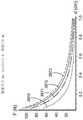
图39E是示出根据本说明书的一个实施例的压缩压力和由吻合装置提供的线圈环之间的距离之间的关系的曲线图,该吻合装置在将形成的吻合的每一侧上具有三个线圈环;Figure 39E is a graph showing the relationship between compression pressure and distance between coil loops provided by an anastomotic device having three a coil loop;
图39F是示出根据本说明书的一个实施例的压缩压力和由吻合装置提供的线圈环之间的距离之间的关系的曲线图,该吻合装置具有直径为2.0mm的磁体,并且在将形成的吻合的每一侧具有不同数量的线圈环;Figure 39F is a graph showing the relationship between compression pressure and distance between coil loops provided by an anastomotic device having a 2.0 mm diameter magnet and to be formed in accordance with one embodiment of the present specification Each side of the anastomosis has a different number of coil loops;
图39G是示出根据本说明书的一个实施例的力和由吻合装置提供的线圈环之间的距离之间的关系的曲线图,该吻合装置具有直径为2.0mm的磁体,并且在将形成的吻合的每一侧上具有不同数量的线圈环;Figure 39G is a graph showing the relationship between force and distance between coil loops provided by an anastomotic device having a 2.0 mm diameter magnet and in a to-be-formed, according to one embodiment of the present specification Different numbers of coil loops on each side of the anastomosis;
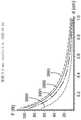
图39H是示出根据本说明书的一个实施例的压缩压力和由吻合装置提供的线圈环之间的距离之间的关系的曲线图,该吻合装置具有直径为2.5mm的磁体,并且在将形成的吻合的每一侧具有不同数量的线圈环;Figure 39H is a graph showing the relationship between compression pressure and distance between coil loops provided by an anastomotic device having a 2.5mm diameter magnet and to be formed in accordance with one embodiment of the present specification Each side of the anastomosis has a different number of coil loops;
图39I是示出根据本说明书的一个实施例的力和由吻合装置提供的线圈环之间的距离之间的关系的曲线图,该吻合装置具有直径为2.5mm的磁体,并且在将形成的吻合的每一侧具有不同数量的线圈环;Figure 39I is a graph showing the relationship between force and distance between coil loops provided by an anastomotic device having a 2.5 mm diameter magnet and in a to-be-formed according to one embodiment of the present specification Each side of the anastomosis has a different number of coil loops;
图39J是示出根据本说明书的一个实施例的压缩压力和由吻合装置提供的线圈环之间的距离之间的关系的曲线图,该吻合装置具有直径为3.0mm的磁体,并且在将形成的吻合的每一侧上具有不同数量的线圈环;Figure 39J is a graph showing the relationship between compression pressure and distance between coil loops provided by an anastomotic device having a 3.0 mm diameter magnet and to be formed in accordance with one embodiment of the present specification have different numbers of coil loops on each side of the anastomosis;
图39K是示出根据本说明书的一个实施例的力和由吻合装置提供的线圈环之间的距离之间的关系的曲线图,该吻合装置具有直径为3.0mm的磁体,并且在将形成的吻合的每一侧上具有不同数量的线圈环;Figure 39K is a graph showing the relationship between force and distance between coil loops provided by an anastomotic device having a 3.0 mm diameter magnet and in a to-be-formed according to one embodiment of the present specification Different numbers of coil loops on each side of the anastomosis;
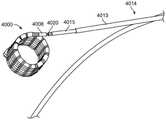
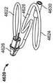
图40A示出了根据本说明书的一个实施例的盘绕前构型的用于形成吻合的示例性装置;Figure 40A illustrates an exemplary device for forming anastomosis in a pre-coiled configuration according to one embodiment of the present specification;
图40B示出了盘绕构型的图40A的用于形成吻合的装置;Figure 40B shows the device for forming an anastomosis of Figure 40A in a coiled configuration;
图40C示出了盘绕构型的图40A的用于形成吻合的装置的另一视图;Figure 40C shows another view of the device for forming an anastomosis of Figure 40A in a coiled configuration;
图40D示出了根据本说明书的一个实施例的用于将图40A、图40B和图40C所示的吻合装置输送到体内预定位置的输送装置;Figure 40D illustrates a delivery device for delivering the anastomotic device shown in Figures 40A, 40B and 40C to a predetermined location in the body according to one embodiment of the present specification;
图40E示出了根据本说明书的一个实施例的连接到图40B和图40C所示的盘绕吻合装置的图40D所示的输送装置;Figure 40E shows the delivery device shown in Figure 40D connected to the coiled anastomotic device shown in Figures 40B and 40C, according to one embodiment of the present specification;
图40F示出了根据本说明书的一个实施例的连接到图40B和图40C所示的盘绕吻合装置的图40D所示的输送装置的另一视图;Figure 40F shows another view of the delivery device shown in Figure 40D connected to the coiled anastomotic device shown in Figures 40B and 40C, according to one embodiment of the present specification;
图40G示出了根据本说明书的一个实施例的连接到图40B和图40C所示的盘绕吻合装置的图40D所示的输送装置的另一视图;Figure 40G shows another view of the delivery device shown in Figure 40D connected to the coiled anastomotic device shown in Figures 40B and 40C, according to one embodiment of the present specification;
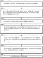
图40H是列出根据本说明书的一个实施例的使用输送装置放置吻合装置的方法中涉及的步骤的流程图。40H is a flowchart listing the steps involved in a method of placing an anastomotic device using a delivery device according to one embodiment of the present specification.
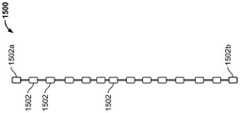
图41示出了根据本说明书的一个实施例的包括多个环状物的装置的视图;Figure 41 shows a view of a device including a plurality of rings according to one embodiment of the present specification;
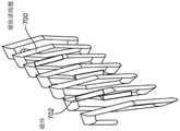
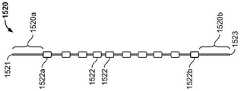
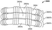
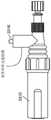
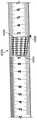
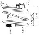
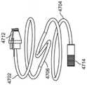
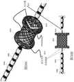
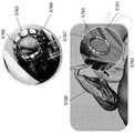
图42示出了根据本说明书的一个实施例的包括作为引流机构的可膨胀支架的装置的视图;Figure 42 shows a view of a device including an expandable stent as a drainage mechanism according to one embodiment of the present specification;
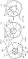
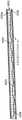
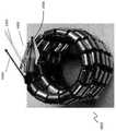
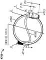
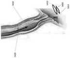
图43A示出了根据本说明书的一个实施例的盘绕装置的图像,该盘绕装置具有向内弯曲以防止边缘或端部过于尖锐的远端;Figure 43A shows an image of a coiled device having a distal end that is bent inward to prevent an edge or end from being too sharp, according to one embodiment of the present specification;
图43B示出了根据本说明书的一个实施例的远端向内弯曲的盘绕装置的按比例的侧视图;Figure 43B shows a scaled side view of a distal inwardly curved coil device according to one embodiment of the present specification;
图43C示出了根据本说明书的一个实施例的图43B的远端向内弯曲的盘绕装置的按比例的后视图;Figure 43C shows a scale rear view of the distally inwardly curved coil device of Figure 43B according to one embodiment of the present specification;
图43D示出了根据本说明书的一个可选实施例的图43B的盘绕装置;Figure 43D illustrates the coiling device of Figure 43B according to an alternative embodiment of the present specification;
图44A示出了根据本说明书的一个实施例的双线圈设计的水平侧视图,其中PTFE线和电线连接两个线圈,保持物理和电连接性;Figure 44A shows a horizontal side view of a dual coil design with PTFE wire and wire connecting the two coils, maintaining physical and electrical connectivity, according to one embodiment of the present specification;
图44B示出了根据本说明书的一个实施例的双线圈设计的前视图,其中PTFE线和电线连接两个线圈;Figure 44B shows a front view of a dual coil design with PTFE wire and wire connecting the two coils according to one embodiment of the present specification;
图44C示出了根据本说明书的一个实施例的双线圈设计的横截面图,其中PTFE线和电线连接两个线圈;Figure 44C shows a cross-sectional view of a dual coil design with PTFE wire and wire connecting the two coils according to one embodiment of the present specification;
图44D示出了根据本说明书的一个实施例的双线圈设计的近端线圈的横截面的近视图,其中PTFE线和电线连接两个线圈;44D shows a close-up view of a cross-section of a proximal coil of a dual-coil design with PTFE wire and wire connecting the two coils, according to one embodiment of the present specification;
图44E示出了根据本说明书的一个实施例的双线圈设计的侧俯视图,其中PTFE线和电线连接两个线圈;Figure 44E shows a side top view of a dual coil design with PTFE wire and wire connecting the two coils according to one embodiment of the present specification;
图44F示出了根据本说明书的一个实施例的图44E的透视图;Figure 44F shows a perspective view of Figure 44E according to one embodiment of the present specification;
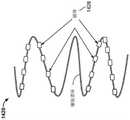
图45示出了根据本说明书的一个实施例的放置的线圈的剪式切割动作;Figure 45 illustrates the scissor cutting action of a placed coil in accordance with one embodiment of the present specification;
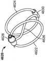
图46A是根据本说明书的一个实施例的用于形成吻合的装置的图示,该装置包括桥接元件和具有相反方向性的环;Figure 46A is an illustration of a device for forming an anastomosis including a bridging element and a loop having opposite orientations according to one embodiment of the present specification;
图46B是根据本说明书的另一实施例的用于形成吻合的另一装置的图示,该装置包括另一桥接元件和具有相反方向性的环;Figure 46B is an illustration of another device for forming an anastomosis including another bridging element and a loop with opposite directionality, according to another embodiment of the present specification;
图46C示出了根据本说明书的一个实施例的图46B所示的盘绕吻合装置的前视图,该装置包括尖端覆盖物;Figure 46C shows a front view of the coiled stapling device shown in Figure 46B including a tip cover according to one embodiment of the present specification;
图46D示出了根据本说明书的一个实施例的图46C所示的盘绕吻合装置的侧视图,该装置包括尖端覆盖物;Figure 46D shows a side view of the coiled anastomotic device shown in Figure 46C including a tip cover according to one embodiment of the present specification;
图46E示出了根据本说明书的一个实施例的图46C所示的盘绕吻合装置的透视图,该装置包括尖端覆盖物;Figure 46E shows a perspective view of the coiled anastomosis device shown in Figure 46C including a tip cover according to one embodiment of the present specification;
图46F示出了根据本说明书的一个实施例的图46C所示的盘绕吻合装置的另一透视图,该装置包括尖端覆盖物;Figure 46F shows another perspective view of the coiled anastomosis device shown in Figure 46C including a tip cover according to one embodiment of the present specification;
图46G示出了根据本说明书的一个实施例的图46C所示的盘绕吻合装置的又一透视图,该装置包括尖端覆盖物;Figure 46G shows yet another perspective view of the coiled anastomotic device shown in Figure 46C including a tip cover according to one embodiment of the present specification;
图47A示出了根据本说明书的一个实施例的盘绕吻合装置,其包括桥接段和向内弯曲的近端和远端;Figure 47A shows a coiled anastomotic device including a bridge segment and inwardly curved proximal and distal ends, according to one embodiment of the present specification;
图47B示出了图47A所示的装置的另一视图;Figure 47B shows another view of the device shown in Figure 47A;
图47C示出了根据本说明书的一个实施例的由SMA金属丝制成的盘绕吻合装置,该装置包括桥接段和向内弯曲的近段和远段;Figure 47C shows a coiled anastomotic device made of SMA wire including a bridge segment and inwardly curved proximal and distal segments according to one embodiment of the present specification;
图47D示出了根据本说明书的一个实施例的图47A所示的装置,其中没有磁体和间隔件放置在SMA金属丝周围;Figure 47D shows the device shown in Figure 47A without the magnet and spacer placed around the SMA wire, according to one embodiment of the present specification;
图47E示出了图47D所示的装置的侧视图;Figure 47E shows a side view of the device shown in Figure 47D;
图47F示出了图47D所示的装置的透视图;Figure 47F shows a perspective view of the device shown in Figure 47D;
图47G示出了图47D所示的装置的另一透视图;Figure 47G shows another perspective view of the device shown in Figure 47D;
图47H示出了图47D所示的装置的又一透视图;Figure 47H shows yet another perspective view of the device shown in Figure 47D;
图47I示出了根据本说明书的一个实施例的图47A所示的装置的侧视图,其中磁体镀有金属材料,并且其中间隔件是O形环;Figure 47I shows a side view of the device shown in Figure 47A, wherein the magnet is plated with a metallic material, and wherein the spacer is an O-ring, according to one embodiment of the present specification;
图47J示出了图47I所示的装置的另一侧视图;Figure 47J shows another side view of the device shown in Figure 47I;
图47K示出了图47I所示的装置的透视图;Figure 47K shows a perspective view of the device shown in Figure 47I;
图47L示出了图47I所示的装置的前视图;Figure 47L shows a front view of the device shown in Figure 47I;
图47M示出了图47I所示的装置的另一透视图;Figure 47M shows another perspective view of the device shown in Figure 47I;
图47N示出了根据本说明书的一个实施例的图47I所示的装置的前视图,其中PTFE垫圈设在“S”形桥接元件周围;Figure 47N shows a front view of the device shown in Figure 47I with a PTFE gasket disposed around an "S" shaped bridge element, according to one embodiment of the present specification;
图47O示出了图47N所示的装置的侧视图;Figure 47O shows a side view of the device shown in Figure 47N;
图47P示出了图47N所示的装置的透视图;Figure 47P shows a perspective view of the device shown in Figure 47N;
图47Q示出了图47N所示的装置的横截面图,分别描绘了图47N所示的装置的各元件;Figure 47Q shows a cross-sectional view of the device shown in Figure 47N, depicting elements of the device shown in Figure 47N, respectively;
图47R示出了图47N所示的装置的磁体包围的SMA金属丝的横截面近视图;Figure 47R shows a cross-sectional close-up view of the SMA wire surrounded by the magnet of the device shown in Figure 47N;
图47S示出了图47N所示的装置的另一透视图;Figure 47S shows another perspective view of the device shown in Figure 47N;
图47T示出了根据本说明书的一个实施例的包括桥接段的盘绕吻合装置的另一视图;Figure 47T shows another view of a coiled anastomosis device including a bridge segment according to one embodiment of the present specification;
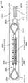
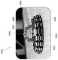
图48A示出了根据本说明书的一个实施例的吻合装置,该吻合装置包括至少部分被收缩的引流元件覆盖的桥接段;Figure 48A shows an anastomotic device according to one embodiment of the present specification, the anastomotic device including a bridge segment at least partially covered by a retracted drainage element;
图48B示出了根据本说明书的另一实施例的吻合装置,该吻合装置包括至少部分被膨胀的引流元件覆盖的桥接段;Figure 48B illustrates an anastomotic device according to another embodiment of the present specification, the anastomotic device including a bridge segment at least partially covered by an expanded drainage element;
图48C示出了根据本说明书的一些实施例的可以与图48A和图48B的吻合装置一起使用的多个引流元件;Figure 48C illustrates a plurality of drainage elements that may be used with the anastomotic device of Figures 48A and 48B, according to some embodiments of the present specification;
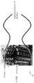
图49A示出了根据本说明书的一个实施例的吻合装置的前视图,该吻合装置包括磁体和覆盖“S”形桥接元件的金属丝网引流元件;Figure 49A shows a front view of an anastomotic device including magnets and wire mesh drainage elements covering "S" shaped bridging elements, according to one embodiment of the present specification;
图49B示出了图49A所示的装置的横截面图;Figure 49B shows a cross-sectional view of the device shown in Figure 49A;
图49C示出了图49A所示的装置的透视图;Figure 49C shows a perspective view of the device shown in Figure 49A;
图49D示出了图49A所示的装置的另一透视图;Figure 49D shows another perspective view of the device shown in Figure 49A;
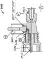
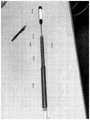
图50A示出了根据本说明书的一个实施例的放置前状态的吻合装置的侧截面图,该吻合装置包括磁体和覆盖桥接元件的金属丝网引流元件;50A shows a side cross-sectional view of an anastomotic device including magnets and wire mesh drainage elements overlying bridging elements in a pre-placement state according to one embodiment of the present specification;
图50B示出了图50A所示的装置的侧视图;Figure 50B shows a side view of the device shown in Figure 50A;
图50C示出了图50A所示的装置的前视图;Figure 50C shows a front view of the device shown in Figure 50A;
图50D示出了图50A所示的装置的透视图;Figure 50D shows a perspective view of the device shown in Figure 50A;
图50E示出了根据本说明书的一个实施例的放置后的图50A至图50D的装置;Figure 50E illustrates the device of Figures 50A-50D after placement, according to one embodiment of the present specification;
图50F示出了根据本说明书的一个实施例的图50E的装置,其中金属丝网引流元件与桥接段分离;Fig. 50F shows the device of Fig. 50E with the wire mesh drainage element separated from the bridging section according to one embodiment of the present specification;
图50G示出了根据本说明书的一个实施例的图50A至图50D所示的装置以及用于将金属丝网引流元件附接到桥接元件的装置的透视图;Figure 50G shows a perspective view of the device shown in Figures 50A-50D and a device for attaching a wire mesh drainage element to a bridging element, according to one embodiment of the present specification;
图50H示出了图50G所示的装置的侧视图;Figure 50H shows a side view of the device shown in Figure 50G;
图50I示出了根据本说明书的一个实施例的放置后状态的吻合装置的前视图,该吻合装置包括被膜覆盖并覆盖线圈的桥接元件的金属丝网引流元件;50I shows a front view of an anastomotic device in a post-placement state including a wire mesh drainage element covered by a membrane and covering a bridging element of a coil, according to one embodiment of the present specification;
图50J示出了根据本说明书的一个实施例的放置前状态的图50I的吻合装置的透视图;Figure 50J shows a perspective view of the anastomotic device of Figure 50I in a pre-placement state according to one embodiment of the present specification;
图50K示出了根据本说明书的一个实施例的放置前状态的吻合装置,该吻合装置包括设在桥接元件上的金属丝网引流元件;Figure 50K shows an anastomotic device in a pre-placement state according to one embodiment of the present specification, the anastomotic device including a wire mesh drainage element provided on a bridging element;
图50L示出了根据本说明书的一个实施例,图50K中所示的金属丝网引流元件在放置后状态下穿过允许立即引流的预定段的视图;Figure 50L shows a view of the wire mesh drainage element shown in Figure 50K passing through a predetermined segment allowing immediate drainage in a post-placement state, according to one embodiment of the present specification;
图50M示出了具有图50L所示的金属丝网引流元件的装置的另一视图,该装置压缩两个相邻结构并在两个相邻结构之间提供即时引流;Figure 50M shows another view of the device with the wire mesh drainage element shown in Figure 50L compressing and providing immediate drainage between two adjacent structures;
图50N示出了根据本说明书的一些实施例的包含金属丝网引流元件的吻合装置的透视图;Figure 50N shows a perspective view of an anastomotic device including a wire mesh drainage element according to some embodiments of the present specification;
图50O示出了包含图50N的金属丝网引流元件的吻合装置的侧视图;Figure 500 shows a side view of an anastomotic device incorporating the wire mesh drainage element of Figure 50N;
图51A示出了根据本说明书的一个实施例的用于将吻合装置输送到体内预定位置的输送装置的手柄;Figure 51A illustrates a handle of a delivery device for delivering an anastomotic device to a predetermined location in the body according to one embodiment of the present specification;
图51B示出了根据本说明书的一个实施例的连接到输送装置的吻合装置的另一手柄,该输送装置用于将吻合装置输送到体内的预定位置;Figure 51B illustrates another handle of an anastomotic device connected to a delivery device for delivering the anastomotic device to a predetermined location in the body according to one embodiment of the present specification;
图51C示出了根据本说明书的一些实施例的吻合装置,该吻合装置包含附接到输送装置的金属丝网引流元件;Figure 51C illustrates an anastomotic device comprising a wire mesh drainage element attached to a delivery device, according to some embodiments of the present specification;
图52A示出了根据本说明书的一个实施例,使用磁压缩装置治疗患者下食管括约肌(LES)的失弛缓症功能障碍;Figure 52A illustrates the use of a magnetic compression device to treat achalasia dysfunction of the lower esophageal sphincter (LES) in a patient according to one embodiment of the present specification;
图52B示出了根据本说明书的一个实施例的由磁压缩装置产生的用于治疗患者的失弛缓症的扩大内腔;Figure 52B illustrates an enlarged lumen created by a magnetic compression device for treating achalasia in a patient, according to one embodiment of the present specification;
图53A示出了根据本说明书的一个实施例,通过使用磁压缩装置在患者的幽门形成扩大开口来治疗胃轻瘫功能障碍;Figure 53A illustrates treatment of gastroparesis dysfunction by using a magnetic compression device to create an enlarged opening in the pylorus of a patient, according to one embodiment of the present specification;
图53B示出了根据本说明书的一个实施例的由磁压缩装置产生的用于治疗患者胃轻瘫的扩大开口;Figure 53B illustrates an enlarged opening created by a magnetic compression device for treating gastroparesis in a patient according to one embodiment of the present specification;
图54A示出了根据本说明书的一个实施例,使用磁压缩装置治疗患者食道的胃肠狭窄;Figure 54A illustrates the use of a magnetic compression device to treat a gastrointestinal stricture of the esophagus of a patient according to one embodiment of the present specification;
图54B示出了根据本说明书的一个实施例的由磁压缩装置产生的用于治疗患者食道狭窄的扩大开口;Figure 54B illustrates an enlarged opening created by a magnetic compression device for treating a patient's esophageal stricture in accordance with one embodiment of the present specification;
图55是示出根据本说明书的一个实施例的进行结肠直肠手术以放置吻合装置的方法的流程图;55 is a flowchart illustrating a method of performing colorectal surgery to place an anastomotic device in accordance with one embodiment of the present specification;
图56是示出根据本说明书的一个实施例的进行胃空肠吻合术以放置吻合装置的方法的流程图;56 is a flowchart illustrating a method of performing a gastrojejunostomy to place an anastomotic device according to one embodiment of the present specification;
图57A示出了根据本说明书的一个实施例的人结肠,其可以被切除以去除患病部分;Figure 57A shows a human colon that can be resected to remove diseased portions, according to one embodiment of the present specification;
图57B示出了人结肠,其中患病部分被去除,得到的结肠的端部被吻合在一起;Figure 57B shows a human colon with the diseased portion removed and the ends of the resulting colon anastomosed together;
图57C示出了根据本说明书实施例的人结肠,其中患病部分被去除,使用磁压缩吻合装置将得到的结肠的端部吻合在一起;Figure 57C shows a human colon with the diseased portion removed and the ends of the resulting colon anastomosed together using a magnetic compression anastomosis device, according to an embodiment of the present specification;
图57D示出了根据本说明书实施例的使用磁压缩吻合装置的不同类型的吻合;Figure 57D illustrates different types of anastomosis using a magnetic compression anastomosis device according to an embodiment of the present specification;
图57E示出了根据本说明书实施例的使用磁压缩吻合装置形成的侧侧结肠吻合;Figure 57E shows a side-to-side colon anastomosis using a magnetic compression anastomosis device according to an embodiment of the present specification;
图57F示出了根据本说明书的实施例的使用磁压缩吻合装置在胆囊和十二指肠之间形成的吻合;Figure 57F shows an anastomosis formed between the gallbladder and duodenum using a magnetic compression anastomosis device according to an embodiment of the present specification;
图58是示出根据本说明书的一个实施例的使用吻合装置来融合被切除结肠的两端的方法的流程图;Figure 58 is a flow chart illustrating a method of fusing two ends of a resected colon using an anastomotic device according to one embodiment of the present specification;
图59是根据本说明书的一个实施例的包括控制机构的吻合输送装置的手柄的框图;59 is a block diagram of a handle of an anastomotic delivery device including a control mechanism according to one embodiment of the present specification;
图60是根据本说明书的实施例的列出使用磁压缩吻合装置形成侧侧吻合的方法中的步骤的流程图;60 is a flowchart listing steps in a method of forming a side-to-side anastomosis using a magnetic compression anastomosis device, according to an embodiment of the present specification;
图61是根据本说明书的实施例的列出使用磁压缩吻合装置形成侧侧吻合的方法中的步骤的流程图;61 is a flowchart listing steps in a method of forming a side-to-side anastomosis using a magnetic compression anastomosis device, according to an embodiment of the present specification;
图62是根据本说明书的实施例的列出使用磁压缩吻合装置形成具有即时流体开放和延迟流体开放的吻合的方法中的步骤的流程图;以及62 is a flowchart listing steps in a method of forming an anastomosis with immediate and delayed fluid opening using a magnetic compression anastomosis device according to an embodiment of the present specification; and
图63是根据本说明书的其他实施例的列出使用磁压缩吻合装置形成具有即时流体开放和延迟流体开放的吻合的方法中的步骤的流程图。63 is a flowchart listing steps in a method of forming an anastomosis with immediate and delayed fluid opening using a magnetic compression anastomosis device, according to other embodiments of the present specification.
具体实施方式Detailed ways
在各种实施例中,形状记忆合金(SMA)或智能合金金属丝用于通过形成吻合的期望形状和尺寸并切割人体内的组织层以产生开口或吻合来形成吻合。在一个实施例中,直段SMA金属丝或纵向拉伸线圈或任何其他基本平面的结构被输送到体内需要吻合的位置。在一个实施例中,SMA金属丝或者是超弹性的或者是热敏的,并且响应于体内的身体热量而卷曲成弹簧状线圈。在各种实施例中,金属丝在室温下具有直的或纵向拉伸的线圈或细长的形状,在人体温度下呈压缩线圈形状,人体温度优选在华氏97.7度至99.5度的范围内。线圈可以在高于华氏96度的任何温度下呈压缩形状。In various embodiments, a shape memory alloy (SMA) or smart alloy wire is used to form an anastomosis by forming the desired shape and size of the anastomosis and cutting tissue layers within the body to create an opening or anastomosis. In one embodiment, a straight length of SMA wire or longitudinally stretched coil or any other substantially planar structure is delivered into the body where an anastomosis is desired. In one embodiment, the SMA wire is either superelastic or thermally sensitive, and coils into a spring-like coil in response to body heat in the body. In various embodiments, the wire has a straight or longitudinally stretched coil or elongated shape at room temperature and a compressed coil shape at human body temperature, preferably in the range of 97.7 degrees to 99.5 degrees Fahrenheit. The coil can take its compressed shape at any temperature above 96 degrees Fahrenheit.
压缩的线圈限定了期望吻合的期望形状和尺寸。压缩线圈对夹在线圈环之间的组织产生压缩力。盘绕动作还导致金属丝造成局部缺血、压力坏死并切割预定组织层,从而在两个相邻的身体组织之间形成吻合。在一个实施例中,在盘绕金属丝的每个同心环上提供多个磁体。设置在相邻环上的磁体相互吸引,从而增强线圈的切割作用。在一些实施例中,压缩力由盘绕金属丝和磁体之间的吸引力共同提供。在一些实施例中,所得吻合的形状主要由线圈的形状决定,而不是由磁体之间的力决定。在各种实施例中,所用磁体的数量和磁体的长度由形成吻合所需的形状、尺寸或时间决定。在各种实施例中,形成吻合所需的时间范围在一天到十四天之间。在各种实施例中,吻合形成在两段SMA金属丝之间、两个或多个磁体之间、或者一段SMA金属丝和一个或多个磁体之间。The compressed coil defines the desired shape and size of the desired fit. The compression coil produces a compressive force on the tissue sandwiched between the coil loops. The coiling action also causes the wire to cause ischemia, pressure necrosis, and cut predetermined layers of tissue, thereby creating an anastomosis between two adjacent bodily tissues. In one embodiment, multiple magnets are provided on each concentric ring of coiled wire. The magnets placed on adjacent rings attract each other, thereby enhancing the cutting action of the coil. In some embodiments, the compressive force is provided by the attractive force between the coiled wire and the magnet. In some embodiments, the shape of the resulting anastomosis is primarily determined by the shape of the coil rather than by the force between the magnets. In various embodiments, the number of magnets used and the length of the magnets are determined by the shape, size or time required to form the fit. In various embodiments, the time required to form an anastomosis ranges from one day to fourteen days. In various embodiments, the anastomosis is formed between two lengths of SMA wire, between two or more magnets, or between a length of SMA wire and one or more magnets.
在各种实施例中,吻合装置包括其上设置有多个磁体的金属丝。在各种实施例中,只需要一个吻合装置来形成期望的吻合。该装置通过输送装置被输送至第一器官的第一内腔,穿过所述第一器官的第一壁并穿过第二器官的第二壁,然后进入所述第二器官的第二内腔,同时仍然至少部分地在所述输送装置上保持输送构型。然后放置吻合装置,使得装置的远端部分设置在所述第二内腔中,近端部分设置在所述第一内腔中。放置后,该装置即卷曲成具有一个或多个线圈的线圈形状,使得线圈的远端部分保持在所述第二内腔中,线圈的近端部分保持在所述第一内腔中。换句话说,仅需要如本说明书的实施例中所述的单个吻合装置来形成期望的吻合,而不是像在现有技术中遇到的那样两个单独的配合装置,其中,第一装置放置在第一器官的第一内腔中,第二装置放置在第二器官的第二内腔中。In various embodiments, the anastomotic device includes a wire having a plurality of magnets disposed thereon. In various embodiments, only one anastomotic device is required to form the desired anastomosis. The device is delivered to the first lumen of the first organ by the delivery device, through the first wall of the first organ and through the second wall of the second organ, and then into the second interior of the second organ cavity while still at least partially maintaining the delivery configuration on the delivery device. The anastomotic device is then placed such that the distal portion of the device is disposed in the second lumen and the proximal portion is disposed in the first lumen. Once placed, the device is crimped into a coil shape with one or more coils such that the distal portion of the coil is retained in the second lumen and the proximal portion of the coil is retained in the first lumen. In other words, only a single anastomotic device as described in the embodiments of this specification is required to form the desired anastomosis, rather than two separate mating devices as encountered in the prior art, where the first device is placed In the first lumen of the first organ, the second device is placed in the second lumen of the second organ.
在各种实施例中,本说明书的吻合装置在放置构型下形成线圈形状,具有至少一个线圈,该线圈具有近端和远端,其中所述近端和所述远端在不同的水平面上。In various embodiments, the anastomotic devices of the present specification are formed in the shape of a coil in a placement configuration, having at least one coil, the coil having a proximal end and a distal end, wherein the proximal end and the distal end are at different levels .
在各种实施例中,吻合装置的放置线圈形状仅通过形状记忆金属丝的作用和/或磁性构件的磁力形成,而不使用任何附加的导向元件、操纵器、径向构件、铰链或开口构件。In various embodiments, the placement coil shape of the anastomotic device is formed solely by the action of the shape memory wire and/or the magnetic force of the magnetic member without the use of any additional guide elements, manipulators, radial members, hinges or opening members .
应当理解,当前公开的实施例具有优于现有技术的几个优点。首先,非放置状态下的金属丝转变为放置状态下的线圈结构会产生自动压缩动作,而不需要手动定位单独的磁性元件,这些磁性元件在固定的放置前或放置后构型中并未拴系在一起或相对于彼此定位。更具体地说,磁性元件的对准是通过它们在金属丝上的固定位置来实现的,金属丝从直的细长构件到线圈形状的自然过渡实现了磁性元件的必要自动对准和组织的压缩。这是因为本文公开的实施例提供的磁性元件是拴系在一起或物理耦接的,使得在放置前和放置后构型中磁性元件相对于彼此具有固定的预定位置。虽然缝线、管或其他构件可以用于建立固定关系,但是优选通过金属丝进行耦接。It should be appreciated that the presently disclosed embodiments have several advantages over the prior art. First, the transition of the wire in the non-placed state to the coil structure in the placed state produces an automatic compression action without the need to manually position individual magnetic elements that are not tethered in a fixed pre-placement or post-placement configuration tied together or positioned relative to each other. More specifically, the alignment of the magnetic elements is achieved by their fixed position on the wire, and the natural transition of the wire from the straight elongated member to the coil shape achieves the necessary self-alignment and organization of the magnetic elements. compression. This is because the embodiments disclosed herein provide that the magnetic elements are tethered together or physically coupled such that the magnetic elements have fixed predetermined positions relative to each other in the pre-placement and post-placement configurations. Although sutures, tubes, or other members may be used to establish the fixed relationship, the coupling is preferably by wire.
因此,装置中的磁体在放置之前和之后都具有固定关系。第一磁体的相对三维位置是已知的,并且相对于第二磁体的三维位置是固定的,无论是在未放置构型(沿着直的金属丝的长度方向)还是放置构型(线圈形状)下。这种固定关系能够实现自动对准,因为在放置之前,用户不需要手动将磁体相对于彼此放置到特定位置,从而在放置后能够正确地连接。换句话说,当装置处于放置构型时,第一线圈中的第一磁体相对于第二线圈中的第二磁体处于预定的固定位置,其中线圈被进行吻合的组织分开。注意,预定的固定位置可以是几个位置中的一个,但是每个位置都是预定和固定的。当相同的装置处于非放置(直的金属丝、非线圈)构型时,相同的第一磁体(沿着金属丝的长度方向)相对于第二磁体(也沿着金属丝的长度方向)处于不同的(但仍然是预定的和固定的)位置。在放置和非放置构型中,这两个相对位置是固定和确定的,与人为干预无关。因此,第一磁体和第二磁体从第一非放置相对固定位置自动转换到第二非放置相对固定位置,并且当人为放置装置影响从非放置状态到放置状态的转换时,人为干预不影响非放置状态下第一磁体相对于第二磁体的预定固定位置和放置状态下第一磁体相对于第二磁体的预定固定位置。Therefore, the magnets in the device have a fixed relationship both before and after placement. The relative three-dimensional position of the first magnet is known, and the three-dimensional position relative to the second magnet is fixed, whether in the unplaced configuration (along the length of the straight wire) or the placed configuration (coil shape )Down. This fixed relationship enables automatic alignment because the user does not need to manually place the magnets in a specific position relative to each other prior to placement so that they can be properly attached after placement. In other words, when the device is in the placement configuration, the first magnet in the first coil is in a predetermined fixed position relative to the second magnet in the second coil, wherein the coils are separated by the tissue undergoing anastomosis. Note that the predetermined fixed position may be one of several positions, but each position is predetermined and fixed. When the same device is in a non-placed (straight wire, non-coil) configuration, the same first magnet (along the length of the wire) relative to the second magnet (also along the length of the wire) is in Different (but still predetermined and fixed) locations. In the placed and non-placed configurations, these two relative positions are fixed and determined, independent of human intervention. Therefore, the first magnet and the second magnet are automatically switched from the first non-placement relative fixed position to the second non-placement relative fixed position, and when the human placement device affects the transition from the non-placement state to the placement state, human intervention does not affect the non-placement state. The predetermined fixed position of the first magnet relative to the second magnet in the placed state and the predetermined fixed position of the first magnet relative to the second magnet in the placed state.
相比之下,现有技术教导了必须相对于彼此手动对准以实现正确的压缩力的单独的磁性组件(因为它们没有以固定的方式,即放置前或放置后形状中的至少一种或两种形状,物理耦接)。这意味着在非放置状态下,第一磁体组件相对于第二磁体组件没有预定的固定位置,因为它每次都不同,取决于组件如何使用。这也意味着在放置状态下,第一磁体相对于第二磁体没有预定的固定位置。In contrast, the prior art teaches separate magnetic assemblies that must be manually aligned relative to each other to achieve the correct compressive force (because they are not in a fixed manner, i.e. at least one of a pre-placement or post-placement shape or two shapes, physically coupled). This means that in the non-placed state, the first magnet assembly has no predetermined fixed position relative to the second magnet assembly, as it is different each time, depending on how the assembly is used. This also means that in the placed state, the first magnet has no predetermined fixed position relative to the second magnet.
在操作上,这种自对准特性提高了装置的安全性。身体的各个部分都受到组织运动的影响,诸如胃肠道的蠕动,它可以移动或分离压迫组织的两个相对的磁体。因为现有技术的装置包括两个独立移动的磁性结构,它们极有可能在不同构型或位置分离和重新连接,从而可能在错误的组织中形成吻合,诸如在患者胃肠道的错误部分。在当前公开的实施例中,如果第一线圈上的第一磁性元件附接到第二线圈上的第二磁性元件之后,两个磁性元件随后分离,该分离将只是暂时的,两个磁性元件会自动地重新附接到目标组织区域上,而不需要人工干预。首先,如上所述,两个磁性元件具有固定关系。第二,它们相对于目标组织处于固定位置,因其通过刺穿目标组织而被插入到位。因此,如果暂时分离,磁体并不会移动(因为下面的金属丝已经刺穿目标组织),一旦干扰性动作减弱,它们将盘绕回到放置构型。因此,被目标组织分开的相对线圈上的两个磁性元件在至少70%的时间内,最可能在至少90%、95%和99%的时间内,在被解剖动作暂时分开之后,自动重新附接。Operationally, this self-aligning feature increases the safety of the device. Various parts of the body are affected by tissue movement, such as the peristalsis of the gastrointestinal tract, which can move or separate two opposing magnets that compress the tissue. Because prior art devices include two independently moving magnetic structures, they are highly likely to detach and reconnect in different configurations or locations, potentially creating an anastomosis in the wrong tissue, such as in the wrong part of a patient's gastrointestinal tract. In the presently disclosed embodiment, if after the first magnetic element on the first coil is attached to the second magnetic element on the second coil, the two magnetic elements are subsequently separated, the separation will only be temporary, the two magnetic elements Automatically reattach to the target tissue area without manual intervention. First, as mentioned above, the two magnetic elements have a fixed relationship. Second, they are in a fixed position relative to the target tissue as they are inserted into place by piercing the target tissue. Thus, if temporarily disengaged, the magnets do not move (because the underlying wire has pierced the target tissue), and once the disturbing motion subsides, they will coil back into the placement configuration. Thus, two magnetic elements on opposing coils separated by the target tissue automatically reattach at least 70% of the time, and most likely at least 90%, 95%, and 99% of the time, after being temporarily separated by a dissecting action catch.
前述耦接结构也利于放置过程。医生不必在要进行吻合的组织的两个相对侧上放置两个单独的组件,而只需放置单个装置,该装置用于对要进行吻合的组织进行初始穿刺,然后自动盘绕,以提供必要的压缩力。The aforementioned coupling structure also facilitates the placement process. Instead of placing two separate components on opposite sides of the tissue to be anastomosed, the physician places a single device that is used to make an initial puncture of the tissue to be anastomosed and then automatically coils to provide the necessary compressive force.
第二,本文公开的实施例优选地使用实心金属丝,诸如镍钛诺丝,以将磁性元件彼此整体耦接。这具有几个优点,包含1)能够提供将电烧灼穿刺功能集成到吻合装置本身中的导线机构;2)避免使用管或具有任何从中穿过的中空内腔的结构,这些结构制造更复杂,更难以可靠地放置,还会导致装置过厚或具有外形过小的磁体,从而减少可用的压缩力的量;以及3)允许医生将装置放置在较厚的装置或导管不能到达的位置,诸如假性囊肿。虽然实心金属丝是优选实施例,但是所有当前公开的实施例都可以使用空心管,诸如空心镍钛诺丝,导丝可以穿过该空心管以定位该装置。Second, the embodiments disclosed herein preferably use solid wire, such as Nitinol wire, to integrally couple the magnetic elements to each other. This has several advantages, including 1) the ability to provide a wire mechanism that integrates the electrocautery penetration function into the anastomotic device itself; 2) avoids the use of tubes or structures with any hollow lumen therethrough, which are more complex to manufacture, More difficult to place reliably, also results in devices that are too thick or have under-profiled magnets, reducing the amount of compressive force available; and 3) allows physicians to place devices in locations that thicker devices or catheters cannot reach, such as pseudocyst. While a solid wire is the preferred embodiment, all presently disclosed embodiments may use a hollow tube, such as a hollow Nitinol wire, through which a guide wire may be passed to position the device.
第三,本文公开的实施例教导了一种具有多个磁性元件的金属丝,这些磁性元件优选不固定地附接到金属丝上,而是紧密地定位在金属丝上,并且使用非铁磁间隔件与相邻的磁性元件分离。这有几个好处。所公开的装置制造起来更简单,因为每个磁性元件不需要使用焊料、棘爪、调整片、胶水、焊接或摩擦配合单独固定到金属丝上。相反,磁性元件可以单独具有内腔,以允许更大的公差,并通过内腔串在金属丝上,并且使用非铁磁间隔件与相邻的磁性元件分离,避免了将磁性元件附接到金属丝的任何额外的固定步骤。这使得每个磁性元件能够相对于同一金属丝上的其他磁性元件具有固定的位置,而不必将每个磁性元件附接到金属丝上。此外,其间具有非铁磁间隔件的各个磁性元件的固定位置(由此产生磁性元件和非铁磁间隔件的交替序列)防止了磁体的不必要聚集或移动。虽然现有技术公开了使用磁性元件的护套或突起,但是这种结构不能防止磁体聚集或从优选的构型或排列中整体移出。事实上,磁性元件优选具有光滑的表面(没有凸起部分),以实现更灵活的对准,并且不必将非凸起部分与凸起部分对准。然而,应该理解的是,在一个不太优选的实施例中,每个磁性元件可以附接到金属丝上,并且通过空格(而不是由例如塑料或其他医学上可接受的材料制成的物理的非铁磁间隔件)与相邻的磁性元件分开。Third, the embodiments disclosed herein teach a wire having a plurality of magnetic elements that are preferably not fixedly attached to the wire, but are positioned closely on the wire, and use non-ferromagnetic The spacers are separated from adjacent magnetic elements. This has several benefits. The disclosed device is simpler to manufacture as each magnetic element does not need to be individually secured to a wire using solder, detents, tabs, glue, soldering or friction fit. Conversely, the magnetic elements can have lumens alone to allow for greater tolerances and be strung on the wire through the lumens and separated from adjacent magnetic elements using non-ferromagnetic spacers, avoiding the need to attach the magnetic element to the Any additional fixing steps for the wire. This enables each magnetic element to have a fixed position relative to other magnetic elements on the same wire without having to attach each magnetic element to the wire. Furthermore, the fixed position of the individual magnetic elements with the non-ferromagnetic spacers in between (thus creating an alternating sequence of magnetic elements and non-ferromagnetic spacers) prevents unwanted aggregation or movement of the magnets. While the prior art discloses the use of sheaths or protrusions of magnetic elements, such structures do not prevent the magnets from agglomerating or dislodging in their entirety from a preferred configuration or arrangement. In fact, the magnetic element preferably has a smooth surface (without raised parts) to allow for a more flexible alignment and it is not necessary to align the non-raised parts with the raised parts. It should be understood, however, that in a less preferred embodiment, each magnetic element may be attached to a wire and pass through a space (rather than a physical material made of, for example, plastic or other medically acceptable material). non-ferromagnetic spacers) are separated from adjacent magnetic elements.
第四,所公开的线圈结构允许应用多个磁性层,从而增加组织表面上的压缩力,而不会增加医疗过程的复杂性。如果使用现有技术的装置,必须在组织表面的两侧手动匹配多个单独的、物理上分离的磁性组件,以实现当前公开的线圈结构能够自动实现的效果:在组织两侧用多个磁性层压缩组织,这些磁性层彼此自动对齐,并且在放置前和放置后构型中都处于固定的相对位置。具体而言,本说明书的装置和方法仅需要单个装置和单个路径来形成吻合。现有技术的方法需要通向吻合区域的两条单独的通路。此外,现有技术的装置需要两个单独的植入物,因此医生需要通过内窥镜或腹腔镜进入两个不同的路径。两条独立且不同的路径不仅创伤更大,而且需要额外的步骤。本说明书的装置和方法不需要现有技术方法所必需的额外步骤。利用本说明书的装置和方法,一个路径就可以完成吻合装置两侧的定位。因此,本说明书的装置和方法具有优于现有技术的优点,即使用单个植入程序并且不需要第二步骤定位吻合装置的两侧。Fourth, the disclosed coil structure allows the application of multiple magnetic layers, thereby increasing the compressive force on the tissue surface, without increasing the complexity of the medical procedure. If prior art devices are used, multiple separate, physically separate magnetic assemblies must be manually matched on both sides of the tissue surface to achieve what the currently disclosed coil structure can automatically achieve: multiple magnetic Layers compress the tissue, these magnetic layers self-align with each other and are in fixed relative positions in both the pre-placement and post-placement configurations. Specifically, the devices and methods of the present specification require only a single device and a single pathway to form an anastomosis. Prior art methods require two separate accesses to the anastomotic region. Furthermore, prior art devices require two separate implants, so the physician needs to access two different routes through the endoscope or laparoscope. Two separate and distinct paths are not only more traumatic, but require additional steps. The apparatus and methods of the present specification do not require additional steps necessary for prior art methods. Using the device and method of the present specification, positioning of both sides of the anastomotic device can be accomplished in one path. Thus, the devices and methods of the present specification have the advantage over the prior art of using a single implantation procedure and not requiring a second step to position both sides of the anastomotic device.
术语“和/或”是指一个或所有列出的元素或任何两个或多个列出的元素的组合。The term "and/or" refers to one or all of the listed elements or a combination of any two or more of the listed elements.
在本申请的描述和权利要求中,词语“包括”、“包含”和“具有”中的每一个及其各种形式不一定限于该词语可能关联的列表中的成员。In the description and claims of this application, each of the words "comprising," "comprising," and "having," and their various forms, are not necessarily limited to the members of the list to which the word may be associated.
除非另有说明,“一”、“一个”、“该”、“一个或多个”和“至少一个”可互换使用,表示一个或多个。Unless stated otherwise, "a," "an," "the," "one or more," and "at least one" are used interchangeably to mean one or more.
术语“放置前”或“输送”构型是指其上放置磁性元件或构件的实心金属丝基本上是直的或线性的构型。The term "pre-placement" or "delivery" configuration refers to a substantially straight or linear configuration of the solid wire on which the magnetic element or member is placed.
术语“放置后”或“放置”构型是指其上放置磁性元件或构件的实心金属丝基本上盘绕或呈螺旋形状的构型。The term "post-placement" or "placement" configuration refers to a substantially coiled or helical-shaped configuration of the solid wire on which the magnetic element or member is placed.
术语“线圈”指的是整个磁性吻合装置,术语“环”指的是“线圈”的单个完整的金属丝圈,带有或不带有磁体和间隔物。The term "coil" refers to the entire magnetic anastomotic device, and the term "loop" refers to a single complete wire loop of the "coil", with or without magnets and spacers.
对于本文公开的包含离散步骤的任何方法,这些步骤可以以任何可行的顺序进行。并且,在适当的情况下,两个或多个步骤的任何组合可以同时进行。For any method disclosed herein that contains discrete steps, the steps can be performed in any practicable order. Also, where appropriate, any combination of two or more steps may be performed simultaneously.
此外,在本文中,通过端点对数值范围的列举包含该范围内包括的所有整数或分数(例如,1至5包含1、1.5、2、2.75、3、3.80、4、5等)。除非另有说明,否则说明书和权利要求书中使用的表示部件数量、分子量等的所有数字应理解为在所有情况下都被术语“大约”修饰。因此,除非另有相反指示,否则说明书和权利要求书中阐述的数值参数是近似值,其可以根据本发明寻求获得的期望性质而变化。至少,并且不试图将等同原则限制于权利要求的范围,每个数字参数应该至少根据所报告的有效数字的数量并且通过应用普通的舍入技术来解释。Furthermore, herein, the recitation of numerical ranges by endpoints includes all integers or fractions subsumed within that range (eg, 1 to 5 includes 1, 1.5, 2, 2.75, 3, 3.80, 4, 5, etc.). Unless stated otherwise, all numbers used in the specification and claims indicating the number of components, molecular weights, etc. should be understood to be modified in all instances by the term "about". Accordingly, unless indicated to the contrary, the numerical parameters set forth in the specification and claims are approximations that can vary depending upon the desired properties sought to be obtained by the present invention. At the very least, and without attempting to limit the doctrine of equivalents to the scope of the claims, each numerical parameter should at least be construed in light of the number of reported significant digits and by applying ordinary rounding techniques.
虽然阐述本发明广泛范围的数值范围和参数是近似值,但是在具体示例中阐述的数值被尽可能精确地报告。然而,所有数值固有地含有一个范围,该范围必然由在它们各自的测试测量中发现的标准偏差产生。也就是说,应当理解,本文提供的尺寸是至关重要的,因为它们使得装置足够小,以输送到身体中的所需物理空间,同时仍然具有足够的压缩力来形成吻合。Notwithstanding that the numerical ranges and parameters setting forth the broad scope of the invention are approximations, the numerical values set forth in the specific examples are reported as precisely as possible. All numerical values, however, inherently contain a range necessarily resulting from the standard deviation found in their respective testing measurements. That is, it should be understood that the dimensions provided herein are critical as they allow the device to be small enough to be delivered to the desired physical space in the body, while still having sufficient compressive force to form an anastomosis.
本说明书针对多个实施例。提供以下公开内容是为了使本领域普通技术人员能够实践本发明。本说明书中使用的语言不应被解释为对任何一个特定实施例的一般否定,也不应被用来将权利要求限制在其中使用的术语的含义之外。在不脱离本发明的精神和范围的情况下,本文定义的一般原理可以应用于其他实施例和应用。此外,所使用的术语和措辞是为了描述示例性实施例的目的,不应被认为是限制性的。因此,本发明将被赋予最宽的范围,该范围包括与所公开的原理和特征一致的许多替换、修改和等同物。为了清楚起见,没有详细描述与本发明相关的技术领域中已知的技术材料相关的细节,以免不必要地模糊本发明。This specification is directed to various embodiments. The following disclosure is provided to enable any person of ordinary skill in the art to practice the present invention. The language used in this specification should not be construed as a general disavowal of any one particular embodiment, nor should it be used to limit the claims beyond the meaning of the terms used therein. The general principles defined herein may be applied to other embodiments and applications without departing from the spirit and scope of the invention. Also, the terminology and phraseology used is for the purpose of describing example embodiments and should not be regarded as limiting. Therefore, the present invention is to be accorded the broadest scope encompassing numerous alternatives, modifications and equivalents consistent with the principles and features disclosed. For the purpose of clarity, details related to technical material that is known in the technical fields related to the invention have not been described in detail so as not to unnecessarily obscure the invention.
这里应该注意的是,与特定实施例相关联描述的任何特征或部件可以与任何其他实施例一起使用和实现,除非另外明确指出。It should be noted here that any feature or component described in association with a particular embodiment can be used and implemented with any other embodiment, unless expressly stated otherwise.
图1示出了根据本说明书的一个实施例的在人体内盘绕的直的SMA金属丝102。金属丝102由诸如镍钛诺的SMA材料制成。形状记忆合金,也可称为SMA、智能金属、记忆金属、记忆合金、肌肉线和/或智能合金,是一种“记得”原始形状的合金,其在变形后可通过加热恢复到变形前形状。镍钛合金加热后从马氏体变成奥氏体。在一个实施例中,SMA金属丝102由铜-铝-镍合金制成。在另一实施例中,SMA金属丝102由镍钛合金制成。在一个实施例中,金属丝102的直径在0.1至6mm的范围内,在未盘绕位置具有小于10%的最大应变,在盘绕位置具有从5mm至60mm的最大横截面尺寸。在一个实施例中,对于5%的应变,当金属丝直径小于0.75mm、在0.75mm和1mm之间和大于1mm时,盘绕金属丝的直径分别小于15mm、在15mm和20mm之间和大于20mm。在一个实施例中,对于10%的应变,当金属丝直径为1mm、1.25mm、1.5mm、1.7mm、2mm和2.5mm时,盘绕金属丝的直径分别为10mm、12.5mm、15mm、17mm、20mm、25mm和45mm。在一个实施例中,对于6%的应变,当金属丝直径为0.6mm、0.75mm、0.9mm、1.02mm、1.2mm和1.5mm时,盘绕金属丝的直径分别为10mm、12.5mm、15mm、17mm、20mm、25mm和45mm。此外,在各种实施例中,金属丝102在输送到体内时盘绕成至少2个环。FIG. 1 shows a
As和Af是马氏体向奥氏体转变开始和结束的温度。当插入人体并放置在吻合部位时,金属丝102响应于人体相对于室温的较高温度而改变形状并盘绕成104或106。在各种实施例中,金属丝102的直径在0.1mm至10mm的范围内,金属丝102的长度在1cm至250cm的范围内。在一些实施例中,如参考图23A和图23B所解释的,环108设置在金属丝的一个或多个端部,用于与输送导管附接。在各种实施例中,金属丝的Af温度小于或等于40℃,金属丝的As温度小于或等于37℃。在各种实施例中,处于马氏体形状的镍钛诺丝上的应变小于或等于10%。在一个实施例中,线圈具有半径为r的圆形横截面,其中线圈的周长为2πr,线圈的面积为πr2,其中线圈产生半径约为r且面积为πr2的吻合口。在一些实施例中,金属丝的Af温度(转变温度)大于或等于37℃,并且提供用于加热金属丝的机构来帮助加热金属丝,以将金属丝从其马氏体形状转变为奥氏体形状。在一个实施例中,用于加热金属丝的机构包括使电流通过金属丝。在一些实施例中,金属丝的Af温度(转变温度)大于或等于20℃。As and Afare the temperatures at which the martensite to austenite transformation begins and ends. When inserted into the human body and placed at the anastomotic site, the
图2示出了根据本说明书的一个实施例的穿过SMA金属丝的环204、206的多个磁体202a、202b、202c、202d、202e、202f。磁体202a、202b、202c、202d、202e、202f穿过线圈200的环204和206。在一个实施例中,线圈200是镍钛诺丝,其响应于温度变化而盘绕。排斥力作用在穿在同一环204上的相邻磁体202a、202b和202c之间,从而保持所述磁体之间的预定距离。类似地,排斥力作用在穿在同一环206上的相邻磁体202d、202e和202f之间,从而保持这些磁体之间的预定距离。吸引力作用在穿在环204上的磁体和线圈206上的磁体之间。因此,磁体202a和202d之间、磁体202b和202e之间以及磁体202c和202f之间存在吸引力。相邻环上的磁体之间的吸引力在线圈的环之间产生压缩力207,将环拉在一起以切割环之间的组织并形成吻合。在各种实施例中,压缩力在0.1至0.5N的范围内,并且施加到夹在环之间的组织层的相关压力在0.15psi至145psi(0.001至1MPa)的范围内。在一个实施例中,至少两个磁体与线圈200的两个相邻环相耦接,并且金属丝盘绕成至少两个环。在一个实施例中,磁体是覆盖有生物相容性材料的稀土磁体,诸如金、镍、特氟隆、聚对二甲苯、铜、锌、硅树脂、环氧树脂或钛。在一个实施例中,线圈200包含RFID标签210,以帮助线圈200在放置之后和吻合形成期间的定位。使用RFID扫描仪,可以通过与嵌入式RFID标签的通信来识别线圈的位置,以确定线圈在患者体内的精确位置,而不需要用于可视化的辐射。在一些实施例中,磁体的等级为N35或更高。Figure 2 shows a plurality of
在一个实施例中,镍钛诺线圈在组织上施加小于或等于50mmHg(0.97psi)的压力,组合线圈和磁体在组织上施加大于50mmHg(0.97psi)的压力。在另一实施例中,镍钛诺线圈在组织上施加小于或等于80mmHg(1.57psi)的压力,组合线圈和磁体在组织上施加大于80mmHg(1.57psi)的压力。在又一实施例中,镍钛诺线圈在组织上施加小于或等于120mmHg(2.32psi)的压力,组合线圈和磁体在组织上施加大于120mmHg(2.32psi)的压力。在又一实施例中,镍钛诺线圈在组织上施加小于或等于150mmHg(2.90psi)的压力,组合线圈和磁体在组织上施加大于150mmHg(2.90psi)的压力。在另一实施例中,镍钛诺线圈在组织上施加小于或等于200mmHg(3.86)的压力,组合线圈和磁体在组织上施加大于200mmHg(3.86)的压力。在一个实施例中,每个线圈组织界面处的线圈压力足以阻止组织中超过50%的毛细流动。在一个实施例中,线圈在超过线圈周长的四分之一处产生大于或等于20mmHg(0.39psi)的压力,并且压力相对均匀地分布在每个线圈环的两个半圆之间。在一个实施例中,在每个线圈环相对侧的两个或多个点处,压力大于或等于20mmHg(0.39psi)。In one embodiment, the Nitinol coil exerts less than or equal to 50 mmHg (0.97 psi) of pressure on the tissue and the combined coil and magnet exerts greater than 50 mmHg (0.97 psi) of pressure on the tissue. In another embodiment, the Nitinol coil exerts less than or equal to 80 mmHg (1.57 psi) of pressure on the tissue and the combined coil and magnet exerts greater than 80 mmHg (1.57 psi) of pressure on the tissue. In yet another embodiment, the Nitinol coil exerts a pressure on the tissue less than or equal to 120 mmHg (2.32 psi) and the combined coil and magnet exert a pressure on the tissue greater than 120 mmHg (2.32 psi). In yet another embodiment, the Nitinol coil exerts less than or equal to 150 mmHg (2.90 psi) of pressure on the tissue and the combined coil and magnet exerts greater than 150 mmHg (2.90 psi) of pressure on the tissue. In another embodiment, the Nitinol coil exerts less than or equal to 200 mmHg (3.86) pressure on the tissue and the combined coil and magnet exerts greater than 200 mmHg (3.86) pressure on the tissue. In one embodiment, the coil pressure at the tissue interface of each coil is sufficient to prevent more than 50% of capillary flow in the tissue. In one embodiment, the coil generates a pressure greater than or equal to 20 mmHg (0.39 psi) over a quarter of the coil circumference, and the pressure is distributed relatively evenly between the two semicircles of each coil loop. In one embodiment, the pressure is greater than or equal to 20 mmHg (0.39 psi) at two or more points on opposite sides of each coil loop.
在一个实施例中,如上所述,大部分压缩力最初由SMA线圈提供。然而,随着磁体物理上更紧密地会聚在一起,磁压缩力超过由镍钛诺线圈提供的压缩力,并驱动吻合形成。在一些实施例中,在放置之前,通过使电流流过线圈加热线圈来加速吻合形成的过程,从而损伤/凝固或消融介入组织。In one embodiment, as described above, most of the compressive force is initially provided by the SMA coil. However, as the magnets are physically brought closer together, the magnetic compressive force exceeds the compressive force provided by the Nitinol coil and drives the anastomosis to form. In some embodiments, prior to placement, the process of anastomosis formation is accelerated by passing current through the coil to heat the coil to damage/coagulate or ablate the intervening tissue.
图3A示出了根据本说明书的一个实施例,使用输送导管或针通过内窥镜刺穿有胆囊炎和胆结石304的胆囊302,以放置SMA吻合装置从而形成吻合。有胆结石304的胆囊302被输送导管或针306刺穿,该输送导管或针306通过插入患者十二指肠310的内窥镜308输送。导管或针306刺穿十二指肠310和胆囊302的壁,以便使用本说明书的装置将胆囊302与十二指肠310连接以形成吻合,用于向胆囊302提供引流并移除胆结石304。在一个实施例中,内窥镜308是超声内镜,穿刺是在超声显像下进行的。在另一实施例中,内窥镜308是十二指肠镜,穿刺在荧光显影下进行。Figure 3A illustrates the use of a delivery catheter or needle to pierce a
图3B示出了根据本说明书的一个实施例的在图3A所示的胆囊302和十二指肠310之间放置并形成吻合的SMA线圈312。在一个实施例中,包括镍钛诺丝的SMA线圈312通过内窥镜308输送通过胆囊302壁中由导管或针刺穿的孔。由于暴露于身体热量,镍钛诺丝改变形状并盘绕起来,将胆囊302壁和十二指肠310壁的组织保持在如图3B所示的线圈312环之间,从而在胆囊302和十二指肠310之间形成吻合。金属丝312的盘绕导致压缩力作用在夹在线圈之间的组织上,从而切割组织以形成吻合。在一个实施例中,磁体可以穿入线圈312中,以进一步增加压缩力,如图2和图3C所示。在各种实施例中,吻合在一段时间内形成,以有充足的时间使吻合的新血管形成,从而实现没有明显泄漏的稳固且稳定的吻合。Figure 3B shows an
图3C示出了根据本说明书的另一实施例的SMA线圈332,其穿有磁体334,在胆囊322和十二指肠320之间形成吻合。在一个实施例中,包括镍钛诺的SMA线圈332穿有放置在不同/相邻线圈环中的磁体334。放置在不同线圈环中的磁体334相互吸引,从而进一步增加线圈332中的压缩力,并加速或改善胆囊和十二指肠壁的切割以形成吻合口。在一个实施例中,在胆囊和/或十二指肠的壁中形成一个或多个切口或一个或多个造口,以放置穿有磁体334的SMA线圈332,用于形成吻合。FIG. 3C shows an
图3D是根据本说明书的一个实施例的穿有图3C所示的磁体的SMA线圈332的近视图。线圈332在环336中穿有磁体334a和334b,在环338中穿有磁体334c和334d。磁体334a和334b的磁极被布置成使得磁体彼此排斥,从而在环336上保持彼此之间恒定的预定距离。类似地,磁体334c和334d的磁极被布置成使得磁体彼此排斥,从而在环338上保持彼此之间恒定的预定距离。磁体334a和334c的磁极被布置成使得磁体彼此吸引,从而将线圈332的环336和338拉得更近,并增加线圈332施加在夹在线圈332环之间的组织层上的压缩力。类似地,压缩力由磁体334b和334d之间的吸引力造成。随着磁体切割组织并越来越近,压缩力逐渐增加,一旦两个壁有时间融合在一起,就慢慢加速切割动作和吻合形成。这种方法减少了在吻合进行得太快的情况下发生泄漏的机率,没有留出足够的时间使两个相邻的壁并置和融合。Figure 3D is a close-up view of the
图4A示出了根据本说明书的一个实施例的吻合过程的第一阶段。如图所示,器官壁402和404夹在线圈406的相邻环407、409之间。在一个实施例中,线圈406由SMA材料制成,诸如镍钛诺,并且作为一根直的金属丝或细长的相对直的线圈输送到器官中,由于暴露于身体热量,该线圈改变形状以形成预定形状和尺寸的线圈,使得相邻的器官壁被夹在线圈环之间。参考图3A,在一个实施例中,器官壁402是胆囊302的壁,器官壁404是十二指肠410的相邻壁。参考图4A,磁体408和410分别与线圈406的环412和414耦接。磁体408和410的磁极被布置成使得磁体彼此吸引,从而将环407、412和409、414拉得更近,并增加线圈406施加在器官壁402和404上的压缩力。随着时间的推移,SMA金属丝施加相对稳定的力,而磁体将施加逐渐增加的压缩力,该压缩力随着吻合形成而加速,从而导致壁的初始融合,并且一旦两个壁融合,就切割穿过壁。在一些实施例中,压缩表面由两个相对的磁体或一根金属丝和一个磁体提供。Figure 4A illustrates the first stage of an anastomosis procedure according to one embodiment of the present specification. As shown,
图4B示出了根据本说明书的一个实施例的图4A所示的吻合过程的第二阶段。如图4B所示,线圈406的环407、412和409、414通过将磁体408、410吸引在一起的磁力413而被拉得更近,从而压缩环407和409之间的器官壁402和404,导致局部缺血,随后融合两个器官壁的新血管形成。图4C示出了根据本说明书的一个实施例的图4A和图4B所示的吻合过程的第三阶段。如图所示,由于磁体408、410之间的磁力413,线圈406的压缩力进一步增强,导致线圈中心的组织完全缺血、凋亡和缺血性坏死,并导致线圈406的环407、409和/或磁体408切割器官壁402、404。图4D示出了根据本说明书的一个实施例,作为图4A、图4B和图4C所示的吻合过程的第四阶段,也是最终阶段的吻合的形成。如图所示,由于线圈切割器官壁402、404而形成开口/吻合415,然后线圈脱落并被自然穿过,而不需要内窥镜检查。在一个实施例中,线圈被设计成便于在顺行或逆行切割壁之后通过。在另一实施例中,线圈被配置为保持在吻合中,随后使用内窥镜移除。Figure 4B illustrates the second stage of the anastomosis process shown in Figure 4A, according to one embodiment of the present specification. As shown in Figure 4B, the
图5示出了表格500,其示出了根据本说明书的一个实施例的用于形成吻合的吻合装置的示例性尺寸。列502示出了以mm为单位的线圈的示例性直径,而列504、506、508、510和512示出了以cm为单位的分别盘绕成1、2、4、8和16环的金属丝的相应示例性长度。吻合的预定直径在0.5cm和5cm之间,线圈金属丝的预定长度在3cm到250cm之间。吻合的优选直径取决于具体器官,胆囊为1-2cm,胆管为0.5-1cm,囊肿胃切除术或囊肿空肠吻合术为1-2cm,肠肠吻合术的胃空肠吻合术为2-5cm。然而,这些是代表性的数字,在实践中,线圈的直径将基于器官的直径和所治疗的适应症来确定。在各种实施例中,线圈的直径小于或等于待吻合器官的直径。例如,在胆管吻合、小肠吻合、结肠吻合、胆囊吻合、假性囊肿吻合和血管吻合的情况下,线圈的直径分别小于或等于10mm、小于或等于30mm、小于或等于60mm、小于或等于30mm、小于或等于30mm和小于或等于25mm。环的优选数量将取决于形成吻合所需的总磁力,其又取决于被吻合的器官壁的总厚度。在一些实施例中,通过使用内窥镜在体内输送SMA金属丝,因此,金属丝的长度需要小于内窥镜的长度。在一个实施例中,SMA金属丝的长度小于250cm,或者更具体地小于75cm。在SMA金属丝的长度为75cm的实施例中,获得的线圈环的数量为8个。在一个实施例中,其中SMA金属丝的长度为100cm,获得16个直径为2cm的线圈环或8个直径为4cm的线圈环。在SMA金属丝的长度为250cm的实施例中,获得16个直径为5cm的线圈环。此外,在各种实施例中,一个装置具有两个线圈环,每个线圈环包括8个磁体,另一个装置具有8个线圈环,每个线圈环包括2个磁体,每个装置在夹在相应线圈环之间的组织上引起相同的压缩力。组织中所需的吻合尺寸决定了每个线圈环的直径,而线圈环的直径又决定了与引起吻合的SMA金属丝结合使用的磁体的数量(及其长度)。所需的压缩力是大于组织中毛细血管血流量的压缩压力。在各种实施例中,需要由SMA线圈在被吻合的组织上施加预定的最小压力,并且所述压力需要沿着每个线圈环分布。在一个实施例中,所述压力至少沿着每个线圈环上的四个点施加。在其他实施例中,根据环的尺寸,沿着每个环的圆周的两个或八个点施加压力。FIG. 5 shows a table 500 showing exemplary dimensions of an anastomotic device for forming anastomosis according to one embodiment of the present specification.
在各种实施例中,用于吻合的SMA金属丝的直径在0.1mm至6mm的范围内,而线圈的节距小于10mm。在各种实施例中,SMA线圈的最大横截面直径在5mm至50mm的范围内,其中线圈中的环的数量为至少两个且最大为100个,并且线圈金属丝的总长度小于或等于250cm。In various embodiments, the diameter of the SMA wire used for anastomosis is in the range of 0.1 mm to 6 mm, and the pitch of the coils is less than 10 mm. In various embodiments, the maximum cross-sectional diameter of the SMA coil is in the range of 5mm to 50mm, wherein the number of loops in the coil is at least two and a maximum of 100, and the total length of the coil wire is less than or equal to 250cm .
直线位置(马氏体形状)的金属丝中的最大应变小于或等于10%。在各种实施例中,线圈的直径将决定金属丝的直径,直径小于或等于15mm的线圈最好用直径小于或等于0.75mm的金属丝来制造,直径为15-25mm的线圈最好用直径为0.75-1.0mm的金属丝来制造,直径大于或等于25mm的线圈最好用直径大于或等于1mm的金属丝来制造。在各种实施例中,在线圈-组织边界界面,磁体和SMA金属丝造成至少0.15psi的压力,更优选至少1.0psi的压力,最优选至少2.50psi的压力,以切断组织中的血液供应。在一些实施例中,施加高达4.0psi的压力。在各种实施例中,在线圈-组织边界界面处,磁体和SMA金属丝造成等于或小于145psi的压力。The maximum strain in the wire in the straight position (martensitic shape) is less than or equal to 10%. In various embodiments, the diameter of the coil will determine the diameter of the wire, coils with a diameter of 15mm or less are preferably made of wire with a diameter of less than or equal to 0.75mm, and coils with a diameter of 15-25mm are preferably made with a diameter of 0.75mm or less. Made for 0.75-1.0mm wire, coils with a diameter greater than or equal to 25mm are preferably made with wire with a diameter greater than or equal to 1mm. In various embodiments, the magnet and SMA wire create a pressure of at least 0.15 psi, more preferably at least 1.0 psi, and most preferably at least 2.50 psi at the coil-tissue boundary interface to cut off the blood supply in the tissue. In some embodiments, up to 4.0 psi of pressure is applied. In various embodiments, at the coil-tissue boundary interface, the magnet and the SMA wire cause a pressure equal to or less than 145 psi.
在各种实施例中,与SMA线圈耦接的磁体是稀土或永磁体,其中每个磁体具有0.2mm至7mm范围内的最大横截面长度和0.1lb至4lb(0.04-17.8N)范围内的拉力。在一些实施例中,使用最大能量积在35至55范围内的钕磁体。在一些实施例中,磁体涂覆有诸如特氟隆、聚对二甲苯、硅树脂、环氧树脂、金、钛、镍或铜的材料。磁体的理想工作温度低于80℃,钕磁体所需的材料等级为N30-N60。理想情况下,将使用N35-N110、N55或类似稀土磁体的钕磁体。In various embodiments, the magnets coupled to the SMA coils are rare earth or permanent magnets, wherein each magnet has a maximum cross-sectional length in the range of 0.2mm to 7mm and a pull. In some embodiments, neodymium magnets with a maximum energy product in the range of 35 to 55 are used. In some embodiments, the magnet is coated with a material such as Teflon, parylene, silicone, epoxy, gold, titanium, nickel, or copper. The ideal operating temperature of the magnets is below 80°C, and the required material grades for neodymium magnets are N30-N60. Ideally, N35-N110, N55 or Neodymium magnets like rare earth magnets will be used.
在各种实施例中,通过使用根据本说明书的各种实施例(诸如图4A至图4D所示)的具有或不具有磁体的SMA金属丝,在两个器官之间形成的吻合的形状由盘绕的SMA金属丝的形状决定。例如,方形线圈将形成方形吻合。图6示出了根据本说明书的一个实施例的方形SMA线圈600,其与磁体602耦接以形成吻合。方形镍钛诺线圈600与八个磁体602耦接,四个磁体分别位于两个独立的环604和606上。排斥力作用在与同一个环耦接的磁体之间,从而保持磁体分开预定距离。吸引力作用在放置在相邻线圈604和606上的相应磁体之间,从而增加线圈600的压缩力并将线圈604和606彼此拉得更近,以在组织中形成方形切口。In various embodiments, by using SMA wires with or without magnets according to various embodiments of the present specification, such as shown in FIGS. 4A-4D , the shape of the anastomosis formed between the two organs is given by The shape of the coiled SMA wire determines. For example, a square coil will form a square anastomosis. FIG. 6 shows a
图7A示出了根据本说明书的一个实施例的六边形SMA线圈700,其与磁体702耦接以形成吻合。与磁体702耦接的六边形盘绕的SMA金属丝700通过六边形切割器官壁,在两个器官之间形成六边形吻合。图7B根据本说明书的一个实施例示出了图7A所示的六边形SMA线圈700的示例性尺寸。在一个实施例中,线圈700的两个环之间的距离或间隔704或节距大约为0.4mm,六边形环的一侧的长度706大约为6mm,形成线圈的金属丝的周长708大约为0.4mm。在各种实施例中,线圈在其放置后(奥氏体形状)的节距可以从SMA金属丝的直径变化到线圈中使用的金属丝的直径的5倍,并且总是小于线圈的直径。FIG. 7A shows a
图7C示出了根据本说明书的一个实施例的十边形SMA线圈712,其与磁体714耦接以形成吻合。参考图7C,磁体714耦接到线圈712,使得磁体714主要位于线圈712的外表面上。图7D示出了根据本说明书的另一实施例的十边形SMA线圈722,其与磁体724耦接以形成吻合。参考图7D,磁体724耦接到线圈722,使得磁体724主要位于线圈722的内表面上。图7C中的线圈在需要吻合装置在吻合形成后自动通过的适应症中是优选的,而图7D中的线圈在需要吻合装置在吻合形成后不自动通过的适应症中是优选的。FIG. 7C shows a
图7E示出了根据本说明书的一个实施例的十边形SMA线圈732的示例性尺寸,该十边形SMA线圈与磁体734耦接以形成吻合。磁体734耦接到线圈732,使得磁体734主要位于线圈732的外表面上。在一个实施例中,具有磁体734的线圈732的面积等于10*a*r/2,其中a是每个磁体734的长度,r是由线圈732形成的圆的半径,产生的吻合也具有相同面积。在一个实施例中,具有磁体734的线圈732的周长等于10*a,其中a是每个磁体734的长度,产生的吻合也具有相同周长。FIG. 7E shows exemplary dimensions of a
图7F示出了根据本说明书的一个实施例的十二边形SMA线圈742,其与磁体744耦接以形成吻合。间隔件746包含在每对磁体744之间的线圈742上。在一个实施例中,间隔件包含在SMA线圈上,用于减少获得所需压缩力所需的磁体数量。在一个实施例中,间隔件746由非铁磁或生物相容性材料组成。在各种实施例中,间隔件746包括硅树脂或镍钛诺管或O形环或圆形球。在一个实施例中,相邻磁体744之间形成的内角747等于150°。在一个实施例中,形成在由线圈742形成的圆的中心并对应于每个磁体744的角度749等于30°。当线圈处于其相对直的马氏体放置前形状时,非铁磁间隔件防止磁体粘在一起,并防止其呈现盘绕的奥氏体放置后形状。间隔件的尺寸由两个磁体之间的吸引力和镍钛诺线圈的弯曲力决定,使得线圈的弯曲力大于同一线圈上磁体端部之间的吸引力,从而允许线圈实现其预定的放置后形状。在一个实施例中,间隔环的外径在磁体外径的25%和300%之间,并且间隔环的长度小于磁体长度的五倍。FIG. 7F shows a
图7G至图7K示出了各种实施例,其中线圈具有等角和等边的正多边形横截面,其中a=边长,r=内接圆半径(边心距),R=外接圆半径,A=面积,P=周长,x=内角,y=外角,n=边数。边长a由公式a=2r tan(π/n)=2R sin(π/n)描述;内接圆半径r由公式r=(1/2)a cot(π/n)=R cos(π/n)描述;外接圆半径R用公式R=(1/2)a csc(π/n)=r sec(π/n)描述;面积A由公式A=(1/4)na2cot(π/n)=nr2tan(π/n)描述;周长P用公式P=na来描述;内角x用公式x=((n-2)π/n)弧度=(((n-2)/n)x180°)来描述,外角y用公式y=(2π/n)弧度=(360°/n)来描述。多边形的形状和尺寸决定了吻合的形状和尺寸。根据本说明书的各种实施例,图7G示出了六边形SMA线圈752,图7H示出了八边形SMA线圈754,图7I示出了十边形SMA线圈756,图7J示出了十二边形SMA线圈758,图7K示出了十四边形SMA线圈760。Figures 7G-7K show various embodiments in which the coil has a regular polygonal cross-section with equiangular and equilateral sides, where a=side length, r=inscribed circle radius (center distance), and R=circumscribed circle radius , A = area, P = perimeter, x = interior angle, y = exterior angle, n = number of sides. The side length a is described by the formula a=2r tan(π/n)=2R sin(π/n); the inscribed circle radius r is described by the formula r=(1/2)a cot(π/n)=R cos(π /n) description; the circumscribed circle radius R is described by the formula R=(1/2)a csc(π/n)=r sec(π/n); the area A is described by the formula A=(1/4)na2 cot( π/n)=nr2 tan(π/n) is described; the perimeter P is described by the formula P=na; the interior angle x is described by the formula x=((n-2)π/n) radians=(((n-2 )/n)x180°), and the outer angle y is described by the formula y=(2π/n) radians=(360°/n). The shape and size of the polygon determines the shape and size of the fit. 7G shows a
图8示出了根据本说明书的一个实施例,通过使用具有或不具有磁体的SMA线圈来形成吻合的过程。如图所示,第一器官的第一壁802和第二器官的第二壁804被压缩在以圆形盘绕的SMA金属丝806的环之间。第一和第二器官的组织的圆形部分808被夹在金属丝806之间。由于金属丝806施加的压力,到部分808的血液供应809缓慢且逐渐减少,首先导致相邻壁的局部缺血、炎症、新血管形成和融合,随后随着压力增加,造成组织808缺血性损伤和坏死,并最终脱落,在第一和第二器官壁之间留下圆形吻合810。在该实施例中,缓慢且逐渐增加的压力允许在吻合部位发生新血管形成,以确保健康的吻合。Figure 8 illustrates the process of forming an anastomosis using SMA coils with or without magnets, according to one embodiment of the present specification. As shown, the
图9A示出了根据本说明书的一个实施例的被压缩在SMA线圈900的环906、908之间的两个器官的壁902、904,并且压缩力由镍钛诺丝和磁体的组合提供,切割表面由两个SMA金属丝906和908产生。图9B示出了根据本说明书的一个实施例的被压缩在SMA线圈900的环之间的两个器官的壁902、904,压缩力通过使用磁体而增强。参考图9A和图9B,第一器官的壁902和第二器官的壁904被压缩在SMA线圈900的第一环906和第二环908之间,在一个实施例中,该线圈是镍钛诺丝线圈。施加在器官壁902、904上的压力被分别与SMA线圈900的环914和916耦接的磁体910和912之间的吸引力913增强。在一个实施例中,大于0.19psi(10mmHg)的第一压力通过线圈和磁体的组合施加在夹在线圈环之间的组织上,并且压力逐渐增加到大于或等于0.97psi(50mmHg),并且还可以增加到145psi(7499mmHg),这取决于磁体的尺寸和线圈的数量。Figure 9A shows the
图10示出了根据本说明书的一个实施例的被压缩在SMA线圈1000的环1006和磁体1008之间的两个器官的壁1002、1004。第一器官的壁1002和第二器官的壁1004被压缩在SMA线圈1000的第一环1006和与SMA线圈的第二环1010耦接的磁体1008之间。在一个实施例中,SMA线圈1000是镍钛诺丝线圈。施加在器官壁1002、1004上的压力被磁体1008和与SMA线圈1000的另一个环1014耦接的另一个磁体1012之间的吸引力1013增强。Figure 10 shows the
重要的是,磁体不会在放置前的形状下相互吸引并聚集在一起,从而干扰SMA线圈的形状变化到其预定的放置后奥氏体形状。图11示出了根据本说明书的一个实施例的多个磁体1104a、1104b、1104c、1104d,这些磁体与SMA线圈1100的环1102耦接,用于形成吻合。磁体1104a-1104d布置在用于形成吻合的SMA线圈1100的环1102周围。在一个实施例中,SMA线圈1100由镍钛诺丝制成。在一个实施例中,与SMA线圈耦接的所有磁体的组合长度小于SMA线圈长度的一半。在一个实施例中,磁体与线圈耦接后,磁体可以在线圈上滑动(像项链上的珠子)。在一个实施例中,线圈的每个环上的至少50%的相邻磁体(诸如磁体1104a和1104b)被布置成相同的磁极相对(每个磁体上的“S”表示南,“N”表示北),以在线圈的同一环中的两个相邻磁体之间产生排斥力。如图10和图13所示,在需要在镍钛诺丝和磁体之间形成吻合的情况下,这种构型是理想的。在各种实施例中,单个线圈环上的磁体分开的距离小于、等于或大于两个相邻磁体中每一个的长度。Importantly, the magnets do not attract each other and clump together in their pre-placement shape, interfering with the shape change of the SMA coil to its intended post-placement austenitic shape. Figure 11 shows a plurality of
图12示出了根据本说明书的另一实施例的多个磁体1204a、1204b、1204c、1204d、1204e、1204f、1204g、1204h,这些磁体与SMA线圈1200的环1202耦接,用于形成吻合。磁体1204a-1204h布置在用于形成吻合的SMA线圈1200的环1202周围。在一个实施例中,SMA线圈1200由镍钛诺丝制成。在一个实施例中,与SMA线圈耦接的所有磁体的组合长度大于或等于SMA线圈长度的50%,但小于99%。在一个实施例中,磁体1204a-1204h与线圈环1202耦接后,磁体可以在线圈上滑动(像项链上的珠子)。在一个实施例中,线圈的每个环上的至少50%的相邻磁体(诸如磁体1204a和1204b)被布置成相同的磁极相对(每个磁体上的“S”表示南,“N”表示北),从而在线圈的同一环中的两个相邻磁体之间产生排斥力。重要的是,磁体不聚集在一起,以免显著干扰镍钛诺线圈的功能。同样重要的是,磁体之间的排斥力不会压制线圈,也不会显著干扰镍钛诺线圈的功能。在一些实施例中,限定线圈的相邻环上的磁体之间磁引力方向的轴垂直于每个磁体的长轴。在一些实施例中,限定线圈的相邻环上的磁体之间的磁引力方向的轴垂直于延伸穿过线圈中心的轴。Figure 12 shows a plurality of
图13示出了根据本说明书的一个实施例的磁体1302、1304、1308、1310的放置,这些磁体与SMA线圈的相邻环1306、1312耦接,用于形成吻合。如图所示,金属丝环1306上的相邻磁体1302和1304保持大于每个磁体长度的距离。类似地,相邻金属丝环1312上的相邻磁体1308和1310保持大于每个磁体长度的距离,从而允许磁体1308滑动并占据磁体1302和1304之间的位置,使得磁体1308和1302的相对磁极对齐。这在相邻金属丝环上的磁体之间产生压力,反过来有助于吻合过程,如前面参照图10所述。Figure 13 illustrates placement of
图14A示出了根据本说明书的一个实施例的在放置在体内之前与磁体1408、1408a、1408b、1408c、1408d耦接以形成吻合的示例性SMA金属丝1400。图14B示出了根据本说明书的一个实施例的在中间放置阶段与图14A所示的磁体1408耦接的示例性SMA金属丝1400。图14C示出了根据本说明书的一个实施例的在体内放置后与图14A所示的磁体1408耦接以形成吻合的示例性SMA金属丝1400。参考图14A,在放置之前,SMA金属丝1400是直的,并且被分成至少三个部分1402、1404和1406。部分1402和1406与多个磁体1408、1408a、1408b、1408c、1408d耦接,使得部分1402和1404的第一磁体1408a、1408c和最后磁体1408b、1408d的位置分别是固定的和不可移动的。每个部分的剩余磁体1408可在每个部分的第一和最后磁体之间的空间中移动/滑动。如图所示,在部分1404上没有设置磁体。参考图14B,SMA金属丝1400在接触到身体热量时开始盘绕。参考图14C,SMA金属丝1400形成紧密的线圈,切割穿过夹在线圈环之间的组织,由于放置在相邻线圈部分1402和1406上的磁体之间的吸引力,切割力被进一步加强。这种吻合的机制如图9A和图9B所示。14A illustrates an
图14D示出了根据本说明书的另一实施例的在放置在体内之前与磁体1428、1428a、1428b、1428c、1428d耦接以形成吻合的示例性SMA金属丝1420。在放置之前,SMA金属丝1420是直的,并且被分成至少三个部分1422、1424和1426。部分1422和1426与多个磁体1428、1428a、1428b、1428c、1428d耦接,使得部分1422和1424的第一磁体1428a、1428c和最后磁体1428b、1428d的位置分别是固定的和不可移动的。每个部分的剩余磁体1428可在每个部分的第一和最后磁体之间的空间中移动/滑动。如图所示,在部分1424上没有设置磁体。此外,从金属丝1420的第一端1421延伸到磁体1428a的金属丝1420的第一部分1420a和从金属丝1420的第二端1423延伸到磁体1428d的金属丝1420的第二部分1420b不包含磁体。在各种实施例中,裸丝的部分1420a、1420b的长度大于或等于线圈环之一的周长的一半。该装置中间的裸段的长度也大于或等于图14F所描绘线圈的一个线圈环的周长的一半。端部裸露部分的优点是,如果已经形成了迫使后面的环成形的环,SMA线圈成形得更好(更圆)且一致(在磁力的影响下)。这是金属丝固有应变的结果。Figure 14D shows an
图14E示出了根据本说明书的一个实施例的在中间放置阶段与图14D所示的磁体1428耦接的示例性SMA金属丝1420。图14F示出了根据本说明书的一个实施例的在放置在体内之后与图14D所示的磁体1428耦接以形成吻合的示例性SMA金属丝1420。参考图14E,SMA金属丝1420在接触到身体热量时开始盘绕。参考图14F,SMA金属丝1420形成紧密的线圈,切割穿过夹在线圈环之间的组织,由于放置在相邻环部分1422和1426上的磁体之间的吸引力,切割力被进一步加强。这种吻合的机制如图9A和图9B所示。Figure 14E shows an
图15A示出了根据本说明书的另一实施例的在放置在体内之前与磁体1502、1502a、1502b耦接以形成吻合的示例性SMA金属丝1500。图15B示出了根据本说明书的一个实施例的在中间放置阶段与图15A所示的磁体1502、1502a、1502b耦接的示例性SMA金属丝1500。图15C示出了根据本说明书的一个实施例的在体内放置后与图15A所示的磁体1502耦接以形成吻合的示例性SMA金属丝1500。参考图15A,在放置之前,SMA金属丝1500是直的,并且与多个磁体1502、1502a、1502b耦接,使得一系列磁体1502中的第一磁体1502a和最后磁体1502b的位置是固定的和不可移动的。剩余磁体1502可在第一和最后磁体1502a、1502b之间的空间中移动/滑动。参考图15B,SMA金属丝1500在接触到身体热量时开始盘绕。参考图15C,SMA金属丝1500形成紧密的线圈,切割穿过夹在线圈环之间的组织,由于放置在线圈1500的相邻环上的磁体1502之间的吸引力,切割力被进一步加强。吻合的机制如图10所示。在某些实施例中,两个切割表面可以由两个磁体提供,如图17所示。在一些实施例中,磁体1502a和1502b的运动可以被端部的止动件限制,从而防止端部磁体从SMA线圈上滑落。Figure 15A shows an
图15D示出了根据本说明书的又一实施例的在放置在体内之前与磁体1522、1522a、1522b耦接以形成吻合的示例性SMA金属丝1520。在放置之前,SMA金属丝1520是直的,并且与多个磁体1522、1522a、1522b耦接,使得一系列磁体1502中的第一磁体1522a和最后磁体1522b的位置是固定且不可移动的。剩余磁体1522可在第一和最后磁体1522a、1522b之间的空间中移动/滑动。从金属丝1520的第一端1521延伸到磁体1522a的金属丝1520的第一部分1520a和从金属丝1520的第二端1523延伸到磁体1522d的金属丝1520的第二部分1520b不包含磁体。在各种实施例中,裸丝的部分1520a、1520b的长度大于或等于线圈环之一的周长的一半。装置中间的裸段的长度也大于或等于图15F所描绘线圈的线圈环之一的周长的一半。端部裸露部分的优点是,如果已经形成了迫使后面的环成形的环,SMA线圈成形得更好(更圆)且一致(在磁力的影响下)。这是金属丝固有应变的结果。Figure 15D shows an
图15E示出了根据本说明书的一个实施例的在中间放置阶段与图15D所示的磁体1522、1522a、1522b耦接的示例性SMA金属丝1520。图15F示出了根据本说明书的一个实施例的在体内放置后与图15D所示的磁体1522耦接以形成吻合的示例性SMA金属丝1520。参考图15E,SMA金属丝1520在接触到身体热量时开始盘绕。参考图15F,SMA金属丝1520形成紧密的线圈,切割穿过夹在线圈环之间的组织,由于放置在线圈1502的相邻环上的磁体1522之间的吸引力,切割力被进一步加强。吻合的机制如图9A和图9B所示。在一些实施例中,两个切割表面可以由两个磁体提供,如图17A所示。在一些实施例中,磁体1522a和1522b的运动受到端部止动件的限制,从而防止端部磁体从SMA线圈上滑落。Figure 15E shows an
图15G是示出根据本说明书的一个实施例,随着线圈上的磁体之间的距离1517减小,线圈的环施加在身体组织上的压力1511的曲线图。第一曲线1510表示由具有N52钕磁体的线圈施加的压力。第二条曲线1512表示由具有N40钕磁体的线圈施加的压力。由两个曲线1510、1512表示的线圈环施加的压力1511随着磁体之间的距离1517减小而增大,特别是在小于2mm的距离处。在大于或等于5mm的距离处,吻合装置引起毛细血管血流的阻塞,而不阻塞动脉或静脉血流,引起低度炎症和纤维化,并引起两个相邻器官的壁之间的融合。一旦距离1517变为1mm或更小,由曲线1510、1512施加的压力大于动脉闭塞压力1513和静脉闭塞压力1515,如分别由曲线1510和1512上的点1510a和1512a所描绘。因此,一旦距离1517为1mm或更小,由线圈的环施加的压力1511就足够大,以引起夹在所述环之间的身体组织中的所有血管的阻塞,从而引起局部缺血性损伤、组织坏死并导致吻合形成,其尺寸接近镍钛诺环的尺寸。组织上压力的缓慢增加允许新血管形成、相邻组织壁的融合以及健康吻合的形成,而没有外科吻合中常见的吻合口瘘情况。Figure 15G is a graph showing the
图16A示出了根据本说明书的一个实施例的用于形成吻合的示例性圆形SMA线圈1602。线圈1602包括多个圆形环1604。图16B示出了根据本说明书的一个实施例的示例性圆形SMA线圈1606,其具有用于形成吻合的切割刃1610。线圈1606包括多个圆形环1608。环1608中的一个设有尖的/锋利的切割刃1610,用于切割压缩在线圈环之间的组织。图16C示出了根据本说明书的一个实施例的用于形成吻合的示例性方形SMA线圈1612。线圈1612包括多个方形环1614。方形环的锋利边缘提供了切割表面。Figure 16A shows an exemplary
图17A示出了根据本说明书的一个实施例的示例性装置1700,其包括与用于形成吻合的SMA线圈耦接的圆形磁体1702。每个圆形磁体1702都与线圈环1704耦接,用于当在体内放置时形成吻合。图17B示出了根据本说明书的一个实施例的示例性装置1705,其包括与用于吻合的SMA线圈耦接的圆形磁体1706,其中至少一个磁体包括切割刃1710。如图所示,每个圆形磁体1706都与线圈环1708耦接,用于当在体内放置时形成吻合。磁体1706中的至少一个设有尖的/锋利的突起1710,该突起被设计成与其他磁体/线圈环互锁,并增强压缩在线圈环和磁体之间的组织的切割。Figure 17A shows an
图17C示出了根据本说明书的一个实施例的示例性装置1711,其包括与具有锯齿状边缘的用于形成吻合的SMA线圈耦接的方形磁体1712。方形磁体1712围绕具有锯齿状边缘的线圈环1714布置,以防止磁体1712旋转。在一个实施例中,如图17C所示,磁体1712被布置成使得磁体的边缘1716随着SMA金属丝改变形状和盘绕并且通过磁性表面之间的吸引力被进一步增强而在彼此之上滑动,从而产生切割动作/力。Figure 17C shows an
图17D示出了根据本说明书的一个实施例的示例性装置1721,其包括与用于形成吻合的SMA线圈耦接的方形磁体1718。每个方形磁体1718都与线圈环1720耦接,用于在体内放置时形成吻合。图17E示出了根据本说明书的一个实施例的示例性装置1725,其包括与用于形成吻合的SMA线圈耦接的方形磁体1722,其中至少一个磁体包括切割刃1726。如图所示,每个方形磁体1722都与线圈环1724耦接,用于在体内放置时形成吻合。磁体1722中的至少一个设有尖的/锋利的突起1726,该突起被设计成与其他磁体/线圈环互锁,并增强压缩在线圈环和磁体之间的组织的切割。Figure 17D shows an
图17F示出了根据本说明书的一个实施例的示例性装置1729的横截面图,该装置包括与用于形成吻合的SMA线圈耦接的圆形磁体1728,其中磁体1728包括凸边1732。每个圆形磁体1728都与线圈环1730耦接,用于在体内放置时形成吻合。磁体1728设有凸边1732,该凸边被设计成与其他磁体/线圈环互锁,并增强压缩在线圈环和磁体之间的组织的切割。图17G示出了根据本说明书的一个实施例的示例性装置1735的横截面图,该装置包括与用于形成吻合的SMA线圈耦接的方形磁体1734,其中磁体包括凸边1738。每个方形磁体1734都与线圈环1736耦接,用于在体内放置时形成吻合。磁体1734设有凸边1738,该凸边被设计成与其他磁体/线圈环互锁,并增强压缩在线圈环和磁体之间的组织的切割。17F shows a cross-sectional view of an
图18A和图18B示出了根据本说明书的实施例的围绕用于形成吻合的SMA线圈1800、1801的环1804布置的多个磁体1802、1803。磁体1802、1803围绕SMA金属丝线圈的环1804等距布置,使得相邻磁体的相对磁极相对,从而产生排斥力,该排斥力保持磁体1802、1803固定在环1804上的预定位置。因此,磁体1802、1803不会在环1804上聚集在一起。在一个实施例中,如图18A所示,磁体1802设有环状物1806,环1804穿过环状物,用于将磁体1802与环1804耦接。在另一实施例中,如图18B所示,磁体1802与环1804耦接,其中磁体1803包括中空导管(未示出),环1804穿过该导管。在其他实施例中,磁体以任何合适的方式耦接到环,其中磁体可以沿着环自由滑动。Figures 18A and 18B illustrate a plurality of
图18C和图18D示出了根据本说明书的一个实施例的多个磁体1810、1807,这些磁体围绕由非铁磁间隔件1814分开的用于形成吻合的SMA线圈1811、1813的环1812布置。如图18C所示,磁体1810的环状物1808穿过SMA线圈环1812。磁体1810被布置成使得相邻磁体的相对磁极相对,从而产生吸引力。如图所示,由非铁磁材料制成的间隔件1814被放置在磁体1810之间,以将磁体1810保持固定在环1812上的预定位置,从而确保磁体1810不会在环1812上聚集在一起而干扰从马氏体形状到奥氏体形状的形状变化。在各种实施例中,间隔件1814包括硅树脂、特氟隆、PTFE或镍钛诺管、O形环或球。在另一实施例中,间隔件1814仅包括空气,其中每个间隔件1814通过将每个磁体1810、1807胶粘或固定到线圈1811、1813上而产生,使得每个磁体1810、1807定位在距下一个或前一个磁体预定距离处。在一些实施例中,线圈的同一环上的相邻磁体之间的预定距离在1/128英寸至1英寸的范围内。在其他实施例中,线圈的同一环上的相邻磁体之间的预定距离在0.1mm至1cm的范围内。在一些实施例中,最小预定距离被定义为线圈的同一环上的相邻磁体之间的距离足以确保磁体不会在任何显著程度上物理干扰线圈环的形成。在一些实施例中,最小预定距离被定义为线圈的同一环上的相邻磁体之间的距离足以确保磁体在线圈环完全形成之前不会彼此物理接触。在一些实施例中,线圈的同一环上的相邻磁体之间的最大预定距离不超过磁体长度的10倍。在另一实施例中,线圈的同一环上的相邻磁体之间的最大预定距离小于线圈周长的50%。参考图18D,线圈1813的磁体1807包括空心导管,线圈环1812穿过该空心导管。如图所示,由非铁磁材料制成的间隔件1814放置在磁体1807之间,从而确保磁体1807不会在环1812上聚集在一起。Figures 18C and 18D illustrate a plurality of
图18E示出了根据本说明书的一个实施例的磁体1820、1820a、1820b围绕用于形成吻合的SMA线圈1821的环1824的布置。磁体1820通过环状物1822围绕SMA线圈1821的环1824布置。相邻环1828的磁体1826通过磁引力定位在环1824的磁体1820a和1820b的磁极附近和磁极之间。磁体1826用作锁定磁体,从而将磁体1820a和1820b中的每一个锁定在形成套索的线圈环1824上的相应固定位置。这就形成了固定的环,该环可用于在放置过程中拉近相邻器官的壁。该锁定机构还防止环在放置过程中意外滑出器官。Figure 18E shows the placement of
图18F示出了根据本说明书的一个实施例的磁体1830、1830a、1830b围绕用于形成吻合的SMA线圈1835的环1834的另一种布置。磁体1830围绕SMA线圈1835的环1834布置。相邻环1838的磁体1836通过磁引力定位在环1834的磁体1830a和1830b的磁极附近和磁极之间。磁体1836用作锁定磁体,从而将磁体1830a和1830b中的每一个锁定在线圈环1834上相应的固定位置。这就形成了固定的环,该环可用于在放置过程中拉近相邻器官的壁。如上所述,该锁定机构还防止环在放置过程中意外滑出器官。如图所示,由非铁磁材料制成的间隔件1840也放置在磁体1830之间,从而确保磁体1830不会在环1834上聚集在一起。在各种实施例中,间隔件1840包括硅树脂、特氟隆、PTFE或镍钛诺管。Figure 18F shows another arrangement of
图19A、图19B和图19C示出了根据本说明书的一个实施例,在人体的两个器官之间形成吻合的步骤。为了在胰腺假性囊肿1902和胃1901壁之间形成吻合,首先,通过内窥镜1906识别与假性囊肿壁相邻的胃或十二指肠壁。使用内窥镜1906,具有用于承载SMA金属丝1912的内腔的中空针或导管1910被输送到所识别的位置,其中SMA金属丝可以与磁体1914耦接。针或导管1910用于刺穿器官壁并在其中输送SMA金属丝1912。在放置期间,SMA金属丝1912穿过针或导管1910的内腔,直到大约1/2的金属丝连同磁体1914被放置在假性囊肿1902中。如图18E和图18F中所述,假性囊肿中的金属丝的相邻环可以吸引在一起,并且该环可以用于将假性囊肿壁拉到胃壁附近。然后,针或导管1910与内窥镜1906一起缩回到胃1901中,金属丝1912的剩余1/2和磁体1914被放置,使得假性囊肿和胃中分别留有金属丝的一部分。在接触到身体热量时,直的SMA金属丝1912盘绕起来并将相邻器官(假性囊肿1902和胃1901)压缩在一起,并且线圈1912的环缓慢地切割相邻器官的壁,形成如上所述的吻合。压缩力可以由线圈单独提供或者与磁体结合提供。一旦线圈1912完全切割形成稳定吻合1920的两个壁,线圈1912自然脱落并自然穿过身体,或者可以使用内窥镜或任何其他微创技术取回。Figures 19A, 19B and 19C illustrate the steps of forming an anastomosis between two organs of the human body according to one embodiment of the present specification. To form an anastomosis between the
图20A示出了根据本说明书的一个实施例的用于在体内输送SMA线圈2006的非烧灼针2002。非烧灼中空针2002包括内腔2004,其中放置有SMA吻合线圈2006,用于通过内窥镜放置到人体内。图20B示出了图20A所示的非烧灼针的手柄。尖端部分2020与内窥镜接合。旋钮2021控制导管的长度,该导管可以移入和移出内窥镜尖端。旋钮2022控制针的长度,该针可以在针尖处从导管轴中抽出。端口24允许将冷盐水推入针腔,以利于使线圈保持马氏体形状,并且还容纳推进导管以将线圈推出针。Figure 20A shows a
图21示出了根据本说明书的一个实施例的用于通过内窥镜在体内输送SMA线圈2104的烧灼针装置2100。烧灼针装置2100包含端口2108、主体2110、手柄2106、远侧尖端2112、针2102和电外科附件2107,并用于通过内窥镜将SMA吻合线圈2104输送到人体内。针装置2100的主体2110通过内窥镜的器械通道插入人体,使得远侧尖端2112从内窥镜的远端伸出。针2102通过操作手柄2106从装置2100的远侧尖端2112延伸,用于刺穿预定的器官壁。针装置2100包含用于将冷盐水注入针腔的端口2108,以帮助将线圈保持在马氏体形状并引入推进导管。SMA线圈2104通过插入端口2108的推进导管输送通过穿刺部位,并将线圈2104从针装置2100的尖端2112推出并推入穿刺的器官壁。可选地,在一个实施例中,装置2100包含位于其远侧尖端2112的气囊2103,用于定位所述尖端2112,使两个内腔彼此接近并帮助线圈2104放置。推进管内置有标记或止动机构,用于评估从导管中推出的线圈数量。Figure 21 shows a
图22示出了根据本说明书的一个实施例的烧灼针装置2200,该烧灼针装置用于在导丝2206的帮助下经由内窥镜在体内输送SMA线圈2204。一种烧灼针装置2200,包括手柄2208、主体2212、用于冷盐水输注的第一端口2210、用于导丝通过的第二端口2214、远侧尖端2221、针2202和电外科附件2207,用于在导丝2206的帮助下通过内窥镜将SMA吻合线圈2204输送到人体内。针装置2200的主体2212经由内窥镜的通道插入人体,使得远侧尖端2221从内窥镜的远端伸出。针2202通过操作手柄2208从远侧尖端2221延伸,以刺穿目标组织。电烙术用于辅助穿刺。导丝2206通过第二端口2214插入到针装置2200的主体2212中,并且从远侧尖端2221延伸到穿刺的器官中,用于保持位置/通路,以将导管尖端2221和SMA线圈2204引导放置在预定位置。SMA线圈2204通过推进导管被输送到由针2202刺穿的内腔中,该推进导管经由第一端口2210被引入,并将线圈2204的一部分从远侧尖端2221推出到第二器官的内腔中。尖端2221缩回到第一器官的内腔中,并且放置剩余的线圈。然后线圈改变形状并将两个器官的两个壁固定在一起,融合两个壁,然后切割出预定形状和尺寸的吻合。22 illustrates a
图23A示出了根据本说明书的一个实施例的将SMA线圈2304从输送导管2300释放的机构。在将要放置的SMA线圈2304的端部的线圈耦接构件2302附接到推进元件2308上的输送耦接构件2306,以将线圈2304移入和移出输送导管护套2310。在一些实施例中,线圈耦接构件2302包括线圈环,输送耦接构件2306包括输送环。在各种实施例中,线圈耦接构件2302和输送耦接构件2306中的一个或两个可在第一打开配置和第二关闭配置之间配置。提供手柄2312用于推入或推出推进元件2308。图23B示出了根据本说明书的一个实施例,从图23A所示的输送导管2300释放SMA线圈2304。握住护套2310的同时向前推动手柄2312。如图所示,当线圈2304被推出导管护套2310时,推进元件2308上的输送耦接构件2306或线圈2304或两者打开,使线圈2304与推进元件2308和导管2300脱离。Figure 23A illustrates a mechanism for releasing the
图24A示出了根据本说明书的另一实施例的将SMA线圈2404从输送导管2400释放的机构。在将要放置的SMA线圈2404的端部的线圈耦接构件2402附接到推进元件2408上的输送耦接构件2406,以将线圈2404移入和移出输送导管护套2410。在一些实施例中,线圈耦接构件2402包括线圈环,输送耦接构件2406包括输送铰接抓钳。在各种实施例中,线圈耦接构件2402和输送耦接构件2406中的一个或两个可在第一打开配置和第二关闭配置之间配置。提供手柄2412用于推入或推出推进元件2408。图24B示出了根据本说明书的一个实施例,从图24A所示的输送导管2400释放SMA线圈2404。握住护套2410的同时向前推动手柄2412。如图所示,当线圈2404被推出导管护套2410时,推进元件2408上的输送耦接构件2406打开,使线圈2404与推进元件2408和导管2400脱离。在一个实施例中,推进元件2408包括标记,用于当线圈2404的一部分(小于整个长度)已经从导管2410释放时提醒用户。在另一实施例中,推进元件2408包括止动机构,用于防止用户在任何时候无意中从导管2410放置线圈2404的整个长度。24A illustrates a mechanism for releasing an
图25是示出根据本说明书的一个实施例的通过使用吻合器械形成吻合的步骤的流程图。在步骤2502,为了在第一器官和第二器官之间形成吻合,首先,通过内窥镜识别两个器官的相邻壁。接下来,在步骤2504,可以与磁体耦接的SMA金属丝被输送到所识别的位置。在一个实施例中,使用内窥镜通过中空针或导管输送SMA线圈,中空针或导管具有用于承载SMA金属丝的内腔,SMA金属丝可以与磁体耦接。在步骤2506,所识别的器官壁被刺穿,并且一部分SMA金属丝被放置在第一器官的内腔中,而剩余的线圈被放置在第二器官的内腔中。在步骤2508,在接触到身体热量时,相对直的SMA金属丝盘绕成其预定的奥氏体形状,并将相邻的器官压缩在一起。在步骤2510,线圈的环和/或磁体(如果包含的话)一同缓慢地切割两个相邻器官的壁,在一段时间内形成吻合,压缩力通过位于SMA线圈的相邻环上的磁体之间的吸引力而增强。当线圈的环和/或磁体切割两个器官的壁时,吸引力随着时间而增加,从而使磁体彼此更靠近。在步骤2512,一旦线圈完全切割形成稳定吻合的两个器官壁,线圈自然脱落并自然穿过身体,或者可以使用内窥镜或任何其他微创技术取回。在一些实施例中,线圈被特别成形以利于其在特定方向上通过。Figure 25 is a flow chart illustrating the steps of forming an anastomosis using an anastomotic instrument according to one embodiment of the present specification. At
图26A、图26B和图26C分别示出了根据本说明书的一个实施例的相对直的盘绕前构型的用于形成吻合的示例性装置2600的第一视图、第二视图和第三视图。该装置包括形状记忆合金(SMA)金属丝2602,该金属丝具有围绕金属丝2602同轴定位的多个磁体2604和间隔件2606。在一个实施例中,金属丝2602由镍钛诺组成。在一个实施例中,间隔件2606由非铁磁材料组成。在各种实施例中,间隔件2606包括硅树脂、特氟隆、PTFE或镍钛诺管或O形环或圆形球。在各种实施例中,每个磁体2604通过一组间隔件2606与相邻的磁体2604分开。在一个实施例中,每组间隔件2606包括三个间隔件2606。图26A至图26C描绘了装置2600处于盘绕前或放置前构型。装置2600在不受输送导管限制时以及在室温下具有弯曲形状。当被限制在输送导管中时,装置2600几乎是直的(例如,如图15A中的装置1500所示)。Figures 26A, 26B, and 26C illustrate first, second, and third views, respectively, of an
图26D和图26E分别示出了盘绕构型的图26A的用于形成吻合的装置2600的侧视图和轴向视图。在放置之后,当暴露于身体温度时,SMA金属丝盘绕以将装置2600从图26A至图26C所示的弯曲构型移动到图26D和图26E所示的盘绕构型。间隔件2606确保磁体2604不会在装置2600上聚集在一起。参考图26D,盘绕装置的相邻环2607a、2607b、2607c上的磁体2604之间的磁力吸引,例如,相邻环2607a、2607b、2607c上的磁体2604a、2604b、2604c之间的磁力吸引,用于将环2607a、2607b、2607c拉得更近以拉紧线圈。Figures 26D and 26E show side and axial views, respectively, of the device for forming
图26F示出了根据本说明书的一个实施例的放置后锥形线圈构型的用于形成吻合的第一示例性装置2610。装置2610被配置为在吻合形成后仅在一个方向上从组织通过。装置2610包括单根形状记忆金属丝,一旦放置,其呈现线圈2613的形状。装置2610包含线圈2613的第一端2611处的环2618,与线圈2613的相对的第二端2612处的环2619相比,环2618具有更大的直径。线圈2613的切割环2618、2619的直径决定了吻合的直径。因此,所得的吻合也将具有圆锥或漏斗形状,在与线圈2613的第一端2611相关联的第一端具有较大的开口,在与线圈2613的第二端2612相关联的第二端具有较小的开口。一旦吻合形成,装置2610将只能在箭头2614所示的方向上通过吻合,因为第一端2611太大,无法通过由环2619和装置端2612形成的吻合开口。Figure 26F illustrates a first
图26G示出了根据本说明书的一个实施例的放置后锥形线圈构型的用于形成吻合的第二示例性装置2620。装置2620被配置为在吻合形成后仅在一个方向上从组织通过。装置2620包括多个磁体2625,多个磁体被定位在形状记忆金属丝上的多个间隔件2626分开。装置2620包含装置2620的第一端2621处的环2628,与装置2620的相对的第二端2622处的环2629相比,环2628具有更大的直径。装置2620的切割环2628、2629的直径决定了吻合的直径。因此,所得的吻合也将具有圆锥或漏斗形状,在与装置2620的第一端2621相关联的第一端具有较大的开口,在与装置2620的第二端2622相关联的第二端具有较小的开口。一旦吻合形成,装置2620将只能在箭头2624所示的方向上通过吻合,因为第一端2621太大,无法通过由环2629和装置端2622形成的吻合开口。Figure 26G illustrates a second
图26H示出了放置后线圈构型的用于形成吻合的装置2630的实施例,该装置包括附接到线圈2633的一端2631的单个凸缘2637。装置2630包含线圈2633,该线圈具有第一端2631和相对的第二端2632,并且包括被定位在形状记忆金属丝上的多个间隔件2636分开的多个磁体2635。在一个实施例中,线圈2633的第一端2631的直径等于线圈2633的第二端2632的直径。装置2630还包含具有第一端2638和第二端2639的延伸部或凸缘2637。在一个实施例中,凸缘2637是锥形的。凸缘2637的第二端2639附接到线圈2633的第一端2631。凸缘2637的第一端2638的直径大于凸缘2637的第二端2639的直径,并且大于线圈2633的两端2631、2632的直径。一旦形成吻合,装置2630将仅沿箭头2634所示的方向(包含凸缘的端部方向)通过,因为凸缘2637的第一端2638的相对较大直径将阻止凸缘2637通过由线圈2633的相对较小直径形成的吻合。26H shows an embodiment of a
图26I和图26J分别示出了放置后线圈构型的用于形成吻合的装置2640的另一实施例的端视图和侧视图,该装置包括附接到线圈2643的一端2641的单个凸缘2647。装置2640包含线圈2643,该线圈具有第一端2641和相对的第二端2642,并且包括被定位在形状记忆金属丝上的多个间隔件2646分开的多个磁体2645。在一个实施例中,线圈2643的第一端2641的直径等于线圈2643的第二端2642的直径。装置2640还包含附接到线圈2643的第一端2641的星形或花形延伸部或凸缘2647。在一个实施例中,凸缘2647包含烧灼穿刺部件2649,其被配置为接收电流以产生热量并穿刺组织以输送装置2640。烧灼穿刺部件2649通过螺纹连接附接到凸缘2647的一端。凸缘2647的相对端包含用于将凸缘2647附接到线圈2643的另一螺纹连接。凸缘2647包含从装置2640的中心向外延伸的多个成角度的突起2648,由突起2648的外边缘限定的直径大于线圈2643的两端2641、2642的直径。一旦形成吻合,装置2640将仅沿箭头2644所示的方向(包含凸缘的端部方向)通过,因为由凸缘2647的突起2648的外边缘限定的相对较大的直径将阻止凸缘2647通过由线圈2643的相对较小直径形成的吻合。FIGS. 26I and 26J show, respectively, an end view and a side view of another embodiment of a device for forming
图26K示出了放置后线圈构型形的用于形成吻合的装置2650的实施例,该装置包括附接到线圈2653的每一端的凸缘2657、2667。装置2650包含线圈2653,该线圈具有第一端2651和相对的第二端2652,并且包括被定位在形状记忆金属丝上的多个间隔件2656分开的多个磁体2655。在一个实施例中,线圈2653的第一端2651的直径等于线圈2653的第二端2652的直径。装置2650还包含第一延伸部或凸缘2657和第二延伸部或凸缘2667,其分别具有第一端2661、2671和第二端2662、2672。在一个实施例中,每个凸缘2657、2667都是锥形的。第一凸缘2657的第二端2662附接到线圈2653的第一端2651,第二凸缘2667的第二端2672附接到线圈的第二端2652。每个凸缘2657、2667的第一端2661、2671各自的直径大于凸缘2657、2667的每个第二端2662、2672的直径,并且大于线圈2653的两端2651、2652的直径。一旦形成吻合,装置2650将固定在吻合内并且不能通过,因为凸缘2657、2667的第一端2661、2671的相对较大直径将阻止装置2650在任一方向上通过由线圈2653的相对较小直径形成的吻合。在这种构型中,线圈2653的直径小于两端的凸缘2657、2667,并且在形成吻合后,线圈2653不会自发地穿过吻合,因为凸缘2657、2667会卡住。26K shows an embodiment of a
图26L、图26M和图26N示出了放置后线圈构型形的用于形成吻合的装置2680的另一实施例的端视图和侧视图,该装置包括附接到线圈2683的每一端的凸缘2687、2697。装置2680包含线圈2683,该线圈具有第一端2681和相对的第二端2682,并且包括被定位在形状记忆金属丝上的多个间隔件2686分开的多个磁体2685。在一个实施例中,线圈2683的第一端2681的直径等于线圈2683的第二端2682的直径。装置2680还包含附接到线圈2683的第一端2681的第一星形或花形延伸部或凸缘2687,以及附接到线圈2683的第二端2682的第二星形或花形延伸部或凸缘2697。在一个实施例中,一个或每个凸缘2687、2697包含烧灼穿刺部件2689,其被配置为接收电流以产生热量并穿刺组织以输送装置2680。烧灼穿刺部件2689通过螺纹连接附接到一个或每个凸缘2687、2697的端部。每个凸缘2687、2697的相对端包含用于将凸缘2687、2697附接到线圈2683的另一螺纹连接。凸缘2687、2697各自包含多个成角度的突起2688、2698,这些突起从装置2680的中心向外延伸,使得由突起2688、2698的外边缘限定的直径大于线圈2683的两端268l、2682的直径。一旦形成吻合,装置2680将固定在吻合内并且不能通过,因为由凸缘2687、2697的突起2688、2698限定的相对较大的直径将阻止装置2680在任一方向上通过由线圈2683的相对较小直径形成的吻合。在吻合形成后,线圈2680不会自发通过。FIGS. 26L, 26M, and 26N show end and side views of another embodiment of a device for forming
图26O示出了用于制造具有图26L的凸缘的吻合装置2680的模具2690。模具2690包含从模具2690的基部2693垂直延伸的第一多个销2691和第二多个销2692。第一多个销2691位于距模具2693的中心2694第一距离2695处,第二多个销2692位于距模具2693的中心2694第二距离2696处,其中第二距离2696大于第一距离2695。同时参考图26L至图26O,由第一多个销2691限定的直径对应于线圈2683的直径,由第二多个销2692限定的直径对应于由凸缘2687、2697的突起2688、2698的外边缘限定的直径。吻合装置2680的线圈2683缠绕在第一多个销2691上,使线圈2683具有线圈形状。每个凸缘2687、2697围绕第一多个销2691的第一销2691f缠绕,然后围绕第二多个销2692的相邻第一销2692f缠绕,然后围绕所述第一多个销2691的相邻第二销2691s缠绕,然后围绕所述第二多个销2692的相邻第二销2692s缠绕,以此类推,沿顺时针方向(或者,在另一实施例中,沿逆时针方向)形成星形或花形凸缘。Figure 26O shows a
图27示出了根据本说明书的一个实施例的放置前构型的具有输送导管2706的用于形成吻合的SMA线圈装置2702。在SMA线圈2702装置的远端形成的烧灼环2704用于刺穿目标组织,并在形成吻合开口时烧灼组织。推进器输送导管2706将线圈2702从导管2706的远端推出。SMA线圈装置2702包括磁体2710,该磁体使得线圈能够改变形状并将两个器官的两个壁固定在一起。SMA线圈装置2702附接到输送导管2706的推进元件2714上的环/铰接抓钳2712,以将线圈装置2702移入和移出输送导管护套2716。提供手柄2718用于推入或推出推进元件2714。在一个实施例中,电外科单元连接器2720为推进元件2714和SMA线圈装置2702提供与电外科发生器的电接触。Figure 27 shows an
图28示出了根据本说明书的另一实施例的放置前构型的具有输送导管2820的用于形成吻合的SMA线圈装置2800。SMA线圈装置2800包含在SMA金属丝2802的远端形成的烧灼环2804和围绕SMA金属丝2802同轴定位的多个磁体2806和间隔件2808。烧灼环2804用于刺穿目标组织,并在形成吻合开口时烧灼组织。在一个实施例中,SMA金属丝2802由镍钛诺组成。在一个实施例中,间隔件2808由非铁磁材料组成。在各种实施例中,间隔件2808包括硅树脂或镍钛诺管或O形环或圆形球。SMA金属丝2802近端的环2810附接到推进元件2814上的环/铰接抓钳2812,以将SMA金属丝2802移入和移出输送导管2820的输送导管护套2816。在一个实施例中,SMA金属丝2802包含绝缘覆盖物2803。在各种实施例中,绝缘覆盖物2803由硅树脂或特氟隆组成。当烧灼环2804经由通过推进元件2814和环/铰接抓钳2812传递到SMA金属丝2802的电流被加热时,绝缘覆盖物2803防止SMA金属丝的主体将热量传递到磁体2806和间隔件2808。SMA金属丝2802和输送导管护套2816设置在输送导管2820远端的外导管2818内。28 illustrates an
图29A示出了根据本说明书的各种实施例的用于与吻合线圈装置一起放置的烧灼尖端2902。烧灼尖端2902被配置为从电流源接收热能。当烧灼尖端发热时,它向前推进到身体组织中。热能穿过目标组织,产生用于形成吻合的开口,同时烧灼并阻止血液从新形成的开口周围的组织中流失。图29B示出了根据本说明书的一个实施例的吻合线圈装置2900,该吻合线圈装置在放置前构型中设有烧灼尖端2902。吻合线圈装置2904通过吻合线圈装置2904近端的螺纹连接器2908可拆卸地连接到包括烧灼线2906的推进器2907,从而在具有烧灼线2906的推进器2907和吻合线圈装置2904之间产生电连接。吻合线圈装置2900包括内部SMA金属丝2904,该内部SMA金属丝具有围绕其同轴定位的多个磁体2910和间隔件2912。在一个实施例中,SMA金属丝2904由镍钛诺组成。SMA金属丝2904向远侧延伸穿过烧灼尖端2902的内腔2903。金属圆筒2916位于烧灼尖端2902的内腔2903的远端。SMA金属丝2904进一步向远侧延伸穿过金属圆筒2916的内腔2905。铆钉2914在烧灼尖端2902的远端将金属圆筒2916连接到SMA金属丝2904。附加的金属丝2918连接到铆钉2914,并且在各种实施例中,沿着烧灼尖端2902的外表面延伸。电流通过烧灼线2906提供,并通过螺纹连接器2908,沿着SMA金属丝2904,到达金属圆筒2916和金属丝2918。电流在金属圆筒2916和金属丝2918中产生热能,该热能被传递到烧灼尖端2902,在各种实施例中,该烧灼尖端由陶瓷或PEEK组成。热能加热烧灼尖端2902,该烧灼尖端用于穿刺和烧灼组织以产生用于吻合形成的开口。在吻合线圈装置2900放置后,带有烧灼线2906的推进器2907与SMA金属丝2904断开。Figure 29A shows a
图30A示出了根据本说明书的一个实施例的吻合线圈装置3000的侧截面图,该吻合线圈装置在放置前构型中具有远端烧灼尖端3002。在一个实施例中,烧灼尖端3002包括与烧灼电极3004耦接的陶瓷“热头”。陶瓷热头设计使导管能够刺穿器官壁。在一个实施例中,陶瓷头3002和烧灼电极3004的长度大约为7.4mm。不锈钢支撑丝3008和夹紧管3010将烧灼尖端3002与镍钛诺丝3012耦接。多个磁体3014和间隔件3016围绕镍钛诺丝3012同轴定位。在一个实施例中,镍钛诺丝3012被封装在绝缘PTFE、特氟隆或硅树脂套管3018中。不锈钢丝3008将镍钛诺丝3012耦接到烧灼尖端3002,并且附接到镍钛诺丝3012近端的近端止动件3022可拆卸地与钢推进导管3020耦接。电流从推进导管3020通过镍钛诺丝3012和不锈钢丝3008,进入烧灼尖端3002和电极3004,加热烧灼尖端3002以电烧灼穿刺目标组织。30A shows a side cross-sectional view of an anastomotic coil device 3000 having a
图30B示出了图30A中标记为3030的部分的放大视图。在一个实施例中,镍钛诺丝3012和每个磁体3014的直径分别约为0.5mm和2.5mm,近端止动件3022的长度和直径分别约为4mm和1.5mm。图30C示出了图30A中标记为3040的部分的放大视图。在一个实施例中,每个磁体3014的长度大约为2.5mm。Figure 30B shows an enlarged view of the portion labeled 3030 in Figure 30A. In one embodiment, the diameter of the
图30D示出了具有图30A所示烧灼尖端的能够烧灼的吻合线圈装置的另一视图。烧灼尖端3002通过支撑线3008耦接到覆盖有磁体3014和间隔件3016的镍钛诺丝(图中不可见)。图30E示出了图30A所示吻合线圈装置的近端止动件3022和推进导管3020的耦接的放大视图。近端止动件3022可拆卸地与钢推进导管3020耦接,该导管允许电流通过镍钛诺丝一直到达烧灼尖端。Figure 30D shows another view of the cautery-capable anastomotic coil device with the cautery tip shown in Figure 30A. The
图30F示出了与图30A所示吻合线圈装置的烧灼电极3004耦接的烧灼尖端3002的近视图。图30G示出了图30F所示烧灼尖端3002的前视图。如图所示,烧灼尖端3002具有基本圆形的横截面,在中心具有圆形开口3006,用于容纳烧灼电极3004。图30H示出了图30F中所示的烧灼尖端3002和烧灼电极3004的侧截面图。图30I示出了图30F所示的烧灼电极3004。如图所示,电极3004基本上是圆柱形的,并且安装在烧灼尖端3002远端的圆形开口3006中。在一个实施例中,支撑线3008在烧灼尖端3002的远端形成环,并且有助于将电极3004固定在适当的位置,并且有助于器官的电烧灼穿刺。电流流过金属丝3008以加热电极3004。热能被传递到烧灼尖端3002,然后该烧灼尖端刺穿和烧灼目标组织,以产生用于形成吻合的开口。Figure 30F shows a close-up view of the
图31A示出了根据本说明书的一个实施例的用于输送吻合线圈装置的三腔导管。第一内腔3101用于承载吻合线圈装置,第二内腔3103用于承载导丝,第三腔3105用于可选地承载用于穿刺器官的烧灼线。图31B示出了根据本说明书的一个实施例的放置前构型下的吻合线圈装置3100和封装在导管3108中用于输送吻合线圈装置3100的导丝3110的侧截面图。如图所示,多个磁体3102和间隔件3104围绕SMA金属丝3106同轴定位。在一个实施例中,金属丝3106由镍钛诺组成。在一个实施例中,间隔件3104由非铁磁材料组成。在各种实施例中,间隔件3104包括硅树脂或镍钛诺管或O形环或圆形球。止动机构3118耦接到金属丝3106的两端。在实施例中,在磁体3102和间隔件3104沿着金属丝3106组装之后,止动机构3118被铆接或压接到金属丝3106的两端。在一个实施例中,每个止动机构3118的长度为1mm。类似于图31A所描绘的三腔导管,导管3108通过导管3108中的第一内腔输送吻合线圈装置3100,而用于引导吻合线圈装置3100放置在体内预定位置的导丝3110位于导管3108的第二内腔内。吻合线圈装置3100由推进管3114推出导管3108。烧灼线(图中未示出)可以可选地穿过第三内腔或锁眼(图31A中的内腔3105),用于加热吻合线圈装置3100的远端,以利于穿刺和烧灼目标组织。图31C示出了沿着图31B所示的CC轴的横截面图。如图所示,用于吻合线圈装置的第一内腔3101、用于导丝的第二内腔3103和用于烧灼线的第三内腔或锁眼3105均具有圆形横截面。在一个实施例中,第三内腔或锁眼3105的直径大约为0.60mm,第二内腔3103的直径大约为0.60mm,第一内腔3101的直径大约为2.2mm。图31D示出了沿着图31B所示的BB轴的横截面图。在一个实施例中,推进管3114的直径约为2mm,导管3108的直径约为3.5mm。图31E示出了导管3108和图31B中用于输送吻合线圈装置的导丝的另一视图。如图所示,导管3108部分封装导丝3110以及用于与单极内窥镜电缆连接的连接器3116,该单极内窥镜电缆设置在第三内腔或锁眼(图31C中的内腔3105)内。在一个实施例中,导丝3110的直径约为0.5mm,连接器3116的直径约为0.5mm。31A illustrates a triple lumen catheter for delivering an anastomotic coil device according to one embodiment of the present specification. The
图32A示出了根据本说明书的另一实施例的设置在输送导管3208中的处于放置前构型的吻合线圈装置3200的横截面图。如图所示,吻合线圈装置3200包括围绕SMA金属丝3206同轴定位的多个磁体3202和间隔件3204。在一个实施例中,金属丝3206由镍钛诺组成。在一个实施例中,间隔件3204由非铁磁材料组成。在各种实施例中,间隔件3204包括硅树脂或镍钛诺管或O形环或圆形球。在一些实施例中由PEEK或特氟隆制成的导管3208封装吻合线圈装置3200,并在远端与导体头3210耦接,在一些实施例中,该导体头由陶瓷或PEEK制成,用于通过电烧灼穿刺器官。如图所示,在近端,吻合线圈装置3200与推进管3212耦接。止动机构3216应用于金属丝3206的两端,防止磁体3202和间隔件3204从金属丝3206上滑落。在实施例中,在磁体3202和间隔件3204沿着支架组装之后,止动机构3216被压接或铆接到金属丝3206的两端。近端处的铆接或压接止动机构3216与推进管3212可拆卸地耦接,允许吻合线圈装置3200从导管3208释放。在一个实施例中,每个止动机构3216的长度为1.5mm。图32B示出了沿着图32A所示的BB轴的横截面图。如图所示,外导管3208和导体头3210分别具有圆形横截面和大约3.3mm和2.2mm的直径。此外,导线3214贯穿导管3208的长度,并位于导体头3210附近。供应给导线3214的电流在导体头3210中被转换成热能,这有助于导体头3210对目标组织进行电烙和穿刺,以形成吻合。图32C示出了沿着图32A所示的CC轴的横截面图。如图所示,金属丝3206和每个磁体3202具有圆形横截面。在一个实施例中,每个磁体3202的直径为2mm,容纳吻合线圈装置的第一内腔3201的直径为2.2mm。导线3214被描绘为延伸穿过导管3208的壁中的第二内腔3203。图32D示出了沿着图32A所示的DD轴的横截面图。如图所示,在一个实施例中,推进管3212具有大约1.9mm的圆形直径,并且设置在第一内腔3201内。此外,在一个实施例中,导线3214具有圆形横截面和大约0.25mm的直径,并且设置在第二内腔3203内,在一个实施例中,该第二内腔具有0.30mm的直径。32A shows a cross-sectional view of
图32E示出了图32A所示的导体头3210的放大视图。如图32E所示,外导管3208部分封装导线3214和导体头3210。在一个实施例中,导线3214与导体头3210焊接。在一个实施例中,导体头具有带凸缘3222的圆柱形部分3220,该凸缘大约2.5mm长,如图所示围绕圆形部分突出。在一个实施例中,导体头3210的内径和外径分别约为2.2mm和2.4mm。图32F示出了图32A所示的吻合线圈装置3200在体内输送后处于放置后构型。如图所示,在输送之后,金属丝3206盘绕,将身体组织限制在金属丝线匝和磁体3202内,以形成吻合。图32G示出了图32F所示的吻合线圈装置3200的横截面图。在一个实施例中,金属丝3206的直径为0.4mm。在装置3200的放置后构型中,磁体3202被示为沿着相似的平面对齐。图32H示出了被用作如图32B所示的间隔件3204的O形环。在一个实施例中,O形环的外径约为2.2mm,内部圆形开口3209的直径约为0.6mm。Figure 32E shows an enlarged view of the
图33A示出了根据本说明书的一个实施例的双手柄输送装置3300,用于输送设有烧灼尖端3318的吻合线圈装置3308。如图所示,双手柄输送装置3300包括与外导管3306耦接的第一手柄3302。装置3300还包含与内导管3312耦接的第二手柄3310。第二手柄3310包含与内导管3312电连通的电外科单元连接器3316,用于向吻合线圈装置3308的烧灼尖端3318输送电流。具有烧灼尖端3318的吻合线圈装置3308位于内导管3312内。相对操纵第一手柄3302和第二手柄3310,以放置吻合线圈装置3308。图33B示出了图33A所示的第二手柄3310和电外科连接器3316的放大视图。33A illustrates a dual
图34A示出了根据本说明书的一个实施例的双手柄输送装置3400的截面图,该装置用于输送设有烧灼尖端3402的吻合线圈装置。包括烧灼尖端部分3402的吻合线圈装置通过输送装置3400的远端输送,该输送装置还包括位于近端的手柄部分3406,用于从输送装置3400的远端推出吻合线圈装置。图34B示出了图34A所示的尖端部分3402的放大截面图。尖端部分3402包括封装烧灼电极3410的陶瓷头3408。导丝3412从陶瓷头3408的近端穿过,一直到从邻近烧灼电极3410的陶瓷头3408的远端伸出。在一个实施例中,导丝3412具有大约0.025英寸的直径。陶瓷头3408部分地覆盖被封装在由PEEK材料制成的内管3416内的导丝支撑件3414。在一个实施例中,导丝支撑件3414具有大约0.89mm的直径。在一个实施例中,导丝3412通过紫外线胶与陶瓷头3408耦接。在一个实施例中,内管3416通过使用紫外线胶与导丝支撑件3414耦接。图34C示出了图34B所示的尖端部分3402的横截面图。如图所示,陶瓷头3408、导丝3412、导丝支撑件3414和内管3416具有圆形横截面。34A shows a cross-sectional view of a dual
在一个实施例中,烧灼尖端3402是单极烧灼尖端,以便于刺穿诸如肠壁的器官。在一个实施例中,使用治疗性内窥镜超声(EUS)将携带吻合线圈装置的导管放置在患者的肠道内。在超声引导下,烧灼尖端用于穿过胃壁进入邻近小肠或胆囊腔的透壁穿刺。在另一实施例中,在患者空肠环的肠系膜对缘附近进行小的肠切开术,并且携带吻合线圈装置的导管穿过肠腔进入相邻空肠环或胃的腔。In one embodiment, the
图34D示出了图34A所示导丝部分3404的放大截面图。图34E示出了图34D所示导丝部分3404的横截面图。参考图34D和图34E,导丝支撑件3414被封装在内管3416内,内管又被由PEEK材料制成的双腔管3418包围。导丝3412穿过双腔管3418的一个腔,而导丝支撑件3414穿过双腔管3418的另一个腔,如图34E所示。双腔管3418被外管3420部分封装,在一个实施例中,该外管由编织网状材料制成。Figure 34D shows an enlarged cross-sectional view of the
图34F示出了图34A所示的手柄部分3406的放大截面图。手柄部分3406包括导电插头/插脚3422和透明旋钮尾部3424。导电插头/插脚3422与导丝3412电连通,用于向图34B的电极3410输送电流。Figure 34F shows an enlarged cross-sectional view of the
图35是示出根据本说明书的一个实施例,通过使用形状记忆金属丝和相邻器官或结构之间的磁压缩力来形成吻合的步骤的流程图。在步骤3502,为了在第一器官和第二器官之间形成吻合,首先,内窥镜被放置到第一器官的内腔中。在步骤3504,使用内窥镜检查、荧光透视或超声成像技术来识别相邻的第二器官。在3506,通过使用穿过内窥镜或在内窥镜旁边的导管刺穿第一和第二器官的壁,以到达第二器官的内腔。在步骤3508,包括磁体的形状记忆金属丝的一部分被放置在第二器官的内腔中,并且金属丝从直的形状转变成盘绕的形状。在步骤3510,导管被拉回到第一器官的内腔中,包括磁体的形状记忆金属丝的剩余部分被放置在第一器官的内腔中,并且金属丝从直的形状转变成盘绕的形状。在步骤3512,第一和第二器官的相邻壁由于线圈产生的压缩力而被压缩,压缩力随着时间增加以引起压缩吻合。Figure 35 is a flow chart illustrating the steps of forming an anastomosis by using magnetic compressive forces between a shape memory wire and an adjacent organ or structure, according to one embodiment of the present specification. At
图36是示出根据本说明书的一个实施例,通过使用相邻器官之间具有磁体的形状记忆线圈来形成吻合的步骤的流程图。在步骤3602,为了在第一器官和第二器官之间形成吻合,首先,内窥镜被放置在第一器官的内腔中,用于用气体或流体使内腔膨胀,并允许气体或流体流入相邻的第二器官的内腔。在步骤3604,使用内窥镜检查或超声成像技术识别相邻的第二器官,其中气体或流体有助于识别。在3606,通过使用穿过内窥镜或在内窥镜旁边的导管刺穿第一和第二器官的壁,以到达第二器官的内腔。在步骤3608,包括磁体的形状记忆金属丝的一部分被放置在第二器官的内腔中,并且金属丝从直的形状转变成盘绕的形状。在步骤3610,导管被拉回到第一器官的内腔中,包括磁体的形状记忆金属丝的剩余部分被放置在第一器官的内腔中,并且金属丝从直的形状转变成盘绕的形状。在步骤3612,第一和第二器官的相邻壁由于线圈产生的压缩力而被压缩,压缩力随着时间增加以引起压缩吻合。36 is a flow chart illustrating the steps of forming an anastomosis by using shape memory coils with magnets between adjacent organs, according to one embodiment of the present specification. At
图37是示出根据本说明书的一个实施例,通过使用形状记忆金属丝和相邻器官或结构之间的磁压缩力来形成吻合的步骤的流程图。在步骤3702,为了在第一器官和第二器官之间形成吻合,首先,内窥镜被放置到第一器官的内腔中。在步骤3704,使用内窥镜检查或超声成像技术来识别相邻的第二器官。在3706,通过使用穿过内窥镜或在内窥镜旁边的导管刺穿第一和第二器官的壁,以到达第二器官的内腔。在步骤3708,包括磁体的形状记忆金属丝的一部分被放置在第二器官的内腔中,并且金属丝从直的形状转变成盘绕的形状。在步骤3710,导管被拉回到第一器官的内腔中,包括磁体的形状记忆金属丝的剩余部分被放置在第一器官的内腔中,并且金属丝从直的形状转变成盘绕的形状。在步骤3712,第一和第二器官的相邻壁由于线圈产生的压缩力而被压缩,压缩力随着时间增加以引起压缩吻合。在步骤3714,一旦吻合形成,形状记忆线圈自然脱落,并自然排出体外。Figure 37 is a flow chart illustrating the steps of forming an anastomosis by using a shape memory wire and magnetic compressive force between adjacent organs or structures, according to one embodiment of the present specification. At
图38是示出根据本说明书的一个实施例,通过使用相邻器官之间具有磁体的形状记忆线圈来形成吻合的步骤的流程图。在步骤3802,为了在第一器官和第二器官之间形成吻合,首先,内窥镜被放置在第一器官的内腔中,用于用气体或流体使内腔膨胀,并允许气体或流体流入相邻的第二器官的内腔。在步骤3804,使用内窥镜检查或超声成像技术识别相邻的第二器官,其中气体或流体有助于识别。在3806,通过使用穿过内窥镜或在内窥镜旁边的导管刺穿第一和第二器官的壁,以到达第二器官的内腔。在步骤3808,包括磁体的形状记忆金属丝的一部分被放置在第二器官的内腔中,并且金属丝从直的形状转变成盘绕的形状。在步骤3810,导管被拉回到第一器官的内腔中,包括磁体的形状记忆金属丝的剩余部分被放置在第一器官的内腔中,并且金属丝从直的形状转变成盘绕的形状。在步骤3812,第一和第二器官的相邻壁由于线圈产生的压缩力而被压缩,压缩力随着时间增加以引起压缩吻合。在步骤3814,一旦形成吻合,形状记忆线圈保持在吻合中,直到通过内窥镜从体内取出。Figure 38 is a flow chart illustrating the steps of forming an anastomosis by using shape memory coils with magnets between adjacent organs, according to one embodiment of the present specification. At
图39A示出了根据本说明书的一个实施例的与用于形成吻合的装置一起使用的示例性磁体3902。如图所示,由磁体3902产生并在磁体3902的两个圆柱形外表面3902a、3902b之间测量的力3904约为1.185N。在各种实施例中,磁体3902的长度、内径和外径分别为2.5mm、1.0mm和2.5mm。图39B示出了根据本说明书的另一实施例的与用于形成吻合的装置一起使用的示例性磁体3906。如图所示,由磁体3906产生并在磁体3906的两个圆柱形外表面3906a、3906b之间测量的力3908约为2.318N。在各种实施例中,磁体3906的长度、内径和外径分别为3mm、0.66mm和3mm。磁体3906的圆柱形表面3906a、3906b之间的力比图39A的磁体3902的圆柱形表面3902a、3902b之间的力大大约191%。Figure 39A illustrates an
如上所述,本说明书的吻合装置的线圈结构允许应用多个磁性层(或线圈环),从而增加组织表面上的压缩力,而不会增加医疗过程的复杂性。由于受到胃肠力的作用,磁性吻合装置容易分离。由盘绕装置的线圈之间的距离定义的分离的可能性取决于磁体的尺寸、装置中线圈或环的数量以及线圈的半径。由于本说明书的吻合装置的实施例在所形成的吻合的两侧包含多个线圈环,与现有技术的单个环、单独的和物理上分离的装置相比,线圈环分离的可能性更小。此外,由于本说明书的实施例包括单个集成装置,如果在第一线圈环上的第一磁性元件附接到第二线圈环上的第二磁性元件之后,两个磁性元件分离,分离将只是暂时的,两个磁性元件会自动重新附着在目标组织区域上,而不需要人工干预。换句话说,磁线圈环不能彼此远离,因为它们附接到单个装置,并且它们最终会因磁力而重新连接。As mentioned above, the coil structure of the anastomotic device of the present specification allows for the application of multiple magnetic layers (or coil loops), thereby increasing the compressive force on the tissue surface without increasing the complexity of the medical procedure. The magnetic anastomotic device is easy to separate due to the gastrointestinal force. The likelihood of separation, defined by the distance between the coils of the coiled device, depends on the size of the magnet, the number of coils or loops in the device, and the radius of the coils. Because the embodiments of the anastomotic device of the present specification contain multiple coil loops on both sides of the formed anastomosis, the coil loops are less likely to separate as compared to the single loop, separate and physically separated devices of the prior art . Furthermore, since the embodiments of this specification include a single integrated device, if after the first magnetic element on the first coil loop is attached to the second magnetic element on the second coil loop, the two magnetic elements are separated, the separation will only be temporary Yes, the two magnetic elements automatically re-attach to the target tissue area without manual intervention. In other words, the magnetic coil loops cannot be separated from each other because they are attached to a single device and they will eventually reconnect due to magnetic force.
以下是说明磁体尺寸、线圈环数量和线圈半径对本说明书中放置的磁性吻合装置的线圈环之间距离的影响以及由此产生的吻合分离(两个相邻组织分离)可能性的实例。在操作上,具有多个关系固定的磁体的装置通过内窥镜定位在组织壁附近;用该装置刺穿组织壁,多个磁体中的第一组穿过该壁,同时多个磁体中的第二组不穿过组织壁,从而在组织壁的一侧留有多个磁体中的一部分,在组织壁的另一侧留有多个磁体中的一部分;在多个磁体的第一组形成至少一个线圈并且多个磁体的第二组形成至少一个第二线圈(自动发生,无需进一步的人工干预)之后,需等待一段时间。当形成线圈时,多个磁体的第一组和第二组(每个磁体的直径在1mm至4mm的范围内,优选为2mm至3mm)相互吸引并自动朝向彼此移动,从而根据目标组织的类型将大约10mm至15mm厚的组织壁压缩至2mm至8mm厚。The following are examples illustrating the effect of magnet size, number of coil loops, and coil radius on the distance between the coil loops of the magnetic anastomotic devices placed in this specification and the resulting likelihood of anastomotic separation (two adjacent tissues). In operation, a device having a plurality of magnets in fixed relation is positioned endoscope near a tissue wall; the tissue wall is pierced with the device, a first set of the plurality of magnets is passed through the wall, while a The second group does not pass through the tissue wall, leaving a portion of the plurality of magnets on one side of the tissue wall and a portion of the plurality of magnets on the other side of the tissue wall; the first group of the plurality of magnets is formed After the at least one coil and the second set of the plurality of magnets forms the at least one second coil (which happens automatically, without further human intervention), there is a waiting time. When the coil is formed, the first and second sets of magnets (each having a diameter in the range of 1mm to 4mm, preferably 2mm to 3mm) attract each other and automatically move towards each other, depending on the type of target tissue A tissue wall approximately 10mm to 15mm thick is compressed to a thickness of 2mm to 8mm.
在下面的实例中,为了适应内窥镜输送,使用了最大直径达3mm的磁体。在其他实施例中,本说明书的吻合装置具有最大7mm的直径。在一些实施例中,磁体是N52磁体,并且每个磁体具有在10,000至20,000高斯范围内的表面磁场,优选为14800高斯。此外,对磁性装置、人体解剖结构以及由所述装置和解剖结构产生的力做出了几个假设:In the examples below, to accommodate endoscopic delivery, magnets up to a maximum diameter of 3 mm were used. In other embodiments, the anastomotic devices of the present specification have a diameter of up to 7 mm. In some embodiments, the magnets are N52 magnets and each magnet has a surface magnetic field in the range of 10,000 to 20,000 Gauss, preferably 14800 Gauss. Furthermore, several assumptions are made about the magnetic device, human anatomy, and the forces generated by said device and anatomy:
·假设要吻合的两个壁的标准累积厚度为8-10mm。• The standard cumulative thickness of the two walls to be anastomosed is assumed to be 8-10 mm.
·吻合形成的理想磁力是0.1-0.3N,吻合形成的理想压力是14.5-58psi(0.1-0.4MPa),但所公开的装置施加的压力范围是1-145psi(0.007-1MPa)。• The ideal magnetic force for anastomosis formation is 0.1-0.3 N, and the ideal pressure for anastomosis formation is 14.5-58 psi (0.1-0.4 MPa), but the disclosed device applies pressures in the range of 1-145 psi (0.007-1 MPa).
·在胃排空之前的30分钟内,人胃中的平均累积应力总和为禁食160,000±70,000dynes/cm2(0.016±0.007MPa)和进食520,000±270,000dynes/cm2(0.052±0.027MPa)。The average cumulative stress in the human stomach in the 30 minutes before gastric emptying is 160,000 ± 70,000 dynes/cm2 (0.016 ± 0.007 MPa) fasted and 520,000 ± 270,000 dynes/cm2 (0.052 ± 0.027 MPa) fed .
·小肠能够产生大于1.93psi(100mmHg;0.013Mpa)的压力。• The small intestine is capable of generating pressures greater than 1.93 psi (100 mmHg; 0.013 Mpa).
·正常胃壁平均厚度为5.1±1.1mm,最大厚度为7mm。The average thickness of the normal gastric wall was 5.1±1.1 mm, with a maximum thickness of 7 mm.
·正常小肠壁的平均厚度如下:The average thickness of the normal small bowel wall is as follows:
ο十二指肠:1.53±0.58mmο Duodenum: 1.53±0.58mm
ο空肠:1.50±0.55mmο Jejunum: 1.50±0.55mm
ο回肠:1.61±0.47mmο Ileum: 1.61±0.47mm
·正常胆囊壁平均厚度为2.6±1.6mm,最大厚度为4mm。·The average thickness of normal gallbladder wall is 2.6±1.6mm, the maximum thickness is 4mm.
·胆囊结石平均厚度为0.4±1.4mm。·The average thickness of gallstones was 0.4±1.4mm.
·胆囊淤泥平均厚度为0.5±1.4mm。·The average thickness of gallbladder sludge is 0.5±1.4mm.
·急性胆囊炎胆囊的平均壁厚为3.1±1.6mm。• The mean wall thickness of the gallbladder in acute cholecystitis is 3.1 ± 1.6 mm.
·胆总管壁平均厚度为0.8±0.4mm。·The average thickness of the common bile duct wall was 0.8±0.4mm.
实例1:在吻合的每一侧具有一个线圈环的装置Example1: Device with one coil loop on each side of the anastomosis
图39C是示出根据本说明书的一个实施例的压缩压力和由吻合装置提供的线圈环之间的距离之间的关系的曲线图,该吻合装置在待形成吻合的每一侧上具有单个线圈环。换句话说,图39C中的每个装置包含总共一对线圈环,即在待形成吻合的每一侧包括单个线圈环。曲线3910、3911和3912示出了压力和分别具有1对线圈环、10mm的内部线圈半径和2.0mm、2.5mm和3.0mm的磁体宽度或直径的装置的线圈环之间的距离之间的关系。假设胃肠道的正常蠕动能够产生大约7.25psi(0.05MPa)的最大胃压3913和大约1.88psi(0.013MPa)的最大小肠压3914。如图39C所示,吻合装置产生的压力(P)随着线圈环之间的距离(d)减小而增加。此外,产生的压力随着磁体宽度的增加而增加。例如,曲线3912示出了包括宽度为3.0mm的磁体的装置在大约0.36cm的距离处大约7.25psi(0.05MPa)的压力,而曲线3910示出了包括宽度为2.0mm的磁体的装置在相同距离处大约3.63psi(0.025MPa)的压力。Figure 39C is a graph showing the relationship between compression pressure and distance between coil loops provided by an anastomotic device having a single coil on each side of the anastomosis to be formed, according to one embodiment of the present specification ring. In other words, each device in Figure 39C contains a total of a pair of coil loops, ie, a single coil loop on each side to be formed an anastomosis.
为了形成胃吻合,包括直径为2mm或3mm的磁体的装置需要在环之间(磁体之间)分别达到不超过2mm至4mm的距离,使得胃压力不能将环分开。为了形成较小的肠吻合,包括直径为2mm或3mm的磁体的装置需要在环之间(磁体之间)分别达到不超过6mm至8mm的距离,使得小肠压力不能将环分开。假设器官壁的累积厚度大于10mm。In order to form a gastric anastomosis, devices comprising magnets of 2 mm or 3 mm diameter require a distance between the rings (between the magnets) of no more than 2 mm to 4 mm, respectively, so that gastric pressure cannot separate the rings. In order to create a smaller intestinal anastomosis, devices including magnets of 2 mm or 3 mm diameter require a distance of no more than 6 mm to 8 mm between the rings (between the magnets), respectively, so that small bowel pressure cannot separate the rings. The cumulative thickness of the organ wall is assumed to be greater than 10 mm.
随着线圈环之间的距离增加,装置产生的压力降低,吻合分离的风险增加。框3915描绘了由图39C中所示的装置形成的胃吻合有分离风险的距离。当每个曲线3910、3911、3912在假设的最大胃压3913以下时,每个胃吻合都有分离的风险。也就是说,在胃压力的影响下,由图39C所示的装置形成的每个胃吻合在至少0.36cm至1cm的距离范围内有分离的风险。框3916描绘了由图39C所示装置形成的小肠吻合有分离风险的距离。当每个曲线3910、3911、3912在假设的最大小肠压力3914以下时,每个小肠吻合都有分离的风险。也就是说,在小肠压力的影响下,由图39C所示的装置形成的每个小肠吻合在至少0.8cm至1cm的距离范围内有分离的风险。因此,假设磁体直径为3.0mm,间隔小于3.6mm,胃蠕动不足以分离和/或移动磁体。假设磁体直径为3.0mm,间距小于8mm,小肠蠕动不足以分离和/或移动磁体。如前所述,本说明书的吻合装置的单个装置结构允许它们在分离发生时以正确的取向自动重新连接。因为现有技术的装置需要两个单独的装置来形成吻合,所以这些装置在框3915和3916所表示的距离处有自发分离的风险,并且不会重新连接,因而导致移位。As the distance between the coil loops increases, the pressure generated by the device decreases and the risk of anastomotic separation increases.
实例2:在吻合的每一侧具有两个线圈环的装置Example2: Device with two coil loops on each side of the anastomosis
图39D是示出根据本说明书的一个实施例的压缩压力和由吻合装置提供的线圈环之间的距离之间的关系的曲线图,该吻合装置在待形成吻合的每一侧上具有两个线圈环。换句话说,图39D中表示的每个装置包含总共两对线圈环,每对线圈环在待形成吻合的每一侧包括单个线圈环,总共4个线圈环。曲线3920、3921和3922分别示出了压力和具有2对线圈环、10mm的内部线圈半径和2.0mm、2.5mm和3.0mm的磁体宽度或直径的装置的线圈环之间的距离之间的关系。假设胃肠道的正常蠕动能够产生大约7.25psi(0.05MPa)的最大胃压3923和大约1.88psi(0.013MPa)的最大小肠压3924。如图39D所示,吻合装置产生的压力(P)随着线圈环之间的距离(d)减小而增加。此外,产生的压力随着磁体宽度的增加而增加。例如,曲线3922示出了包括宽度为3.0mm的磁体的装置在大约0.55cm的距离处的大约7.25psi(0.05MPa)的压力,而曲线3920示出了包括宽度为2.0mm的磁体的装置在相同距离处的大约3.63psi(0.025MPa)的压力。为了形成胃吻合,包括2mm至3mm磁体的装置将需要在环之间(磁体之间)分别达到不超过3.5mm至6mm的距离,使得胃压力不能将环分开。为了形成小肠吻合,包括2.5mm至3mm磁体的装置不能被小肠压力分开,而包括2mm磁体的装置将需要在环之间(磁体之间)达到不超过8mm的距离,使得小肠压力不能将环分开。假设器官壁的累积厚度大于10mm。Figure 39D is a graph showing the relationship between compression pressure and distance between coil loops provided by an anastomotic device having two coil loop. In other words, each device represented in Figure 39D contains a total of two pairs of coil loops, each pair comprising a single coil loop on each side of the anastomosis to be formed, for a total of 4 coil loops.
随着线圈环之间的距离增加,装置产生的压力降低,吻合分离的风险增加。框3925描绘了由图39C中所示的装置形成的胃吻合有分离风险的距离。当每个曲线3920、3921、3922在假设的最大胃压3923以下时,每个胃吻合都有分离的风险。也就是说,在胃压力的影响下,由图39D所示的装置形成的每个胃吻合在至少0.54cm至1cm的距离范围内有分离的风险。框3926描绘了由图39D所示装置形成的小肠吻合有分离风险的距离。曲线3921和3922分别代表具有直径为2.5mm和3mm的磁体的装置,未延伸出假设的最大小肠压力3924以下,因此,这些装置不会出现分离。当曲线3920在假设的最大小肠压力3914以下时,由具有直径为2.0mm的磁体的装置形成的小肠吻合有分离的危险。也就是说,在小肠压力的影响下,由具有直径为2.0毫米的磁体的装置形成的小肠吻合在0.8cm至1cm的距离处有分离的风险。因此,假设磁体直径为3.0mm,间隔小于5.4mm,胃蠕动不足以分离和/或移动磁体。假设磁体直径为3.0mm,正常小肠蠕动量不足以分离和/或移动磁体。因此,对于图39D所示的所有装置,将线圈对数从1增加到2降低了在更大距离处吻合分离的风险。如前所述,本说明书的吻合装置的单个装置结构允许它们在分离发生时以正确的取向自动重新连接。因为现有技术的装置需要两个单独的装置来形成吻合,所以这些装置在框3925和3926所表示的距离处有自发分离的风险,并且不会重新连接,因而导致移位。As the distance between the coil loops increases, the pressure generated by the device decreases and the risk of anastomotic separation increases.
实例3:在吻合的每一侧具有三个线圈环的装置Example 3: Device with three coil loops on each side of the anastomosis
图39E是示出根据本说明书的一个实施例的压缩压力和由吻合装置提供的线圈环之间的距离之间的关系的曲线图,该吻合装置在待形成吻合的每一侧上具有三个线圈环。换句话说,图39E中表示的每个装置包含总共三对线圈环,每对线圈环在待形成吻合的每一侧包括单个线圈环,总共6个线圈环。曲线3930、3931和3932示出了压力和分别具有3对线圈环、10mm的内部线圈半径和2.0mm、2.5mm和3.0mm的磁体宽度或直径的装置的线圈环之间的距离之间的关系。假设胃肠道的正常蠕动能够产生大约7.25psi(0.05MPa)的最大胃压3933和大约1.88psi(0.013MPa)的最大小肠压3934。如图39E所示,吻合装置产生的压力(P)随着线圈环之间的距离(d)减小而增加。此外,产生的压力随着磁体宽度的增加而增加。例如,曲线3932示出了包括宽度为3.0mm的磁体的装置在大约0.65cm的距离处的大约7.25psi(0.05MPa)的压力,而曲线3930示出了包括宽度为2.0mm的磁体的装置在相同距离处的大约3.63psi(0.025MPa)的压力。为了形成胃吻合,包括2mm至3mm磁体的装置将需要在环之间(磁体之间)达到不超过4mm至7mm的距离,使得胃压力不能将环分开。来自线圈和自对准特征的附加力可以进一步防止线圈分离。图39E中表示的所有装置,包括2.0mm、2.5mm和3mm直径的磁体,不能被小肠压力分开。假设器官壁的累积厚度大于10mm。Figure 39E is a graph showing the relationship between compression pressure and distance between coil loops provided by an anastomotic device having three coil loop. In other words, each device shown in Figure 39E contains a total of three pairs of coil loops, each pair comprising a single coil loop on each side of the anastomosis to be formed, for a total of 6 coil loops.
随着线圈环之间的距离增加,装置产生的压力降低,吻合分离的风险增加。框3935描绘了由图39E中所示的装置形成的胃吻合有分离风险的距离。当每个曲线3930、3931、3932在假设的最大胃压3933以下时,每个胃吻合都有分离的风险。也就是说,在胃压力的影响下,由图39E所示的装置形成的每个胃吻合在至少0.65cm至1cm的距离范围内有分离的风险。没有装置因小肠压力有分离的风险。因此,假设磁体直径为3.0mm,间隔小于6.5mm,胃蠕动不足以分离和/或移动磁体。假设磁体直径为3.0mm,正常小肠蠕动量不足以分离和/或移动磁体。因此,对于图39E所示的所有装置,将线圈对数从1增加到3降低了在更大距离处吻合分离的风险。如前所述,本说明书的吻合装置的单个装置结构允许它们在分离发生时以正确的取向自动重新连接。因为现有技术的装置需要两个单独的装置来形成吻合,所以这些装置在框3935所表示的距离处有自发分离的风险,并且不会重新连接,因而导致移位。As the distance between the coil loops increases, the pressure generated by the device decreases and the risk of anastomotic separation increases.
实例4:具有2.0mm直径磁体和在吻合的每一侧具有不同数量线圈环的装置Example 4: Devices with 2.0mm diameter magnets and different numbers of coil loops on each side of the anastomosis
图39F和图39G是分别示出根据本说明书的实施例,由吻合装置提供的压缩压力和线圈环之间的距离之间的关系以及力和线圈环之间的距离之间的关系的曲线图,该吻合装置具有直径为2.0mm的磁体,并且在待形成吻合的每一侧具有不同数量的线圈环。如图39F和图39G所示,压力(P)和力(F)都随着线圈环之间的距离(d)减小而增加。曲线3940和3950表示具有宽度或直径为2.0的磁体、10mm的内部线圈半径和一对线圈环(待形成吻合的每侧各1个线圈)的装置。曲线3941和3951表示具有宽度或直径为2.0的磁体、10mm的内部线圈半径和两对线圈环(待形成吻合的每侧各2个线圈)的装置。曲线3942和3952表示具有宽度或直径为2.0的磁体、10mm的内部线圈半径和三对线圈环(待形成吻合的每侧各3个线圈)的装置。曲线3943和3953表示具有宽度或直径为2.0的磁体、10mm的内部线圈半径和四对线圈环(待形成吻合的每侧各4个线圈)的装置。增加线圈环对的数量会增加相同距离处装置产生的压力和力。例如,由曲线3943、3953表示的具有4个线圈环对的装置在线圈环之间大约0.6cm的距离处产生大约11.6psi(0.08MPa)的压力和大约16N的力,而由曲线3940、3950表示的只有一个线圈环对的装置在相同的距离处产生大约2.9psi(0.02MPa)的压力和大约4N的力。参考图39F,一旦由图39F所示的装置产生的压力下降到假设的最大胃压3944以下,由所有这些装置形成的胃吻合的自发分离可能发生在线圈环之间0.8至1.0cm的距离范围内,如框3946所描绘。只有具有1对线圈环的装置易发生小肠吻合分离,如曲线3940所描绘,下降到假设的最大小肠压力3945以下。因此,假设4对线圈装置包含直径为2.0mm且间隔小于8mm的磁体,胃蠕动不足以分离和/或移动磁体。假设4对线圈装置包含直径为2.0mm的磁体,正常小肠蠕动量不足以分离和/或移动磁体。39F and 39G are graphs showing the relationship between compressive pressure provided by an anastomotic device and the distance between the coil loops and the relationship between the force and the distance between the coil loops, respectively, according to embodiments of the present specification. , the anastomotic device has a 2.0 mm diameter magnet and a different number of coil loops on each side of the anastomosis to be formed. As shown in Figures 39F and 39G, both pressure (P) and force (F) increase as the distance (d) between the coil loops decreases.
实例5:具有2.5mm直径磁体和在吻合的每一侧具有不同数量线圈环的装置Example 5: Devices with 2.5mm diameter magnets and different numbers of coil loops on each side of the anastomosis
图39H和图39I是分别示出根据本说明书的实施例,由吻合装置提供的压缩压力和线圈环之间的距离之间的关系以及力和线圈环之间的距离之间的关系的曲线图,该吻合装置具有直径为2.5mm的磁体,并且在待形成吻合的每一侧具有不同数量的线圈环。如图39H和图39I所示,压力(P)和力(F)都随着线圈环之间的距离(d)减小而增加。曲线3960和3970表示具有宽度或直径为2.5的磁体、10mm的内部线圈半径和一对线圈环(待形成吻合的每侧各1个线圈)的装置。曲线3961和3971表示具有宽度或直径为2.5的磁体、10mm的内部线圈半径和两对线圈环(待形成吻合的每侧各2个线圈)的装置。曲线3962和3972表示具有宽度或直径为2.5的磁体、10mm的内部线圈半径和三对线圈环(待形成吻合的每侧各3个线圈)的装置。曲线3963和3973表示具有宽度或直径为2.5的磁体、10mm的内部线圈半径和四对线圈环(待形成吻合的每侧各4个线圈)的装置。增加线圈环对的数量会增加相同距离处装置产生的压力和力。例如,由曲线3963、3973表示的具有4个线圈环对的装置在线圈环之间大约0.6cm的距离处产生大约11.6psi(0.08MPa)的压力和大约16N的力,而由曲线3960、3970表示的只有一个线圈环对的装置在相同的距离处产生大约2.9psi(0.02MPa)的压力和大约4N的力。参考图39H,一旦由图39H所示的装置产生的压力下降到假设的最大胃压3964以下,由所有这些装置形成的胃吻合的自发分离可能发生在线圈环之间0.8至1.0cm的距离范围内,如框3966所描绘。只有具有1对线圈环的装置易发生小肠吻合分离,如曲线3960所描绘,下降到假设的最大小肠压力3965以下。因此,假设4对线圈装置包含直径为2.5mm且间隔小于8mm的磁体,胃蠕动不足以分离和/或移动磁体。假设4对线圈装置包含直径为2.5mm的磁体,正常小肠蠕动量不足以分离和/或移动磁体。39H and 39I are graphs showing the relationship between compressive pressure provided by an anastomotic device and the distance between the coil loops and the relationship between the force and the distance between the coil loops, respectively, according to embodiments of the present specification. , the anastomotic device has a 2.5 mm diameter magnet and a different number of coil loops on each side of the anastomosis to be formed. As shown in Figures 39H and 39I, both pressure (P) and force (F) increase as the distance (d) between the coil loops decreases.
实例6:具有3.0mm直径磁体和在吻合的每一侧具有不同数量线圈环的装置Example 6: Devices with 3.0mm diameter magnets and different numbers of coil loops on each side of the anastomosis
图39K和图39J是分别示出根据本说明书的实施例,由吻合装置提供的压缩压力和线圈环之间的距离之间的关系以及力和线圈环之间的距离之间的关系的曲线图,该吻合装置具有直径为3.0mm的磁体,并且在待形成吻合的每一侧具有不同数量的线圈环。如图39K和图39J所示,压力(P)和力(F)都随着线圈环之间的距离(d)减小而增加。曲线3980和3990表示具有宽度或直径为3.0的磁体、10mm的内部线圈半径和一对线圈环(待形成吻合的每侧各1个线圈)的装置。曲线3981和3991表示具有宽度或直径为3.0的磁体、10mm的内部线圈半径和两对线圈环(待形成吻合的每侧各2个线圈)的装置。曲线3982和3992表示具有宽度或直径为3.0的磁体、10mm的内部线圈半径和三对线圈环(待形成吻合的每侧各3个线圈)的装置。曲线3983和3993表示具有宽度或直径为3.0的磁体、10mm的内部线圈半径和四对线圈环(待形成吻合的每侧各4个线圈)的装置。增加线圈环对的数量会增加相同距离处装置产生的压力和力。例如,由曲线3983、3993表示的具有4个线圈环对的装置在线圈环之间大约0.6cm的距离处产生大约11.6psi(0.08MPa)的压力和大约16N的力,而由曲线3980、3990表示的只有一个线圈环对的装置在相同的距离处产生大约2.9psi(0.02MPa)的压力和大约4N的力。参考图39K,一旦由图39K所示的装置产生的压力下降到假设的最大胃压3984以下,由所有这些装置形成的胃吻合的自发分离可能发生在线圈环之间0.84至1.0cm的距离范围内,如框3986所描绘。由于没有曲线在假设的最大小肠压力3985以下,因此没有装置易发生小肠吻合分离。因此,假设4对线圈装置包含直径为3.0mm且间隔小于8.4mm的磁体,胃蠕动不足以分离和/或移动磁体。假设4对线圈装置包含直径为3.0mm的磁体,正常小肠蠕动量不足以分离和/或移动磁体。39K and 39J are graphs showing the relationship between compressive pressure provided by an anastomotic device and the distance between the coil loops and the relationship between the force and the distance between the coil loops, respectively, according to embodiments of the present specification. , the anastomotic device has a 3.0 mm diameter magnet and a different number of coil loops on each side of the anastomosis to be formed. As shown in Figures 39K and 39J, both pressure (P) and force (F) increase as the distance (d) between the coil loops decreases.
图40A示出了根据本说明书的一个实施例的盘绕前构型的用于形成吻合的示例性装置4000。装置4000包括形状记忆合金(SMA)金属丝4002,多个磁体4004和间隔件4006围绕金属丝4002交替且同轴定位。在一个实施例中,金属丝4002由镍钛诺组成。在一个实施例中,间隔件4006由非铁磁材料组成。在各种实施例中,间隔件4006包括硅树脂或镍钛诺管或O形环或圆形球。在一个实施例中,如图所示,用于形成吻合的装置4000在盘绕前构型下的长度在440至460mm的范围内。在一个实施例中,装置4000的近端4000p包含装置连接器4008,用于将用于形成吻合的装置4000附接到输送装置。在一个实施例中,装置连接器4001是螺纹螺母,并且装置4000通过螺纹机构连接到输送装置。Figure 40A illustrates an
图40B和图40C示出了盘绕构型的图40A的用于形成吻合的装置4000。参考图40A、图40B和图40C,在放置之后,并且当暴露于身体温度时,SMA金属丝4002盘绕以将装置4000从图40A所示的未盘绕构型移动到图40B和图40C所示的盘绕构型。间隔件4006确保磁体4004不会在装置4000上聚集在一起。在一个实施例中,装置4000在金属丝4002的近端设有连接器4008,用于与输送装置连接。在一个实施例中,处于盘绕状态的吻合装置4000的长度在大约22至23mm的范围内。Figures 40B and 40C illustrate the
图40D示出了根据本说明书的一个实施例的用于将图40A、图40B和图40C所示的吻合装置4000输送到体内预定位置的输送装置4010。输送装置4010包含手柄4016,该手柄包括具有端口4012的第一近端部分4017和第二远端部分4019;包括围绕内轴4015同轴定位的外部管状护套4013的主体4014;以及远侧尖端4018,该输送装置用于通过内窥镜(未示出)将SMA吻合线圈4000输送到人体内。手柄4016的第一近端部分4017可相对于第二远端部分4019移动,该第二远端部分在输送装置主体4014的远端将内轴4015移入和移出外部管状护套4015。在输送期间,可通过端口4012引入温热液体,当接触吻合装置4000的形状记忆合金时,该液体有助于将吻合装置4000从其线性放置前构型改变为其盘绕放置后构型。图40E、图40F和图40G示出了根据本说明书的一个实施例的连接到图40B和图40C所示的盘绕吻合装置4000的图40D所示的输送装置4010。在一些实施例中,内轴4015的远侧尖端4018设有输送连接器4020,用于通过装置连接器4008与吻合装置4000连接。在一个实施例中,输送连接器4020包括螺旋心轴,装置连接器4008包括螺纹螺母,并且输送连接器4020和装置连接器4008一起包括用于将输送装置4010连接到用于形成吻合的装置4000的螺旋机构。在一个实施例中,在放置之前,吻合装置4000以如图40A所描绘的线性构型定位在输送装置主体4014的外部管状护套4013内,这有助于限制吻合装置4000并防止其在输送到患者体内的预定位置之前盘绕。主体4014呈长管状,并且通过内窥镜的通道插入人体,使得连接到吻合装置4000的远侧尖端4018(以非盘绕的形状)从内窥镜的远端伸出。参考图40D、图40E、图40F和图40G,一旦输送装置4010定位在人体内的预定位置,手柄4016被致动以将吻合装置4000从外部护套4013中挤出,并使输送连接器4020脱离装置连接器4008,从而放置吻合装置4000并使其变为盘绕构型。Figure 40D illustrates a
图40H是列出根据本说明书的一个实施例的使用输送装置放置吻合装置的方法中涉及的步骤的流程图。在步骤4021,将内窥镜插入患者体内,使内窥镜的远端位于预定的吻合形成位置附近。在步骤4022,在其近端具有装置连接器的吻合装置以线性的放置前构型通过位于输送装置远端的输送连接器连接至输送装置,并使用输送装置手柄退回到输送装置的管状护套中。在步骤4023,附接有吻合装置的输送装置的远端被插入内窥镜的器械通道中。然后,在步骤4024,用户操纵输送装置的手柄,以将输送装置推进超过内窥镜的所述远端,并将吻合装置伸出所述管状护套,将吻合装置定位在预定的吻合形成位置附近。可选地,在步骤4025,用户通过输送装置手柄上的端口注射温热液体,或者向装置提供电流以加热装置,从而帮助吻合装置从线性的放置前构型转变为盘绕的放置后构型。在步骤4026,用户致动手柄以使输送连接器与装置连接器脱离,从而允许吻合装置与输送装置分离,盘绕成其放置后构型,并形成吻合。在步骤4027,从患者体内取出输送装置和内窥镜。40H is a flowchart listing the steps involved in a method of placing an anastomotic device using a delivery device according to one embodiment of the present specification. At
参考图41,在另一实施例中,根据本说明书的一个实施例,SMA金属丝4100在放置在体内以形成吻合之前与磁体4108、4108a、4108b、4108c、4108d耦接。在放置之前,SMA金属丝4100是相对直的,并且被分成至少三个部分4102、4104和4106。部分4102和4106与多个磁体4108、4108a、4108b、4108c、4108d耦接,使得部分4102和4104的第一磁体4108a、4108c和最后磁体4108b、4108d的位置分别是固定的和不可移动的。在一个实施例中,元件4108a、4108b、4108c和4108d是非磁性固定元件。每个部分的剩余磁体4108可以是固定的,或者可以在每个部分的第一和最后磁体之间的空间内移动/滑动。如图所示,在部分4104上没有设置磁体。在部分4104上设置有由生物相容性材料诸如PTFE制成的多个垫圈或环状物或其他空间占用元件4152,其中环状物4152包括中心金属丝4190穿过的内腔。在另一实施例中,部分4104可以具有磁体,如在部分4102和4106中提供的,并且环状物4152可以放置在磁体之间。Referring to Figure 41, in another embodiment, according to one embodiment of the present specification, the
参考图42,在另一实施例中,根据本说明书的实施例,SMA金属丝4200在放置在体内以形成吻合之前与磁体4208、4208a、4208b、4208c、4208d耦接。在放置之前,SMA金属丝4200是相对直的,并且被分成至少三个部分4202、4204和4206。部分4202和4206与多个磁体4208、4208a、4208b、4208c、4208d耦接,使得部分4202和4204的第一磁体4208a、4208c和最后磁体4208b、4208d的位置分别是固定的和不可移动的。每个部分的剩余磁体4208可以是固定的,或者可以在每个部分的第一和最后磁体之间的空间内移动/滑动。如图所示,在部分4204上没有磁体。在部分4204上设置有机构4253,以在待吻合的两段之间提供即时引流。在一个实施例中,机构4253是支架,其包括金属丝网和覆盖金属丝网的生物相容性材料膜。机构或支架4253是可压缩和可膨胀的,其中,当扩张时,支架4253是具有长度和在长度的一部分上的恒定半径的圆柱体。可选地,支架4253可以被成形为类似杠铃的形状,包括具有第一半径的中心圆柱形部分和具有第二半径的端部圆柱形部分,其中第二半径大于第一半径。可选地,支架4253是具有长度和长度上的非恒定半径的圆柱体。在每个实施例中,支架4253位于穿过支架4253长度的中心金属丝4290上,通过缝合线4254固定到中心金属丝4290或一个或多个磁体上,并从放置前的压缩状态膨胀到放置后的膨胀状态。在其他实施例中,本领域已知的其他固定机构,诸如压接、胶合或焊接,用于将机构4253固定在中心金属丝4290上。Referring to Figure 42, in another embodiment,
图43A示出了根据本说明书的一个实施例的盘绕装置4300的图像,该线圈装置具有向内弯曲以防止边缘或端部过于尖锐的远端(陶瓷尖端)4302。近端(螺钉端)(未示出)也可以向内弯曲。在一些实施例中,端部相对于由装置的线圈限定的圆形向内弯曲0至180度,形成无损伤的u形。这防止了端部相对于线圈环的圆形切向伸出,消除了粗糙或尖锐的边缘。在一些情况下,远端4302可以指向远离装置4300的线圈的方向,这是不希望出现的,因为形成的锐边可能会意外损伤组织。因此,远端4302也可以向内弯曲。参考该图,第一箭头4304表示在没有向内弯曲的情况下远端将延伸的方向。第二箭头4303指示远端向内弯曲的位置。基本水平指向的第三箭头4306表示远端4302的新的定位方向,在一些实施例中,该方向相对于线圈形状向内大约为0-180度,更优选地为15-20度,以消除由于尖锐的端部造成的潜在危险。在一些实施例中,在线圈4300的制造过程中使用电抛光来减少激光切割产生的锐边。此外,线圈4300和磁体都具有光滑/圆形边缘。通过设计避免和/或消除锐边。在实施例中,最大磁体体积容纳在输送装置中的可用空间内。压力是由磁体的强度产生的,它会造成组织坏死,从而导致裂开。锐边也是不希望出现的,因为相对于“自然”压力,它可能迫使吻合加速。理想的吻合形成于第1天和第2周之间。在一些实施例中,添加斜面以产生更小、更圆的边缘。在一些实施例中,抛光用于消除粗糙或尖锐的边缘。Figure 43A shows an image of a
图43B示出了根据本说明书的一个实施例的远端向内弯曲的盘绕装置4310的按比例的侧视图。图43C示出了根据本说明书的一个实施例的远端向内弯曲的图43B的盘绕装置4310的按比例的后视图。在实施例中,盘绕装置4310的总长度小于650mm,并且由盘绕装置4310形成的圆柱体的直径高达50mm。Figure 43B shows a scaled side view of a distal inwardly
图43D示出了根据本说明书的替代实施例的线圈装置4320。线圈装置4320包含在放置过程中形成的八个线圈环(吻合的每侧各四个)。线圈装置4320类似于前述实施例中描述的线圈装置,但是包含与前述实施例的线圈装置中的磁体相比相对较小的磁体。在一个实施例中,线圈装置4320的磁体具有2.5mm的直径。在实施例中,线圈装置4320的线圈的远端1cm围绕线圈的内圆周刻痕,以改善EUS提拉器上的弯曲。或者,在一些实施例中,1cm弹簧尖端线圈焊接在线圈的远端部分。在实施例中,线圈的端部在形状设定期间向内弯曲15-20度,以避免锐边或预先设定弯曲来帮助穿刺。Figure 43D shows a
在一个实施例中,在陶瓷尖端产生30度弯曲,包含与EUS提拉器成10度和与弯曲部成20度。在实施例中,各种线圈装置的磁体的外径在2mm至5mm的范围内,体积在2mm3至400mm3的范围内。在实施例中,线圈长度决定吻合的尺寸。在一个示例中,直径为2cm的线圈产生大约2cm直径的孔用于吻合。在替代实施例中,配置少于八个线圈环。In one embodiment, a 30 degree bend is created at the ceramic tip, including 10 degrees to the EUS lifter and 20 degrees to the bend. In an embodiment, the outer diameter of the magnets of the various coil arrangements is in the range of 2 mm to 5 mm and the volume is in the range of 2 mm3 to 400 mm3 . In an embodiment, the coil length determines the size of the anastomosis. In one example, a 2 cm diameter coil creates an approximately 2 cm diameter hole for anastomosis. In alternative embodiments, fewer than eight coil loops are configured.
图44A、图44B、图44C、图44D、图44E和图44F示出了根据本说明书的一个实施例的具有PTFE线的双线圈装置4400,该PTFE线具有机械和/或电连接两个线圈4402和4404的可选电线4406。在实施例中,电线4406在装置4400的远端提供与烧灼尖端4403的电接触,该烧灼尖端在输送电流时加热以提供热能来刺穿身体组织。电线4406还用于机械连接装置4400的两个线圈4402、4404。在实施例中,线圈4402包括远端线圈支架环。该图示出了线圈4402的两个线圈环。类似地,线圈4404包括近端线圈支架环。该图示出了线圈4404的两个线圈环。图44A示出了线圈装置4400的水平侧视图,图44B示出了线圈装置4400的前视图,其中远端线圈4402面向前,近端线圈4404面向后,图44C示出了线圈装置4400的横截面图,图44D示出了近端线圈4406的横截面的近视图,图44E示出了线圈装置4400的垂直侧视图,图44F示出了图44E的透视图。线圈装置4400的实施例包括连接远端线圈4402和近端线圈4404的线4406,其被配置为在两个线圈4402和4404的线圈环的中间引入穿刺点。在一些实施例中,线4406是弹簧丝。因此,线4406消除了穿刺部位泄漏的可能性。Figures 44A, 44B, 44C, 44D, 44E, and 44F illustrate a dual-
在本实施方式的一个实施例中,两个线圈段4402和4404配置有具有相反方向性的磁体4408,两个线圈中的一个具有顺时针方向,另一个具有逆时针方向。两个线圈的相反方向可以确保近端线圈4404在放置过程中实现正确的放置,而不会受到因远端线圈4402固定在远端器官中并且不能自由旋转而增大的扭矩的限制。此外,线圈段的相反方向性抵消了相反线圈段中的应变,从而最小化了在其放置前位置传递到导管的应变,导致容纳线圈的输送导管扭曲。在替代实施例中,这可以通过与输送导管的柔性连接来实现,该柔性连接允许线圈在放置时自由旋转,从而释放线圈中的任何扭力并使得线圈正确放置。在另一实施例中,线圈的近侧半部相对于放置期间产生的扭矩方向的反向旋转允许通过输送装置的手柄的内部推进器释放扭转能量。在另一实施例中,当线圈放置时拧松释放机构可以释放线圈中的扭矩。在该实施例中,螺钉的螺距方向使得从螺钉上拧松线圈减轻扭力。In one example of this embodiment, the two
图45示出了根据本说明书的一个实施例的放置的线圈装置4500的剪式切割动作。当至少两个吸引力F14506和F24508施加在线圈4502和4504的磁体之间时,在包括远侧线圈段4504和近侧线圈段4502的线圈装置4500放置后,执行剪式压缩和切割动作。力4506和4508是在彼此相邻的线圈段4502和4504的环的圆周的不同点处的吸引力。力4506大于力4508。在一些实施例中,两个线圈4502和4504的相邻环具有不同的周长。在实施例中,与来自远端线圈4502的另一相邻线圈相比,通过改变近端线圈4504的一个环中的磁体的厚度来实现不同的周长。Figure 45 illustrates the scissor cutting action of a placed
图46A是根据本说明书的一个实施例的用于形成吻合的装置的图示,该装置包括桥接元件。装置4600包括SMA金属丝的两个环4602、4604,桥接段4606连接两个环。在各种实施例中,环4602和4604沿相反方向盘绕,用于在放置后,当直的金属丝改变形状以形成环4602、4604时,减小SMA金属丝所受的扭矩。扭矩的减小导致SMA金属丝以期望的方式盘绕,如参照上述吻合装置的实施例所解释的。在实施例中,两个环段4602、4604的端部之间的重叠范围为所述环的周长的5%至100%。在一个实施例中,如图46A所示,两个环段4602、4604的端部之间的重叠为25mm。在各种实施例中,桥接元件4606由与环4602、4604相同的SMA材料制成。在一个实施例中,桥接元件4606由不同于环4602、4604的SMA材料的材料制成。Figure 46A is an illustration of a device for forming an anastomosis that includes a bridging element, according to one embodiment of the present specification.
图46B是根据本说明书的另一实施例的包括桥接元件的用于形成吻合的另一装置的图示。吻合装置4610包括SMA金属丝的两个环4612、4614,该SMA金属丝具有连接两个环的“S”形桥接段4616。在各种实施例中,环4612和4614沿相反方向盘绕,用于在放置后,当直的金属丝改变形状以形成环4612、4614时,减小SMA金属丝所受的扭矩。与图46A所示的直桥接段4606相比,装置4600的桥接段4616被成形为弯曲状。弯曲的形状使得SMA金属丝在放置时能够容易地以期望的方式盘绕。在实施例中,两个环段4612、4614的端部之间的重叠范围为所述环的周长的5%至100%。在一个实施例中,如图46B所示,两个环段4612、4614的端部之间的重叠为25mm。在各种实施例中,桥接元件4616由与环4612、4614相同的SMA材料制成。在一个实施例中,桥接元件4616由不同于环4612、4614的SMA材料的材料制成。46B is an illustration of another device for forming anastomosis that includes a bridging element, according to another embodiment of the present specification. The
图46C、图46D、图46E、图46F和图46G示出了根据本说明书的一个实施例的图46B所示的带有尖端覆盖物的盘绕吻合装置的不同视图。吻合装置4620包括SMA金属丝的两个环,第一环4622和第二环4624,该SMA金属丝具有连接两个环的“S”形桥接段4626。在各种实施例中,第一环4622和第二环4624以相反的方向盘绕,用于在放置后直的金属丝盘绕起来时减小SMA金属丝/线圈所受的扭矩。此外,两个线圈的相反方向抵消了直线位置线圈中的扭转势能。第一环4622的远端向内弯曲以防止尖锐的边缘或端部,并使用陶瓷尖端4628覆盖。第二环4624的近端也向内弯曲,并终止于螺钉4630,用于在放置期间/之后与输送装置上的螺栓连接。在一些实施例中,端部向内弯曲10至90度。在一些实施例中,远侧尖端可以弯曲高达180°,在尖端产生无损伤的U形曲线。在一些情况下,第一和第二环的端部可能指向远离装置4620的线圈,这是不希望出现的,因为形成的锐边可能会意外损伤组织。因此,端部向内弯曲。参考图46C,箭头4632、4634分别表示第一环4622和第二环4624的端部的向内弯曲的方向,以消除由于尖锐的端部造成的潜在机械损伤。在一个实施例中,由诸如PTFE的生物相容性材料制成的多个环状物可以放置在桥接段4626上,其中这些环状物包括桥接段穿过的内腔。在另一实施例中,如参考图41A所解释的,多个磁体可以放置在桥接段4626上。在又一实施例中,桥接段4626可以具有磁体,并且PTFE薄膜可以放置在磁体上。在另一实施例中,薄的塑料、聚合物或PTFE薄膜可以放置在整个装置上,从远端陶瓷尖端到近端螺钉连接部。在实施例中,生物相容性材料(诸如PTFE)的薄塑料层被放置在装置的0%-100%的位置上。在实施例中,该层位于装置的某些部件上,诸如磁体或间隔件。在各种实施例中,桥接段的每个曲线的直径在线圈环直径的25%和75%之间。Figures 46C, 46D, 46E, 46F, and 46G illustrate different views of the coiled anastomotic device shown in Figure 46B with a tip cover according to one embodiment of the present specification. The
图47A至图47M示出了根据本说明书的一个实施例的包括桥接段的盘绕压缩/吻合装置的不同视图。装置4700包括SMA金属丝的第一组环4702和第二组环4704,其中第一组环和第二组环与桥接段4706连接。在各种实施例中,第一组环4702和第二组环4704沿相反方向盘绕,用于在放置后,当金属丝改变形状以形成多个环4702、4704时,减小SMA金属丝所受的扭矩。扭矩的减小导致SMA金属丝以期望的方式盘绕,如参照上述吻合装置的实施例所解释的。此外,桥接段在直线位置平衡了环的两个单独段中的扭矩,减小了柔性导管在放置前存放该装置的段中的变形。桥接段4706成形为如图所示的“S”形的曲线,并且在一个实施例中通过短PTFE管连接到第一和第二环的端部。在另一实施例中,薄的塑料、聚合物或PTFE薄膜可以放置在整个装置上,从远端陶瓷尖端到近端螺钉连接部。在各种实施例中,桥接段的每个曲线的直径在线圈环直径的25%和75%之间。弯曲的形状使得SMA金属丝在放置时能够容易地以期望的方式盘绕。47A-47M illustrate different views of a coiled compression/stapling device including a bridge segment according to one embodiment of the present specification.
装置4700包括图47C所示的形状记忆合金(SMA)金属丝4701,多个磁体4708和间隔件4710围绕金属丝4701交替且同轴定位。在一个实施例中,金属丝4701由镍钛诺组成。在一个实施例中,间隔件4710由非铁磁材料组成。在各种实施例中,间隔件4710包括硅树脂或镍钛诺管或O形环或圆形球。
参考图47A至图47M,在放置之后,并且当暴露于身体温度时,SMA金属丝4701盘绕以形成多个环,这些环可以分为由桥接元件4706连接的第一组环4702和第二组环4704,其中第一组环4702和第二组环4704以相反的方向盘绕。间隔件4710确保磁体4708在处于直的放置前形状时不会在装置4700上聚集在一起。第一组环4702的远端向内弯曲以防止锋利的边缘或端部,并使用陶瓷尖端4712覆盖,近端连接到“S”形桥接段4706的第一端。第二组环4704的近端也向内弯曲并终止于螺钉4714,用于与输送导管的内部构件连接,而第二组环4704的远端连接到“S”形桥接段4706的第二端。在一些实施例中,端部向内弯曲10至90度。在一个实施例中,远端弯曲180°以形成无损伤的U形曲线。在一些情况下,第一和第二环的端部可能指向远离装置4700的线圈的方向,这是不希望出现的,因为形成的锐边可能会意外损伤组织。因此,端部向内弯曲,从而防止在放置期间和之后对组织的损伤。端部的弯曲还在线圈4701中产生圆形肘形节4716(如图47A所示),其防止当SMA金属丝在放置后在器官的内腔中盘绕并形成环时,未连接到桥接元件4706的第一组环4702和第二组环4704的尖端刮擦或钩住组织。Referring to Figures 47A-47M, after placement, and when exposed to body temperature,
图47D至图47H示出了图47A至图47C所示的装置,没有磁体和间隔件放置在SMA金属丝周围。图47I至图47M示出了图47A至图47C所示的装置4700的不同视图,其中磁体4708镀有耐腐蚀材料,诸如金或钛,或者涂有塑料或PTFE,并且其中间隔件4710是由PTFE或另一种生物相容的非铁磁材料制成的O形环。图47N至图47S示出了图47A至图47C所示的装置,PTFE垫圈4730设置在“S”形桥接元件4706周围。PTFE垫圈具有类似于磁体的直径,起到填料的作用,防止容纳该装置的柔性导管在S段部分塌陷,进而意外卡住该装置并干扰其放置。在一个实施例中,桥接元件4706穿过大约20至25个PTFE垫圈4730。在一个实施例中,穿过磁体4708的SMA金属丝4701的直径约为0.75mm,而磁体4708的直径约为2.9mm,如图47R所示。图47Q分别示出了图47N所示吻合装置的不同部分。在各种实施例中,可以使用具有中心内腔以容纳导丝的镍钛诺管来代替实心镍钛诺丝。Figures 47D-47H show the device shown in Figures 47A-47C without the magnets and spacers placed around the SMA wire. Figures 47I-47M show different views of the
图47T示出了根据本说明书的一个实施例的包括桥接段的盘绕吻合装置的另一视图。装置4780包括形成近侧线圈的SMA金属丝的第一组环4782和形成远侧线圈的SMA金属丝的第二组环4784,其中第一组和第二组环与桥接段或连接构件4786连接。多个磁体4788和间隔件4790围绕SMA金属丝交替且同轴定位。在一个实施例中,桥接段4786是“S”形连接构件,其可以包含引流结构,该引流结构被配置为在通过吻合连接的两个腔之间提供即时连接。图47T所示的连接构件4786没有包含“S”形连接器的引流结构。在各种实施例中,连接构件4786用于提供近端线圈和远端线圈之间的连接。此外,“S”形连接构件4786提供拉力,该拉力将装置4780的两个线圈环拉在一起,以有助于将具有内腔的待吻合的两个身体组织拉在一起。当两个装置环相距最远时,S曲线的拉力最大。随着环被拉在一起,S曲线的拉力减小,同时磁体的吸引力发挥作用,完成吻合。在实施例中,连接构件4786的长度大于形成环4782、4784的SMA线圈的直径,但是小于或等于所述线圈的周长,使得线圈4782、4784能够聚集在一起并且磁体4788能够对准。连接构件4786的“S”形使得由SMA线圈的尖端4792产生的穿孔能够位于两个线圈4782、4784的周缘内。Figure 47T shows another view of a coiled anastomosis device including a bridge segment according to one embodiment of the present specification.
图48A和图48B示出了根据本说明书的一个实施例的吻合装置,该吻合装置包括桥接段,该桥接段上设置有引流机构。装置4800是线圈,并且包括SMA金属丝的第一组环4802和第二组环4804,其中第一组环和第二组环与“S”形桥接段4806连接。在各种实施例中,第一组环4802和第二组环4804以相反的方向盘绕,以减小放置时SMA金属丝所受的扭矩。在实施例中,如图48A、图48B所示,具有覆盖金属丝网的生物相容性材料的可膨胀金属丝网引流机构4808位于桥接段4806周围。在一些实施例中,可膨胀金属丝网引流机构4808是支架。金属丝网引流机构4808是可压缩和可膨胀的,其中,当膨胀时,金属丝网引流机构是具有长度和长度上恒定半径的圆柱体,并且包含穿过的内腔,如图48A所示。图48A中的金属丝网引流机构被描绘为处于压缩的放置前构型。可选地,金属丝网引流机构4808可以成形为类似杠铃的形状,包括具有第一半径的中心圆柱形部分和具有第二半径的端部圆柱形部分,其中第二半径大于第一半径,以及穿过的内腔,如图48B所示。可选地,金属丝网引流机构4808是具有长度和长度上的非恒定半径的圆柱体。在每个实施例中,金属丝网引流机构4808定位在桥接段4806上并固定到该桥接段,使得桥接段4806延伸穿过金属丝网引流机构4808的内腔,并从放置前的压缩状态膨胀到放置后的膨胀状态。如图48A、图48B所示的金属丝网引流机构4808的使用消除了对用于覆盖桥接元件4806的PTFE管的需要。Figures 48A and 48B illustrate an anastomotic device according to one embodiment of the present specification, the anastomotic device including a bridging segment having a drainage mechanism disposed thereon.
延伸穿过支架内腔的桥接段优选独立于限定可膨胀金属丝网引流机构或支架外部的可膨胀外壳,并与其分离。如图50G所示,限定流体可通过其排出的圆柱体的可膨胀外壳可被拴系到桥接段的近端或远端。然而,限定可膨胀外壳的金属丝网并不与桥接段本身结合或交织在一起。通过不使桥接段成为金属丝网或支架外壳的一部分,可以避免不必要地干扰金属丝网或支架的膨胀和收缩,同时仍然确保金属丝网引流机构或支架保持在合适的位置以促进引流。The bridging segment extending through the stent lumen is preferably independent of and separate from the expandable shell that defines the expandable wire mesh drainage mechanism or the exterior of the stent. As shown in Figure 50G, an inflatable housing that defines a cylinder through which fluid may drain can be tethered to the proximal or distal end of the bridge segment. However, the wire mesh defining the inflatable shell is not bonded or intertwined with the bridging segments themselves. By not having the bridging segments become part of the wire mesh or stent shell, it is possible to avoid unnecessarily interfering with the expansion and contraction of the wire mesh or stent, while still ensuring that the wire mesh drainage mechanism or stent remains in place to facilitate drainage.
图48C示出了根据本说明书的一些实施例的可用于图48A和图48B的吻合装置的多个可膨胀金属丝网引流机构。金属丝网引流机构4820是内腔相对的金属支架,其具有由凸缘4824、4826界定的圆柱形部分4822。金属丝网引流机构4820的内径范围为10mm至25mm,凸缘4824、4826之间的圆筒4822的长度约为5-15mm。金属丝网引流机构4830是内腔相对的金属支架,其具有内径范围为8mm至26mm的圆柱形部分4832和凸缘4834、4836。凸缘4834、4836之间的圆柱体4832的长度大约为5-15mm。金属丝网引流机构4840、4850和4860是双凸缘金属支架,分别包括具有第一直径的圆柱形部分,其由直径大于第一直径的凸缘界定。支架4840的圆柱形部分4842的直径范围为10mm-26mm,凸缘4844、4846之间的长度范围为10mm至30mm。金属丝网引流机构4850的圆柱形部分4852的直径范围为8mm至25mm,凸缘4854、4856之间的长度约为30mm。金属丝网引流机构4860的圆柱形部分4862的直径约为14mm,凸缘4864、4866之间的长度范围为10mm至30mm。Figure 48C illustrates a plurality of expandable wire mesh drainage mechanisms that may be used with the anastomotic device of Figures 48A and 48B, according to some embodiments of the present specification. The wire
图49A至图49D示出了根据本说明书的一个实施例的吻合装置的不同视图,该吻合装置包括位于“S”形桥接元件上方的金属丝网引流机构。装置4900包括SMA金属丝4901的第一组环4902和第二组环4904,其中第一组环和第二组环与“S”形桥接段4906连接。在各种实施例中,第一组环4902和第二组环4904以相反的方向盘绕,用于减小当金属丝在放置后改变形状以形成多个环时由SMA金属丝4901承受的扭矩。多个磁体4908和间隔件4910围绕金属丝4901交替且同轴定位。在一个实施例中,SMA金属丝4901由镍钛诺组成。在一个实施例中,间隔件4910由非铁磁材料组成。在各种实施例中,间隔件4910包括硅树脂、PTFE或镍钛诺管或O形环或圆形球。第一环4902的远端向内弯曲以防止尖锐的边缘或端部,并使用陶瓷尖端4912覆盖。陶瓷尖端可以容纳用于电烙术以刺穿器官壁的烧灼线。第二环4904的近端也向内弯曲,并终止于螺钉4914,用于在放置期间/之后与输送装置连接。由金属丝网和覆盖金属丝网的生物相容性材料制成的诸如支架4916的引流机构被放置在桥接段4906周围。支架4916是可压缩和可膨胀的,定位并固定在桥接元件4806上。支架4916从放置前的压缩状态膨胀到放置后的膨胀状态。Figures 49A-49D illustrate different views of an anastomotic device including a wire mesh drainage mechanism over an "S" shaped bridging element, according to one embodiment of the present specification.
图50A至图50D示出了根据本说明书的一个实施例的放置前状态的吻合装置的不同视图,该吻合装置包括定位在桥接元件上的金属丝网引流机构。装置5000包括SMA金属丝5001,其具有多个围绕金属丝5001交替且同轴定位的磁体5004和间隔件5006。金属丝5001的第一部分5008通过桥接段5012耦接到金属丝5001的第二部分5010,该桥接段至少部分地被金属丝网引流机构5014覆盖,如图所示。部分5010的远侧尖端被可选的陶瓷尖端5016覆盖。部分5008的近侧尖端终止于可选的螺钉5018。在一个实施例中,装置5000的总长度约为283mm,范围在172mm和382mm之间;桥接段5012的长度大约为44mm,范围在31.3mm和127.3mm之间;支架5014的长度约为15mm,范围在10mm和25mm之间。50A-50D illustrate different views of an anastomotic device including a wire mesh drainage mechanism positioned on a bridging element in a pre-placement state according to one embodiment of the present specification. The
图50E示出了根据本说明书的一个实施例的放置后的图50A至图50D的装置。放置后,当暴露于身体温度时,SMA金属丝5001盘绕形成多个环,其中第一部分5008形成第一组环5009,第二部分5010形成第二组环5011。桥接段5012卷曲成“S”形,金属丝网引流机构5014位于其周围。图50F示出了根据本说明书的一个实施例的图50E的装置,其中没有金属丝网引流机构定位在桥接段上并放置在预定位置。Figure 50E shows the device of Figures 50A-50D after placement, according to one embodiment of the present specification. After placement, when exposed to body temperature, the
图50G和图50H示出了根据本说明书的一个实施例的图50A至图50D所示的装置以及用于将金属丝网引流机构附接到桥接段的方法。在一个实施例中,诸如缝线5013的柔性附件用于通过使用压合器5017将金属丝网引流机构5014固定到桥接段5012。在实施例中,压合器由金属材料构成。在各种实施例中,金属丝网引流机构5014以允许金属丝网引流机构5014膨胀和侧向运动的方式附接到桥接段5012,同时仍然固定在桥接段5012上的预定位置。在一个实施例中,金属丝网引流机构5014的压缩长度小于πr,其中r是线圈5001的半径。在一个实施例中,金属丝网引流机构5014的膨胀直径在3mm和30mm之间。Figures 50G and 50H illustrate the apparatus shown in Figures 50A-50D and a method for attaching a wire mesh drainage mechanism to a bridge segment, according to one embodiment of the present specification. In one embodiment, a flexible attachment such as
图50I示出了根据本说明书的一个实施例的放置后状态的吻合装置的视图,该吻合装置包括定位在桥接元件上的金属丝网引流机构。在放置之后,当暴露于身体温度时,包括具有围绕SMA金属丝交替且同轴定位的多个磁体5086和间隔件5088的SMA金属丝的吻合装置5080盘绕形成多个环,其中线圈的第一部分形成第一组环5082,线圈的第二部分形成第二组环5084。连接第一和第二组环的桥接段5090卷曲成“S”形。如图所示,金属丝网引流机构5092位于连接构件5090上方。金属丝网引流机构5092使得患者的器官壁上留有一个直径至少为3mm的孔。该孔允许流体流过器官壁,从而在有限的时间内减少器官中的压力累积,直到吻合装置形成更大的永久性吻合,然后整个装置穿过器官,诸如结肠。50I shows a view of an anastomotic device in a post-placement state including a wire mesh drainage mechanism positioned on a bridging element, according to one embodiment of the present specification. After placement, when exposed to body temperature, an
在一个实施例中,具有金属丝网引流机构5092的吻合装置5080被放置在横切结肠中,其中使用缝线或缝钉的荷包缝合技术被用于闭合横切结肠的口部(在图55中描述),金属丝网引流机构5092在接近横切部分的结肠和远离横切部分的结肠之间延伸,允许从接近横切部分的结肠到远离横切部分的结肠的即时流体连接和引流。In one embodiment, an
图50J示出了根据本说明书的一个实施例的放置前构型的图50I的吻合装置的视图。装置5080包括具有围绕金属丝交替且同轴定位的多个磁体5086和间隔件5088的SMA金属丝。金属丝的第一部分5082通过桥接段5090耦接到金属丝的第二部分5084,该桥接段至少部分地被金属丝网引流机构5092覆盖,如图50I、图50J所示。为了说明的目的,在图50J中,金属丝的第一和第二部分5082、5084从图50I中所示的盘绕放置后状态被拉直。金属丝网引流机构5092由金属丝网和覆盖金属丝网的生物相容性材料制成。金属丝网引流机构5092是可压缩和可膨胀的,并且通过使用缝线5094定位并固定到桥接元件5090上。金属丝网引流机构5092从放置前的压缩状态膨胀到放置后的膨胀状态。在一个实施例中,装置5080由诸如但不限于PTFE的材料覆盖,以使其更容易插入患者体内而不会(在边缘)钩住组织。在一个实施例中,为了能够容易地插入患者体内,只有磁体是圆形的或者被诸如但不限于PTFE、氟化乙烯丙烯(FEP)或全氟烷氧基(PFA)的材料覆盖。可以在低于80℃,更优选低于60℃的温度下收缩包装的材料可以用于覆盖磁体。Figure 50J shows a view of the anastomotic device of Figure 50I in a pre-placement configuration according to one embodiment of the present specification.
图50K示出了图50A至图50D所示的放置前状态的包括设置在桥接元件5012上的金属丝网引流机构5014的吻合装置。金属丝网引流机构5014被显示为处于膨胀状态,并且被成形为杠铃状,其包括具有第一半径的中心圆柱形部分、第一端圆柱形部分5015a和第二端圆柱形部分5015b,其中第一端圆柱形部分5015a和第二端圆柱形部分5015b具有第二半径,其中第二半径大于第一半径。装置5000放置在器官的内腔中,靠近并环绕两个相邻器官壁中的穿刺孔,该穿刺孔是通过输送导管产生的。当装置5000装入导管进行输送时,金属丝网引流机构被压缩。装置放置后,金属丝网引流机构5014堵塞器官壁中的穿刺孔,并在两个相邻器官的内腔之间提供流体连通。放置后,装置5000的第一部分5008和第一端圆柱形部分5015a保持在器官壁中的穿刺孔的一侧,而第二部分5010和第二端圆柱形部分5015b放置在器官壁中的穿刺孔的另一侧,同时线圈的两个环环绕每个器官壁中的穿刺孔。图50L和图50M示出了放置后状态的图50K的装置。包括开口5022的塑料片5020代表具有穿过其中的穿刺孔的相邻器官壁。如图所示,金属丝网引流机构5012定位在开口5022中,使得第一部分5008和第一端圆柱形部分5015a保持在开口5022的左侧,而第二部分5010、第二端圆柱形部分5015b以及桥接段5012的大部分穿过并放置在塑料片5020中的开口5022的右侧,从而将金属丝网引流机构定位在开口5022中,同时通过金属丝网引流机构提供从右侧到左侧的流体连通。第一和第二部分5008、5010上的磁体5004相互吸引,从而使装置5000保持在适当位置。间隔件5006确保磁体5004不会在装置5000上聚集在一起,特别是在装置的放置前直构型中。50K shows the anastomotic device including the wire
图50N和图50O示出了根据本说明书的一些实施例的包含金属丝网引流元件5099的吻合装置5091的透视图和侧视图。根据本说明书的一个实施例,吻合装置5091类似于图47T所示的装置,并且包括桥接段5087。装置5091包括形成远端线圈的SMA金属丝的第一组环5093和形成近端线圈的SMA金属丝的第二组环5095,其中第一组和第二组环用桥接段或连接构件5087连接。多个磁体5097和间隔件5098围绕SMA金属丝交替且同轴定位。在一个实施例中,桥接段5087是“S”形连接构件,其被金属丝网引流元件5099覆盖,该元件被配置为在接合在吻合中的两个腔之间提供即时连接。在各种实施例中,连接构件5087用于在近端线圈和远端线圈之间提供电连接和机械连接。电连接向烧灼尖端5096提供电流,以刺穿身体组织。此外,“S”形连接构件5087提供拉力,该拉力将装置5091的两个环拉在一起,以有助于将具有内腔的待吻合的两个身体组织拉在一起。当两个装置环相距最远时,S曲线的拉力最大。随着环被拉在一起,S曲线的拉力减小,同时磁体的吸引力发挥作用,完成吻合。在实施例中,连接构件5087的长度大于形成环5093、5095的SMA线圈的直径,但是小于所述线圈的周长,使得线圈5093、5095能够聚集在一起并且磁体5097能够对准。连接构件5087的“S”形使得由SMA线圈的尖端5096产生的穿孔能够位于两个线圈5093、5095的周缘内。在实施例中,装置5091的近端包含用于连接到输送装置的螺钉尖端5089。Figures 50N and 50O illustrate perspective and side views of an
图51A示出了根据本说明书的一个实施例的用于吻合装置(诸如图47A所示的装置)的输送装置的手柄,其连接到推进导管,用于将吻合装置输送到体内的预定位置。输送装置5100包含导管5116,该导管包括附接到具有端口5112的近端手柄5119的外导管部分5117。该装置还包括内部推进导管5113,其包括第一部分5113a、第二部分5113b和止动机构5115,该止动机构连接到远端手柄5118。该输送装置用于通过任何方式(包含但不限于内窥镜检查、腹腔镜检查和开腹术)将SMA吻合装置诸如图50D的装置5000输送到人体内。通过远端手柄5118,内推进导管5113可在外导管部分5117内同轴移动。Figure 51A illustrates a handle of a delivery device for an anastomotic device, such as the device shown in Figure 47A, connected to an advancement catheter for delivering the anastomotic device to a predetermined location in the body, according to one embodiment of the present specification. The
导管的尖端用于刺穿相邻器官的壁,并且导管的尖端被放置在第一器官的第一内腔中。推动内部推进导管5113的第一部分5113a,以将线圈的第一段和一部分S形连接器放置到第一内腔中。止动机构5115标志着放置的第一步的结束,并防止用户放置太多的装置。可以使用各种成像技术来验证放置的位置和程度。通过验证证明准确放置和充分放置之后,撤回导管,并将导管尖端定位在第二器官的第二内腔中,同时导管的放置部分仍在第一内腔中。内部推进导管5113的第二部分5113b在脱离止动机构5115之后被推动,并且吻合装置的剩余部分被放置在第二内腔中。然后,吻合装置从内部推进导管5113脱离,并且整个导管被移除。在某些实施例中,内部推进导管5113的第二部分5113b可以在第一部分5113a内伸缩,以缩短推进导管5113的长度。在另一实施例中,内部推进导管5113包括由两个分立的止动机构分开的三个不同部分。在该实施例中,三个部分分别控制吻合装置的远端线圈环、“S”形连接段和近端线圈环的放置。这三个部分可以伸缩,以减小推进导管的长度。在输送期间,可通过端口5112引入温热液体,当接触吻合装置的形状记忆合金时,该液体有助于将吻合装置从其线性放置前构型改变为其盘绕放置后构型。在一个实施例中,如图51B所示,近端手柄5116的近端部分包括内轴5155,该内轴被外轴/筒5120同轴包围。在一个实施例中,内轴5155包括表面上的凹槽/螺距,用于控制内轴5155在近端手柄5116的外轴/筒5120内的运动。内轴5155被配置为被推入外部护套/筒5120中并相对其旋转,以放置吻合装置,使得内轴5155在筒5120内移动,直到在筒外仅可见螺距5123,此时内轴5155沿逆时针方向旋转(松开)以使吻合装置与输送装置脱离。在图51A和图51B所示的实施例中,设置在外轴5120上的螺距5124与内轴5155上的螺距5122接合,而设置在内轴5155上的螺距5122减轻了保持在输送装置5100内的吻合装置上的任何张力。在一个实施例中,可选的螺距5126、5123分别位于输送装置主体5114的远端手柄5118和内轴5155的近端,用于将输送装置与吻合装置脱离。参考图51B,在实施例中,凹槽5121的长度等于吻合装置的远端线圈环段和“S”形连接器的长度,跟随节距凹槽5129的长度等于吻合装置的近端线圈环段的长度,并且旋转运动有助于释放近端线圈环段在放置后的扭矩。在实施例中,凹槽段5123对应于将吻合装置与输送装置断开的螺纹连接。The tip of the catheter is used to pierce the wall of the adjacent organ, and the tip of the catheter is placed in the first lumen of the first organ. The
图51C示出了根据本说明书的一些实施例的吻合装置5170,其包含附接到输送装置5175的金属丝网引流元件5171。吻合装置5170被显示为在输送装置5175的远端处于放置后构型,即将与输送装置5175脱离。51C shows an
在各种实施例中,本说明书的吻合装置或磁压缩装置可用于通过部分肌切开术来治疗多种括约肌功能障碍。图52A和图52B示出了根据本说明书的一个实施例的用于治疗患者下食管括约肌(LES)中的失弛缓症功能障碍的吻合装置。贲门失弛缓症是一种食管下部肌肉不能放松,阻止食物进入胃的医学疾病。如图52A所示,包括第一线圈环5202和第二线圈环5204的磁压缩装置5200通过内窥镜插入到诊断为贲门失弛缓症的患者体内。第二线圈环5204放置在LES 5208的远端,而第一线圈5202放置在LES 5208的近端。线圈5202、5204向LES 5208施加压力,导致括约肌的一部分被压缩切除,从而在LES 5208中产生压缩性肌切开术口或开口5209,以允许食物更容易地从食道5210进入胃5206,如图52B所示。装置5200脱落并可被移除或自然通过。In various embodiments, the anastomotic devices or magnetic compression devices of the present specification may be used to treat various sphincter dysfunctions through partial myotomy. 52A and 52B illustrate an anastomotic device for treating achalasia dysfunction in the lower esophageal sphincter (LES) of a patient according to one embodiment of the present specification. Achalasia is a medical condition in which the muscles in the lower esophagus cannot relax, preventing food from entering the stomach. As shown in Figure 52A, a
图53A和图53B示出了根据本说明书的一个实施例,通过在患者的幽门括约肌中进行肌切开术来治疗胃轻瘫功能障碍的磁压缩装置。幽门括约肌起到阀门的作用,控制部分消化的食物从患者胃流向小肠。如图53A、图53B所示,包括第一线圈环5302和第二线圈环5304的磁压缩装置5300通过内窥镜插入到由于幽门括约肌5308不能完全打开而被诊断为胃轻瘫的患者的幽门括约肌5308中。第二线圈环5304放置在幽门括约肌5308的远端,使得第二线圈环5304位于十二指肠5306中,如图53A所示,而第一线圈5302放置在幽门括约肌5308的近端,使得第一线圈环5302位于胃中。线圈5302、5304向幽门括约肌5308施加压力,导致括约肌5308的一部分被压缩切除,从而产生如图53B所示的肌切开术口或开口5309,允许内容物从胃5307流向十二指肠5306。装置5300脱落,可以通过内窥镜取出或自然通过。53A and 53B illustrate a magnetic compression device for treating gastroparesis dysfunction by performing a myotomy in a patient's pyloric sphincter, according to one embodiment of the present specification. The pyloric sphincter acts as a valve that controls the flow of partially digested food from the patient's stomach to the small intestine. 53A, 53B, a
图54A和图54B示出了根据本说明书的一个实施例的用于治疗患者食道中的胃肠狭窄的磁压缩装置。食道中的胃肠狭窄可能是由于食道通道变窄,限制了食物从食道到患者胃的通道而形成的。如图54A、图54B所示,包括第一线圈环5402和第二线圈环5404的磁压缩装置5400通过内窥镜插入被诊断为食道狭窄5408的患者的食道5410中。食道5410的靠近狭窄部5408的部分5412被扩张。如图54A所示,第一线圈环5402靠近狭窄部5408放置,而第二线圈环5404远离狭窄部5408放置。线圈5402、5404向狭窄部5408施加压力,导致狭窄部5408的一部分的周向压缩切除,产生开口5409并消除狭窄部5408,从而允许内容物经由食道5410正常通过,并且经过一段时间后,食道的扩张部分5412可以分解。装置5400脱落,并且可以被移除或自然通过。54A and 54B illustrate a magnetic compression device for treating a gastrointestinal stricture in a patient's esophagus according to one embodiment of the present specification. Gastrointestinal strictures in the esophagus can result from narrowing of the esophageal passage, restricting the passage of food from the esophagus to the patient's stomach. As shown in FIGS. 54A and 54B , a
在各种实施例中,本说明书提供了一种新颖的、基于柔性导管的磁压缩吻合装置和输送系统,其能够安全地形成胃-空肠和空肠-空肠吻合。该吻合装置可用于进行手术,诸如,但不限于端对端结肠吻合术,以及进行胆囊-空肠造口术和囊肿-胃切除术用于假性囊肿引流。通过减少或消除吻合口瘘的风险,该装置提供了优于传统吻合技术的潜在优势。In various embodiments, the present specification provides a novel, flexible catheter-based magnetic compression anastomosis device and delivery system capable of safely forming gastro-jejunal and jejuno-jejunal anastomosis. The anastomotic device can be used to perform procedures such as, but not limited to, end-to-end colon anastomosis, and to perform cholecysto-jejunostomy and cyst-gastrectomy for pseudocyst drainage. The device offers potential advantages over traditional anastomotic techniques by reducing or eliminating the risk of anastomotic leakage.
图55是示出根据本说明书的一个实施例的执行结肠直肠手术以放置吻合装置的方法的流程图。在步骤5502,定位患者的腹膜拐点,并且在患者的结肠上标记拐点上方大约15cm的点。在步骤5504,在标记点横切患者的结肠。在步骤5506,通过使用缝线或缝钉部分闭合横切结肠的远端。在一个实施例中,使用V形锁缝线的荷包缝合技术用于闭合横切结肠的口部。在步骤5508,结肠的近端部分被夹紧以允许吹气。结肠的切除产生了与远端结肠段不流体连通的近端结肠段。在步骤5510,内窥镜经肛门插入患者的远端结肠段。在步骤5512,携带磁性吻合装置的吻合输送装置沿着或通过内窥镜插入患者的远端结肠段。在实施例中,输送装置如图51A所示。在步骤5514,通过在缝线的缝钉线/荷包线附近退出远端结肠段,将输送装置插入近端结肠段。在步骤5516,通过输送装置将空气注入近端结肠段,以对近端结肠段进行吹气/扩张。在另一实施例中,空气通过腹腔镜针注入。在步骤5518,吻合装置的第一线圈在扩张的近端结肠腔中自由且畅通地放置。在实施例中,注意避免让线圈尖端“卡”在结肠壁上。在步骤5520,输送装置被拉回,直到将第一线圈环连接到第二线圈环的吻合装置的“S”形段在近端结肠段外部至少部分可见。在一个实施例中,输送装置被拉回,直到在远端结肠腔内可以看到3/4的“S”形线圈段。在步骤5522,吻合装置的第二线圈放置在结肠的远端。在步骤5524,将输送装置与吻合装置分离,并将输送装置与内窥镜一起从患者体内拉出。在放置过程中需要注意的是,缝合线/缝钉线的整体或一部分被留在线圈环内,从而缝合线/缝钉线的整体或一部分被磁压缩吻合装置切除,以在吻合中或吻合周围留下最少的异物。55 is a flowchart illustrating a method of performing a colorectal procedure to place an anastomotic device according to one embodiment of the present specification. At
图56是示出根据本说明书的一个实施例的执行胃空肠造口术以放置磁压缩吻合装置的方法的流程图。胃空肠造口术是一种外科手术,其中在患者的胃和患者空肠的近端环之间形成吻合。这通常是为了排出胃内容物或者为胃内容物提供旁路。在步骤5602,定位患者的特赖茨韧带(从十二指肠和空肠的连接处延伸到横膈膜的左脚并起悬韧带作用的平滑肌带),并在患者的腹部标记韧带下方大约100-200cm的点。在步骤5604,在距离目标放置位置大于大约10cm的距离处执行肠切开术,该肠切开术包括通过外科手术打开患者的小肠。在一个实施例中,通过使用烧灼装置和烧灼输送系统来执行肠切开术。在另一实施例中,通过使用手术工具进行肠切开术。在实施例中,肠切开术在患者结肠的肠系膜侧和抗肠系膜侧之间进行一半。在步骤5606,内窥镜通过患者的嘴插入患者的胃。在实施例中,为操作者提供了进行荧光透视的工具,以便获得患者内部器官的视图。在步骤5608,通过内窥镜将空气带入到患者的胃中,以扩张胃,从而产生充满空气的容积,以允许线圈自由放置而不会卡住胃壁。在实施例中,空气可以通过其他方式进入患者扩张的胃中,例如但不限于NG(鼻胃)管或腹腔镜针。在步骤5610,与磁压缩吻合装置耦接的导管通过肠切开术插入,并经由患者空肠的抗肠系膜侧退出。在步骤5612,与携带吻合装置的吻合输送装置耦接的导管通过由吻合装置的烧灼尖端或由另一手术工具形成的开口插入患者的胃中。在实施例中,输送装置如图51A所示。在步骤5614,通过使用内窥镜视图确认输送装置的尖端位于患者的胃内。56 is a flow chart illustrating a method of performing a gastrojejunostomy to place a magnetic compression anastomosis device according to one embodiment of the present specification. A gastrojejunostomy is a surgical procedure in which an anastomosis is created between the patient's stomach and the proximal ring of the patient's jejunum. This is usually done to drain or bypass gastric contents. At
在步骤5616,吻合装置的第一线圈环在扩张的胃中自由且畅通地放置。在实施例中,注意避免线圈尖端“卡”在胃壁上。在步骤5618,输送装置被拉回,直到连接第一线圈环和第二线圈环的吻合装置的“S”形段在胃外至少部分可见。在一个实施例中,输送装置被拉回,直到可以看到S形线圈段的1/4到3/4。在步骤5620,患者的小肠被拉起越过靠近患者胃的输送装置,使得空肠中的开口与胃壁中的开口对齐,以便使导管尖端和第二线圈环的近端定位在患者的小肠中。在实施例中,技术人员需要保持输送系统稳定/静止,而手术外科医生使用抓钳将输送系统上的小肠“拉”到胃。在步骤5622,吻合装置的第二线圈环在患者的小肠中放置。在实施例中,在放置线圈时要注意不要使小肠扭曲。在步骤5624,将输送导管从吻合装置上拆下,将输送装置从患者体内拉出,并将内窥镜从患者胃中取出。在步骤5626,由肠切开术在空肠中产生的第一开口用缝线或缝钉封闭。At
图57A示出了根据本说明书的一个实施例的人结肠,其可以被切除以去除患病部分。结肠5700包括升结肠5702、横结肠5704、降结肠5706和终止于直肠5710的乙状结肠5708。阑尾5712位于升结肠5702的近端。诸如息肉5714或癌性肿瘤5716的各种瘤可能需要切除结肠5700的一部分以移除病变部分。一旦病变部分被切除,切除的结肠的两端需要融合在一起。在实施例中,本说明书的吻合装置可用于融合在例如切割线5718和5720处切除的结肠的两端,如图所示,同时保持结肠的近端和远端之间的中心流动路径,直到吻合完成。图57B示出了人结肠5720,其中患病部分5722被移除,并且结肠的所得端部5724、5726被吻合在一起。两端5724、5726经过一段时间后融合,形成吻合5728。Figure 57A shows a human colon that may be resected to remove diseased portions, according to one embodiment of the present specification. Colon 5700 includes ascending
一种已知的融合切除结肠两端的方法包括将两端缝合在一起。强生医疗器械公司生产的ECHELON CIRCULARTM动力钉合器广泛用于将切除的结肠开口端缝合在一起。One known method of fusion resection of both ends of the colon involves suturing the ends together. The ECHELON CIRCULAR™ powered stapler from Johnson & Johnson Medical Devices is widely used to stitch together the open ends of resected colons.
融合切除的结肠的两端的已知方法还包含使用吻合装置,该吻合装置包括用于融合结肠的两个切割端的柱塞端和接收器端。所述方法包括缝合切除的结肠的第一端和第二端,并使用具有控制机构的手柄将类似于柱塞的装置(通过在患者器官中形成的孔)插入荷包线缝合的第一端。接下来,围绕柱塞装置拉紧荷包线。然后,类似于柱塞接收器的装置穿过结肠的荷包线缝合的第二端,并附接到从切除的结肠的第一端突出的柱塞装置。转动手柄上的控制机构,将柱塞端部卡入接收器,直到柱塞顶部压在接收器上,导致两端被拉在一起并融合在一起。经过一段时间,在结肠的第一和第二融合端之间形成吻合,允许流体通过。然而,在这种方法中,在吻合完成之前,不可能有液体流过结肠。Known methods of fusing both ends of a resected colon also involve the use of an anastomotic device that includes a plunger end and a receiver end for fusing the two cut ends of the colon. The method includes suturing first and second ends of the resected colon and inserting a plunger-like device (through a hole formed in the patient's organ) into the purse-string sutured first end using a handle with a control mechanism. Next, tighten the purse string around the plunger assembly. A device similar to a plunger receiver is then passed through the second end of the purse-string suture of the colon and attached to the plunger device protruding from the first end of the resected colon. Turn the control on the handle to snap the plunger end into the receiver until the top of the plunger presses against the receiver, causing the ends to be pulled together and fused together. Over a period of time, an anastomosis is formed between the first and second fused ends of the colon, allowing fluid to pass through. In this method, however, no fluid can flow through the colon until the anastomosis is complete.
因此,已知的融合切除结肠两端的方法不会首先融合结肠两端,然后实现吻合。首先切开吻合口,然后融合结肠端部可能导致结肠大量出血和渗漏。此外,已知的方法没有提供一种机构,通过该机构,吻合装置可以经由胃肠道输送到患者的结肠,而不需要在患者的器官壁上形成额外的孔。圆形钉合器可以通过胃肠道经肛门输送到患者的直肠、乙状结肠和降结肠,但除非为横结肠和升结肠设置额外的孔,否则不能通过胃肠道输送到结肠。此外,已知的融合切除结肠两端的方法不能在整个融合和吻合过程中提供通过结肠端部的连续流体路径。Therefore, known methods of fusing and resecting both ends of the colon do not first fuse the two ends of the colon and then effect an anastomosis. Opening the anastomosis first and then fusing the ends of the colon may result in massive bleeding and leakage from the colon. Furthermore, the known methods do not provide a mechanism by which an anastomotic device can be delivered to a patient's colon via the gastrointestinal tract without requiring additional holes to be formed in the patient's organ wall. Circular staplers can be delivered through the gastrointestinal tract transanally to the patient's rectum, sigmoid colon, and descending colon, but cannot be delivered through the gastrointestinal tract to the colon unless additional holes are provided for the transverse and ascending colons. Furthermore, known methods of fusion resection of both ends of the colon do not provide a continuous fluid path through the end of the colon throughout the fusion and anastomosis procedure.
在实施例中,本说明书提供了一种吻合装置、输送手柄和用于融合切除的结肠的两端的方法,使得该装置经由患者的胃肠道输送到结肠的切除端,而不必在患者的器官中进行额外的切割。本说明书的方法允许流体在整个融合和吻合过程中穿过结肠端部,同时使出血和渗漏最小化。In embodiments, the present specification provides an anastomotic device, delivery handle, and method for fusing both ends of a resected colon such that the device is delivered to the resected end of the colon via the patient's gastrointestinal tract without having to be in the patient's organ make additional cuts. The methods of the present specification allow fluid to pass through the end of the colon throughout fusion and anastomosis while minimizing bleeding and leakage.
图57C示出了根据本说明书实施例的人结肠5730,其中患病部分5732被移除,并且使用磁压缩吻合装置5735将结肠的所得端部5734、5736吻合在一起。吻合装置5735脱落,并且可以被移除以自然通过,留下完整的吻合5738。当吻合形成时,吻合装置5735的引流机构5737提供从切除结肠的一端5734到切除结肠的另一端5736的即时流体开放。在一些实施例中,吻合5738完全形成,并且吻合装置5735在植入后大约6-8天脱落。57C shows a
图57D示出了根据本说明书实施例的使用磁压缩吻合装置5745的不同类型的吻合。在各种实施例中,可以形成端端结肠吻合5741、侧侧结肠吻合5743和侧端结肠吻合5747。Figure 57D illustrates different types of anastomosis using a magnetic
图57E示出了根据本说明书实施例的使用磁压缩吻合装置产生的侧侧结肠吻合。吻合装置5755被描绘为放置5751然后植入5759结肠壁5753中,以在结肠5750的两段之间产生侧侧结肠吻合。在实施例中,吻合装置5755包含引流机构5756,诸如支架,以在吻合形成时允许结肠的两段的相邻腔之间的即时流体流动。Figure 57E shows a side-to-side colon anastomosis using a magnetic compression anastomosis device according to an embodiment of the present specification. The
图57F示出了根据本说明书的实施例使用磁压缩吻合装置5765在胆囊5760和十二指肠5762之间产生的吻合。吻合装置5765被描绘为放置5761然后植入5769十二指肠壁5767中,以在胆囊5760和十二指肠5762之间形成吻合。在实施例中,吻合装置5765包含引流机构5766,诸如支架,以在吻合形成时允许胆囊5760和十二指肠5762的相邻腔之间的即时流体流动。Figure 57F shows an anastomosis created between the
图58是示出根据本说明书的一个实施例的融合切除的结肠的两端的方法的流程图。在步骤5802,切除患者结肠的患病部分。在步骤5804,使用荷包缝合技术缝合近端结肠段和远端结肠段的端部,或者使用钉合器将近端结肠段和远端结肠段缝合在一起。在步骤5806,结肠的近侧和远侧荷包线缝合/钉合端被拉近。在步骤5808,耦接到输送装置的输送导管的磁压缩吻合装置通过结肠中的肠切开术输送,并定位在结肠的近端和远端荷包线缝合端之一。在一个实施例中,导管或内窥镜用于引导输送装置通过患者的远端结肠,而不是使用肠切开术来进入。在实施例中,吻合装置包括至少第一线圈环和第二线圈环,所述第一线圈环和第二线圈环由SMA金属丝制成并且穿有磁体和间隔件,引流机构位于连接第一和第二线圈环的“S”形连接器周围或附近,如本说明书的各种实施例/附图中所述。在步骤5810,吻合装置的第一线圈环的一端穿过第一内腔,穿过结肠的第一荷包线缝合端。在步骤5812,吻合装置的第一线圈环的端部从第一荷包线缝合端延伸,以刺入结肠的第二荷包线缝合端附近,并延伸到第二内腔中。在第二内腔中,该装置从输送导管中释放,导致第一环在结肠的第二内腔内盘绕。在步骤5814,吻合装置从输送装置释放,导致第二线圈在第一内腔内卷曲,引流机构在结肠的第一和第二内腔之间延伸。在步骤5816,第一和第二线圈相互吸引,在结肠组织上产生压力,并使组织围绕线圈圆周融合,以形成吻合。在步骤5818,当正在进行吻合时,吻合装置的引流机构至少部分地保持在结肠的第一和第二内腔以及近端和远端之间流动的流体路径。引流机构产生允许流体流动的初始或第一开口,并具有第一直径和第一表面积。接下来在步骤5820,在预定时间段之后,在结肠的两段之间形成压缩吻合,并且吻合装置自然地从结肠中排出。在形成吻合后,在结肠中形成第二开口,其中第二开口具有第二直径和第二表面积;并且其中第一直径和/或第一表面积是第二直径和/或第二表面积的5%至95%。在本说明书的一个实施例中,一旦吻合装置被输送装置释放,引流机构自动放置,连接切除结肠的近端和远端段。在另一实施例中,在将包括SMA金属丝和磁体的吻合装置放置在结肠中的预定位置之后,医生在切除的结肠的近端和远端段之间手动植入单独的引流机构。单独的引流机构可以是支架或塑料导管,并且理想地通过镍钛诺线圈包围的组织放置。58 is a flowchart illustrating a method of fusing both ends of a resected colon according to one embodiment of the present specification. At
在一个实施例中,用于输送吻合装置的输送装置包括手柄,该手柄设有控制机构,用于引导用户将吻合装置的支架正确定位在患者体内的预定位置。吻合装置可以如图48A和图48B所示,包括SMA金属丝的第一组和第二组环,其中第一组和第二组环与“S”形桥接段连接,并且其中由金属丝网和覆盖金属丝网材料的生物相容性材料制成的支架放置在桥接段周围。在各种实施例中,手柄控制机构向用户/医生提供反馈,即吻合装置的第一组环已经放置,然后支架/“S”形桥接段的第一半已经放置,之后支架/“S”形桥接段的第二半已经放置,最后吻合装置的第二组环已经放置。In one embodiment, a delivery device for delivering an anastomotic device includes a handle provided with a control mechanism for guiding a user to properly position the stent of the anastomotic device in a predetermined position within the patient. The anastomotic device may be shown in Figures 48A and 48B, comprising first and second sets of loops of SMA wire, wherein the first and second sets of loops are connected with "S" shaped bridge segments, and wherein the wire mesh A stent made of biocompatible material covered with wire mesh material is placed around the bridging segment. In various embodiments, the handle control mechanism provides feedback to the user/physician that the first set of loops of the anastomotic device has been placed, then the first half of the stent/"S" shaped bridge segment has been placed, then the stent/"S" The second half of the shaped bridge segment has been placed, and the second set of loops of the final anastomotic device has been placed.
图59是根据本说明书的一个实施例的包括控制机构的吻合输送装置的手柄的框图。在一个实施例中,手柄5900与内窥镜和显示装置耦接,用于将吻合装置插入患者体内的预定位置。手柄5900包括轴5902和导管锁5904,当导管锁打开时,允许轴5902移动,导致携带吻合装置的导管插入患者的器官。一旦导管进入预定的组织区域,导管锁5902被锁定,以防止内部推进导管(图51A的5113)从同轴导管的外轴/筒(图51A的5120)中意外推出。手柄还包括与支架锁耦接的支架放置毂5906,当支架锁打开时,支架放置毂5906能够将轴5902向上移动到手柄上的第一预先标记的位置5908,以放置覆盖吻合装置的连接构件的支架的第一凸缘。在实施例中,支架放置毂5906和导管锁5902是分开的部件。在其他实施例中,支架放置毂5906和导管锁是相同的结构。因此,与第一预先标记的位置5908对齐的支架放置毂5906向用户提供反馈,即支架/“S”形桥接段的第一半已经放置。可以再次打开导管锁5904,并且可以调节轴5902,以确保第二组环或远端环在器官内的预定位置放置。为了放置覆盖吻合装置的连接构件的支架的第二凸缘,支架放置毂5906被解锁并将轴5902向上移动到手柄上的第二预先标记的位置5910。与第二预标记位置5910对齐的支架放置毂5904向用户提供支架/“S”形桥接段的第二半已经放置的反馈。59 is a block diagram of a handle of an anastomotic delivery device including a control mechanism, according to one embodiment of the present specification. In one embodiment, the
图60是根据本说明书的实施例的列出使用磁压缩吻合装置产生侧侧吻合的方法中的步骤的流程图。在步骤6002,通过内窥镜或外科手术进入第一肠腔。在步骤6004,连接有吻合装置的输送导管进入第一内腔并通过肠壁进入第二内腔。在步骤6006,第一线圈环的远端环被放置在第二内腔中,并且导管被撤回到第一内腔中。在步骤6008,第二线圈环的近侧环在第一内腔中放置,并且具有位于其上的引流机构的S形连接器放置,穿过肠壁,使得第一内腔与第二内腔流体连通。在步骤6010,从患者体内取出导管。在步骤6012,压缩吻合在2-20天内形成,并且磁性吻合装置自然通过。60 is a flow chart listing steps in a method of producing a side-to-side anastomosis using a magnetic compression anastomosis device, according to an embodiment of the present specification. At
图61是根据本说明书的实施例的列出使用磁压缩吻合装置产生侧侧吻合的方法中的步骤的流程图。在步骤6102,切除患病的肠段,并使用缝线或缝钉闭合切除的肠的端部。在步骤6104,剩余肠的第一段内的第一内腔通过内窥镜或外科手术进入。在步骤62,具有附接到其上的吻合装置的输送导管进入第一内腔,并通过靠近缝合线或钉合线的肠壁进入剩余肠的第二段内的第二内腔,该第二段与剩余肠的第一段分离且不同,靠近其缝合线或钉合线。在步骤6108,第一线圈环的远端环在第二内腔中放置,并且导管撤回到第一内腔中。在步骤6110,线圈的近侧环在第一内腔中放置,并且具有位于其上的引流机构的S形连接器放置,穿过肠壁,使得第一内腔与第二内腔流体连通。在步骤6112,从患者体内抽出导管。在步骤6114,压缩吻合在2-20天内形成,并且磁性吻合装置自然通过。61 is a flow chart listing steps in a method of producing a side-to-side anastomosis using a magnetic compression anastomosis device, according to an embodiment of the present specification. At
图62是根据本说明书的实施例的列出使用磁压缩吻合装置产生具有即时流体开放和延迟流体开放的吻合的方法中的步骤的流程图。在步骤6202,具有引流机构的磁性吻合装置被放置在两个相邻器官的壁上,该装置的线圈的远端环在第一器官的第一内腔中,近端环在第二器官的第二内腔中。在步骤6404,连接两个线圈环并包含位于其上的可膨胀引流机构的S形连接器从第一内腔穿过到第二内腔。在步骤6206,可膨胀引流机构膨胀,在第一内腔和第二内腔之间产生第一流体连接,其中第一流体连接具有第一直径D1。在步骤6208,形成压缩吻合,并且磁性吻合装置自然通过,在第一内腔和第二内腔之间产生第二流体连接,其中第二流体连接具有第二直径D2,并且其中D2比D1大至少5%。62 is a flowchart listing steps in a method of using a magnetic compression anastomosis device to create anastomosis with immediate and delayed fluid opening, according to an embodiment of the present specification. At
图63是根据本说明书的其他实施例的列出使用磁压缩吻合装置产生具有即时流体开放和延迟流体开放的吻合的方法中的步骤的流程图。在步骤6302,具有引流机构的磁性吻合装置被放置在两个相邻器官的壁上,该装置的线圈的远端环在第一器官的第一内腔中,近端环在第二器官的第二内腔中。在步骤6304,连接两个线圈环并包含位于其上的可膨胀引流机构的S形连接器从第一内腔穿过到第二内腔。在步骤6306,可膨胀引流机构膨胀,在第一内腔和第二内腔之间产生第一流体连接,其中第一流体连接具有第一横截面积A1。在步骤6308,形成压缩吻合,并且磁性吻合装置自然通过,在第一内腔和第二内腔之间产生第二流体连接,其中第二流体连接具有第二横截面积A2,并且其中A2比A1大至少5%。63 is a flow chart listing steps in a method of producing an anastomosis with immediate and delayed fluid opening using a magnetic compression anastomosis device, according to other embodiments of the present specification. At
上述示例仅仅是本说明书的系统的许多应用的说明。尽管本文仅描述了本发明的几个实施例,但是应该理解,在不脱离本发明的精神或范围的情况下,本发明可以以许多其他特定形式来实施。因此,本示例和实施例被认为是说明性的而非限制性的,并且本发明可以在所附权利要求的范围内进行修改。The above examples are merely illustrative of the many applications of the system of this specification. Although only a few embodiments of the present invention have been described herein, it should be understood that the present invention may be embodied in many other specific forms without departing from the spirit or scope of the invention. Accordingly, the present examples and embodiments are to be regarded as illustrative and not restrictive, and the invention may be modified within the scope of the appended claims.
Claims (22)
Translated fromChinesePriority Applications (1)
| Application Number | Priority Date | Filing Date | Title |
|---|---|---|---|
| CN202411706603.3ACN119632615A (en) | 2019-04-10 | 2020-04-10 | Magnetic anastomosis device with embedded drainage mechanism |
Applications Claiming Priority (3)
| Application Number | Priority Date | Filing Date | Title |
|---|---|---|---|
| US201962832154P | 2019-04-10 | 2019-04-10 | |
| US62/832,154 | 2019-04-10 | ||
| PCT/US2020/027805WO2020210727A1 (en) | 2019-04-10 | 2020-04-10 | Magnetic anastomosis device with an embedded drainage mechanism |
Related Child Applications (1)
| Application Number | Title | Priority Date | Filing Date |
|---|---|---|---|
| CN202411706603.3ADivisionCN119632615A (en) | 2019-04-10 | 2020-04-10 | Magnetic anastomosis device with embedded drainage mechanism |
Publications (2)
| Publication Number | Publication Date |
|---|---|
| CN114423360Atrue CN114423360A (en) | 2022-04-29 |
| CN114423360B CN114423360B (en) | 2024-12-13 |
Family
ID=72750588
Family Applications (2)
| Application Number | Title | Priority Date | Filing Date |
|---|---|---|---|
| CN202080042576.8AActiveCN114423360B (en) | 2019-04-10 | 2020-04-10 | Magnetic anastomosis device with embedded drainage mechanism |
| CN202411706603.3APendingCN119632615A (en) | 2019-04-10 | 2020-04-10 | Magnetic anastomosis device with embedded drainage mechanism |
Family Applications After (1)
| Application Number | Title | Priority Date | Filing Date |
|---|---|---|---|
| CN202411706603.3APendingCN119632615A (en) | 2019-04-10 | 2020-04-10 | Magnetic anastomosis device with embedded drainage mechanism |
Country Status (3)
| Country | Link |
|---|---|
| EP (1) | EP3952755B1 (en) |
| CN (2) | CN114423360B (en) |
| WO (1) | WO2020210727A1 (en) |
Cited By (1)
| Publication number | Priority date | Publication date | Assignee | Title |
|---|---|---|---|---|
| TWI882912B (en)* | 2024-09-27 | 2025-05-01 | 臺北醫學大學 | Nasogastric tube structure |
Families Citing this family (4)
| Publication number | Priority date | Publication date | Assignee | Title |
|---|---|---|---|---|
| US12364480B2 (en) | 2016-07-25 | 2025-07-22 | Virender K. Sharma | Magnetic anastomosis device with opposing coil directionality |
| US11304698B2 (en) | 2016-07-25 | 2022-04-19 | Virender K. Sharma | Cardiac shunt device and delivery system |
| CN112716538A (en)* | 2021-01-26 | 2021-04-30 | 温州医科大学附属第二医院(温州医科大学附属育英儿童医院) | Device for treating anal fistula |
| WO2025064986A1 (en)* | 2023-09-22 | 2025-03-27 | G.I. Windows, Inc. | Systems, devices, and methods for delivery of otomy support and anastomosis creation devices |
Citations (11)
| Publication number | Priority date | Publication date | Assignee | Title |
|---|---|---|---|---|
| US6007544A (en)* | 1996-06-14 | 1999-12-28 | Beth Israel Deaconess Medical Center | Catheter apparatus having an improved shape-memory alloy cuff and inflatable on-demand balloon for creating a bypass graft in-vivo |
| CN1671328A (en)* | 2002-07-22 | 2005-09-21 | 尼蒂医学技术有限公司 | Intratubular anastomosis apparatus |
| US20110295288A1 (en)* | 2009-02-10 | 2011-12-01 | Charam Khosrovaninejad | Surgical device for the temporary protection of anastomosis |
| WO2012007042A1 (en)* | 2010-07-16 | 2012-01-19 | Ethicon Endo-Surgery, Inc. | An anastomosis device for a cholecysto-enterostomy |
| US20120029278A1 (en)* | 2009-11-09 | 2012-02-02 | Olympus Medical Systems Corp. | Implant placement device, coupling support, and endoscopic treatment tool |
| CN103519858A (en)* | 2013-08-27 | 2014-01-22 | 中国人民解放军第四军医大学唐都医院 | Magnetic force meshing device applicable to field operation surgery digestive tract reconstruction |
| US20160262761A1 (en)* | 2015-03-12 | 2016-09-15 | GI Windows, Inc. | Magnetic anastomosis devices with varying magnetic force at a distance |
| CN107028692A (en)* | 2010-06-13 | 2017-08-11 | 赛纳兹医疗公司 | Intragastric device for treating obesity |
| US20180021043A1 (en)* | 2016-07-25 | 2018-01-25 | Virender K. Sharma | Magnetic Anastomosis Device and Delivery System |
| WO2019025265A1 (en)* | 2017-08-01 | 2019-02-07 | Novatech Sa | STENT |
| CN109381236A (en)* | 2018-12-09 | 2019-02-26 | 江苏凯尔特医疗科技有限公司 | Pre- identical pressure magnetic inductive tube type anastomat |
Family Cites Families (4)
| Publication number | Priority date | Publication date | Assignee | Title |
|---|---|---|---|---|
| CA2360587A1 (en)* | 1999-01-15 | 2000-07-20 | Darin C. Gittings | Methods and devices for forming vascular anastomoses |
| US8518062B2 (en)* | 2000-04-29 | 2013-08-27 | Medtronic, Inc. | Devices and methods for forming magnetic anastomoses between vessels |
| WO2009048954A1 (en)* | 2007-10-09 | 2009-04-16 | Wilson-Cook Medical, Inc. | Magnetic anastomosis device having improved delivery |
| US10561423B2 (en)* | 2016-07-25 | 2020-02-18 | Virender K. Sharma | Cardiac shunt device and delivery system |
- 2020
- 2020-04-10WOPCT/US2020/027805patent/WO2020210727A1/ennot_activeCeased
- 2020-04-10EPEP20787587.3Apatent/EP3952755B1/enactiveActive
- 2020-04-10CNCN202080042576.8Apatent/CN114423360B/enactiveActive
- 2020-04-10CNCN202411706603.3Apatent/CN119632615A/enactivePending
Patent Citations (11)
| Publication number | Priority date | Publication date | Assignee | Title |
|---|---|---|---|---|
| US6007544A (en)* | 1996-06-14 | 1999-12-28 | Beth Israel Deaconess Medical Center | Catheter apparatus having an improved shape-memory alloy cuff and inflatable on-demand balloon for creating a bypass graft in-vivo |
| CN1671328A (en)* | 2002-07-22 | 2005-09-21 | 尼蒂医学技术有限公司 | Intratubular anastomosis apparatus |
| US20110295288A1 (en)* | 2009-02-10 | 2011-12-01 | Charam Khosrovaninejad | Surgical device for the temporary protection of anastomosis |
| US20120029278A1 (en)* | 2009-11-09 | 2012-02-02 | Olympus Medical Systems Corp. | Implant placement device, coupling support, and endoscopic treatment tool |
| CN107028692A (en)* | 2010-06-13 | 2017-08-11 | 赛纳兹医疗公司 | Intragastric device for treating obesity |
| WO2012007042A1 (en)* | 2010-07-16 | 2012-01-19 | Ethicon Endo-Surgery, Inc. | An anastomosis device for a cholecysto-enterostomy |
| CN103519858A (en)* | 2013-08-27 | 2014-01-22 | 中国人民解放军第四军医大学唐都医院 | Magnetic force meshing device applicable to field operation surgery digestive tract reconstruction |
| US20160262761A1 (en)* | 2015-03-12 | 2016-09-15 | GI Windows, Inc. | Magnetic anastomosis devices with varying magnetic force at a distance |
| US20180021043A1 (en)* | 2016-07-25 | 2018-01-25 | Virender K. Sharma | Magnetic Anastomosis Device and Delivery System |
| WO2019025265A1 (en)* | 2017-08-01 | 2019-02-07 | Novatech Sa | STENT |
| CN109381236A (en)* | 2018-12-09 | 2019-02-26 | 江苏凯尔特医疗科技有限公司 | Pre- identical pressure magnetic inductive tube type anastomat |
Cited By (1)
| Publication number | Priority date | Publication date | Assignee | Title |
|---|---|---|---|---|
| TWI882912B (en)* | 2024-09-27 | 2025-05-01 | 臺北醫學大學 | Nasogastric tube structure |
Also Published As
| Publication number | Publication date |
|---|---|
| WO2020210727A1 (en) | 2020-10-15 |
| CN119632615A (en) | 2025-03-18 |
| EP3952755A1 (en) | 2022-02-16 |
| CN114423360B (en) | 2024-12-13 |
| EP3952755A4 (en) | 2023-01-04 |
| EP3952755B1 (en) | 2025-10-15 |
Similar Documents
| Publication | Publication Date | Title |
|---|---|---|
| US12364480B2 (en) | Magnetic anastomosis device with opposing coil directionality | |
| US10154844B2 (en) | Magnetic anastomosis device and delivery system | |
| US11751877B2 (en) | Systems, devices, and methods for forming anastomoses | |
| JP6968853B2 (en) | Stents for forming anastomosis and medical devices containing the stents | |
| CN114423360B (en) | Magnetic anastomosis device with embedded drainage mechanism | |
| EP2413813B1 (en) | Delivery system for magnetic anastomosis device | |
| WO2022225932A1 (en) | Mechanism to create enterotomy between one or more compression deivces | |
| JP2025529235A (en) | Pressure Profile Magnetic Compression Anastomosis Device | |
| US20240215981A1 (en) | Magnetic anastomosis devices with varying magnetic force at a distance | |
| US20240148381A1 (en) | Systems, devices, and methods for forming anastomoses |
Legal Events
| Date | Code | Title | Description |
|---|---|---|---|
| PB01 | Publication | ||
| PB01 | Publication | ||
| SE01 | Entry into force of request for substantive examination | ||
| SE01 | Entry into force of request for substantive examination | ||
| CB02 | Change of applicant information | Address after:Arizona Applicant after:Willard K. Sharma Address before:Arizona Applicant before:Willend K. Sharma | |
| CB02 | Change of applicant information | ||
| CB03 | Change of inventor or designer information | Inventor after:Willard K. Sharma Inventor before:Willend K. Sharma | |
| CB03 | Change of inventor or designer information | ||
| GR01 | Patent grant | ||
| GR01 | Patent grant |