CN114404682A - Intelligent exposable aspirator for single-hole robot - Google Patents
Intelligent exposable aspirator for single-hole robotDownload PDFInfo
- Publication number
- CN114404682A CN114404682ACN202210064027.1ACN202210064027ACN114404682ACN 114404682 ACN114404682 ACN 114404682ACN 202210064027 ACN202210064027 ACN 202210064027ACN 114404682 ACN114404682 ACN 114404682A
- Authority
- CN
- China
- Prior art keywords
- outer tube
- suction
- intelligent
- tube
- inner tube
- Prior art date
- Legal status (The legal status is an assumption and is not a legal conclusion. Google has not performed a legal analysis and makes no representation as to the accuracy of the status listed.)
- Pending
Links
Images


Classifications
- A—HUMAN NECESSITIES
- A61—MEDICAL OR VETERINARY SCIENCE; HYGIENE
- A61B—DIAGNOSIS; SURGERY; IDENTIFICATION
- A61B34/00—Computer-aided surgery; Manipulators or robots specially adapted for use in surgery
- A61B34/30—Surgical robots
- A—HUMAN NECESSITIES
- A61—MEDICAL OR VETERINARY SCIENCE; HYGIENE
- A61B—DIAGNOSIS; SURGERY; IDENTIFICATION
- A61B34/00—Computer-aided surgery; Manipulators or robots specially adapted for use in surgery
- A61B34/30—Surgical robots
- A61B2034/301—Surgical robots for introducing or steering flexible instruments inserted into the body, e.g. catheters or endoscopes
Landscapes
- Health & Medical Sciences (AREA)
- Surgery (AREA)
- Engineering & Computer Science (AREA)
- Life Sciences & Earth Sciences (AREA)
- Biomedical Technology (AREA)
- Robotics (AREA)
- Nuclear Medicine, Radiotherapy & Molecular Imaging (AREA)
- Heart & Thoracic Surgery (AREA)
- Medical Informatics (AREA)
- Molecular Biology (AREA)
- Animal Behavior & Ethology (AREA)
- General Health & Medical Sciences (AREA)
- Public Health (AREA)
- Veterinary Medicine (AREA)
- External Artificial Organs (AREA)
Abstract
Translated fromChinese
Description
Translated fromChinese技术领域technical field
本发明涉及吸引机构领域,尤其涉及一种单孔机器人用智能可暴露吸引器。The invention relates to the field of suction mechanisms, in particular to an intelligent exposeable suction device for a single-hole robot.
背景技术Background technique
吸引器用来用来吸引患者腹腔内部的积液,现有技术中主要通过软质管进行吸引,但存在弊端,由于腹腔通道狭小,不易调节吸引的角度,甚至有些地方够不着;其次,周围内脏脂肪会阻碍吸引的进行,带来弊端,因此,我们提出了一种单孔机器人用智能可暴露吸引器。The suction device is used to suction the fluid in the patient's abdominal cavity. In the prior art, the suction is mainly carried out through a soft tube, but there are disadvantages. Due to the narrow abdominal channel, it is not easy to adjust the suction angle, and even some places cannot reach it; secondly, the surrounding internal organs Fat will hinder the suction process and bring disadvantages. Therefore, we propose an intelligent exposeable suction device for single-hole robots.
发明内容SUMMARY OF THE INVENTION
本发明的目的是为了解决背景技术中存在的缺点,而提出的一种单孔机器人用智能可暴露吸引器。The purpose of the present invention is to solve the shortcomings existing in the background technology, and propose an intelligent exposeable attractor for a single-hole robot.
为达到以上目的,本发明采用的技术方案为:一种单孔机器人用智能可暴露吸引器,包括外管,所述外管的内侧插装有内管,所述内管前端延伸至外管的前方,所述外管的前端处设置有驱使内管拐弯的转动机构,所述外管的前端端口转动连接有若干个爪,若干个所述爪通过设置在后端的驱动机构来使其前端相互靠近或者相互远离,所述内管朝向后方延伸并在后端端口处设置抽吸部。In order to achieve the above purpose, the technical solution adopted in the present invention is as follows: an intelligent exposed suction device for a single-hole robot, comprising an outer tube, an inner tube is inserted into the inner side of the outer tube, and the front end of the inner tube extends to the outer tube The front end of the outer tube is provided with a rotating mechanism that drives the inner tube to turn, and the front end port of the outer tube is rotatably connected with a number of claws, and a number of the claws are arranged at the rear end of the drive mechanism to make its front end Close to each other or away from each other, the inner tubes extend toward the rear and provide a suction portion at the rear end port.
优选的,所述内管为软质橡胶材质,所述外管为塑料材质。Preferably, the inner tube is made of soft rubber, and the outer tube is made of plastic.
优选的,所述驱动机构包括开设在外管端口的凹槽,所述爪的后端边沿上通过转轴与凹槽内壁转动配合,所述凹槽底面设置有顶动机构。Preferably, the driving mechanism includes a groove formed in the port of the outer tube, the rear end edge of the claw is rotatably matched with the inner wall of the groove through a rotating shaft, and a top-moving mechanism is provided on the bottom surface of the groove.
优选的,所述顶动机构包括固定嵌入安装在凹槽内壁的第一伸缩缸,所述第一伸缩缸的伸缩端固定连接有滑块,所述滑块的两侧延伸出滑杆,所述爪的外表面开设有T型槽,所述滑块与滑杆滑动卡入T型槽的内侧。Preferably, the jacking mechanism includes a first telescopic cylinder fixedly embedded in the inner wall of the groove, a sliding block is fixedly connected to the telescopic end of the first telescopic cylinder, and sliding rods extend from both sides of the sliding block, so A T-shaped groove is formed on the outer surface of the claw, and the sliding block and the sliding rod are slidably clamped into the inner side of the T-shaped groove.
优选的,所述转动机构包括固定套装在内管外表面靠近前端的转动套,所述转动套的下端通过铰链转动连接有铁丝,所述铁丝滑动穿过外管的内部且后端处连接第二伸缩缸,所述第二伸缩缸固定嵌入在外管的内部靠近后端处。Preferably, the rotating mechanism includes a rotating sleeve that is fixedly sleeved on the outer surface of the inner tube near the front end, the lower end of the rotating sleeve is rotatably connected with an iron wire through a hinge, the iron wire slides through the inside of the outer tube and is connected to the first end at the rear end. Two telescopic cylinders, the second telescopic cylinders are fixedly embedded inside the outer tube near the rear end.
优选的,所述抽吸部包括固定连接在外管后端的固定块,所述内管穿过固定块的内侧且端口连接抽吸泵的抽吸端,所述抽吸泵嵌入安装固定块的内侧,所述抽吸泵的排出端位于固定块的外侧。Preferably, the suction part includes a fixing block fixedly connected to the rear end of the outer pipe, the inner pipe passes through the inner side of the fixing block and the port is connected to the suction end of the suction pump, and the suction pump is embedded in the inner side of the fixing block. , the discharge end of the suction pump is located outside the fixed block.
优选的,所述固定块的下端固定连接有握把,所述握把的外表面嵌入安装有控制开关与蓄电池。Preferably, a handle is fixedly connected to the lower end of the fixing block, and a control switch and a battery are embedded and installed on the outer surface of the handle.
与现有技术相比,本发明具有以下有益效果:Compared with the prior art, the present invention has the following beneficial effects:
外管的前端接触抽吸位置时,通过控制第一伸缩缸伸长,使得滑块与滑杆上移,从而使得爪被顶动,T型槽保障了滑块与滑杆可以相对的在内侧滑动,避免发生卡死问题,进而使得若干的爪的前端相互远离,即起到了拨开脂肪的目的,因为内脏里面空隙很小,撑开后形成空间,积液就会汇聚在形成空间内,之后将内管前端对准空间中的积液进行抽吸,通过第二伸缩缸伸缩,拉拽或者推动铁丝,在铰链的配合下,进而使得转动套转动,从而将内管的前端角度改变,以适应伸入进行抽吸,可以灵活运用在腹腔通道狭小空间内,方便调节吸引的角度,不会受到周围内脏脂肪的阻碍,带来便利。When the front end of the outer tube is in contact with the suction position, by controlling the extension of the first telescopic cylinder, the slider and the sliding rod move up, so that the claw is pushed up, and the T-shaped groove ensures that the sliding block and the sliding rod can be opposite to the inner side. Sliding to avoid the problem of jamming, and then keep the front ends of several claws away from each other, which is the purpose of removing the fat, because the internal organs have very small gaps, and after they are opened, a space is formed, and the effusion will gather in the forming space. Then, the front end of the inner tube is aligned with the fluid in the space for suction, and the second telescopic cylinder is stretched and stretched, and the wire is pulled or pushed. It can be flexibly used in the narrow space of the abdominal channel to facilitate the adjustment of the suction angle, and it will not be hindered by the surrounding visceral fat, which brings convenience.
附图说明Description of drawings
图1为本发明一种单孔机器人用智能可暴露吸引器的结构示意图;FIG. 1 is a schematic structural diagram of an intelligent exposed suction device for a single-hole robot according to the present invention;
图2为本发明一种单孔机器人用智能可暴露吸引器的局部剖视图;FIG. 2 is a partial cross-sectional view of an intelligent exposed suction device for a single-hole robot according to the present invention;
图3为本发明一种单孔机器人用智能可暴露吸引器的外管前端处剖视图。FIG. 3 is a cross-sectional view of the front end of the outer tube of an intelligent exposeable suction device for a single-hole robot according to the present invention.
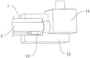
图4为本发明一种单孔机器人用智能可暴露吸引器的外管后端处剖视图;4 is a cross-sectional view of the rear end of an outer tube of an intelligent exposeable suction device for a single-hole robot according to the present invention;
图5为本发明一种单孔机器人用智能可暴露吸引器的驱动机构处剖视图。FIG. 5 is a cross-sectional view of the driving mechanism of an intelligent exposeable attractor for a single-hole robot according to the present invention.
1、外管;2、内管;3、爪;4、凹槽;5、转轴;6、第一伸缩缸;7、滑块;8、滑杆;9、T型槽;10、转动套;11、铁丝;12、铰链;13、第二伸缩缸;14、抽吸泵;15、固定块;16、蓄电池;17、控制开关;18、握把。1. Outer tube; 2. Inner tube; 3. Claw; 4. Groove; 5. Rotating shaft; 6. First telescopic cylinder; 7. Slider; 8. Slider; 9. T-slot; 10. Rotating sleeve ; 11, iron wire; 12, hinge; 13, second telescopic cylinder; 14, suction pump; 15, fixed block; 16, battery; 17, control switch; 18, handle.
具体实施方式Detailed ways
以下描述用于揭露本发明以使本领域技术人员能够实现本发明。以下描述中的优选实施例只作为举例,本领域技术人员可以想到其他显而易见的变型。The following description serves to disclose the invention to enable those skilled in the art to practice the invention. The preferred embodiments described below are given by way of example only, and other obvious modifications will occur to those skilled in the art.
如图1-图5所示的一种单孔机器人用智能可暴露吸引器,包括外管1,外管1的内侧插装有内管2,内管2前端延伸至外管1的前方,外管1的前端处设置有驱使内管2拐弯的转动机构,外管1的前端端口转动连接有若干个爪3,若干个爪3通过设置在后端的驱动机构来使其前端相互靠近或者相互远离,内管2朝向后方延伸并在后端端口处设置抽吸部。As shown in Fig. 1-Fig. 5, an intelligent exposable suction device for a single-hole robot includes an
内管2软质橡胶材质,保障前端可以被弯曲角度,外管1为塑料材质,转动机构包括固定套装在内管2外表面靠近前端的转动套10,转动套10的下端通过铰链12转动连接有铁丝11,铁丝11滑动穿过外管1的内部且后端处连接第二伸缩缸13,第二伸缩缸13固定嵌入在外管1的内部靠近后端处。The
驱动机构包括开设在外管1端口的凹槽4,爪3的后端边沿上通过转轴5与凹槽4内壁转动配合,凹槽4底面设置有顶动机构,顶动机构包括固定嵌入安装在凹槽4内壁的第一伸缩缸6,第一伸缩缸6的伸缩端固定连接有滑块7,滑块7的两侧延伸出滑杆8,爪3的外表面开设有T型槽9,滑块7与滑杆8滑动卡入T型槽9的内侧,可以灵活控制若干个爪3的前端相互靠近或者远离。The driving mechanism includes a
抽吸时,可以在内管2的后端处进行吸引,为方便使用,抽吸部包括固定连接在外管1后端的固定块15,内管2穿过固定块15的内侧且端口连接抽吸泵14的抽吸端,抽吸泵14嵌入安装固定块15的内侧,抽吸泵14的排出端位于固定块15的外侧,通过控制抽吸泵14工作,即可进行抽吸,采用电控方式较为便利。During suction, suction can be performed at the rear end of the
固定块15的下端固定连接有握把18,握把18的外表面嵌入安装有控制开关17与蓄电池16,显然的,控制开关17与蓄电池16电性连接,再将控制开关17与抽吸泵14、第一伸缩缸6与第二伸缩缸13电性连接,实现电控,为抽吸过程带来便利。The lower end of the
使用时,外管1的前端接触抽吸位置时,通过控制第一伸缩缸6伸长,使得滑块7与滑杆8上移,从而使得爪3被顶动,T型槽9保障了滑块7与滑杆8可以相对的在内侧滑动,避免发生卡死问题,进而使得若干的爪3的前端相互远离,即起到了拨开脂肪的目的,因为内脏里面空隙很小,撑开后形成空间,积液就会汇聚在形成空间内,之后将内管2前端对准空间中的积液进行抽吸,通过第二伸缩缸13伸缩,拉拽或者推动铁丝11,在铰链12的配合下,进而使得转动套10转动,从而将内管2的前端角度改变,以适应伸入进行抽吸,通过控制抽吸泵14工作,使得内管2前端对积液进行抽吸,较为便利,可以灵活运用在腹腔通道狭小空间内,方便调节吸引的角度,不会受到周围内脏脂肪的阻碍,带来便利。When in use, when the front end of the
以上显示和描述了本发明的基本原理、主要特征和本发明的优点。本行业的技术人员应该了解,本发明不受上述实施例的限制,上述实施例和说明书中描述的只是本发明的原理,在不脱离本发明精神和范围的前提下本发明还会有各种变化和改进,这些变化和改进都落入要求保护的本发明的范围内。本发明要求的保护范围由所附的权利要求书及其等同物界定。The foregoing has shown and described the basic principles, main features and advantages of the present invention. It should be understood by those skilled in the art that the present invention is not limited by the above-mentioned embodiments. The above-mentioned embodiments and descriptions describe only the principles of the present invention. Without departing from the spirit and scope of the present invention, there are various Variations and improvements are intended to fall within the scope of the claimed invention. The scope of protection claimed by the present invention is defined by the appended claims and their equivalents.
Claims (7)
Translated fromChinesePriority Applications (1)
| Application Number | Priority Date | Filing Date | Title |
|---|---|---|---|
| CN202210064027.1ACN114404682A (en) | 2022-01-20 | 2022-01-20 | Intelligent exposable aspirator for single-hole robot |
Applications Claiming Priority (1)
| Application Number | Priority Date | Filing Date | Title |
|---|---|---|---|
| CN202210064027.1ACN114404682A (en) | 2022-01-20 | 2022-01-20 | Intelligent exposable aspirator for single-hole robot |
Publications (1)
| Publication Number | Publication Date |
|---|---|
| CN114404682Atrue CN114404682A (en) | 2022-04-29 |
Family
ID=81274749
Family Applications (1)
| Application Number | Title | Priority Date | Filing Date |
|---|---|---|---|
| CN202210064027.1APendingCN114404682A (en) | 2022-01-20 | 2022-01-20 | Intelligent exposable aspirator for single-hole robot |
Country Status (1)
| Country | Link |
|---|---|
| CN (1) | CN114404682A (en) |
Citations (7)
| Publication number | Priority date | Publication date | Assignee | Title |
|---|---|---|---|---|
| US20070135686A1 (en)* | 2005-12-14 | 2007-06-14 | Pruitt John C Jr | Tools and methods for epicardial access |
| CN107206204A (en)* | 2014-12-01 | 2017-09-26 | 皇家飞利浦有限公司 | Conduit is turned to for the flexibly prebuckling with traction fiber of deflection control |
| CN214969721U (en)* | 2021-02-02 | 2021-12-03 | 广西医科大学 | tissue exposure aspirator |
| CN214966315U (en)* | 2021-04-07 | 2021-12-03 | 四川大学华西医院 | A thoracoscopic surgical suction device |
| CN214969701U (en)* | 2021-01-22 | 2021-12-03 | 袁巍 | Novel aspirator used in medical operation |
| CN215306439U (en)* | 2021-06-10 | 2021-12-28 | 天津市泌尿外科研究所 | Laparoscopic surgery is with supplementary pincers with attract function |
| CN215384432U (en)* | 2021-07-28 | 2022-01-04 | 河南省人民医院 | Flushable suction stripping knife for brain tumor resection |
- 2022
- 2022-01-20CNCN202210064027.1Apatent/CN114404682A/enactivePending
Patent Citations (7)
| Publication number | Priority date | Publication date | Assignee | Title |
|---|---|---|---|---|
| US20070135686A1 (en)* | 2005-12-14 | 2007-06-14 | Pruitt John C Jr | Tools and methods for epicardial access |
| CN107206204A (en)* | 2014-12-01 | 2017-09-26 | 皇家飞利浦有限公司 | Conduit is turned to for the flexibly prebuckling with traction fiber of deflection control |
| CN214969701U (en)* | 2021-01-22 | 2021-12-03 | 袁巍 | Novel aspirator used in medical operation |
| CN214969721U (en)* | 2021-02-02 | 2021-12-03 | 广西医科大学 | tissue exposure aspirator |
| CN214966315U (en)* | 2021-04-07 | 2021-12-03 | 四川大学华西医院 | A thoracoscopic surgical suction device |
| CN215306439U (en)* | 2021-06-10 | 2021-12-28 | 天津市泌尿外科研究所 | Laparoscopic surgery is with supplementary pincers with attract function |
| CN215384432U (en)* | 2021-07-28 | 2022-01-04 | 河南省人民医院 | Flushable suction stripping knife for brain tumor resection |
Non-Patent Citations (1)
| Title |
|---|
| 陈丁跃: "《现代汽车设计制造工艺》", 28 February 2015, 西安交通大学出版社, pages: 162 - 163* |
Similar Documents
| Publication | Publication Date | Title |
|---|---|---|
| CN108420506B (en) | But washing attracts and quick replacement catheter's abdominal cavity pincers | |
| CN114404682A (en) | Intelligent exposable aspirator for single-hole robot | |
| CN210903226U (en) | Blood clot triturating and cleaning device under endoscope | |
| CN210784611U (en) | Disposable uterine cavity tissue suction tube | |
| CN108187156A (en) | Suction device in intervertenral space under Percutaneous endoscopic | |
| CN208709985U (en) | Urology Surgery foreign matter clamping device | |
| CN113349885B (en) | Endoscopic surgery forceps with suction function | |
| CN110840520A (en) | A device for removing stones in hepatobiliary surgery | |
| CN216365185U (en) | Novel enteroscope that can release and retrieve is with intestines and stomach blocking pincers | |
| CN214761347U (en) | A device based on anal fistula wall tissue curettage | |
| CN211751364U (en) | A medical spiral suction device | |
| CN108668629B (en) | A strawberry picking device | |
| CN104069560A (en) | Aspirator capable of being adjusted under endoscope | |
| CN220632752U (en) | An intubation pusher | |
| CN221557017U (en) | Uterine cavity suction tube | |
| CN220175688U (en) | Aspirator for orthopedic operation | |
| CN220938661U (en) | A suction device for laparoscopic surgery | |
| CN217430271U (en) | A tool for adjusting the gastrointestinal stent for digestive endoscopy | |
| CN222998089U (en) | A portable multi-stage adjustment sputum suction device | |
| CN215228827U (en) | Filter recovery device | |
| CN215018530U (en) | Adjustable exhaust separation forceps for laparoscope | |
| CN218922722U (en) | Intraoperative urinary calculus grabber | |
| CN215194163U (en) | Use under thoracoscope and prevent blockking up aspirator | |
| CN211325374U (en) | A kind of urology gravel removal device | |
| CN117122260B (en) | Laparoscope equipment convenient for keeping clear view |
Legal Events
| Date | Code | Title | Description |
|---|---|---|---|
| PB01 | Publication | ||
| PB01 | Publication | ||
| SE01 | Entry into force of request for substantive examination | ||
| SE01 | Entry into force of request for substantive examination | ||
| RJ01 | Rejection of invention patent application after publication | ||
| RJ01 | Rejection of invention patent application after publication | Application publication date:20220429 |