CN114401606B - Electromagnetic shielding device for electronic equipment - Google Patents
Electromagnetic shielding device for electronic equipmentDownload PDFInfo
- Publication number
- CN114401606B CN114401606BCN202210299566.3ACN202210299566ACN114401606BCN 114401606 BCN114401606 BCN 114401606BCN 202210299566 ACN202210299566 ACN 202210299566ACN 114401606 BCN114401606 BCN 114401606B
- Authority
- CN
- China
- Prior art keywords
- wall
- fixedly connected
- plate
- electromagnetic shielding
- supporting plate
- Prior art date
- Legal status (The legal status is an assumption and is not a legal conclusion. Google has not performed a legal analysis and makes no representation as to the accuracy of the status listed.)
- Active
Links
- 230000001681protective effectEffects0.000claimsdescription38
- 238000004140cleaningMethods0.000claimsdescription15
- 230000017525heat dissipationEffects0.000claimsdescription8
- 230000007246mechanismEffects0.000claimsdescription8
- 238000005096rolling processMethods0.000claims1
- 230000000694effectsEffects0.000abstractdescription17
- 230000009471actionEffects0.000abstractdescription9
- 238000004891communicationMethods0.000abstractdescription6
- 230000005540biological transmissionEffects0.000abstractdescription4
- 238000013461designMethods0.000abstractdescription3
- 238000009434installationMethods0.000description19
- 238000010586diagramMethods0.000description10
- 238000001816coolingMethods0.000description7
- 238000000034methodMethods0.000description4
- 238000001179sorption measurementMethods0.000description4
- 230000009286beneficial effectEffects0.000description3
- 230000008569processEffects0.000description3
- 239000000428dustSubstances0.000description2
- 230000006872improvementEffects0.000description2
- 238000007664blowingMethods0.000description1
- 230000005670electromagnetic radiationEffects0.000description1
- 238000002474experimental methodMethods0.000description1
- 238000000605extractionMethods0.000description1
- 238000012423maintenanceMethods0.000description1
- 238000012986modificationMethods0.000description1
- 230000004048modificationEffects0.000description1
- 230000002093peripheral effectEffects0.000description1
- 238000005086pumpingMethods0.000description1
- 238000000926separation methodMethods0.000description1
Images


Classifications
- H—ELECTRICITY
- H05—ELECTRIC TECHNIQUES NOT OTHERWISE PROVIDED FOR
- H05K—PRINTED CIRCUITS; CASINGS OR CONSTRUCTIONAL DETAILS OF ELECTRIC APPARATUS; MANUFACTURE OF ASSEMBLAGES OF ELECTRICAL COMPONENTS
- H05K5/00—Casings, cabinets or drawers for electric apparatus
- H05K5/02—Details
- H05K5/0217—Mechanical details of casings
- H—ELECTRICITY
- H04—ELECTRIC COMMUNICATION TECHNIQUE
- H04K—SECRET COMMUNICATION; JAMMING OF COMMUNICATION
- H04K3/00—Jamming of communication; Counter-measures
- H—ELECTRICITY
- H05—ELECTRIC TECHNIQUES NOT OTHERWISE PROVIDED FOR
- H05K—PRINTED CIRCUITS; CASINGS OR CONSTRUCTIONAL DETAILS OF ELECTRIC APPARATUS; MANUFACTURE OF ASSEMBLAGES OF ELECTRICAL COMPONENTS
- H05K5/00—Casings, cabinets or drawers for electric apparatus
- H05K5/02—Details
- H05K5/0213—Venting apertures; Constructional details thereof
- H—ELECTRICITY
- H05—ELECTRIC TECHNIQUES NOT OTHERWISE PROVIDED FOR
- H05K—PRINTED CIRCUITS; CASINGS OR CONSTRUCTIONAL DETAILS OF ELECTRIC APPARATUS; MANUFACTURE OF ASSEMBLAGES OF ELECTRICAL COMPONENTS
- H05K5/00—Casings, cabinets or drawers for electric apparatus
- H05K5/10—Casings, cabinets or drawers for electric apparatus comprising several parts forming a closed casing
- H—ELECTRICITY
- H05—ELECTRIC TECHNIQUES NOT OTHERWISE PROVIDED FOR
- H05K—PRINTED CIRCUITS; CASINGS OR CONSTRUCTIONAL DETAILS OF ELECTRIC APPARATUS; MANUFACTURE OF ASSEMBLAGES OF ELECTRICAL COMPONENTS
- H05K7/00—Constructional details common to different types of electric apparatus
- H05K7/20—Modifications to facilitate cooling, ventilating, or heating
- H05K7/20009—Modifications to facilitate cooling, ventilating, or heating using a gaseous coolant in electronic enclosures
- H05K7/20136—Forced ventilation, e.g. by fans
- H05K7/20145—Means for directing air flow, e.g. ducts, deflectors, plenum or guides
- H—ELECTRICITY
- H05—ELECTRIC TECHNIQUES NOT OTHERWISE PROVIDED FOR
- H05K—PRINTED CIRCUITS; CASINGS OR CONSTRUCTIONAL DETAILS OF ELECTRIC APPARATUS; MANUFACTURE OF ASSEMBLAGES OF ELECTRICAL COMPONENTS
- H05K7/00—Constructional details common to different types of electric apparatus
- H05K7/20—Modifications to facilitate cooling, ventilating, or heating
- H05K7/20009—Modifications to facilitate cooling, ventilating, or heating using a gaseous coolant in electronic enclosures
- H05K7/20136—Forced ventilation, e.g. by fans
- H05K7/20181—Filters; Louvers
- Y—GENERAL TAGGING OF NEW TECHNOLOGICAL DEVELOPMENTS; GENERAL TAGGING OF CROSS-SECTIONAL TECHNOLOGIES SPANNING OVER SEVERAL SECTIONS OF THE IPC; TECHNICAL SUBJECTS COVERED BY FORMER USPC CROSS-REFERENCE ART COLLECTIONS [XRACs] AND DIGESTS
- Y02—TECHNOLOGIES OR APPLICATIONS FOR MITIGATION OR ADAPTATION AGAINST CLIMATE CHANGE
- Y02A—TECHNOLOGIES FOR ADAPTATION TO CLIMATE CHANGE
- Y02A30/00—Adapting or protecting infrastructure or their operation
Landscapes
- Engineering & Computer Science (AREA)
- Microelectronics & Electronic Packaging (AREA)
- Physics & Mathematics (AREA)
- Thermal Sciences (AREA)
- Computer Networks & Wireless Communication (AREA)
- Signal Processing (AREA)
- Cooling Or The Like Of Electrical Apparatus (AREA)
- Shielding Devices Or Components To Electric Or Magnetic Fields (AREA)
Abstract
Translated fromChinese
Description
Translated fromChinese技术领域technical field
本发明涉及电子通信设备屏蔽技术领域,尤其是涉及一种电子设备电磁屏蔽装置。The invention relates to the technical field of shielding of electronic communication equipment, in particular to an electromagnetic shielding device for electronic equipment.
背景技术Background technique
在未来信息化战争中战场电磁环境将极为复杂,如果不能采取相应的电磁屏蔽措施,势必导致相关指挥通信的电子设备性能下降,从而影响作战进程甚至战争成败。众所周知,任何电子设备都要在一定的电磁环境下才能正常工作,实验证明,在电磁辐射超过其阈值时,该电子设备将失去功能。战时,各种电子设备将处于十分恶劣的电磁环境中,一旦其电磁屏蔽条件受到破坏,就将面临严重后果。In the future information warfare, the battlefield electromagnetic environment will be extremely complex. If the corresponding electromagnetic shielding measures cannot be taken, the performance of the electronic equipment related to command and communication will be degraded, thus affecting the combat process and even the success or failure of the war. As we all know, any electronic device can work normally only in a certain electromagnetic environment. Experiments have shown that when the electromagnetic radiation exceeds its threshold, the electronic device will lose its function. In wartime, all kinds of electronic equipment will be in a very harsh electromagnetic environment, and once its electromagnetic shielding conditions are damaged, it will face serious consequences.
公开号为CN209643272U的中国实用新型专利,公开了一种电子产品通信设备电磁屏蔽装置,包括支撑板,所述支撑板的两侧均活动套接有定位杆,所述定位杆的顶端固定连接有保护罩,所述保护罩的底部与支撑板的顶部接触,所述支撑板顶部的右侧固定连接有定位轴,所述定位轴的外表面活动套接有长条板,所述长条板的侧面固定连接有屏蔽仪本体,所述支撑板上开设有限位槽。上述电子产品通信设备电磁屏蔽装置,通过驱动马达和驱动杆的配合下,进而带动限位弹簧和拨动杆转动,进一步对屏蔽仪本体进行拨动,加上在回复弹簧的配合下,同时利用回复弹簧的回复性,使得屏蔽仪本体进行往复旋转,从而达到了动态全方位屏蔽信号的效果。The Chinese utility model patent with publication number CN209643272U discloses an electromagnetic shielding device for electronic product communication equipment, including a support plate, two sides of the support plate are movably sleeved with positioning rods, and the top of the positioning rod is fixedly connected with a a protective cover, the bottom of the protective cover is in contact with the top of the support plate, the right side of the top of the support plate is fixedly connected with a positioning shaft, the outer surface of the positioning shaft is movably sleeved with a long strip, the long strip The side of the shielding device is fixedly connected with the shielding instrument body, and the support plate is provided with a limit slot. The above-mentioned electromagnetic shielding device for communication equipment of electronic products, through the cooperation of the driving motor and the driving rod, further drives the limit spring and the toggle rod to rotate, and further toggles the shielding device body. The resilience of the return spring makes the shielding instrument body rotate back and forth, thus achieving the effect of dynamic omnidirectional shielding of signals.
但是上述发明存在以下不足之处:上述专利复位时利用弹簧的特性,导致实际使用时容易产生余震、抖动,影响屏蔽装置信号的稳定性;上述专利并未对转动过程进行更进一步利用,其仅仅利用通口进行散热,散热缓慢、降温效果不明显,故而存在局限性。However, the above-mentioned invention has the following shortcomings: the above-mentioned patent uses the characteristics of the spring when resetting, which leads to aftershocks and jitters in actual use, which affects the stability of the signal of the shielding device; the above-mentioned patent does not make further use of the rotation process, but only Using the port for heat dissipation, the heat dissipation is slow and the cooling effect is not obvious, so there are limitations.
发明内容SUMMARY OF THE INVENTION
本发明的目的在于提供一种电子设备电磁屏蔽装置,以解决上述背景技术中提出的问题。The purpose of the present invention is to provide an electromagnetic shielding device for electronic equipment to solve the above-mentioned problems in the background art.
本发明的技术方案是:一种电子设备电磁屏蔽装置,包括安装底板和托板,所述安装底板和托板之间安装有防护组件,所述托板的上方设置有装置主壳体,且装置主壳体上固定连接有电磁屏蔽器主体,所述装置主壳体的底部外壁中心处固定连接有转柱,且转柱与托板通过轴承转动连接,所述托板与安装底板之间固定连接有底端筒,所述底端筒靠近安装底板的一端开设有多个均匀分布的滤孔,且底端筒与转柱之间安装有摆动组件,所述摆动组件包括固定安装于转柱底部外壁上的齿轮,且底端筒的圆周内壁一侧固定安装有水平设置的往复推杆电机,所述往复推杆电机的延伸杆端部固定连接有齿条,且转柱的底部外壁固定安装有与齿条相啮合的齿轮,所述底端筒的圆周内壁另一端固定安装有水平设置的腔筒,且腔筒的一端外壁分别固定连接有出气管以及进气管,所述进气管和出气管的一端外壁分别固定连接有单向阀一和单向阀二,所述齿条远离往复推杆电机的一端外壁固定安装有活塞板,且活塞板与腔筒的内壁形成滑动配合,所述托板内部开设有与出气管相连通的环形腔道,且托板的顶部外壁开设有多个与环形腔道相连通的出气孔,所述装置主壳体的底端开设有多个等距离分布的进气口,且进气口和出气孔的剖面均呈上窄下宽的梯形结构,所述装置主壳体的一端圆周外壁上开设有多个均匀分布的散热孔。The technical solution of the present invention is: an electromagnetic shielding device for electronic equipment, comprising a mounting base plate and a support plate, a protection component is installed between the mounting base plate and the support plate, a device main casing is arranged above the support plate, and The main body of the device is fixedly connected with the main body of the electromagnetic shielding device, the center of the bottom outer wall of the main body of the device is fixedly connected with a rotating column, and the rotating column and the supporting plate are rotatably connected by bearings, and the supporting plate and the installation bottom plate are rotatably connected. A bottom end cylinder is fixedly connected, the end of the bottom end cylinder close to the installation bottom plate is provided with a plurality of evenly distributed filter holes, and a swing assembly is installed between the bottom end cylinder and the rotating column. A gear on the outer wall of the column bottom, and a horizontally arranged reciprocating push rod motor is fixedly installed on one side of the inner circumferential wall of the bottom end cylinder, the end of the extension rod of the reciprocating push rod motor is fixedly connected with a rack, and the bottom outer wall of the rotating column A gear meshing with the rack is fixedly installed, the other end of the inner circumferential wall of the bottom end cylinder is fixedly installed with a horizontally arranged cavity cylinder, and the outer wall of one end of the cavity cylinder is fixedly connected with an air outlet pipe and an air intake pipe, respectively. A one-way valve and a second one-way valve are respectively fixedly connected to the outer wall of one end of the air outlet pipe. A piston plate is fixedly installed on the outer wall of one end of the rack away from the reciprocating push rod motor, and the piston plate forms a sliding fit with the inner wall of the cavity cylinder. The inside of the support plate is provided with an annular cavity that communicates with the air outlet pipe, the top outer wall of the support plate is provided with a plurality of air outlet holes that communicate with the annular cavity, and the bottom end of the main casing of the device is provided with a plurality of air holes. The air inlets are equidistantly distributed, and the cross-sections of the air inlets and the air outlet holes are trapezoidal structures with a narrow upper and a wider lower, and a plurality of uniformly distributed heat dissipation holes are opened on the peripheral outer wall of one end of the main casing of the device.
优选的,所述防护组件包括四个固定安装于安装底板顶部外壁拐角处的托杆,且相互靠近的两个托杆上转动连接有轴杆,两个所述轴杆的圆周外壁一侧均固定安装有防护罩,且两个防护罩分别位于托板的两侧。Preferably, the protection assembly includes four support rods fixedly installed at the corners of the outer wall of the top of the installation base plate, and two support rods close to each other are rotatably connected with shaft rods, and one side of the circumferential outer wall of the two shaft rods is on one side. A protective cover is fixedly installed, and the two protective covers are respectively located on both sides of the support plate.
优选的,两个所述防护罩的一侧内壁均固定安装有连接块,且连接块与托板之间均通过铰链连接有电动伸缩杆,两个所述防护罩相互靠近的一侧外壁均固定安装有橡胶条,且两个橡胶条均设置有相匹配的波状咬合端。Preferably, a connecting block is fixedly installed on one inner wall of the two protective covers, and an electric telescopic rod is connected between the connecting block and the supporting plate through a hinge, and the two outer walls of the two protective covers are close to each other. Rubber strips are fixedly installed, and both rubber strips are provided with matching undulating occlusal ends.
优选的,所述底端筒的内部设置有用于清洁滤孔的清洁机构。Preferably, a cleaning mechanism for cleaning the filter holes is provided inside the bottom end cylinder.
优选的,所述清洁机构包括固定安装于齿轮底部外壁的延伸柱,且延伸柱的外壁上套设有套筒,所述套筒的圆周外壁两侧均固定安装有水平设置的侧轴,且两个侧轴的端部均固定连接有刷块,所述刷块上设置有与滤孔相接触的刷毛。Preferably, the cleaning mechanism includes an extension column fixedly installed on the outer wall of the bottom of the gear, and a sleeve is sleeved on the outer wall of the extension column, and horizontally arranged side shafts are fixedly installed on both sides of the circumferential outer wall of the sleeve, and The ends of the two side shafts are fixedly connected with brush blocks, and the brush blocks are provided with bristles in contact with the filter holes.
优选的,所述延伸柱的一侧开设有收纳口,且收纳口的一侧内壁固定安装有电磁条,收纳口的内壁两端均固定安装有拉伸弹簧,且拉伸弹簧的端部固定连接有磁条,所述磁条与电磁条的磁极方向相反,且套筒圆周内壁开设有与磁条在竖直方向上滑动配合的槽口。Preferably, a receiving port is opened on one side of the extension column, an electromagnetic strip is fixedly installed on the inner wall of one side of the receiving port, tension springs are fixedly installed on both ends of the inner wall of the receiving port, and the ends of the tension springs are fixed A magnetic strip is connected, and the magnetic pole direction of the magnetic strip is opposite to that of the electromagnetic strip, and the inner wall of the circumference of the sleeve is provided with a notch which is slidably matched with the magnetic strip in the vertical direction.
优选的,所述齿轮底部外壁固定连接有复位弹簧,且复位弹簧底端与套筒顶端相接触,所述套筒的底端开设有斜剖面,且安装底板的顶部外壁固定安装有与斜剖面靠近边缘处相对应的球头抵杆。Preferably, a return spring is fixedly connected to the outer wall of the bottom of the gear, and the bottom end of the return spring is in contact with the top end of the sleeve. Corresponding ball butt bar near the edge.
优选的,所述安装底板的底部外壁四角均固定安装有吸盘,且安装底板的底部外壁固定安装有多个防滑框条,多个所述防滑框条的对角线位置相同。Preferably, suction cups are fixedly installed on the four corners of the bottom outer wall of the installation base plate, and a plurality of anti-skid frame strips are fixedly installed on the bottom outer wall of the installation base plate, and the diagonal positions of the plurality of anti-skid frame strips are the same.
优选的,所述装置主壳体底部外壁与托板的顶部外壁上均开设有规格相同的环形沉槽,且两个环形沉槽的内壁滚动连接有多个滚珠。Preferably, the outer wall of the bottom of the main casing of the device and the outer wall of the top of the support plate are provided with annular recesses of the same size, and the inner walls of the two annular recesses are rollingly connected with a plurality of balls.
优选的,所述进气口为每三个一组,且每组所述进气口呈环形阵列分布,所述单向阀一气体流出方向朝向腔筒的内部,且单向阀二的气体流出方向朝向环形腔道。Preferably, the air inlets are in groups of three, and each group of the air inlets is distributed in an annular array, the gas outflow direction of the one-way valve is toward the interior of the cavity, and the gas of the one-way valve two is The outflow direction is toward the annular channel.
本发明通过改进在此提供电子通信设备电磁屏蔽装置,与现有技术相比,具有如下改进及优点:The present invention provides an electromagnetic shielding device for electronic communication equipment through improvement, which has the following improvements and advantages compared with the prior art:
其一:本发明利用设置的摆动组件,在实际操作过程中,可通过往复推杆电机的运行,带动齿条在水平方向上来回移动,并经过齿条与齿轮的传动作用,可带动转柱以及安装有电磁屏蔽器主体的装置主壳体,来回往复摆动,最终形成扇形区域,在该区域中可有效防护外界的电磁干扰,相较于传统固定式装置,该设计能够有效减少电磁屏蔽的薄弱点,以确保对整个区域全方位的屏蔽效果。First: the present invention utilizes the set swing assembly. During the actual operation, the rack can be driven to move back and forth in the horizontal direction by the operation of the reciprocating push rod motor, and the rotating column can be driven by the transmission action of the rack and the gear. And the main casing of the device installed with the main body of the electromagnetic shield, swings back and forth, and finally forms a fan-shaped area, which can effectively protect the electromagnetic interference from the outside world. Compared with the traditional fixed device, this design can effectively reduce the electromagnetic shielding effect. Weak point to ensure full shielding effect on the entire area.
其二:本发明利用设置的腔筒,当齿条向腔筒方向移动时,能够推动活塞板,从而压缩腔筒内部体积,并将空气通过出气管鼓向环形腔道,并再经过出气孔鼓入进气口中,从而使装置主壳体内部形成气流,并使热量通过位于侧面的散热孔散出,以达到降温的目的;当齿条向往复推杆电机方向移动时,齿条拉动活塞板,此时,腔筒内部处于负压状态,外界空气依次经过滤孔、进气管以及单向阀一进入腔筒内部,从而方便持续对装置主壳体内部进行降温;利用将进气口和出气孔的剖面均设置呈上窄下宽的梯形结构,空气在流经时,能够形成狭管效应,从而有利于提高空气流动速率,能够针对性将装置主壳体内部的热量快速鼓出;以实现对驱动过程的深入利用,有利于增加驱动动作的作用效果;Second: the present invention utilizes the set cavity cylinder, when the rack moves in the direction of the cavity cylinder, it can push the piston plate, thereby compressing the inner volume of the cavity cylinder, and bulging the air to the annular cavity through the air outlet pipe, and then passing through the air outlet hole. Blow into the air inlet to form an air flow inside the main casing of the device and dissipate the heat through the heat dissipation holes located on the side to achieve the purpose of cooling; when the rack moves in the direction of the reciprocating push rod motor, the rack pulls the piston At this time, the inside of the cavity is in a negative pressure state, and the outside air enters the cavity through the filter hole, the air intake pipe and the one-way valve in turn, so as to facilitate the continuous cooling of the inside of the main shell of the device; The cross-section of the air outlet holes is set in a trapezoidal structure with a narrow upper and a lower width. When the air flows through, it can form a narrow tube effect, which is beneficial to improve the air flow rate and can quickly bulge out the heat inside the main casing of the device; In order to realize the in-depth utilization of the driving process, it is beneficial to increase the effect of the driving action;
其三:本发明利用设置的电动伸缩杆,当其延伸杆伸出时,可推动连接块,并使得防护罩分别以两个轴杆为圆心摆动,进而实现使两个防护罩相互远离,此时处于展开状态;同时,当两个防护罩展开时,防护罩与安装底板之间会拉开距离,从而方便将底端筒的滤孔暴露出来,以保证活塞板抽气作业的顺利进行;电动伸缩杆的延伸杆回抽时,两个防护罩相互闭合,此时处于收拢状态;当防护罩处于收拢状态时,两个波状咬合端相互咬合,有效提高两个橡胶条之间的接触面积,可提高防护罩的防护效果。Third: the present invention utilizes the provided electric telescopic rod. When the extension rod is extended, the connecting block can be pushed, and the protective cover can swing with the two shaft rods as the center of the circle, so as to realize the separation of the two protective covers from each other. At the same time, when the two protective covers are unfolded, the distance between the protective cover and the installation bottom plate will be widened, so that the filter hole of the bottom cylinder can be easily exposed, so as to ensure the smooth operation of the piston plate air extraction; When the extension rod of the electric telescopic rod is retracted, the two protective covers are closed with each other, and they are in a folded state; when the protective cover is in a folded state, the two corrugated bite ends bite each other, effectively increasing the contact area between the two rubber strips , which can improve the protective effect of the protective cover.
附图说明Description of drawings
为了更清楚地说明本发明具体实施方式或现有技术中的技术方案,下面将对具体实施方式或现有技术描述中所需要使用的附图作简单地介绍,显而易见地,下面描述中的附图是本发明的一些实施方式,对于本领域普通技术人员来讲,在不付出创造性劳动的前提下,还可以根据这些附图获得其他的附图。In order to illustrate the specific embodiments of the present invention or the technical solutions in the prior art more clearly, the following briefly introduces the accompanying drawings that need to be used in the description of the specific embodiments or the prior art. Obviously, the accompanying drawings in the following description The drawings are some embodiments of the present invention. For those of ordinary skill in the art, other drawings can also be obtained based on these drawings without creative efforts.
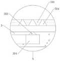
图1为本发明的整体剖视结构示意图;Fig. 1 is the overall sectional structure schematic diagram of the present invention;
图2为本发明的图1中A处放大结构示意图;Fig. 2 is the enlarged structural schematic diagram of A place in Fig. 1 of the present invention;
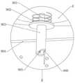
图3为本发明的整体第一视角立体结构示意图;3 is a schematic diagram of the overall first-view three-dimensional structure of the present invention;
图4为本发明的整体第二视角立体结构示意图;FIG. 4 is a schematic diagram of the overall second viewing angle three-dimensional structure of the present invention;
图5为本发明的防护罩展开状态结构示意图;5 is a schematic structural diagram of the protective cover of the present invention in an unfolded state;
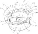
图6为本发明的底端筒半剖视立体结构示意图;6 is a schematic diagram of the half-sectioned perspective structure of the bottom end cylinder of the present invention;
图7为本发明的图6中B处放大结构示意图;Fig. 7 is the enlarged structural schematic diagram at B in Fig. 6 of the present invention;
图8为本发明的装置主壳体立体结构示意图;FIG. 8 is a schematic three-dimensional structure diagram of the main casing of the device of the present invention;
图9为本发明的底端筒剖视结构示意图;Fig. 9 is the sectional structure schematic diagram of the bottom end cylinder of the present invention;
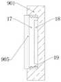
图10为本发明的延伸柱剖视结构示意图。FIG. 10 is a schematic cross-sectional structural diagram of the extension column of the present invention.
附图标记:Reference number:
1、安装底板;101、吸盘;102、防滑框条;103、托杆;104、轴杆;2、底端筒;201、滤孔;3、托板;301、电动伸缩杆;302、连接块;303、出气孔;304、环形腔道;4、防护罩;401、橡胶条;402、波状咬合端;5、电磁屏蔽器主体;501、装置主壳体;502、散热孔;503、环形沉槽;504、进气口;6、往复推杆电机;7、齿条;8、齿轮;9、清洁机构;901、延伸柱;902、复位弹簧;903、套筒;904、侧轴;905、磁条;906、球头抵杆;907、刷块;10、转柱;11、活塞板;12、腔筒;13、出气管;14、进气管;15、单向阀一;16、单向阀二;17、收纳口;18、电磁条;19、拉伸弹簧。1. Installation bottom plate; 101, suction cup; 102, anti-skid frame strip; 103, support rod; 104, shaft rod; 2, bottom cylinder; 201, filter hole; 3, support plate; 301, electric telescopic rod; 302, connection block; 303, air outlet; 304, annular cavity; 4, protective cover; 401, rubber strip; 402, corrugated bite end; 5, main body of electromagnetic shielding device; 501, main casing of device; 502, cooling hole; 503, Annular sink; 504, air inlet; 6, reciprocating push rod motor; 7, rack; 8, gear; 9, cleaning mechanism; 901, extension column; 902, return spring; 903, sleeve; 904, side shaft ; 905, magnetic strip; 906, ball end rod; 907, brush block; 10, rotating column; 11, piston plate; 12, cavity cylinder; 13, air outlet pipe; 14, air inlet pipe; 15, one-way valve; 16. One-way valve two; 17. Storage port; 18. Electromagnetic strip; 19. Tension spring.
具体实施方式Detailed ways
下面对本发明进行详细说明,对本发明实施例中的技术方案进行清楚、完整地描述,显然,所描述的实施例仅仅是本发明一部分实施例,而不是全部的实施例。基于本发明中的实施例,本领域普通技术人员在没有做出创造性劳动前提下所获得的所有其他实施例,都属于本发明保护的范围。The present invention will be described in detail below, and the technical solutions in the embodiments of the present invention will be described clearly and completely. Obviously, the described embodiments are only a part of the embodiments of the present invention, rather than all the embodiments. Based on the embodiments of the present invention, all other embodiments obtained by those of ordinary skill in the art without creative efforts shall fall within the protection scope of the present invention.
本发明通过改进在此提供一种电子设备电磁屏蔽装置,本发明的技术方案是:The present invention provides an electromagnetic shielding device for electronic equipment by improving, and the technical scheme of the present invention is:
如图1至图10所示,包括安装底板1和托板3,安装底板1和托板3之间安装有防护组件,托板3的上方设置有装置主壳体501,且装置主壳体501上固定连接有电磁屏蔽器主体5,装置主壳体501的底部外壁中心处固定连接有转柱10,且转柱10与托板3通过轴承转动连接,托板3与安装底板1之间固定连接有底端筒2,底端筒2靠近安装底板1的一端开设有多个均匀分布的滤孔201,且底端筒2与转柱10之间安装有摆动组件,摆动组件包括固定安装于转柱10底部外壁上的齿轮8,且底端筒2的圆周内壁一侧固定安装有水平设置的往复推杆电机6,往复推杆电机6的延伸杆端部固定连接有齿条7,且转柱10的底部外壁固定安装有与齿条7相啮合的齿轮8,底端筒2的圆周内壁另一端固定安装有水平设置的腔筒12,且腔筒12的一端外壁分别固定连接有出气管13以及进气管14,进气管14和出气管13的一端外壁分别固定连接有单向阀一15和单向阀二16,齿条7远离往复推杆电机6的一端外壁固定安装有活塞板11,且活塞板11与腔筒12的内壁形成滑动配合,托板3内部开设有与出气管13相连通的环形腔道304,且托板3的顶部外壁开设有多个与环形腔道304相连通的出气孔303,装置主壳体501的底端开设有多个等距离分布的进气口504,且进气口504和出气孔303的剖面均呈上窄下宽的梯形结构,装置主壳体501的一端圆周外壁上开设有多个均匀分布的散热孔502。As shown in FIG. 1 to FIG. 10 , it includes an
借由上述结构,利用设置的摆动组件,在实际使用时,可通过往复推杆电机6的运行,带动齿条7在水平方向上来回移动,并经过齿条7与齿轮8的传动作用,可带动转柱10以及安装有电磁屏蔽器主体5的装置主壳体501,来回往复摆动,最终形成扇形区域,在该区域中可有效防护外界的电磁干扰,相较于传统固定式装置,该设计能够有效减少电磁屏蔽的薄弱点,以确保对整个区域全方位的屏蔽效果;With the above structure, using the provided swing assembly, in actual use, the
利用设置的腔筒12,当齿条7向腔筒12方向移动时,能够推动活塞板11,从而压缩腔筒12内部体积,并将空气通过出气管13鼓向环形腔道304,并再经过出气孔303鼓入进气口504中,从而使装置主壳体501内部形成气流,并使热量通过位于侧面的散热孔502散出,以达到降温的目的;当齿条7向往复推杆电机6方向移动时,齿条7拉动活塞板11,此时,腔筒12内部处于负压状态,外界空气依次经过滤孔201、进气管14以及单向阀一15进入腔筒12内部,从而方便持续对装置主壳体501内部进行降温;利用将进气口504和出气孔303的剖面均设置呈上窄下宽的梯形结构,空气在流经时,能够形成狭管效应,从而有利于提高空气流动速率,保证将装置主壳体501的热量快速鼓出。With the provided
进一步的,防护组件包括四个固定安装于安装底板1顶部外壁拐角处的托杆103,且相互靠近的两个托杆103上转动连接有轴杆104,两个轴杆104的圆周外壁一侧均固定安装有防护罩4,且两个防护罩4分别位于托板3的两侧。Further, the protection assembly includes four
借由上述结构,利用设置的防护组件,能够利用两个防护罩4,在该装置不使用时,两个防护罩4处于闭合状态,从而能够对电磁屏蔽器主体5以及装置主壳体501起到良好的保护作用,避免其受到外力造成损伤,并能够起到良好的防尘效果。With the above structure, by using the provided protective assembly, two protective covers 4 can be used. When the device is not in use, the two protective covers 4 are in a closed state, so that the electromagnetic shielding device
进一步的,两个防护罩4的一侧内壁均固定安装有连接块302,且连接块302与托板3之间均通过铰链连接有电动伸缩杆301,两个防护罩4相互靠近的一侧外壁均固定安装有橡胶条401,且两个橡胶条401均设置有相匹配的波状咬合端402。Further, a connecting
借由上述结构,利用设置的电动伸缩杆301,当其延伸杆伸出时,可推动连接块302,并使得防护罩4分别以两个轴杆104为圆心摆动,进而实现使两个防护罩4相互远离,此时处于展开状态;同时,当两个防护罩4展开时,防护罩4与安装底板1之间会拉开距离,从而方便将底端筒2的滤孔201暴露出,以保证活塞板11抽气作业的顺利进行;电动伸缩杆301的延伸杆回抽时,两个防护罩4相互闭合,此时处于收拢状态;当防护罩4处于收拢状态时,两个波状咬合端402相互咬合,有效提高两个橡胶条401之间的接触面积,可提高防护罩4的防护效果。With the above structure, using the electric
进一步的,底端筒2的内部设置有用于清洁滤孔201的清洁机构9。Further, a
进一步的,清洁机构9包括固定安装于齿轮8底部外壁的延伸柱901,且延伸柱901的外壁上套设有套筒903,套筒903的圆周外壁两侧均固定安装有水平设置的侧轴904,且两个侧轴904的端部均固定连接有刷块907,刷块907上设置有与滤孔201相接触的刷毛。Further, the
借由上述结构,利用设置的清洁机构9,当齿轮8在齿条7驱动下摆动时,能够带动底端的延伸柱901转动。With the above structure, using the provided
进一步的,延伸柱901的一侧开设有收纳口17,且收纳口17的一侧内壁固定安装有电磁条18,收纳口17的内壁两端均固定安装有拉伸弹簧19,且拉伸弹簧19的端部固定连接有磁条905,磁条905与电磁条18的磁极方向相反,且套筒903圆周内壁开设有与磁条905在竖直方向上滑动配合的槽口。Further, one side of the
借由上述结构,需要对底端筒2进行清洁时,可控制启动电磁条18,利用磁条905与电磁条18的磁极方向相反产生排斥力,当延伸柱901转动至收纳口17与槽口相对齐时,磁条905在排斥力的作用下,卡入槽口内部,使得套筒903跟随延伸柱901转动,从而通过两侧的侧轴904带动刷块907转动扫过底端筒2的内壁,以达到清洁滤孔201的目的,可避免滤孔201被灰尘堵塞。With the above structure, when the
进一步的,齿轮8底部外壁固定连接有复位弹簧902,且复位弹簧902底端与套筒903顶端相接触,套筒903的底端开设有斜剖面,且安装底板1的顶部外壁固定安装有与斜剖面靠近边缘处相对应的球头抵杆906。Further, the bottom outer wall of the
借由上述结构,当套筒903转动时,在复位弹簧902的作用下,使斜剖面始终与球头抵杆906的顶端相接触,由于斜剖面与球头抵杆906的接触位置发生变化,能够使得套筒903在竖直方向上进行上下移动,从而可提高刷块907的作业范围,以达到提高清洁效果的目的。With the above structure, when the
进一步的,安装底板1的底部外壁四角均固定安装有吸盘101,且安装底板1的底部外壁固定安装有多个防滑框条102,多个防滑框条102的对角线位置相同。Further,
借由上述结构,利用设置的吸盘101方便对安装底板1进行吸附固定,同时,通过产生的吸附力,使得防滑框条102与接触面能够产生更大的压力,从而能够提高防滑效果,可进一步提高安装底板1放置时的稳定性。With the above structure, the installed
进一步的,装置主壳体501底部外壁与托板3的顶部外壁上均开设有规格相同的环形沉槽503,且两个环形沉槽503的内壁滚动连接有多个滚珠。Further, the bottom outer wall of the
借由上述结构,利用设置的环形沉槽503和滚珠,能够为装置主壳体501起到支撑、减阻作用。With the above structure, the annular recessed
进一步的,进气口504为每三个一组,且每组进气口504呈环形阵列分布,单向阀一15气体流出方向朝向腔筒12的内部,且单向阀二16的气体流出方向朝向环形腔道304。Further, the
借由上述结构,利用设置的单向阀一15和单向阀二16,能够对空气的流入、流出进行规划、控制,便于对装置主壳体501内部进行降温处理。With the above structure, the
本发明使用时,利用设置的吸盘101方便对安装底板1进行吸附固定,同时,通过产生的吸附力,使得防滑框条102与接触面产生更大的压力,从而提高防滑效果,进一步提高安装底板1放置时的稳定性;利用设置的电动伸缩杆301,当其延伸杆伸出时,可推动连接块302,并使得防护罩4分别以两个轴杆104为圆心摆动,进而实现使两个防护罩4相互远离,此时处于展开状态;同时,当两个防护罩4展开时,防护罩4与安装底板1之间会拉开距离,从而将底端筒2的滤孔201暴露出;在实际使用时,通过往复推杆电机6带动齿条7在水平方向上来回移动,经过齿条7与齿轮8的传动作用,带动转柱10以及安装有电磁屏蔽器主体5的装置主壳体501,来回往复摆动,最终形成扇形区域,在该区域中可有效防护外界的电磁干扰,相较于传统固定式装置,该设计能够有效减少电磁屏蔽的薄弱点,以确保对整个区域全方位的屏蔽效果;当齿条7向腔筒12方向移动时,推动活塞板11,从而压缩腔筒12内部体积,并将空气通过出气管13鼓向环形腔道304,并再经过出气孔303鼓入进气口504中,从而使装置主壳体501内部形成气流,并使热量通过位于侧面的散热孔502散出,以达到降温的目的;当齿条7向往复推杆电机6方向移动时,齿条7拉动活塞板11,此时,腔筒12内部处于负压状态,外界空气依次经过滤孔201、进气管14以及单向阀一15进入腔筒12内部,从而方便持续对装置主壳体501内部进行降温;利用将进气口504和出气孔303的剖面均设置呈上窄下宽的梯形结构,空气在流经时,形成狭管效应,从而有利于提高空气流动速率,保证将装置主壳体501的热量快速鼓出;当齿轮8在齿条7驱动下摆动时,带动底端的延伸柱901转动,需要对底端筒2进行清洁时,可控制启动电磁条18,利用磁条905与电磁条18的磁极方向相反产生排斥力,当延伸柱901转动至收纳口17与槽口相对齐时,磁条905在排斥力的作用下,卡入槽口内部,使得套筒903跟随延伸柱901转动,从而通过两侧的侧轴904带动刷块907转动扫过底端筒2的内壁,以达到清洁滤孔201的目的,避免滤孔201被灰尘堵塞;当套筒903转动时,在复位弹簧902的作用下,使斜剖面始终与球头抵杆906的顶端相接触,由于斜剖面与球头抵杆906的接触位置发生变化,使得套筒903在竖直方向上进行上下移动,从而提高刷块907的作业范围,以达到提高清洁效果的目的。When the present invention is used, the installed
上述说明,使本领域专业技术人员能够实现或使用本发明。对这些实施例的多种修改对本领域的专业技术人员来说将是显而易见的,本文中所定义的一般原理可以在不脱离本发明的精神或范围的情况下,在其它实施例中实现。因此,本发明将不会被限制于本文所示的这些实施例,而是要符合与本文所公开的原理和新颖特点相一致的最宽的范围。The above description enables those skilled in the art to implement or use the present invention. Various modifications to these embodiments will be readily apparent to those skilled in the art, and the generic principles defined herein may be implemented in other embodiments without departing from the spirit or scope of the invention. Thus, the present invention is not intended to be limited to the embodiments shown herein, but is to be accorded the widest scope consistent with the principles and novel features disclosed herein.
Claims (4)
Priority Applications (1)
| Application Number | Priority Date | Filing Date | Title |
|---|---|---|---|
| CN202210299566.3ACN114401606B (en) | 2022-03-25 | 2022-03-25 | Electromagnetic shielding device for electronic equipment |
Applications Claiming Priority (1)
| Application Number | Priority Date | Filing Date | Title |
|---|---|---|---|
| CN202210299566.3ACN114401606B (en) | 2022-03-25 | 2022-03-25 | Electromagnetic shielding device for electronic equipment |
Publications (2)
| Publication Number | Publication Date |
|---|---|
| CN114401606A CN114401606A (en) | 2022-04-26 |
| CN114401606Btrue CN114401606B (en) | 2022-06-07 |
Family
ID=81235039
Family Applications (1)
| Application Number | Title | Priority Date | Filing Date |
|---|---|---|---|
| CN202210299566.3AActiveCN114401606B (en) | 2022-03-25 | 2022-03-25 | Electromagnetic shielding device for electronic equipment |
Country Status (1)
| Country | Link |
|---|---|
| CN (1) | CN114401606B (en) |
Citations (1)
| Publication number | Priority date | Publication date | Assignee | Title |
|---|---|---|---|---|
| CN214102215U (en)* | 2021-01-31 | 2021-08-31 | 广东邦盛北斗技术服务有限公司 | Special storage device with electromagnetic shielding mechanism for electronic equipment |
Family Cites Families (7)
| Publication number | Priority date | Publication date | Assignee | Title |
|---|---|---|---|---|
| CN209376134U (en)* | 2018-11-10 | 2019-09-10 | 青岛空天电子信息技术研究院有限公司 | A kind of electromagnetic compatibility shielding device |
| CN209643272U (en)* | 2019-01-23 | 2019-11-15 | 长春职业技术学院 | A kind of electronic product communication equipment electromagnetic screen |
| CN111682840B (en)* | 2020-07-02 | 2021-06-15 | 杭州耀晗光伏设备有限公司 | Solar heat collecting device |
| CN214334290U (en)* | 2021-01-23 | 2021-10-01 | 山东蓝一检测技术有限公司 | A multi-functional sampling device for environmental monitoring |
| CN112979063B (en)* | 2021-02-05 | 2022-03-18 | 广州市水电建设工程有限公司 | Water environment ecological restoration device and using method thereof |
| CN113238085B (en)* | 2021-04-15 | 2023-09-29 | 国网山东省电力公司淄博供电公司 | Electric quantity and electric charge display device |
| CN113507062A (en)* | 2021-07-19 | 2021-10-15 | 李东明 | Outdoor lightning protection power distribution cabinet |
- 2022
- 2022-03-25CNCN202210299566.3Apatent/CN114401606B/enactiveActive
Patent Citations (1)
| Publication number | Priority date | Publication date | Assignee | Title |
|---|---|---|---|---|
| CN214102215U (en)* | 2021-01-31 | 2021-08-31 | 广东邦盛北斗技术服务有限公司 | Special storage device with electromagnetic shielding mechanism for electronic equipment |
Also Published As
| Publication number | Publication date |
|---|---|
| CN114401606A (en) | 2022-04-26 |
Similar Documents
| Publication | Publication Date | Title |
|---|---|---|
| CN216204966U (en) | Lithium battery drying device | |
| CN107515646B (en) | A new type of chassis with good dustproof effect | |
| CN107943238B (en) | Computer cabinet | |
| CN114401606B (en) | Electromagnetic shielding device for electronic equipment | |
| CN117712848A (en) | A dust removal distribution box and power supply control system for power grid regulation | |
| CN117460194A (en) | A waterproof and dustproof industrial control all-in-one machine for industrial workshops | |
| CN112312735A (en) | Server rack group that heat dissipation was removed dust | |
| CN211230871U (en) | Centrifugal vacuum pump machine case | |
| CN110427080B (en) | Computer cabinet | |
| CN217362742U (en) | Energy-saving three-phase asynchronous motor with higher protection capability | |
| CN220691873U (en) | Air circulation cooling pulse capacitor | |
| CN110932048B (en) | Hydraulic stretching type slot dust removal device for computer hardware | |
| CN211343098U (en) | An engine radiator with a dustproof device | |
| CN113377175A (en) | Big data server machine case dust collector | |
| CN210609955U (en) | Mobile precise electromechanical equipment with installation protection and noise reduction functions | |
| CN208780979U (en) | A kind of impact dedusting projection curtain device | |
| CN219865600U (en) | A cooling fan casing | |
| CN222147640U (en) | 4/5G dual-frenquency router convenient to clearance | |
| CN222185063U (en) | A compensating starting disk for air compressor | |
| CN214607119U (en) | Intelligent electric bicycle battery charging cabinet | |
| CN216790087U (en) | Imaging lamp with lens protection | |
| CN215257671U (en) | Avoid linear lead screw of deposition | |
| CN221149124U (en) | Projector with good heat dissipation effect | |
| CN216052576U (en) | Adjustable projector with heat dissipation guide structure | |
| CN221899505U (en) | A computer server that is easy to maintain |
Legal Events
| Date | Code | Title | Description |
|---|---|---|---|
| PB01 | Publication | ||
| PB01 | Publication | ||
| SE01 | Entry into force of request for substantive examination | ||
| SE01 | Entry into force of request for substantive examination | ||
| GR01 | Patent grant | ||
| GR01 | Patent grant |