CN114389035A - Antenna module - Google Patents
Antenna moduleDownload PDFInfo
- Publication number
- CN114389035A CN114389035ACN202111226624.1ACN202111226624ACN114389035ACN 114389035 ACN114389035 ACN 114389035ACN 202111226624 ACN202111226624 ACN 202111226624ACN 114389035 ACN114389035 ACN 114389035A
- Authority
- CN
- China
- Prior art keywords
- antenna
- ground plane
- extending direction
- module
- radiator
- Prior art date
- Legal status (The legal status is an assumption and is not a legal conclusion. Google has not performed a legal analysis and makes no representation as to the accuracy of the status listed.)
- Granted
Links
Images


Classifications
- H—ELECTRICITY
- H01—ELECTRIC ELEMENTS
- H01Q—ANTENNAS, i.e. RADIO AERIALS
- H01Q1/00—Details of, or arrangements associated with, antennas
- H01Q1/52—Means for reducing coupling between antennas; Means for reducing coupling between an antenna and another structure
- H01Q1/521—Means for reducing coupling between antennas; Means for reducing coupling between an antenna and another structure reducing the coupling between adjacent antennas
- H—ELECTRICITY
- H01—ELECTRIC ELEMENTS
- H01Q—ANTENNAS, i.e. RADIO AERIALS
- H01Q1/00—Details of, or arrangements associated with, antennas
- H01Q1/36—Structural form of radiating elements, e.g. cone, spiral, umbrella; Particular materials used therewith
- H—ELECTRICITY
- H01—ELECTRIC ELEMENTS
- H01Q—ANTENNAS, i.e. RADIO AERIALS
- H01Q1/00—Details of, or arrangements associated with, antennas
- H01Q1/48—Earthing means; Earth screens; Counterpoises
- H—ELECTRICITY
- H01—ELECTRIC ELEMENTS
- H01Q—ANTENNAS, i.e. RADIO AERIALS
- H01Q21/00—Antenna arrays or systems
- H01Q21/0006—Particular feeding systems
- H01Q21/0025—Modular arrays
- H—ELECTRICITY
- H01—ELECTRIC ELEMENTS
- H01Q—ANTENNAS, i.e. RADIO AERIALS
- H01Q5/00—Arrangements for simultaneous operation of antennas on two or more different wavebands, e.g. dual-band or multi-band arrangements
- H01Q5/30—Arrangements for providing operation on different wavebands
- H01Q5/307—Individual or coupled radiating elements, each element being fed in an unspecified way
- H01Q5/342—Individual or coupled radiating elements, each element being fed in an unspecified way for different propagation modes
- H01Q5/35—Individual or coupled radiating elements, each element being fed in an unspecified way for different propagation modes using two or more simultaneously fed points
- H—ELECTRICITY
- H01—ELECTRIC ELEMENTS
- H01Q—ANTENNAS, i.e. RADIO AERIALS
- H01Q7/00—Loop antennas with a substantially uniform current distribution around the loop and having a directional radiation pattern in a plane perpendicular to the plane of the loop
- H—ELECTRICITY
- H01—ELECTRIC ELEMENTS
- H01Q—ANTENNAS, i.e. RADIO AERIALS
- H01Q9/00—Electrically-short antennas having dimensions not more than twice the operating wavelength and consisting of conductive active radiating elements
- H01Q9/04—Resonant antennas
- H01Q9/0407—Substantially flat resonant element parallel to ground plane, e.g. patch antenna
- H01Q9/0421—Substantially flat resonant element parallel to ground plane, e.g. patch antenna with a shorting wall or a shorting pin at one end of the element
- H—ELECTRICITY
- H01—ELECTRIC ELEMENTS
- H01Q—ANTENNAS, i.e. RADIO AERIALS
- H01Q1/00—Details of, or arrangements associated with, antennas
- H01Q1/12—Supports; Mounting means
- H01Q1/22—Supports; Mounting means by structural association with other equipment or articles
- H01Q1/24—Supports; Mounting means by structural association with other equipment or articles with receiving set
- H01Q1/241—Supports; Mounting means by structural association with other equipment or articles with receiving set used in mobile communications, e.g. GSM
- H01Q1/242—Supports; Mounting means by structural association with other equipment or articles with receiving set used in mobile communications, e.g. GSM specially adapted for hand-held use
Landscapes
- Details Of Aerials (AREA)
- Variable-Direction Aerials And Aerial Arrays (AREA)
Abstract
Description
Translated fromChinese技术领域technical field
本发明涉及一种天线模块,且特别是涉及一种天线之间具有良好隔离度与天线效率的天线模块。The present invention relates to an antenna module, and in particular, to an antenna module with good isolation and antenna efficiency between antennas.
背景技术Background technique
第五代行动通信(5G)会有多支天线摆设在同一轴向上的需求,而要如何使这些天线之间具有良好的隔离度与天线效率,是本领域欲研究的目标。The fifth-generation mobile communication (5G) will require multiple antennas to be arranged on the same axis, and how to make these antennas have good isolation and antenna efficiency is the goal of research in this field.
发明内容SUMMARY OF THE INVENTION
本发明提供一种天线模块,其天线之间具有良好隔离度与天线效率。The present invention provides an antenna module with good isolation and antenna efficiency between the antennas.
本发明的一种天线模块,包括一第一天线、一第二天线、一第一接地面、一第三天线及一第二接地面。第一接地面位于第一天线及第二天线之间且连接于第一天线及第二天线,第一接地面具有靠近第一天线的一第一沟槽。第二天线位于第一天线及第三天线之间,第一天线的延伸方向不平行于第二天线的延伸方向,第二天线的延伸方向不平行于第三天线的延伸方向。第二接地面位于第二天线及第三天线之间且连接于第三天线,第二接地面与第二天线以及第一接地面分离设置,第二接地面具有一第二沟槽。An antenna module of the present invention includes a first antenna, a second antenna, a first ground plane, a third antenna and a second ground plane. The first ground plane is located between and connected to the first antenna and the second antenna, and the first ground plane has a first groove close to the first antenna. The second antenna is located between the first antenna and the third antenna, the extension direction of the first antenna is not parallel to the extension direction of the second antenna, and the extension direction of the second antenna is not parallel to the extension direction of the third antenna. The second ground plane is located between the second antenna and the third antenna and is connected to the third antenna, the second ground plane is separated from the second antenna and the first ground plane, and the second ground plane has a second groove.
在本发明的一实施例中,上述的天线模块还包括一第一挡墙及一第二挡墙。第一挡墙垂直配置于第一接地面靠近第一沟槽处,且导通于第一接地面。第二挡墙垂直配置于第一接地面靠近第二天线处,且导通于第一接地面,第一天线及第二天线位于第一挡墙与第二挡墙的两侧。In an embodiment of the present invention, the above-mentioned antenna module further includes a first blocking wall and a second blocking wall. The first blocking wall is vertically arranged on the first ground plane close to the first trench, and is connected to the first ground plane. The second blocking wall is vertically disposed on the first ground plane close to the second antenna, and is connected to the first ground plane. The first antenna and the second antenna are located on both sides of the first blocking wall and the second blocking wall.
在本发明的一实施例中,上述的天线模块还包括一金属件,配置于第一接地面的一侧且分离于第一接地面,第二接地面延伸至金属件,第一接地层通过一导通件连接至金属件。In an embodiment of the present invention, the above-mentioned antenna module further includes a metal piece disposed on one side of the first ground plane and separated from the first ground plane, the second ground plane extends to the metal piece, and the first ground plane passes through the metal piece. A through piece is connected to the metal piece.
在本发明的一实施例中,上述的第一挡墙位于第一天线与第一沟槽之间,或者,第一沟槽位于第一天线与第一挡墙之间。In an embodiment of the present invention, the above-mentioned first blocking wall is located between the first antenna and the first groove, or the first groove is located between the first antenna and the first blocking wall.
在本发明的一实施例中,上述的第二天线包括一主辐射体及一副辐射体,主辐射体与副辐射体彼此分离且均连接至第一接地面,副辐射体靠近主辐射体的馈入端,且主辐射体与副辐射体沿不同方向延伸。In an embodiment of the present invention, the above-mentioned second antenna includes a main radiator and a secondary radiator, the main radiator and the secondary radiator are separated from each other and are connected to the first ground plane, and the secondary radiator is close to the main radiator The feeding end of the main radiator and the auxiliary radiator extend in different directions.
在本发明的一实施例中,上述的第一天线的延伸方向与第二天线的主辐射体延伸方向之间的夹角介于45至75度,第二天线的主辐射体的延伸方向与第三天线的延伸方向之间的夹角介于45至75度。In an embodiment of the present invention, the angle between the extension direction of the first antenna and the extension direction of the main radiator of the second antenna is between 45 and 75 degrees, and the extension direction of the main radiator of the second antenna is the same as that of the main radiator of the second antenna. The included angle between the extending directions of the third antenna ranges from 45 to 75 degrees.
在本发明的一实施例中,上述的第一沟槽的延伸方向平行于第二沟槽的延伸方向。In an embodiment of the present invention, the extending direction of the first groove is parallel to the extending direction of the second groove.
在本发明的一实施例中,上述的第一沟槽的长度介于12毫米至15毫米,第一沟槽的宽度介于4毫米至6毫米,第二沟槽的长度介于22毫米至26毫米,第二沟槽的宽度介于0.5毫米至1.5毫米。In an embodiment of the present invention, the length of the first groove is between 12 mm and 15 mm, the width of the first groove is between 4 mm and 6 mm, and the length of the second groove is between 22 mm and 6 mm. 26 mm, the width of the second groove is between 0.5 mm and 1.5 mm.
在本发明的一实施例中,上述的第一天线与第二天线之间的距离介于80毫米至100毫米之间,第二天线与第三天线之间的距离介于15毫米至20毫米之间。In an embodiment of the present invention, the distance between the first antenna and the second antenna is between 80 mm and 100 mm, and the distance between the second antenna and the third antenna is between 15 mm and 20 mm. between.
在本发明的一实施例中,上述的天线模块还包括一第四天线及一第三接地面。第一天线位于第四天线与第二天线之间,第四天线的延伸方向不同于第一天线的延伸方向。第三接地面位于第四天线与第一天线之间,第三接地面具有一第三沟槽。In an embodiment of the present invention, the above-mentioned antenna module further includes a fourth antenna and a third ground plane. The first antenna is located between the fourth antenna and the second antenna, and the extending direction of the fourth antenna is different from the extending direction of the first antenna. The third ground plane is located between the fourth antenna and the first antenna, and the third ground plane has a third groove.
基于上述,本发明的天线模块的第一天线的延伸方向不平行于第二天线的延伸方向,第二天线的延伸方向不平行于第三天线的延伸方向。此外,位于第一天线及第二天线之间的第一接地面具有第一沟槽,且位于第二天线及第三天线之间的第二接地面具有第二沟槽。上述配置可有效增加第一天线、第二天线及第三天线之间的隔离度,且使第一天线、第二天线及第三天线具有良好的天线效率。Based on the above, the extending direction of the first antenna of the antenna module of the present invention is not parallel to the extending direction of the second antenna, and the extending direction of the second antenna is not parallel to the extending direction of the third antenna. In addition, the first ground plane located between the first antenna and the second antenna has a first trench, and the second ground plane located between the second antenna and the third antenna has a second trench. The above configuration can effectively increase the isolation between the first antenna, the second antenna and the third antenna, and make the first antenna, the second antenna and the third antenna have good antenna efficiency.
附图说明Description of drawings
图1是依照本发明的一实施例的一种电子装置的示意图。FIG. 1 is a schematic diagram of an electronic device according to an embodiment of the present invention.
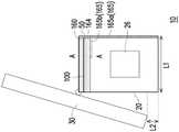
图2是图1的电子装置的主机体的剖面示意图。FIG. 2 is a schematic cross-sectional view of the main body of the electronic device of FIG. 1 .
图3是依照本发明的一实施例的一种天线模块的俯视示意图。FIG. 3 is a schematic top view of an antenna module according to an embodiment of the present invention.
图4是沿着图1的A-A线段的剖面示意图。FIG. 4 is a schematic cross-sectional view along line A-A of FIG. 1 .
图5是图3的天线模块的频率-VSWR的关系图。FIG. 5 is a frequency-VSWR relationship diagram of the antenna module of FIG. 3 .
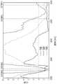
图6是图3的天线模块的频率-隔离度的关系图。FIG. 6 is a frequency-isolation relationship diagram of the antenna module of FIG. 3 .
图7是图3的天线模块的频率-天线效率的关系图。FIG. 7 is a frequency-antenna efficiency diagram of the antenna module of FIG. 3 .
图8是依照本发明的另一实施例的一种天线模块的俯视示意图。FIG. 8 is a schematic top view of an antenna module according to another embodiment of the present invention.
其中,附图标记说明如下:Among them, the reference numerals are described as follows:
θ1、θ2:夹角θ1, θ2: included angle
A1~A8、B1~B6、C1~C2:位置A1~A8, B1~B6, C1~C2: Position
D1、D2、D3:延伸方向D1, D2, D3: extension direction
L1、L7、L9、L12:厚度L1, L7, L9, L12: Thickness
L2、L5、L17:高度L2, L5, L17: Height
L3、L4、L13、L14:宽度L3, L4, L13, L14: Width
L6、L8、L11、L15、L16:距离L6, L8, L11, L15, L16: Distance
L10:长度L10: length
X、Y、Z:坐标X, Y, Z: Coordinates
10:电子装置10: Electronics
20:主机体20: main body
22:低频喇叭腔体22: Low frequency speaker cavity
24:高频喇叭腔体24: High frequency speaker cavity
26:低频喇叭26: Low frequency speakers
30:屏幕30: Screen
50:基板50: Substrate
60:屏蔽壳60: Shield shell
100、100a:天线模块100, 100a: Antenna module
110:第一天线110: first antenna
120:第二天线120: Second Antenna
122:主辐射体122: Main Radiator
124:副辐射体124: Secondary radiator
130:第一接地面130: First ground plane
132:第一沟槽132: First groove
140:第三天线140: Third Antenna
142:铜箔142: Copper foil
150:第二接地面150: Second ground plane
152:第二沟槽152: Second groove
160:第一挡墙160: First retaining wall
162:第二挡墙162: Second retaining wall
163、164:导通件163, 164: Conductor
165:金属件165: Metal Parts
165a:垂直板165a: Vertical Plate
165b:水平板165b: Horizontal Plate
170:第四天线170: Fourth Antenna
180:第三接地面180: Third ground plane
182:第三沟槽182: Third groove
具体实施方式Detailed ways
图1是依照本发明的一实施例的一种电子装置的示意图。图2是图1的电子装置的主机体的另一视角示意图。要说明的是,为了清楚表示天线模块相关结构,在图1与图2中,天线模块相关结构以实线表示。此外,图2仅绘示主机体而省略屏幕。FIG. 1 is a schematic diagram of an electronic device according to an embodiment of the present invention. FIG. 2 is a schematic diagram of another perspective view of the main body of the electronic device of FIG. 1 . It should be noted that, in order to clearly represent the related structure of the antenna module, in FIG. 1 and FIG. 2 , the related structure of the antenna module is represented by a solid line. In addition, FIG. 2 only shows the main body and omits the screen.
请参阅图1与图2,本实施例的电子装置10以智能音箱为例,但电子装置10的种类不以此为限制。电子装置10包括主机体20及屏幕30。屏幕30略高于主机体20的底部,距离主机体20的底部的高度L2(图1)大于等于15毫米,但不以此为限制。Please refer to FIG. 1 and FIG. 2 , the
如图2所示,主机体20包括位于中央的低频喇叭腔体22、位于两侧的低频喇叭26(宽度L4约为20毫米)及位于下侧的高频喇叭腔体24。As shown in FIG. 2 , the
在本实施例中,由于屏幕30为窄边框,没有多余空间供天线模块100(图3)配置,而使得天线模块100需要设置在主机体20内。主机体20的厚度L1(图1)约为47毫米,宽度L3约为240毫米,高度L5约为120毫米。在这样小尺寸的主机体20中,天线模块100具有特殊的设计而能够具有良好的隔离度及天线效率表现。下面将详细地说明天线模块100的结构。In this embodiment, since the
图3是依照本发明的一实施例的一种天线模块的俯视示意图。图4是沿着图1的A-A线段的剖面示意图。要说明的是,图4也为图3的侧视图。图3与图4的相对位置可参考坐标X-Y-Z。FIG. 3 is a schematic top view of an antenna module according to an embodiment of the present invention. FIG. 4 is a schematic cross-sectional view along line A-A of FIG. 1 . It should be noted that FIG. 4 is also a side view of FIG. 3 . The relative positions of FIG. 3 and FIG. 4 may refer to the coordinates X-Y-Z.
请参阅图3与图4,在本实施例中,天线模块100设置在基板50上,且包括一第一天线110、一第二天线120、一第一接地面130、一第三天线140及一第二接地面150。基板50例如是主机板(图3仅绘示出局部的基板),但不以此为限制。Please refer to FIG. 3 and FIG. 4 , in this embodiment, the
在本实施例中,第一天线110为蓝牙天线,馈入点在位置B1,由位置B1延伸至位置B2而构成PIFA天线架构,产生一单频(2.4GHz)的共振频率。第一天线110的尺寸大小为宽度4毫米,长度30毫米,但不以此为限制。In this embodiment, the
第二天线120为WIFI Main天线,馈入点在位置B3。第二天线120包括一主辐射体122(位置B3、B4)及一副辐射体124(位置C1、C2),主辐射体122与副辐射体124彼此分离且均连接至第一接地面130,副辐射体124靠近主辐射体122的馈入端,且主辐射体122与副辐射体124沿不同方向延伸。The
主辐射体122与副辐射体124共同构成开回路(open loop)天线架构。调整C1、C2路径长度可调整WiFi 2.4GHz的阻抗匹配频宽和共振频率点位置。位置C1、C2之间的长度L10为17毫米,但不以此为限制。WiFi Main天线的主辐射体122尺寸大小为宽20毫米,长35毫米,但不以此为限制。The
第三天线140为WiFi AUX天线,馈入点B5,通过位置B5至位置B6的路径构成PIFA天线架构,产生双频天线特性。调整B5、B6路径长度可调整WiFi 2.4GHz的共振频率点位置。第三天线140的宽度L13为7毫米至8毫米,长25毫米,但不以此为限制。The
在本实施例中,第二天线120位于第一天线110及第三天线140之间,第一天线110的延伸方向D1不平行于第二天线120的延伸方向D2,第二天线120的延伸方向D2不平行于第三天线140的延伸方向D1。In this embodiment, the
具体地说,第一天线110的延伸方向D1与第二天线120的主辐射体122延伸方向D2之间的夹角θ1介于45至75度,但不以此为限制。第二天线120的主辐射体122的延伸方向D2与第三天线140的延伸方向D1之间的夹角θ1介于45至75度,但不以此为限制。此外,第一天线110的延伸方向也可不平行于第三天线140的延伸方向,不以图式为限制。Specifically, the included angle θ1 between the extending direction D1 of the
由上述配置,即便第一天线110与第二天线120之间的距离(介于80毫米至100毫米之间)及第二天线120与第三天线140之间的距离(介于15毫米至20毫米之间)很小,第一天线110、第二天线120与第三天线140相互之间仍可具有较佳的隔离度。With the above configuration, even if the distance between the
此外,由图3可见,第一接地面130位于第一天线110及第二天线120之间且连接于第一天线110及第二天线120。第一接地面130的长度约为100毫米至110毫米之间,宽度L14约为40毫米,但不以此为限制。In addition, as can be seen from FIG. 3 , the
第一接地面130具有靠近第一天线110的一第一沟槽132,第一沟槽132被位置A1、A2、A3、A4围绕。在本实施例中,第一沟槽132的长度介于12毫米至15毫米,例如14.6毫米或是12.8毫米,但不以此为限制。第一沟槽132的宽度介于4毫米至6毫米,例如4.9毫米,但不以此为限制。The
在本实施例中,第二天线120分离于第三天线140,第二天线120与第三天线140之间的距离L11为17.5毫米,但不以此为限制。第二接地面150位于第二天线120及第三天线140之间且连接于第三天线140。第三天线140与第二接地面150之间通过铜箔142连接,铜箔142的厚度L12为0.5毫米,铜箔142的高度L17(图4)为6毫米,但不以此为限制。In this embodiment, the
第二接地面150与第二天线120与第一接地面130分离。第二接地面150与第一接地面130之间的距离L16(图4)为5毫米。第二接地面150例如是铜箔。第二接地面150具有一第二沟槽152,第一沟槽132的延伸方向D1平行于第二沟槽152的延伸方向D1。The
第二沟槽152被位置A5、A6、A7、A8围绕。在本实施例中,第二沟槽152的长度介于22毫米至26毫米,例如24毫米。第二沟槽152的宽度介于0.5毫米至1.5毫米,例如1毫米,但不以此为限制。调整第二沟槽152的尺寸可调整第二天线120与第三天线140之间的隔离度。The
在本实施例的天线模块100中,位于第一天线110及第二天线120之间的第一接地面130具有第一沟槽132,且位于第二天线120及第三天线140之间的第二接地面150具有第二沟槽152。经实验,上述配置进一步增加第一天线110、第二天线120及第三天线140相互之间的隔离度。In the
另外,天线模块100还包括一第一挡墙160及一第二挡墙162。在本实施例中,第一挡墙160及第二挡墙162为导电泡棉,但第一挡墙160及第二挡墙162的种类不以此为限制。In addition, the
第一挡墙160垂直配置于第一接地面130靠近第一沟槽132处,且导通于第一接地面130。第一天线110与第一挡墙160之间的距离L6为9毫米,第一挡墙160的厚度L7为2毫米至3毫米,但不以此为限制。在本实施例中,第一挡墙160位于第一天线110与第一沟槽132之间,例如是位置A1、A2处。在其他实施例中,第一沟槽132也可位于第一天线110与第一挡墙160之间,例如是位置A3、A4处。The
第二挡墙162垂直配置于第一接地面130靠近第二天线120处,且导通于第一接地面130。第二挡墙162的厚度L9为2毫米至3毫米,但不以此为限制。The
第一天线110及第二天线120位于第一挡墙160与第二挡墙162的两侧。第一挡墙160及第二挡墙162可用来使辐射能量集中,降低天线之间的彼此干扰,也可阻隔基板50(主机板)上的杂讯源(未绘示)对无线传输的影响。在本实施例中,第一挡墙160与第二挡墙162之间的距离L8为90毫米至92毫米,但不以此为限制。The
再者,在本实施例中,天线模块100还包括一金属件165,配置于第一接地面130的一侧且分离于第一接地面130。在本实施例中,金属件165是电子装置10的散热片,其可作为系统接地面。由图1可见,金属件165包括垂直板165a与水平板165b,但金属件165的形状不以此为限制。Furthermore, in this embodiment, the
如图4所示,金属件165的水平板165b与第一接地面130之间设有屏蔽壳60。屏蔽壳60约为2毫米至3毫米厚,但不以此为限制。设有第一接地面130的基板50位在屏蔽壳60上,屏蔽壳60位在金属件165上。屏蔽壳60有开孔供第一接地面130通过导通件163、164连接至金属件165。基板50可通过螺丝(未绘示)或是内部导通孔来通过导通件163、164搭接至金属件165,而可提升系统接地效果。As shown in FIG. 4 , a shielding
此外,第二接地面150延伸至金属件165,第三天线140与金属件165之间的距离L15为16毫米,但不以此为限制。第三天线140通过第二接地面150搭接至金属件165。In addition, the
图5是图3的天线模块的频率-VSWR的关系图。请参阅图5,在本实施例中,第一天线110、第二天线120与第三天线140在2400MHz至2500MHz及5150MHz至5875MHz之间的频段的VSWR值小于3,而具有良好的表现。FIG. 5 is a frequency-VSWR relationship diagram of the antenna module of FIG. 3 . Referring to FIG. 5 , in the present embodiment, the VSWR values of the
图6是图3的天线模块的频率-隔离度的关系图。请参阅图6,在本实施例中,第二天线120与第三天线140之间的隔离度为-15dB,第一天线110与第二天线120之间的隔离度以及第一天线110与第三天线140之间的隔离度更是低于-25dB。相较于现有的将第一天线110与第二天线120平行地配置且无第一沟槽132的设计第一天线110与第二天线120之间的隔离度仅在-10dB,本实施例的天线模块100的隔离度有相当良好的表现。FIG. 6 is a frequency-isolation relationship diagram of the antenna module of FIG. 3 . Referring to FIG. 6 , in this embodiment, the isolation between the
图7是图3的天线模块的频率-天线效率的关系图。请参阅图7,在本实施例中,第一天线110的低频的天线效率为-1.9dBi至-2.6dBi,而高频的天线效率为-2.4dBi至-3.4dBi。第二天线120的低频效率为-2.0dBi至-2.2dBi,而高频天线效率为-1.4dBi至-2.1dBi。第三天线140的低频效率为-1.6dBi至-1.7dBi,而高频天线效率为-0.9dBi至-2.0dBi。也就是说,无论在2.4GHz或5GHz频带内的天线效率都可大于-3.5dBi,而具有良好的表现。此外,在本实施例中,任两天线的封包相关系数ECC(Envelope Correlation Coefficient)可在0.1以内,而具有良好的表现。FIG. 7 is a frequency-antenna efficiency diagram of the antenna module of FIG. 3 . Referring to FIG. 7 , in this embodiment, the antenna efficiency of the
另外,现有5G技术的Sub 6G天线有支援4x4 MIMO多天线配置时,这些天线可以图8的方式来排列。图8是依照本发明的另一实施例的一种天线模块的俯视示意图。请参阅图8,天线模块100a还包括一第四天线170及一第三接地面180。第一天线110位于第四天线170与第二天线120之间,第四天线170的延伸方向D3不平行于第一天线110的延伸方向D1。第四天线170的延伸方向D3与第一天线110的延伸方向D1之间的夹角θ2例如介于30度至75度之间。In addition, when the existing 5G technology Sub 6G antenna supports 4x4 MIMO multi-antenna configuration, these antennas can be arranged as shown in Figure 8. FIG. 8 is a schematic top view of an antenna module according to another embodiment of the present invention. Please refer to FIG. 8 , the antenna module 100 a further includes a
第三接地面180位于第四天线170与第一天线110之间,第三接地面180例如是铜箔。第四天线170通过第三接地面180延伸至金属件162,以连接至系统接地面。第三接地面180具有一第三沟槽182。The
在本实施例中,第一天线110与第二天线120可以印刷在基板50(图3)上,通过第一接地面130来搭接到金属件165上。第三天线140与第四天线170可以通过第二接地面150与第三接地面180(独立的小块电路板或是铜箔)及传输线来搭接到金属件165上。上述配置可使得第一天线110与第四天线170具有良好的隔离度与天线效率。In this embodiment, the
综上所述,本发明的天线模块的第一天线的延伸方向不平行于第二天线的延伸方向,第二天线的延伸方向不平行于第三天线的延伸方向。此外,位于第一天线及第二天线之间的第一接地面具有第一沟槽,且位于第二天线及第三天线之间的第二接地面具有第二沟槽。上述配置可有效增加第一天线、第二天线及第三天线之间的隔离度,且使第一天线、第二天线及第三天线具有良好的天线效率。To sum up, the extension direction of the first antenna of the antenna module of the present invention is not parallel to the extension direction of the second antenna, and the extension direction of the second antenna is not parallel to the extension direction of the third antenna. In addition, the first ground plane located between the first antenna and the second antenna has a first trench, and the second ground plane located between the second antenna and the third antenna has a second trench. The above configuration can effectively increase the isolation between the first antenna, the second antenna and the third antenna, and make the first antenna, the second antenna and the third antenna have good antenna efficiency.
Claims (10)
Applications Claiming Priority (2)
| Application Number | Priority Date | Filing Date | Title |
|---|---|---|---|
| TW109136489 | 2020-10-21 | ||
| TW109136489ATWI746221B (en) | 2020-10-21 | 2020-10-21 | Antenna module |
Publications (2)
| Publication Number | Publication Date |
|---|---|
| CN114389035Atrue CN114389035A (en) | 2022-04-22 |
| CN114389035B CN114389035B (en) | 2025-08-26 |
Family
ID=79907490
Family Applications (1)
| Application Number | Title | Priority Date | Filing Date |
|---|---|---|---|
| CN202111226624.1AActiveCN114389035B (en) | 2020-10-21 | 2021-10-21 | antenna module |
Country Status (3)
| Country | Link |
|---|---|
| US (1) | US11688936B2 (en) |
| CN (1) | CN114389035B (en) |
| TW (1) | TWI746221B (en) |
Families Citing this family (1)
| Publication number | Priority date | Publication date | Assignee | Title |
|---|---|---|---|---|
| WO2023022017A1 (en)* | 2021-08-18 | 2023-02-23 | 株式会社村田製作所 | Antenna device |
Citations (14)
| Publication number | Priority date | Publication date | Assignee | Title |
|---|---|---|---|---|
| CN104103888A (en)* | 2014-08-06 | 2014-10-15 | 广东欧珀移动通信有限公司 | Mobile phone and antenna thereof |
| US20140368405A1 (en)* | 2013-06-18 | 2014-12-18 | Telefonaktiebolaget L M Ericsson (Publ) | Inverted F-Antennas at a Wireless Communication Node |
| KR20160061770A (en)* | 2014-11-24 | 2016-06-01 | 엘에스엠트론 주식회사 | Internal antenna module for vehicle |
| CN106549218A (en)* | 2015-09-22 | 2017-03-29 | 和硕联合科技股份有限公司 | Antenna module |
| TW201728007A (en)* | 2016-01-29 | 2017-08-01 | 環旭電子股份有限公司 | Antenna for wireless module application |
| CN107257023A (en)* | 2017-05-31 | 2017-10-17 | 维沃移动通信有限公司 | A kind of terminal multi-antenna structure and mobile terminal |
| CN108448250A (en)* | 2015-07-23 | 2018-08-24 | 广东欧珀移动通信有限公司 | Antenna system and communication terminal using the antenna system |
| CN110311229A (en)* | 2019-07-04 | 2019-10-08 | 京信通信技术(广州)有限公司 | Antenna and its reflector |
| US20200058992A1 (en)* | 2016-11-17 | 2020-02-20 | Huawei Technologies Co., Ltd. | Communications Terminal |
| CN110994196A (en)* | 2018-10-02 | 2020-04-10 | 纬创资通股份有限公司 | Antenna system |
| US20200235495A1 (en)* | 2019-01-21 | 2020-07-23 | Pegatron Corporation | Electronic device and antenna structure thereof |
| WO2020159155A1 (en)* | 2019-01-28 | 2020-08-06 | Samsung Electronics Co., Ltd. | Gps antenna structure for electronic terminal and electronic terminal |
| US20210367326A1 (en)* | 2020-05-21 | 2021-11-25 | Wistron Neweb Corporation | Mobile device and antenna module thereof |
| US20250007163A1 (en)* | 2023-06-30 | 2025-01-02 | Pegatron Corporation | Electronic device |
Family Cites Families (9)
| Publication number | Priority date | Publication date | Assignee | Title |
|---|---|---|---|---|
| WO2006097496A1 (en)* | 2005-03-15 | 2006-09-21 | Fractus, S.A. | Slotted ground-plane used as a slot antenna or used for a pifa antenna |
| TW201222975A (en)* | 2010-11-30 | 2012-06-01 | Tecom Co Ltd | Wide band antenna |
| TWM435740U (en)* | 2012-03-22 | 2012-08-11 | Wistron Neweb Corp | For a wireless communication device antenna combination wireless communication device, |
| TWI533506B (en)* | 2014-04-25 | 2016-05-11 | 國立中山大學 | Communication device and wideband decoupled dual-antenna element therein |
| US10347977B1 (en)* | 2017-05-24 | 2019-07-09 | Amazon Technologies, Inc. | Multi-polarization antenna system on a single circuit board |
| TWI678841B (en) | 2018-03-23 | 2019-12-01 | 和碩聯合科技股份有限公司 | Electronic device and antenna assembly thereof |
| CN209088056U (en) | 2018-11-12 | 2019-07-09 | 深圳绿米联创科技有限公司 | Integrated circuit board and gateway |
| TWI713254B (en)* | 2019-11-25 | 2020-12-11 | 和碩聯合科技股份有限公司 | Antenna module |
| TWI713259B (en)* | 2019-12-05 | 2020-12-11 | 和碩聯合科技股份有限公司 | Antenna structure |
- 2020
- 2020-10-21TWTW109136489Apatent/TWI746221B/enactive
- 2021
- 2021-09-08USUS17/469,787patent/US11688936B2/enactiveActive
- 2021-10-21CNCN202111226624.1Apatent/CN114389035B/enactiveActive
Patent Citations (14)
| Publication number | Priority date | Publication date | Assignee | Title |
|---|---|---|---|---|
| US20140368405A1 (en)* | 2013-06-18 | 2014-12-18 | Telefonaktiebolaget L M Ericsson (Publ) | Inverted F-Antennas at a Wireless Communication Node |
| CN104103888A (en)* | 2014-08-06 | 2014-10-15 | 广东欧珀移动通信有限公司 | Mobile phone and antenna thereof |
| KR20160061770A (en)* | 2014-11-24 | 2016-06-01 | 엘에스엠트론 주식회사 | Internal antenna module for vehicle |
| CN108448250A (en)* | 2015-07-23 | 2018-08-24 | 广东欧珀移动通信有限公司 | Antenna system and communication terminal using the antenna system |
| CN106549218A (en)* | 2015-09-22 | 2017-03-29 | 和硕联合科技股份有限公司 | Antenna module |
| TW201728007A (en)* | 2016-01-29 | 2017-08-01 | 環旭電子股份有限公司 | Antenna for wireless module application |
| US20200058992A1 (en)* | 2016-11-17 | 2020-02-20 | Huawei Technologies Co., Ltd. | Communications Terminal |
| CN107257023A (en)* | 2017-05-31 | 2017-10-17 | 维沃移动通信有限公司 | A kind of terminal multi-antenna structure and mobile terminal |
| CN110994196A (en)* | 2018-10-02 | 2020-04-10 | 纬创资通股份有限公司 | Antenna system |
| US20200235495A1 (en)* | 2019-01-21 | 2020-07-23 | Pegatron Corporation | Electronic device and antenna structure thereof |
| WO2020159155A1 (en)* | 2019-01-28 | 2020-08-06 | Samsung Electronics Co., Ltd. | Gps antenna structure for electronic terminal and electronic terminal |
| CN110311229A (en)* | 2019-07-04 | 2019-10-08 | 京信通信技术(广州)有限公司 | Antenna and its reflector |
| US20210367326A1 (en)* | 2020-05-21 | 2021-11-25 | Wistron Neweb Corporation | Mobile device and antenna module thereof |
| US20250007163A1 (en)* | 2023-06-30 | 2025-01-02 | Pegatron Corporation | Electronic device |
Also Published As
| Publication number | Publication date |
|---|---|
| TW202218244A (en) | 2022-05-01 |
| US11688936B2 (en) | 2023-06-27 |
| TWI746221B (en) | 2021-11-11 |
| CN114389035B (en) | 2025-08-26 |
| US20220123461A1 (en) | 2022-04-21 |
Similar Documents
| Publication | Publication Date | Title |
|---|---|---|
| CN111052508B (en) | Vertical end-fire antenna | |
| TWI724635B (en) | Antenna structure and electronic device | |
| CN112397898B (en) | Antenna array components and electronic equipment | |
| US11862866B2 (en) | Antenna module and electronic device | |
| WO2023040561A1 (en) | Antenna module and communication device | |
| WO2018018474A1 (en) | Wireless receiving/transmitting device and base station | |
| WO2022017220A1 (en) | Electronic device | |
| CN114665260B (en) | An antenna and communication device | |
| WO2024120287A1 (en) | Antenna structure and electronic device | |
| US7167132B2 (en) | Small antenna and a multiband antenna | |
| CN114447605A (en) | Multi-band fusion antenna assembly | |
| US12095146B2 (en) | Electronic device | |
| CN116137387A (en) | antenna module | |
| CN114389035A (en) | Antenna module | |
| US12327907B2 (en) | Electronic device | |
| CN115241646A (en) | Antenna and communication equipment | |
| US12142843B2 (en) | Electronic device | |
| US10700409B2 (en) | Back cover for electronic device and electronic device | |
| CN102157794A (en) | Three-frequency-band antenna generated by resonance | |
| CN103296423A (en) | Antenna device and array antenna | |
| CN115149250A (en) | Antenna and communication equipment | |
| WO2024179404A1 (en) | Antenna structure and electronic device | |
| WO2025201318A1 (en) | Electronic device | |
| WO2025180320A1 (en) | Electronic device | |
| CN116365222A (en) | Plane double circular polarized antenna based on orthogonal magnetic dipoles |
Legal Events
| Date | Code | Title | Description |
|---|---|---|---|
| PB01 | Publication | ||
| PB01 | Publication | ||
| SE01 | Entry into force of request for substantive examination | ||
| SE01 | Entry into force of request for substantive examination | ||
| GR01 | Patent grant | ||
| GR01 | Patent grant |