CN114383006A - An underwater multifunctional flexible support device - Google Patents
An underwater multifunctional flexible support deviceDownload PDFInfo
- Publication number
- CN114383006A CN114383006ACN202210072020.4ACN202210072020ACN114383006ACN 114383006 ACN114383006 ACN 114383006ACN 202210072020 ACN202210072020 ACN 202210072020ACN 114383006 ACN114383006 ACN 114383006A
- Authority
- CN
- China
- Prior art keywords
- fixing plate
- support device
- sensor
- type
- plate
- Prior art date
- Legal status (The legal status is an assumption and is not a legal conclusion. Google has not performed a legal analysis and makes no representation as to the accuracy of the status listed.)
- Pending
Links
- 230000005484gravityEffects0.000claimsabstractdescription17
- 239000011810insulating materialSubstances0.000claimsabstractdescription10
- 239000004677NylonSubstances0.000claimsdescription7
- 230000003139buffering effectEffects0.000claimsdescription7
- 229920001778nylonPolymers0.000claimsdescription7
- 239000004697PolyetherimideSubstances0.000claimsdescription6
- 229920001601polyetherimidePolymers0.000claimsdescription6
- 229920006324polyoxymethylenePolymers0.000claimsdescription6
- 239000013585weight reducing agentSubstances0.000claimsdescription6
- 238000009434installationMethods0.000claimsdescription4
- 230000002093peripheral effectEffects0.000claimsdescription4
- 229930040373ParaformaldehydeNatural products0.000claimsdescription3
- -1polyoxymethylenePolymers0.000claimsdescription3
- 230000008719thickeningEffects0.000claimsdescription3
- 239000007769metal materialSubstances0.000abstractdescription4
- 229910052755nonmetalInorganic materials0.000abstractdescription4
- 239000000463materialSubstances0.000description7
- 230000007613environmental effectEffects0.000description4
- 238000012360testing methodMethods0.000description4
- 241001474374BlenniusSpecies0.000description3
- 238000012544monitoring processMethods0.000description3
- 239000013535sea waterSubstances0.000description3
- XLYOFNOQVPJJNP-UHFFFAOYSA-NwaterSubstancesOXLYOFNOQVPJJNP-UHFFFAOYSA-N0.000description3
- 230000008859changeEffects0.000description2
- 230000007797corrosionEffects0.000description2
- 238000005260corrosionMethods0.000description2
- 238000013461designMethods0.000description2
- 238000000034methodMethods0.000description2
- 238000012986modificationMethods0.000description2
- 230000004048modificationEffects0.000description2
- 230000035945sensitivityEffects0.000description2
- 241000195493CryptophytaSpecies0.000description1
- 238000010521absorption reactionMethods0.000description1
- 238000013480data collectionMethods0.000description1
- 230000000694effectsEffects0.000description1
- 238000011156evaluationMethods0.000description1
- 238000012423maintenanceMethods0.000description1
- 239000002184metalSubstances0.000description1
- 238000011160researchMethods0.000description1
- 230000000630rising effectEffects0.000description1
- 239000013049sedimentSubstances0.000description1
Images


Classifications
- F—MECHANICAL ENGINEERING; LIGHTING; HEATING; WEAPONS; BLASTING
- F16—ENGINEERING ELEMENTS AND UNITS; GENERAL MEASURES FOR PRODUCING AND MAINTAINING EFFECTIVE FUNCTIONING OF MACHINES OR INSTALLATIONS; THERMAL INSULATION IN GENERAL
- F16M—FRAMES, CASINGS OR BEDS OF ENGINES, MACHINES OR APPARATUS, NOT SPECIFIC TO ENGINES, MACHINES OR APPARATUS PROVIDED FOR ELSEWHERE; STANDS; SUPPORTS
- F16M11/00—Stands or trestles as supports for apparatus or articles placed thereon ; Stands for scientific apparatus such as gravitational force meters
- F16M11/02—Heads
- F16M11/04—Means for attachment of apparatus; Means allowing adjustment of the apparatus relatively to the stand
- F—MECHANICAL ENGINEERING; LIGHTING; HEATING; WEAPONS; BLASTING
- F16—ENGINEERING ELEMENTS AND UNITS; GENERAL MEASURES FOR PRODUCING AND MAINTAINING EFFECTIVE FUNCTIONING OF MACHINES OR INSTALLATIONS; THERMAL INSULATION IN GENERAL
- F16F—SPRINGS; SHOCK-ABSORBERS; MEANS FOR DAMPING VIBRATION
- F16F15/00—Suppression of vibrations in systems; Means or arrangements for avoiding or reducing out-of-balance forces, e.g. due to motion
- F16F15/02—Suppression of vibrations of non-rotating, e.g. reciprocating systems; Suppression of vibrations of rotating systems by use of members not moving with the rotating systems
- F16F15/04—Suppression of vibrations of non-rotating, e.g. reciprocating systems; Suppression of vibrations of rotating systems by use of members not moving with the rotating systems using elastic means
- F16F15/08—Suppression of vibrations of non-rotating, e.g. reciprocating systems; Suppression of vibrations of rotating systems by use of members not moving with the rotating systems using elastic means with rubber springs ; with springs made of rubber and metal
- F—MECHANICAL ENGINEERING; LIGHTING; HEATING; WEAPONS; BLASTING
- F16—ENGINEERING ELEMENTS AND UNITS; GENERAL MEASURES FOR PRODUCING AND MAINTAINING EFFECTIVE FUNCTIONING OF MACHINES OR INSTALLATIONS; THERMAL INSULATION IN GENERAL
- F16M—FRAMES, CASINGS OR BEDS OF ENGINES, MACHINES OR APPARATUS, NOT SPECIFIC TO ENGINES, MACHINES OR APPARATUS PROVIDED FOR ELSEWHERE; STANDS; SUPPORTS
- F16M11/00—Stands or trestles as supports for apparatus or articles placed thereon ; Stands for scientific apparatus such as gravitational force meters
- F16M11/20—Undercarriages with or without wheels
- F16M11/22—Undercarriages with or without wheels with approximately constant height, e.g. with constant length of column or of legs
- H—ELECTRICITY
- H02—GENERATION; CONVERSION OR DISTRIBUTION OF ELECTRIC POWER
- H02G—INSTALLATION OF ELECTRIC CABLES OR LINES, OR OF COMBINED OPTICAL AND ELECTRIC CABLES OR LINES
- H02G9/00—Installations of electric cables or lines in or on the ground or water
Landscapes
- Engineering & Computer Science (AREA)
- General Engineering & Computer Science (AREA)
- Mechanical Engineering (AREA)
- Chemical & Material Sciences (AREA)
- Combustion & Propulsion (AREA)
- Physics & Mathematics (AREA)
- Acoustics & Sound (AREA)
- Aviation & Aerospace Engineering (AREA)
- Testing Or Calibration Of Command Recording Devices (AREA)
Abstract
Translated fromChinese
Description
Translated fromChinese技术领域technical field
本发明涉及海上设备技术领域,尤其涉及一种水下多功能柔性支撑装置。The invention relates to the technical field of marine equipment, in particular to an underwater multifunctional flexible support device.
背景技术Background technique
目前的水下支撑装置大多为精细化结构设计,针对特定的磁传感器进行总体方案设计,一旦磁传感器进行细微的调整,尤其是同类型不同重量的磁传感器,对于水下支撑装置的整体重心存在较大影响,故其通用性较差,无法适应临时磁传感器的重量变化;而且,现有水下支撑装置对水下地貌结构(如水下坡度、水底平整度、泥沙等)适用性较差,因考虑其金属材质结构和重量综合权衡评估,一般很难做得方正稳妥,且往往重心偏高,因此对水下装置的布置技能和水下地貌的平整度都更苛刻,试验数据采集可靠性也相对更低;同时金属材质的框架存在干扰同步工作的磁传感器信息采集与监测灵敏度,甚至产生误判直接影响各磁传感器的功能可靠性,现有的水下支撑装置也缺乏对磁传感器的电缆线束绑扎和固定,不能有效防止水下生物、海藻等不确定环境因素对电缆线束的干扰损坏,进而影响整体装置系统的正常工作。Most of the current underwater support devices are of refined structure design, and the overall scheme design is carried out for a specific magnetic sensor. Once the magnetic sensor is finely adjusted, especially the magnetic sensors of the same type and different weights, the overall center of gravity of the underwater support device exists. Therefore, its versatility is poor, and it cannot adapt to the weight change of the temporary magnetic sensor; moreover, the existing underwater support device has poor applicability to underwater geomorphological structures (such as underwater slope, bottom flatness, sediment, etc.). , due to the comprehensive trade-off evaluation of its metal material structure and weight, it is generally difficult to be square and stable, and the center of gravity is often high, so the layout skills of underwater devices and the flatness of underwater landforms are more demanding, and test data collection is reliable. At the same time, the metal frame has interference with the information collection and monitoring sensitivity of magnetic sensors that work synchronously, and even misjudgment directly affects the functional reliability of each magnetic sensor. The binding and fixing of the cable harness cannot effectively prevent the interference and damage of the cable harness due to uncertain environmental factors such as underwater organisms and seaweed, which in turn affects the normal operation of the overall device system.
鉴于此,研究一种通用性好、重心可调且采集数据可靠性高的水下多功能柔性支撑装置是本技术领域人员急需解决的技术问题。In view of this, it is an urgent technical problem for those skilled in the art to research an underwater multi-functional flexible support device with good versatility, adjustable center of gravity and high reliability of collected data.
发明内容SUMMARY OF THE INVENTION
为解决上述技术问题,本发明提供的一种水下多功能柔性支撑装置,包括非金属绝缘材质制作而成并用于安装若干个不同类别传感器的框架,所述框架包括上固定板、下固定板和若干个支撑立柱,上固定板和下固定板的尺寸相同且横向平行设置,若干个支撑立柱均匀布设于上固定板上用于安装位于上固定板和下固定板之间的第一类传感器,每一个支撑立柱的上端端部均穿过上固定板并置于上固定板的上侧,每一个支撑立柱的下端端部均穿过下固定板并置于下固定板的下侧,上固定板和下固定板上均设有若干个排水减重孔和若干个第一通孔,第一通孔可用于安装位于上固定板和下固定板之间的第二类传感器,排水减重孔用于加装重物以调节支撑装置的整体重心,且上固定板上还设有用于安装第三类传感器的第二通孔。In order to solve the above technical problems, an underwater multifunctional flexible support device provided by the present invention includes a frame made of non-metal insulating material and used to install several different types of sensors, the frame includes an upper fixing plate and a lower fixing plate. and several supporting columns, the upper and lower fixing plates have the same size and are arranged in parallel horizontally, and several supporting columns are evenly arranged on the upper fixing plate for installing the first type of sensors located between the upper and lower fixing plates , the upper end of each supporting column passes through the upper fixing plate and is placed on the upper side of the upper fixing plate, and the lower end of each supporting column passes through the lower fixing plate and is placed on the lower side of the lower fixing plate. The fixing plate and the lower fixing plate are provided with several drainage and weight-reducing holes and several first through holes. The first through-holes can be used to install the second type sensor located between the upper fixing plate and the lower fixing plate. Drainage and weight reduction The hole is used for adding heavy objects to adjust the overall center of gravity of the support device, and the upper fixing plate is also provided with a second through hole for installing the third type of sensor.
优选地,每一个所述支撑立柱上均平行固定套设有上垫板和下垫板,所述上垫板与上固定板的上侧面固定连接,下垫板与下固定板的下侧面固定连接,上固定板的下侧面设有与上垫板相匹配的上法兰,下固定板的上侧面设有与下垫板相匹配的下法兰,支撑立柱通过上垫板、下垫板、上法兰和下法兰分别与上固定板和下固定板可拆卸固定连接。Preferably, an upper backing plate and a lower backing plate are fixedly sleeved on each of the supporting columns in parallel, the upper backing plate is fixedly connected to the upper side of the upper fixing plate, and the lower backing plate is fixed to the lower side of the lower fixing plate Connection, the lower side of the upper fixing plate is provided with an upper flange that matches the upper backing plate, the upper side of the lower fixing plate is provided with a lower flange that matches the lower backing plate, and the supporting column passes through the upper backing plate and the lower backing plate. , The upper flange and the lower flange are respectively detachably and fixedly connected with the upper fixing plate and the lower fixing plate.
优选地,每一个所述支撑立柱上均设有与第一类传感器下端端部相匹配的台阶以及若干个用于对第一类传感器进行限位并位于第一类传感器下端的螺孔,若干个螺孔均匀分布于支撑立柱的外周侧壁上,第一类传感器上端端部设有用于调节松紧程度并具有缓冲作用的第一橡胶垫和第一限位环。Preferably, each of the supporting columns is provided with a step matching the lower end of the first-type sensor and a plurality of screw holes for limiting the first-type sensor and located at the lower end of the first-type sensor. The screw holes are evenly distributed on the outer peripheral side wall of the support column, and the upper end of the first type sensor is provided with a first rubber pad and a first limit ring for adjusting the tightness and buffering.
优选地,每一个所述支撑立柱上端均设有若干个用于限位和防松脱的螺纹限位孔,若干个所述螺纹限位孔均匀布设于上垫板的上侧。Preferably, the upper end of each of the supporting columns is provided with a plurality of threaded limit holes for positioning and anti-loosening, and the plurality of the threaded limit holes are evenly arranged on the upper side of the upper backing plate.
优选地,还包括与第二类传感器两端端部相匹配的法兰盘,第二类传感器通过法兰盘分别嵌套设于上固定板的第一通孔和下固定板的第一通孔内。Preferably, it also includes flanges matching the two ends of the second type of sensor, and the second type of sensor is respectively nested in the first through hole of the upper fixing plate and the first through hole of the lower fixing plate through the flange. inside the hole.
优选地,所述上垫板和上法兰均通过螺栓分别与上固定板可拆卸固定连接,下垫板和下法兰均通过螺栓分别与下固定板可拆卸固定连接。Preferably, the upper backing plate and the upper flange are respectively detachably and fixedly connected to the upper fixing plate by bolts, and the lower backing plate and the lower flange are respectively detachably and fixedly connected to the lower fixing plate by bolts.
优选地,所述第二类传感器的端部设有用于调节松紧程度且具有缓冲作用的第二橡胶垫和第二限位环。Preferably, the end of the second type of sensor is provided with a second rubber pad and a second limit ring for adjusting the tightness and having a buffering effect.
优选地,每一个所述支撑立柱的下端端部与下垫板之间的间距为180-200mm,且支撑立柱的下端端部与下垫板之间的部分通过加厚方式进行加强处理以保证框架平稳运行。Preferably, the distance between the lower end of each supporting column and the lower backing plate is 180-200 mm, and the part between the lower end of the supporting column and the lower backing plate is reinforced by thickening to ensure that The frame runs smoothly.
优选地,所述上固定板和下固定板上还设有若干个用于对电缆线束进行绑扎固定的线束孔。Preferably, the upper fixing plate and the lower fixing plate are further provided with a plurality of wire harness holes for tying and fixing the cable harness.
优选地,所述框架采用MC尼龙、聚甲醛POM或聚醚酰亚胺PEI加工制作而成。Preferably, the frame is made of MC nylon, polyoxymethylene POM or polyetherimide PEI.
与现有技术相比,本发明所具有的优点主要体现在以下几个方面:Compared with the prior art, the advantages that the present invention has are mainly reflected in the following aspects:
1)本发明中采用非金属绝缘材质制作安装各类传感器的框架,进而可制作较大尺寸的框架结构,使得支撑装置的整体结构重心更低更稳,对水下支撑装置的布置技能和水下地貌平整度要求都更低,从而传感器采集的试验数据可靠性更高;同时非金属绝缘材质也从根本上消除了对不同磁传感器的干扰和影响,最大限度提升磁传感器的信息采集与监测灵敏度;而且,通过在上固定板和下固定板上设置排水减重孔用于加装重物可实现支撑装置整体结构的重心调节。1) In the present invention, non-metallic insulating material is used to make the frame for installing various sensors, and then a larger-sized frame structure can be made, so that the overall structure of the support device has a lower and more stable center of gravity, and the layout skills of the underwater support device and water. The requirements for the flatness of the lower landform are lower, so the test data collected by the sensor is more reliable; at the same time, the non-metallic insulating material also fundamentally eliminates the interference and influence on different magnetic sensors, and maximizes the information collection and monitoring of the magnetic sensors. Moreover, by arranging drainage and weight-reducing holes on the upper fixing plate and the lower fixing plate for adding heavy objects, the center of gravity of the overall structure of the support device can be adjusted.
2)本发明通过在上固定板和下固定板上设置若干个预留的第一通孔位置,既能够实现磁传感器的位置调整以应对同类型不同重量的传感器变化,有效提升了该支撑装置的通用性,又能够用于加装重物进一步调节支撑装置整体结构的重心。2) In the present invention, by setting several reserved first through-hole positions on the upper fixing plate and the lower fixing plate, the position adjustment of the magnetic sensor can be realized to cope with the sensor changes of the same type and different weights, and the supporting device can be effectively improved. It is versatile, and can be used to install heavy objects to further adjust the center of gravity of the overall structure of the support device.
3)本发明通过在上固定板和下固定板上设置若干个线束孔,允许将多种不同类型磁传感器上的电缆线束有条不紊的捆扎固定在支撑装置的各个位置,尽可能的减少水下生物、海藻等不确定环境因素对电缆线束的干扰损坏,且其结构简单,使用寿命更长久,故其稳定可靠性强。3) The present invention allows the cable harnesses on a variety of different types of magnetic sensors to be bundled and fixed in various positions of the support device in an orderly manner by arranging several wire harness holes on the upper fixing plate and the lower fixing plate, so as to reduce underwater organisms as much as possible. , seaweed and other uncertain environmental factors interfere and damage the cable harness, and its simple structure and longer service life, so its stability and reliability are strong.
4)本发明通过在支撑立柱的上端设置螺纹限位孔进行限位和防松脱,有效保证了支撑装置的正常运行。4) The present invention effectively guarantees the normal operation of the support device by arranging threaded limit holes on the upper end of the support column to limit and prevent loosening.
5)本发明通过在第一类传感器端部和第二类传感器端部均设置橡胶垫和限位环,实现了各类传感器的松紧调节,同时也保证了各类传感器端部具有一定的缓冲作用。5) The present invention realizes the tightness adjustment of various sensors by setting rubber pads and limit rings at the end of the first type of sensor and the end of the second type of sensor, and also ensures that the end of each type of sensor has a certain buffer. effect.
附图说明Description of drawings
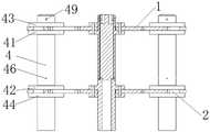
图1是本发明中一种水下多功能柔性支撑装置的结构示意图,Fig. 1 is the structural representation of a kind of underwater multifunctional flexible support device in the present invention,
图2是本发明中水下多功能柔性支撑装置的俯视图,Fig. 2 is the top view of the underwater multifunctional flexible support device in the present invention,
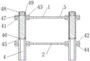
图3是图2的A-A剖视图,Fig. 3 is the A-A sectional view of Fig. 2,
图4是图2的B-B剖视图。FIG. 4 is a cross-sectional view taken along line B-B of FIG. 2 .
图中:1、上固定板,11、线束孔,2、下固定板,4、支撑立柱,41、上法兰,42、下法兰,43、上垫板,44、下垫板,45、台阶,46、螺孔,47、第一橡胶垫,48、第一限位环,49.螺纹限位孔,5、排水减重孔,6、第一通孔,7、第二通孔。In the figure: 1. Upper fixing plate, 11, Harness hole, 2. Lower fixing plate, 4. Supporting column, 41, Upper flange, 42, Lower flange, 43, Upper backing plate, 44, Lower backing plate, 45 , step, 46, screw hole, 47, first rubber pad, 48, first limit ring, 49. threaded limit hole, 5, drainage and weight reduction hole, 6, first through hole, 7, second through hole .
具体实施方式Detailed ways
为了使本技术领域的人员更好地理解本发明的技术方案,下面结合附图对本发明作进一步的详细说明。In order to make those skilled in the art better understand the technical solutions of the present invention, the present invention will be further described in detail below with reference to the accompanying drawings.
需要说明的是,以图1为例,垂直纸面向上为上,垂直纸面向下为下,上下方向为竖直方向,与竖直方向垂直的方向为水平方向。It should be noted that, taking FIG. 1 as an example, the vertical paper face up is upward, the vertical paper face downward is downward, the up-down direction is the vertical direction, and the direction perpendicular to the vertical direction is the horizontal direction.
如图1-图4所示,一种水下多功能柔性支撑装置,包括非金属绝缘材质制作而成并用于安装若干个不同类别传感器的框架,所述框架包括上固定板1、下固定板2和若干个支撑立柱4,上固定板1和下固定板2的尺寸相同且横向平行设置,若干个支撑立柱4均匀布设于上固定板1上用于安装位于上固定板1和下固定板2之间的第一类传感器,每一个支撑立柱4的上端端部均穿过上固定板1并置于上固定板1的上侧,每一个支撑立柱4的下端端部均穿过下固定板2并置于下固定板2的下侧,上固定板1和下固定板2上设有若干个排水减重孔5和若干个第一通孔6,第一通孔6可用于安装位于上固定板1和下固定板2之间的第二类传感器,排水减重孔5用于加装重物以调节支撑装置整体重心,且上固定板1上还设有用于安装第三类传感器的第二通孔7。As shown in Figures 1 to 4, an underwater multifunctional flexible support device includes a frame made of non-metallic insulating material and used to install several different types of sensors. The frame includes an
本实施例中,所述传感器包括第一类传感器、第二类传感器和第三类传感器三种类别,其中,第一类传感器设有四个,且该四个第一类传感器构成一个正方形,该四个第一类传感器分别竖直固定安装于上固定板1四个角的支撑立柱4上;第二类传感器设有一个,且该第二类传感器竖直安装于上固定板1和下固定板2之间;如图2所示,第三类传感器包括并列安装于上固定板1上侧面若干个第二通孔7内的电子仓传感器和罗经传感器。In this embodiment, the sensors include three types: the first type sensor, the second type sensor and the third type sensor, wherein, there are four first type sensors, and the four first type sensors form a square, The four sensors of the first type are respectively vertically and fixedly installed on the
本实施例中,通过采用非金属绝缘材质制作安装三类传感器的框架,进而能够制作较大尺寸的框架结构,使得支撑装置的整体结构重心更低更稳,而且,通过在上固定板1和下固定板2上设置排水减重孔5加装重物可实现支撑装置整体结构的重心调节,即通过螺栓连接物品所带来的自身重量来调节支撑装置的重心和平衡,因此,该支撑装置对水下布置技能和水下地貌平整度要求都更低,从而各类传感器采集的试验数据可靠性更高;同时非金属绝缘材质也从根本上消除了对各类传感器的干扰和影响,最大限度提升传感器的信息采集与监测灵敏度;若干个所述第一通孔6还可以对支撑立柱4的位置进行调整进而对各类传感器的位置进行微调,实现了对同类型不同重量传感器的变化,具有良好的通用性。In this embodiment, by using a non-metal insulating material to make a frame for installing the three types of sensors, a larger-sized frame structure can be made, so that the overall structure of the supporting device has a lower and more stable center of gravity. The
本实施例中,所述框架采用MC尼龙制作而成,在其他实施例中,也可以采用聚甲醛POM或聚醚酰亚胺PEI加工制作,还可以是尼龙PA系列和其他非金属材料,只要满足材料为非金属材质,材料的密度大于海水密度,材料抗拉强度大于等于75Mpa,材料吸水率小于等于1.4%,材料耐海水腐蚀性较强,材料环境温度在4-100℃之间即可。In this embodiment, the frame is made of MC nylon. In other embodiments, it can also be made of polyoxymethylene POM or polyetherimide PEI, and can also be nylon PA series and other non-metallic materials, as long as The material is non-metallic, the density of the material is greater than the density of sea water, the tensile strength of the material is greater than or equal to 75Mpa, the water absorption rate of the material is less than or equal to 1.4%, the material is highly resistant to seawater corrosion, and the ambient temperature of the material is between 4-100 ℃. .
需要说明的是,本实施例中,所述第一通孔6和第二通孔7还可以在未安装第二类传感器和第三类传感器之前进行大方量的通水,进而有效提高了支撑装置整体的下沉和/或上升效果。It should be noted that, in this embodiment, the first through
在其中一个实施例中,每一个所述支撑立柱4上均平行固定套设有上垫板43和下垫板44,所述上垫板43与上固定板1的上侧面固定连接,下垫板44与下固定板2的下侧面固定连接,上固定板1的下侧面设有与上垫板43相匹配的上法兰41,下固定板2的上侧面设有与下垫板44相匹配的下法兰42,支撑立柱4通过上垫板43、下垫板44、上法兰41和下法兰42分别与上固定板1和下固定板2可拆卸固定连接。In one of the embodiments, an
本实施例中,所述非金属绝缘材质为MC尼龙,考虑到MC尼龙做成分体式结构的可靠性不确定以及结构简化的安全性,所述支撑立柱4、上垫板43和下垫板44为一体成型,通过上法兰41与上垫板43匹配以及下法兰42与下垫板44匹配将支撑立柱4分别与上固定板1和下固定板2可拆卸固定连接,既保证了连接的稳定可靠性,同时又便于拆装维护。In this embodiment, the non-metallic insulating material is MC nylon. Considering the uncertainty of reliability of MC nylon as a split structure and the safety of simplified structure, the
在其中一个实施例中,每一个所述支撑立柱4上均设有与第一类传感器下端端部相匹配的台阶45以及若干个用于对第一类传感器进行限位并位于第一类传感器下端的螺孔46,若干个螺孔46均匀分布于支撑立柱4的外周侧壁上,第一类传感器上端端部设有用于调节松紧程度并具有缓冲作用的第一橡胶垫47和第一限位环48。In one of the embodiments, each of the
本实施例中,所述第一类传感器下端端部与台阶45匹配连接,在支撑立柱4的外周侧壁上均匀设置有四个螺孔46,相邻螺孔46之间的角度为90°,通过螺孔46与第一类传感器壁上对应孔匹配并通过螺栓可实现第一类传感器的精准限位,每个支撑立柱4上的螺孔46的位置应该保持方向一致以确保四个第一类传感器的对应螺孔46的指向一致。In this embodiment, the lower end of the first type sensor is matched and connected with the
在其中一个实施例中,每一个所述支撑立柱4上端均设有若干个用于限位和防松脱的螺纹限位孔49,若干个所述螺纹限位孔9均匀布设于上垫板43的上侧。本实施例中,通过螺栓与螺纹限位孔49匹配可对支撑立柱4进行限位,进而保证了支撑装置的正常运行,同时,所述螺纹限位孔49上的螺栓与第一橡胶垫47结合还可以对支撑立柱4内的第一类传感器进行卡位和施压。In one embodiment, the upper end of each of the
在其中一个实施例中,还包括与第二类传感器两端端部相匹配的法兰盘(图中未示出),第二类传感器通过法兰盘分别嵌套设于上固定板1的第一通孔6和下固定板2的第一通孔6内。本实施例中,所述法兰盘通过嵌套入第一通孔6固定在上固定板1和下固定板2内,第二类传感器的两端通过与法兰盘61匹配实现可拆卸固定。In one of the embodiments, it also includes flanges (not shown in the figure) matching the two ends of the second-type sensor, and the second-type sensors are respectively nested on the
在其中一个实施例中,所述上垫板43和上法兰41均通过螺栓分别与上固定板1可拆卸固定连接,下垫板42和下法兰42均通过螺栓分别与下固定板2可拆卸固定连接。本实施例中,所述上垫板43和上法兰41与上固定板1之间以及下垫板44和下法兰42与下固定板2之间均通过螺栓可拆卸固定连接,既能够有效保证保证支撑立柱4与上固定板1以及支撑立柱4与下固定板2之间的连接可靠性,同时便于部件的维护拆装。In one embodiment, the
在其中一个实施例中,所述第二类传感器的端部设有用于调节松紧程度且具有缓冲作用的第二橡胶垫(图中未示出)和第二限位环(图中未示出)。本实施例中,除了第一类传感器端部设置有用于调节松紧程度并具有缓冲作用的第一橡胶垫和第一限位环,所述第二类传感器端部同样设置有与第一橡胶垫和第一限位环材质、功能和安装位置均相同的第二橡胶垫和第二限位环。In one embodiment, the end of the second type of sensor is provided with a second rubber pad (not shown in the figure) and a second limiting ring (not shown in the figure) for adjusting the tightness and having a buffering effect ). In this embodiment, except that the end of the first type of sensor is provided with a first rubber pad and a first limit ring for adjusting the tightness and having a buffering effect, the end of the second type of sensor is also provided with a first rubber pad The second rubber pad and the second limit ring are the same in material, function and installation position as the first limit ring.
在其中一个实施例中,每一个所述支撑立柱4的下端端部与下垫板44之间的间距为180-220mm,且支撑立柱4的下端端部与下垫板44之间的部分通过加厚方式进行加强处理以保证框架平稳运行。为了确保支撑装置整体能够在海下平稳并保证各类传感器的正常运行,支撑立柱4下端长度约为200mm的部分进行加厚以加强支撑立柱3的承载能力。In one embodiment, the distance between the lower end of each of the supporting
在其中一个实施例中,所述上固定板1和下固定板2上还设有若干个用于对电缆线束进行绑扎固定的线束孔11。本实施例中,为了保证各种不同类型传感器的电缆线束有条不紊的捆扎固定在支撑装置的各个位置,尽可能的减少水下生物、海藻等不确定环境因素对电缆线束的干扰损坏,在上固定板1和下固定板2上设置若干个线束孔11对电缆线束进行绑扎固定,具有结构简单、使用寿命长久和稳定可靠的特点。一般而言,所述线束孔11的位置设于上固定板1和下固定板2上安装第一类传感器、第二类传感器和第三类传感器的周边。在其他实施例中,该线束孔11还可用于调节支撑装置整体的螺栓连接以及连接砝码块,同时也可以将电缆线束穿过排水减重孔5进行绑扎固定。In one embodiment, the
本发明所提供的水下多功能柔性支撑装置,所述框架采用耐海水腐蚀的高强度非金属材料MC尼龙制作而成,制作较大尺寸的框架结构,使得支撑装置的整体结构重心更低更稳,对水下支撑装置的布置技能和水下地貌平整度要求都更低,从而传感器采集的试验数据可靠性更高;同时非金属绝缘材质也从根本上消除了对不同磁传感器的干扰和影响,最大限度提升磁传感器的信息采集与监测灵敏度;而且,通过在上固定板和下固定板上设置排水减重孔用于加装重物可实现支撑装置整体结构的重心调节;同时,设置若干个预留的第一通孔,实现了磁传感器的位置调整以应对同类型不同重量的传感器变化,从而提升了该支撑装置的通用性;另外,上固定板1和下固定板2上的线束孔11还能对各类传感器的电缆线束进行绑扎固定,极大程度上能够减少水下生物、海藻等不确定环境因素对电缆线束的干扰损坏。In the underwater multi-functional flexible support device provided by the present invention, the frame is made of high-strength non-metallic material MC nylon that is resistant to seawater corrosion, and a frame structure of a larger size is made, so that the overall structure of the support device has a lower center of gravity and more It has lower requirements on the layout skills of the underwater support device and the flatness of the underwater landform, so the test data collected by the sensor is more reliable; at the same time, the non-metal insulating material also fundamentally eliminates the interference and interference to different magnetic sensors. In addition, the center of gravity of the overall structure of the support device can be adjusted by setting drainage and weight-reducing holes on the upper and lower fixing plates for installing heavy objects; at the same time, setting Several reserved first through holes realize the position adjustment of the magnetic sensor to cope with the sensor changes of the same type and different weights, thereby improving the versatility of the support device; The
以上对本发明所提供的一种水下多功能柔性支撑装置进行了详细介绍。本文中应用了具体个例对本发明的原理及实施方式进行了阐述,以上实施例的说明只是用于帮助理解本发明的核心思想。应当指出,对于本技术领域的普通技术人员来说,在不脱离本发明原理的前提下,还可以对本发明进行若干改进和修饰,这些改进和修饰也落入本发明权利要求的保护范围内。The underwater multifunctional flexible support device provided by the present invention has been described in detail above. The principles and implementations of the present invention are described herein by using specific examples, and the descriptions of the above embodiments are only used to help understand the core idea of the present invention. It should be pointed out that for those skilled in the art, without departing from the principle of the present invention, several improvements and modifications can also be made to the present invention, and these improvements and modifications also fall within the protection scope of the claims of the present invention.
Claims (10)
Translated fromChinesePriority Applications (1)
| Application Number | Priority Date | Filing Date | Title |
|---|---|---|---|
| CN202210072020.4ACN114383006A (en) | 2022-01-21 | 2022-01-21 | An underwater multifunctional flexible support device |
Applications Claiming Priority (1)
| Application Number | Priority Date | Filing Date | Title |
|---|---|---|---|
| CN202210072020.4ACN114383006A (en) | 2022-01-21 | 2022-01-21 | An underwater multifunctional flexible support device |
Publications (1)
| Publication Number | Publication Date |
|---|---|
| CN114383006Atrue CN114383006A (en) | 2022-04-22 |
Family
ID=81203747
Family Applications (1)
| Application Number | Title | Priority Date | Filing Date |
|---|---|---|---|
| CN202210072020.4APendingCN114383006A (en) | 2022-01-21 | 2022-01-21 | An underwater multifunctional flexible support device |
Country Status (1)
| Country | Link |
|---|---|
| CN (1) | CN114383006A (en) |
Citations (7)
| Publication number | Priority date | Publication date | Assignee | Title |
|---|---|---|---|---|
| CN201653447U (en)* | 2010-01-21 | 2010-11-24 | 上海海洋大学 | Submarine Instrument Measurement Fixture |
| CN102409898A (en)* | 2011-09-23 | 2012-04-11 | 无锡国科微纳传感网科技有限公司 | Intrusion detection fence |
| KR101418737B1 (en)* | 2013-11-26 | 2014-07-11 | 엔아이에스컨설턴트 주식회사 | Device for Measuring a Flow and Depth of Water in Floating Structure on the Sea |
| US20140224167A1 (en)* | 2011-05-17 | 2014-08-14 | Eni S.P.A. | Autonomous underwater system for a 4d environmental monitoring |
| CN208760875U (en)* | 2018-07-05 | 2019-04-19 | 上海查湃智能科技有限公司 | Framing component and underwater robot |
| CN211147694U (en)* | 2019-12-09 | 2020-07-31 | 郭燕午 | Photoelectric sensor protection shell |
| CN113390596A (en)* | 2021-06-10 | 2021-09-14 | 天津大学 | Vortex-induced vibration collision test system for marine vertical tube bundle |
- 2022
- 2022-01-21CNCN202210072020.4Apatent/CN114383006A/enactivePending
Patent Citations (7)
| Publication number | Priority date | Publication date | Assignee | Title |
|---|---|---|---|---|
| CN201653447U (en)* | 2010-01-21 | 2010-11-24 | 上海海洋大学 | Submarine Instrument Measurement Fixture |
| US20140224167A1 (en)* | 2011-05-17 | 2014-08-14 | Eni S.P.A. | Autonomous underwater system for a 4d environmental monitoring |
| CN102409898A (en)* | 2011-09-23 | 2012-04-11 | 无锡国科微纳传感网科技有限公司 | Intrusion detection fence |
| KR101418737B1 (en)* | 2013-11-26 | 2014-07-11 | 엔아이에스컨설턴트 주식회사 | Device for Measuring a Flow and Depth of Water in Floating Structure on the Sea |
| CN208760875U (en)* | 2018-07-05 | 2019-04-19 | 上海查湃智能科技有限公司 | Framing component and underwater robot |
| CN211147694U (en)* | 2019-12-09 | 2020-07-31 | 郭燕午 | Photoelectric sensor protection shell |
| CN113390596A (en)* | 2021-06-10 | 2021-09-14 | 天津大学 | Vortex-induced vibration collision test system for marine vertical tube bundle |
Similar Documents
| Publication | Publication Date | Title |
|---|---|---|
| CN103407552B (en) | The counterweight anchor chain of single point mooring system | |
| US20220206182A1 (en) | Device for monitoring deep-sea sediment environment in mining polymetallic nodules | |
| US9783273B2 (en) | Carrying device for side-scan sonar | |
| CN105235839A (en) | Self-floating seabed-based observation platform | |
| CN101850831A (en) | A hoisting method for the general section of the living area of a large-scale ocean-going offshore platform | |
| CN101353080B (en) | A submersible mooring device | |
| CN109591962A (en) | A kind of underwater sound field detection subsurface buoy of low interference high stability | |
| CN114383006A (en) | An underwater multifunctional flexible support device | |
| KR20080065056A (en) | Sofa device using inclined piglet | |
| CN111766355B (en) | Test device for testing fouling biofouling at different depths of the ocean | |
| CN109625181A (en) | A kind of gravity anchor convenient for mooring force enhancing | |
| CN212316874U (en) | Sliding installation device for self-elevating drilling platform cantilever beam | |
| CN113701031A (en) | Self-balancing device of ship heave measuring equipment | |
| CN106989732B (en) | Doppler wave meter fixing frame for ocean wave measurement | |
| CN101698431B (en) | Vertical shaft working platform device for shipborne oceanographic instrument | |
| Sagatun et al. | Wave synchronizing crane control during water entry in offshore moonpool operations | |
| RU2011120483A (en) | DEVICE AND METHOD FOR COLLECTING OIL | |
| CN215851806U (en) | An underwater suspended working platform | |
| JP2727495B2 (en) | Connector device supporting floating body | |
| JP3167107U (en) | Mounting platform for measuring instruments installed at the bottom of the water | |
| CN1673680A (en) | Quick distributing apparatus for underwater sensor chain | |
| CN203450334U (en) | Weight balancing anchor chain for single-point mooring system | |
| CN218002689U (en) | Underwater noise measurement damping device | |
| CN210114991U (en) | Float-type vertical low-speed impeller | |
| CN112095571A (en) | Sliding installation device and method for cantilever beam of self-elevating drilling platform |
Legal Events
| Date | Code | Title | Description |
|---|---|---|---|
| PB01 | Publication | ||
| PB01 | Publication | ||
| SE01 | Entry into force of request for substantive examination | ||
| SE01 | Entry into force of request for substantive examination | ||
| RJ01 | Rejection of invention patent application after publication | Application publication date:20220422 | |
| RJ01 | Rejection of invention patent application after publication |