CN114376655A - clip for endoscope - Google Patents
clip for endoscopeDownload PDFInfo
- Publication number
- CN114376655A CN114376655ACN202111186087.2ACN202111186087ACN114376655ACN 114376655 ACN114376655 ACN 114376655ACN 202111186087 ACN202111186087 ACN 202111186087ACN 114376655 ACN114376655 ACN 114376655A
- Authority
- CN
- China
- Prior art keywords
- clip
- arm
- anchor
- arms
- anchors
- Prior art date
- Legal status (The legal status is an assumption and is not a legal conclusion. Google has not performed a legal analysis and makes no representation as to the accuracy of the status listed.)
- Granted
Links
Images


Classifications
- A—HUMAN NECESSITIES
- A61—MEDICAL OR VETERINARY SCIENCE; HYGIENE
- A61B—DIAGNOSIS; SURGERY; IDENTIFICATION
- A61B17/00—Surgical instruments, devices or methods
- A61B17/10—Surgical instruments, devices or methods for applying or removing wound clamps, e.g. containing only one clamp or staple; Wound clamp magazines
- A—HUMAN NECESSITIES
- A61—MEDICAL OR VETERINARY SCIENCE; HYGIENE
- A61B—DIAGNOSIS; SURGERY; IDENTIFICATION
- A61B17/00—Surgical instruments, devices or methods
- A61B17/12—Surgical instruments, devices or methods for ligaturing or otherwise compressing tubular parts of the body, e.g. blood vessels or umbilical cord
- A61B17/122—Clamps or clips, e.g. for the umbilical cord
- A61B17/1227—Spring clips
- A—HUMAN NECESSITIES
- A61—MEDICAL OR VETERINARY SCIENCE; HYGIENE
- A61B—DIAGNOSIS; SURGERY; IDENTIFICATION
- A61B17/00—Surgical instruments, devices or methods
- A61B17/00234—Surgical instruments, devices or methods for minimally invasive surgery
- A—HUMAN NECESSITIES
- A61—MEDICAL OR VETERINARY SCIENCE; HYGIENE
- A61B—DIAGNOSIS; SURGERY; IDENTIFICATION
- A61B17/00—Surgical instruments, devices or methods
- A61B17/12—Surgical instruments, devices or methods for ligaturing or otherwise compressing tubular parts of the body, e.g. blood vessels or umbilical cord
- A61B17/128—Surgical instruments, devices or methods for ligaturing or otherwise compressing tubular parts of the body, e.g. blood vessels or umbilical cord for applying or removing clamps or clips
- A61B17/1285—Surgical instruments, devices or methods for ligaturing or otherwise compressing tubular parts of the body, e.g. blood vessels or umbilical cord for applying or removing clamps or clips for minimally invasive surgery
- A—HUMAN NECESSITIES
- A61—MEDICAL OR VETERINARY SCIENCE; HYGIENE
- A61B—DIAGNOSIS; SURGERY; IDENTIFICATION
- A61B17/00—Surgical instruments, devices or methods
- A61B17/28—Surgical forceps
- A61B17/29—Forceps for use in minimally invasive surgery
- A—HUMAN NECESSITIES
- A61—MEDICAL OR VETERINARY SCIENCE; HYGIENE
- A61B—DIAGNOSIS; SURGERY; IDENTIFICATION
- A61B17/00—Surgical instruments, devices or methods
- A61B17/08—Wound clamps or clips, i.e. not or only partly penetrating the tissue ; Devices for bringing together the edges of a wound
- A61B17/083—Clips, e.g. resilient
- A—HUMAN NECESSITIES
- A61—MEDICAL OR VETERINARY SCIENCE; HYGIENE
- A61B—DIAGNOSIS; SURGERY; IDENTIFICATION
- A61B17/00—Surgical instruments, devices or methods
- A61B17/00234—Surgical instruments, devices or methods for minimally invasive surgery
- A61B2017/00292—Surgical instruments, devices or methods for minimally invasive surgery mounted on or guided by flexible, e.g. catheter-like, means
- A61B2017/00336—Surgical instruments, devices or methods for minimally invasive surgery mounted on or guided by flexible, e.g. catheter-like, means with a protective sleeve, e.g. retractable or slidable
- A—HUMAN NECESSITIES
- A61—MEDICAL OR VETERINARY SCIENCE; HYGIENE
- A61B—DIAGNOSIS; SURGERY; IDENTIFICATION
- A61B17/00—Surgical instruments, devices or methods
- A61B17/00234—Surgical instruments, devices or methods for minimally invasive surgery
- A61B2017/00292—Surgical instruments, devices or methods for minimally invasive surgery mounted on or guided by flexible, e.g. catheter-like, means
- A61B2017/0034—Surgical instruments, devices or methods for minimally invasive surgery mounted on or guided by flexible, e.g. catheter-like, means adapted to be inserted through a working channel of an endoscope
- A—HUMAN NECESSITIES
- A61—MEDICAL OR VETERINARY SCIENCE; HYGIENE
- A61B—DIAGNOSIS; SURGERY; IDENTIFICATION
- A61B17/00—Surgical instruments, devices or methods
- A61B2017/00367—Details of actuation of instruments, e.g. relations between pushing buttons, or the like, and activation of the tool, working tip, or the like
- A—HUMAN NECESSITIES
- A61—MEDICAL OR VETERINARY SCIENCE; HYGIENE
- A61B—DIAGNOSIS; SURGERY; IDENTIFICATION
- A61B17/00—Surgical instruments, devices or methods
- A61B2017/00831—Material properties
- A—HUMAN NECESSITIES
- A61—MEDICAL OR VETERINARY SCIENCE; HYGIENE
- A61B—DIAGNOSIS; SURGERY; IDENTIFICATION
- A61B17/00—Surgical instruments, devices or methods
- A61B2017/00831—Material properties
- A61B2017/00964—Material properties composite
- A—HUMAN NECESSITIES
- A61—MEDICAL OR VETERINARY SCIENCE; HYGIENE
- A61B—DIAGNOSIS; SURGERY; IDENTIFICATION
- A61B17/00—Surgical instruments, devices or methods
- A61B17/12—Surgical instruments, devices or methods for ligaturing or otherwise compressing tubular parts of the body, e.g. blood vessels or umbilical cord
- A61B2017/12004—Surgical instruments, devices or methods for ligaturing or otherwise compressing tubular parts of the body, e.g. blood vessels or umbilical cord for haemostasis, for prevention of bleeding
- A—HUMAN NECESSITIES
- A61—MEDICAL OR VETERINARY SCIENCE; HYGIENE
- A61B—DIAGNOSIS; SURGERY; IDENTIFICATION
- A61B17/00—Surgical instruments, devices or methods
- A61B17/28—Surgical forceps
- A61B17/29—Forceps for use in minimally invasive surgery
- A61B2017/2901—Details of shaft
- A61B2017/2906—Multiple forceps
- A—HUMAN NECESSITIES
- A61—MEDICAL OR VETERINARY SCIENCE; HYGIENE
- A61B—DIAGNOSIS; SURGERY; IDENTIFICATION
- A61B17/00—Surgical instruments, devices or methods
- A61B17/28—Surgical forceps
- A61B17/29—Forceps for use in minimally invasive surgery
- A61B2017/2926—Details of heads or jaws
Landscapes
- Health & Medical Sciences (AREA)
- Life Sciences & Earth Sciences (AREA)
- Surgery (AREA)
- Molecular Biology (AREA)
- General Health & Medical Sciences (AREA)
- Biomedical Technology (AREA)
- Heart & Thoracic Surgery (AREA)
- Medical Informatics (AREA)
- Nuclear Medicine, Radiotherapy & Molecular Imaging (AREA)
- Animal Behavior & Ethology (AREA)
- Engineering & Computer Science (AREA)
- Public Health (AREA)
- Veterinary Medicine (AREA)
- Reproductive Health (AREA)
- Vascular Medicine (AREA)
- Ophthalmology & Optometry (AREA)
- Surgical Instruments (AREA)
- Endoscopes (AREA)
Abstract
Translated fromChinese
Description
Translated fromChinese相关申请的引用Citations to Related Applications
本申请要求2020年10月16日提交的美国临时申请No.63/092,981的优先权,其全部公开内容通过引用合并于此。This application claims priority to US Provisional Application No. 63/092,981, filed October 16, 2020, the entire disclosure of which is incorporated herein by reference.
技术领域technical field
本发明涉及一种夹,该夹被构造为在外科手术中抓取患者的组织并且可以与诸如内窥镜等的外科手术工具一起使用。The present invention relates to a clip that is configured to grasp tissue of a patient during surgery and that can be used with a surgical tool such as an endoscope.
背景技术Background technique
在下面的说明中,参照了特定结构和/或方法。然而,以下参考文献不应被解释为承认这些结构和/或方法构成现有技术。申请人明确保留证明这种结构和/或方法不符合本发明的现有技术的权利。In the following description, reference is made to specific structures and/or methods. However, the following references should not be construed as an admission that these structures and/or methods constitute prior art. Applicants expressly reserve the right to demonstrate that such structures and/or methods are not in accordance with the prior art of the present invention.
内窥镜夹(即内镜夹)是与内窥镜一起使用的可以抓取人体内的组织的外科手术工具。已发现内镜夹用于诸如防止组织出血、闭合穿孔和其它外科手术等的治疗过程。存在形状和/或大小不同的许多类型的内镜夹,它们可以使用一次性使用和可重新加载的系统来管理,并且可以开闭或不可以开闭以便于夹在体内的放置。Endoscope clips (ie, endoscope clips) are surgical tools used with endoscopes that can grasp tissue within the human body. Endoscopic clips have found use in therapeutic procedures such as preventing tissue bleeding, closing perforations, and other surgical procedures. There are many types of endoscopic clips that vary in shape and/or size, which can be administered using single-use and reloadable systems, and which may or may not open and close to facilitate placement of the clip within the body.
例如,JP 2015008858公开了一种用于抓取身体组织的内窥镜夹,该夹包括在夹的臂板的内表面上的突起。突起向内指向以彼此面对并且被设计成当夹闭合时便于将组织保持在夹的臂之间。For example, JP 2015008858 discloses an endoscopic clip for grasping body tissue, which clip includes protrusions on the inner surface of the clip's arm plate. The protrusions are directed inwardly to face each other and are designed to facilitate retaining tissue between the arms of the clip when the clip is closed.
然而,仍然需要在外科手术中被构造成抓取患者的组织的夹并且该夹可以与诸如内窥镜等的外科手术工具一起使用。However, there remains a need for a clip that is configured to grasp tissue of a patient during surgery and that can be used with surgical tools such as endoscopes.
发明内容SUMMARY OF THE INVENTION
本发明的优点是包括锚定件的夹,与没有锚定件的夹相比,该锚定件在与患者的组织接触时能够更容易地附接到患者的组织。例如,当夹以小于垂直于组织的角度接近这种组织时,本公开的夹可以更容易地便于抓取组织。An advantage of the present invention is a clip that includes an anchor that can be more easily attached to a patient's tissue when in contact with the patient's tissue than a clip without an anchor. For example, clips of the present disclosure may facilitate grasping tissue more easily when the clip approaches such tissue at an angle that is less than perpendicular to the tissue.
这些和其它优点至少部分地通过用于抓取组织的夹得到满足,该夹具有:第一臂,在第一臂的远端具有第一爪;第二臂,在第二臂的远端具有第二爪。第一臂和第二臂被构造为在朝向彼此的方向上移动以闭合夹。在一些实施方式中,第一爪和第二爪面对彼此。在另一实施方式中,第一臂和第二臂可以在朝向彼此和远离彼此的反复方向上移动以闭合和打开夹。在其它实施方式中,第一臂和第二臂被构造为在朝向彼此的方向上移动以闭合夹,并且一旦臂闭合,夹可以被锁定而不能打开。These and other advantages are met, at least in part, by a clip for grasping tissue, the clip having: a first arm having a first jaw at a distal end of the first arm; a second arm having a distal end of the second arm Second claw. The first arm and the second arm are configured to move in a direction toward each other to close the clip. In some embodiments, the first and second jaws face each other. In another embodiment, the first and second arms are movable in repeated directions toward and away from each other to close and open the clip. In other embodiments, the first and second arms are configured to move in a direction toward each other to close the clip, and once the arms are closed, the clip can be locked from opening.
有利地,夹包括一个或多个锚定件(诸如位于第一臂上的第一锚定件)。可选地,夹还可以包括诸如位于第二臂上的第二锚定件。第一锚定件可以沿不同于第一臂和第二臂被构造为朝向彼此移动以闭合夹的方向的方向从第一臂突出。并且,当存在时,第二锚定件可以沿不同于第一臂和第二臂被构造为朝向彼此移动以闭合夹的方向的方向从第二臂突出。在多个实施方式中,夹包括第一锚定件和第二锚定件。Advantageously, the clip includes one or more anchors (such as a first anchor on the first arm). Optionally, the clip may also include a second anchor such as on the second arm. The first anchor may protrude from the first arm in a direction different from the direction in which the first and second arms are configured to move toward each other to close the clip. Also, when present, the second anchor may protrude from the second arm in a direction different from the direction in which the first and second arms are configured to move toward each other to close the clip. In various embodiments, the clip includes a first anchor and a second anchor.
本公开的附加实施方式包括单独或组合的一个或多个以下特征。例如,本公开的夹可以组装有可以连接到护套的压管。夹也可以直接或通过连接构件连接到线(wire)。在一些实施方式中,该组件可以包括覆盖件以当夹缩回压管中时遮蔽第一锚定件和可选的第二锚定件。在其它实施方式中,第一锚定件和可选的第二锚定件可以突出通过臂中的缝。在又一实施方式中,第一锚定件和可选的第二锚定件可以在与第一臂和第二臂限定的平面正交的方向上从臂突出。在其它实施方式中,锚定件可以被构造为朝向第一臂和第二臂限定的平面旋转。在一些实施方式中,第一臂和第二臂被构造为弯曲。Additional embodiments of the present disclosure include one or more of the following features, alone or in combination. For example, the clips of the present disclosure can be assembled with a compression tube that can be connected to the sheath. The clip can also be connected to the wire directly or through a connecting member. In some embodiments, the assembly may include a cover to shield the first and optional second anchors when the clip is retracted into the compression tube. In other embodiments, the first and optional second anchors may protrude through slits in the arms. In yet another embodiment, the first and optional second anchors may protrude from the arms in a direction normal to the plane defined by the first and second arms. In other embodiments, the anchor may be configured to rotate toward the plane defined by the first and second arms. In some embodiments, the first arm and the second arm are configured to be curved.
从以下详细说明中,本发明的其它优点对于本领域技术人员来说将变得显而易见,仅通过图示执行本发明的预期的最佳模式,以下详细说明中仅示出和说明了本发明的优选实施方式。如将意识到的,本发明能够具有其它和不同的实施方式,并且其多个细节能够在各种明显方面进行修改,所有这些修改都不脱离本发明。因此,附图和说明在本质上被认为是说明性的,而不是限制性的。Other advantages of the present invention will become apparent to those skilled in the art from the following detailed description, by way of illustration only of the best mode contemplated for carrying out the invention, the following detailed description showing and describing only the aspects of the invention Preferred embodiment. As will be realized, the invention is capable of other and different embodiments, and its several details are capable of modifications in various obvious respects, all without departing from the invention. Accordingly, the drawings and descriptions are to be regarded as illustrative in nature and not restrictive.
附图说明Description of drawings
参照附图,其中具有相同附图标记的元素始终代表相似的元素,其中:Referring to the drawings, wherein elements having the same reference numbers represent like elements throughout, wherein:
图1A、图1B、图1C和图1D示意性地图示了具有从第一臂的外表面和第二臂的外表面突出的锚定件的夹。锚定件在该示例中被示出为在不同于第一臂和第二臂的开闭夹的反复方向的方向上从相应的臂突出,与图1A所示的结构不同地,图1E示意性地示出了具有连结机构的夹,图1F示意性地示出了具有多个臂的夹。Figures 1A, IB, 1C, and ID schematically illustrate a clip with anchors protruding from the outer surface of the first arm and the outer surface of the second arm. The anchors are shown in this example protruding from the respective arms in a direction different from the direction of repetition of the opening and closing clips of the first and second arms, as opposed to the structure shown in FIG. 1A , schematically illustrated in FIG. 1E A clip with a linking mechanism is shown schematically, and FIG. 1F schematically shows a clip with multiple arms.
图2A、图2B、图2C、图2D和图2E示意性地图示了具有锚定件的夹,其中锚定件可以被连接到根据本公开的方面的夹装置的部件的覆盖件遮蔽。2A, 2B, 2C, 2D, and 2E schematically illustrate a clip with anchors that may be shielded by covers that connect to components of clip devices according to aspects of the present disclosure.
图3A和图3B示意性地图示了根据本公开的方面的在夹打开之后可以突出通过夹的臂中的缝的柔性锚定件。3A and 3B schematically illustrate flexible anchors that can protrude through slits in the arms of the clip after the clip is opened, according to aspects of the present disclosure.
图3C是图3B的夹的臂的放大图。Figure 3C is an enlarged view of the arms of the clip of Figure 3B.
图4A和图4B示意性地图示了根据本公开的方面的在夹打开之后可以突出通过夹的臂中的缝的柔性锚定件。4A and 4B schematically illustrate flexible anchors that can protrude through slits in the arms of the clip after the clip is opened, according to aspects of the present disclosure.
图4C是图4B的夹的臂的放大图。Figure 4C is an enlarged view of the arms of the clip of Figure 4B.
图4D、图4E、图4F、图4G和图4H示意性地图示了根据本公开的方面的在夹打开之后可以突出通过夹的臂中的缝的另一柔性锚定件。4D, 4E, 4F, 4G, and 4H schematically illustrate another flexible anchor that can protrude through a slot in the arm of the clip after the clip is opened, according to aspects of the present disclosure.
图5A和图5B示意性地图示了具有在不同于第一臂和第二臂闭合的方向上从第一臂和第二臂突出的锚定件的夹。在该示例中,当夹处于闭合状态时,夹形成由锚定件的相对端限定的宽度(W),宽度(W)小于压管的宽度或小于治疗工具中的通道的宽度。Figures 5A and 5B schematically illustrate a clip with anchors protruding from the first and second arms in a direction other than the closure of the first and second arms. In this example, when the clip is in the closed state, the clip forms a width (W) defined by opposite ends of the anchor that is less than the width of the compression tube or the width of the channel in the treatment tool.
图6A和6B示意性地图示了包括锚定件和压管的夹,位于臂上的锚定件在与臂形成的平面正交的方向上突出,压管具有足够大的开口以允许当夹缩回压管中时锚定件进入该管。Figures 6A and 6B schematically illustrate a clip comprising an anchor on the arm protruding in a direction normal to the plane formed by the arm and a pressure tube with an opening large enough to allow when the clip The anchors enter the tube when retracted into the tube.
图7A、图7B、图7C示意性地图示了根据本公开的方面的用于抓住患者的生物组织的夹,该夹具有生物可吸收的一个或多个锚定件。7A, 7B, 7C schematically illustrate a clip for grasping biological tissue of a patient, the clip having one or more anchors that are bioabsorbable, according to aspects of the present disclosure.
图8A、图8B、图8C示意性地图示了根据本公开的方面的用于夹住患者的生物组织的夹,该夹具有一个锚定件。8A, 8B, 8C schematically illustrate a clip for clipping biological tissue of a patient, the clip having one anchor, according to aspects of the present disclosure.
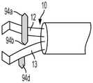
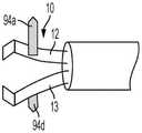
图9A、图9B、图9C示意性地图示了根据本公开的方面的每个臂具有多于一个锚定件和/或其中锚定件在彼此不同的方向上突出的夹。Figures 9A, 9B, 9C schematically illustrate that each arm has more than one anchor and/or a clip in which the anchors protrude in different directions from each other, according to aspects of the present disclosure.
图10A、图10B、图10C示意性地图示了根据本公开的方面的用于夹住患者的生物组织的夹,该夹具有两个锚定件。Figures 10A, 10B, 10C schematically illustrate a clip for clipping biological tissue of a patient, the clip having two anchors, in accordance with aspects of the present disclosure.
图11A、图11B和图11C示意性地图示了根据本公开的方面的具有被构造为旋转到夹的臂的平面中的锚定件的夹。11A, 11B, and 11C schematically illustrate a clip with anchors configured to rotate into the plane of the clip's arms, according to aspects of the present disclosure.
图12A和图12B示意性地图示了根据本公开的方面的具有臂的夹,该臂具有识别位于相应臂上的锚定件的位置的标记。12A and 12B schematically illustrate a clip having arms with markings identifying the location of anchors on the respective arms, according to aspects of the present disclosure.
图13A和图13B示意性地图示了根据本公开的方面的具有爪的夹,该爪具有缺口,或者其中该爪的宽度大于或小于锚定件的宽度使得当使用夹时可以更容易地观察到锚定件。Figures 13A and 13B schematically illustrate a clip with jaws having notches, or wherein the jaws have a width greater or less than the width of the anchor to allow easier viewing when the clip is in use, according to aspects of the present disclosure. to the anchor.
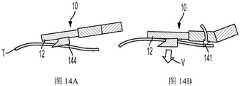
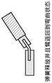
图14A和图14B示意性地图示了夹臂的侧视图,其中锚定件在第一臂的纵向的垂直方向上从该臂突出。在该示例中,锚定件呈允许夹垂直地附接在组织上的钩的形状。Figures 14A and 14B schematically illustrate side views of a clip arm with anchors protruding from the first arm in a direction perpendicular to the longitudinal direction of the arm. In this example, the anchors are in the shape of hooks that allow the clip to be attached vertically to tissue.
图15A和图15B示意性地图示了根据本公开的方面的夹的侧视图,该夹被构造为在夹附接到患者的组织之后从外科手术工具释放并且包括位于夹的臂上的弯曲构件。15A and 15B schematically illustrate side views of a clip configured to be released from a surgical tool after the clip is attached to a patient's tissue and including a flexure member on an arm of the clip according to aspects of the present disclosure .
图16A和图16B示意性地图示了根据本公开的方面的夹的侧视图,该夹被构造为包括位于夹的臂上的弯曲构件。16A and 16B schematically illustrate side views of a clip configured to include curved members on arms of the clip, according to aspects of the present disclosure.
图16C是图16A的夹臂的放大图。Figure 16C is an enlarged view of the clamp arm of Figure 16A.
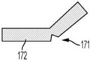
图17A示意性地图示了根据本公开的方面的夹的侧视图,该夹被构造为包括位于夹的臂上的弯曲构件和凹口。17A schematically illustrates a side view of a clip configured to include curved members and notches on arms of the clip, according to aspects of the present disclosure.
图18A和图18B示意性地图示了根据本公开的方面的具有臂的夹的侧视图,该臂具有通过接头铰接在一起的两部分。18A and 18B schematically illustrate side views of a clip with an arm having two parts hinged together by a joint in accordance with aspects of the present disclosure.
图19A和图19B示意性地图示了根据本公开的方面的具有臂的夹,该臂具有通过接头铰接在一起的两部分,其中臂可以锁定在弯曲状态。19A and 19B schematically illustrate a clip with an arm having two parts hinged together by a joint, wherein the arm can be locked in a bent state, according to aspects of the present disclosure.
图19C是图19B的夹的臂的放大图。Figure 19C is an enlarged view of the arms of the clip of Figure 19B.
图20A、图20B、图20C、图20D示意性地图示了根据本公开的方面的具有臂的夹的另一实施方式的侧视图,该臂具有通过接头铰接在一起的两部分。20A, 20B, 20C, 20D schematically illustrate side views of another embodiment of a clip with an arm having two parts hinged together by a joint in accordance with aspects of the present disclosure.
在所有附图中,为了清楚起见,适当地调整了各个组成元素的尺寸。为便于观察,在一些情况下,图中只有一些被命名的特征被标注附图标记。In all the drawings, the size of each constituent element is appropriately adjusted for clarity. For ease of viewing, in some cases only some of the named features in the figures are marked with reference numerals.
具体实施方式Detailed ways
本公开的夹可用于患者的治疗过程,诸如防止组织出血、闭合穿孔和止血和内伤缝合收缩、标记病变和牵引(粘膜抬高)以及其它外科手术。如本文所用的,术语“患者”包括任何和所有生物体并且包括术语“受试者”。患者可以是人或动物。The clips of the present disclosure can be used in patient procedures such as preventing tissue bleeding, closing perforations and hemostasis and suture retraction for internal trauma, marking lesions and traction (mucosal elevation), and other surgical procedures. As used herein, the term "patient" includes any and all organisms and includes the term "subject." The patient can be human or animal.
通常用于抓取患者组织的夹由夹操作工具致动。这种工具通过通常容纳在柔性管中的操作线致动夹,在柔性管中,通过操作工具的手柄,操作线可以在柔性管中纵向地前进和缩回。本文中对术语“远侧”的引用是指远离操作手柄的方向,而对术语“近侧”的引用是指朝向操作手柄的方向。诸如美国专利No.8,480,685和No.9,949,740中说明的那些夹操作工具可以与本公开的夹一起使用,并且各公开均通过引用全部合并于此。The clips typically used to grasp patient tissue are actuated by clip manipulation tools. Such tools actuate the clips by means of an operating wire typically housed in a flexible tube where the operating wire can be advanced and retracted longitudinally within the flexible tube by means of a handle of the operating tool. References herein to the term "distal" refer to the direction away from the operating handle, while references to the term "proximal" refer to the direction toward the operating handle. Clip handling tools such as those described in US Pat. Nos. 8,480,685 and 9,949,740, each of which is incorporated herein by reference in its entirety, may be used with the clips of the present disclosure.
将参照图1A至图20D说明根据本公开的夹的各种实施方式和方面。Various embodiments and aspects of clips according to the present disclosure will be described with reference to FIGS. 1A-20D .
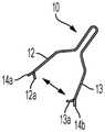
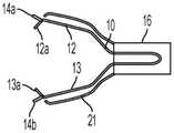
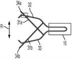
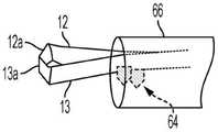
如图1A-图1D所示,用于夹住患者的生物组织的夹10具有第一臂12和第二臂13,第一臂12在第一臂12的远端具有第一爪12a,第二臂13在第二臂13的远端具有第二爪13a。如进一步图示的,第一爪12a和第二爪13a彼此面对,并且第一臂12和第二臂13被构造为在朝向彼此和远离彼此的反复方向(R)上移动以闭合和打开夹。第一爪和第二爪可以位于相同或大致相同的平面上,使得当臂闭合时,爪彼此接触。As shown in FIGS. 1A-1D , the
本公开的夹有利地包括从第一臂和/或第二臂突出的一个或多个锚定件。如本文所用的锚定件包括在以最小的力接触时可以附接到患者的组织的结构,并且可以包括例如突起、钩、倒钩、钉等。在除了第一臂和第二臂被构造为朝向彼此移动以闭合夹的方向之外的方向上,一个或多个锚定件从它们相应的臂突出。例如,锚定件可以在不同于爪的方向上或在与第一和第二臂限定的平面正交的方向上(在相对于臂的垂直方向上)突出,或者以在除了第一臂和第二臂被构造成朝向彼此移动以闭合夹的方向之外的任何其它方向上突出。The clips of the present disclosure advantageously include one or more anchors protruding from the first arm and/or the second arm. Anchors, as used herein, include structures that can be attached to a patient's tissue when contacted with minimal force, and can include, for example, protrusions, hooks, barbs, staples, and the like. One or more anchors protrude from their respective arms in directions other than the direction in which the first and second arms are configured to move toward each other to close the clip. For example, the anchors may protrude in a direction other than the jaws or in a direction orthogonal to the plane defined by the first and second arms (in a vertical direction relative to the arms), or in a direction other than the first arm and the second arm. The second arms are configured to protrude in any other direction than the direction in which they move toward each other to close the clip.
在本发明中,用于夹住患者的生物组织的夹10的形状并不限定于图1A所示的形状,也可以采用例如具有连结机构的夹(如图1E所示)或者多臂型的夹(如图1F所示)等的其它类型的夹。In the present invention, the shape of the
具体地,图1E示意性地图示了具有连结机构的夹。夹10具有第一臂12和第二臂13。第一臂12和第二臂13可以围绕由销轴9形成的公共枢轴旋转,以便打开和关闭它们。第一臂12和第二臂13上分别设置有导向槽8,第一臂12和第二臂13上的导向槽8相互部分重叠。夹10还包括引导销5,引导销5延伸穿过其重叠部分中的导向槽8。Specifically, Figure IE schematically illustrates a clip with a linking mechanism. The
图1F示意性地图示了具有多个臂的夹(图1F中作为参考示出了三臂夹,根据实际应用,夹10也可以具有三个以上的臂)。用于夹住患者的生物组织的夹10具有固定臂11和分别通过销轴9与固定臂11转动连接的两个活动臂(即第一臂12和第二臂13)。第一臂12在第一臂12的远端具有第一爪12a,第二臂13在第二臂13的远端具有第二爪13a。Figure IF schematically illustrates a clip with multiple arms (a three-arm clip is shown for reference in Figure IF, the
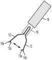
如图1A-图1F进一步图示,第一臂12包括位于第一臂12的外表面的在不同于第一爪12a的方向上突出的第一锚定件14a,并且第二臂13包括位于其外表面上的在不同于第二爪13a的方向上突出的第二锚定件14b。夹10可以从可以联接到柔性管18的管(本文也称为压管)16内展开。在操作期间,被朝向如图1C和图1D所示的打开的组织接收构造施力的臂12和13可以通过致动联接到夹的操作线(未示出)以使夹能在所述管中远近滑动来闭合。通过操作工具(未示出)的手柄,操作线可以在柔性管(未示出)中纵向地前进和缩回。通过使臂和爪朝向彼此和远离彼此地移动,远近滑动地移动夹来打开和闭合夹。在一些实施方式中,一旦夹缩回到压管中,夹就可以被锁定而不能打开。As further illustrated in FIGS. 1A-1F , the
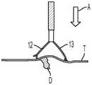
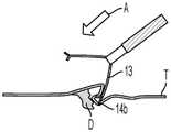
如图1C-图1D图示的,本公开的夹的优点在于即使当夹的接近(A)不垂直于组织时,例如图1C图示了垂直接近,而图1D图示了切向接近,夹仍可以附接到组织。在非垂直接近期间,位于臂13上的锚定件(14b)可以捕获病灶(D)附近的组织(T)。当在锚定件捕获组织之后闭合夹时,爪和臂可以提起组织,使得臂的爪可以更容易地抓住组织。此外,在锚定件捕获组织后,可以旋转夹以在锚定件附接到组织的情况下进一步将组织抓在臂的爪中。有利地,位于本公开的夹的臂的外表面上的一个或多个锚定件可以防止夹的臂的远端在切向接近组织期间(图1D)滑动。An advantage of the clips of the present disclosure, as illustrated in Figures 1C-1D, is that even when the clip's approach (A) is not perpendicular to the tissue, eg Figure 1C illustrates vertical approach and Figure ID illustrates tangential approach, The clip can still be attached to the tissue. Anchors (14b) on
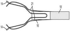
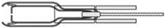
图2A至图6B图示了本公开的夹的不同方面以及减轻锚定件与夹工具或内窥镜的其它部分的接触的不同方式。例如,图2A-图2E示出了可以遮蔽夹的锚定件的覆盖件。在图2A-图2B中,覆盖件21附接到压管(管)16并从压管16向远侧延伸。夹10可以通过可滑动地缩回压管16中而闭合(图2B)。当夹缩回压管中时,覆盖件可以向远侧充分延伸以遮蔽位于臂的外表面的一个或多个锚定件。如图2B所示,当夹10缩回压管16中时,覆盖件21向远侧充分延伸以遮蔽锚定件14a和14b。2A-6B illustrate different aspects of the clips of the present disclosure and different ways of alleviating the contact of the anchor with the clip tool or other parts of the endoscope. For example, Figures 2A-2E illustrate a cover that can shield the anchor of the clip. In FIGS. 2A-2B , the
图2C-图2E图示了可以遮蔽夹的锚定件的覆盖件的不同附接位置。例如,图2C示出了附接到护套18的覆盖件21。图2D-图2E示出了覆盖件21如何附接到连接构件29或线27。图2D示出了锚定件14露出情况下的处于打开状态的夹,图2E示出了锚定件被覆盖件21遮蔽情况下的处于闭合状态的夹。不管附接的位置如何,当夹缩回压管中时,覆盖件向远侧充分延伸以遮蔽锚定件。覆盖件21可以由塑料或其它弹性材料或金属制成并且可以通过粘合剂或熔接来附接。Figures 2C-2E illustrate different attachment positions for a cover that can shield the anchor of the clip. For example, FIG. 2C shows
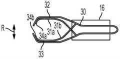
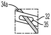
图3A-图3C和图4A-图4C示出了在夹打开之后可以突出通过夹的臂中的缝的柔性锚定件。如图3A所示,当夹处于闭合状态(图3A)时,锚定件34a和34b可以被夹30的第一臂32和第二臂33的内表面遮蔽。锚定件34a和34b分别通过柔性构件31a和31b连接到夹30。当夹30处于如图3B和图3C所示的打开状态时,锚定件34a突出通过夹30的第一臂32中的缝35。当夹30处于打开状态时,锚定件34b类似地突出通过第二臂33中的缝(为了方便起见未示出)。以此方式,可以在展开夹(诸如从压管16展开夹30)之前遮蔽锚定件。Figures 3A-3C and 4A-4C illustrate flexible anchors that can protrude through slits in the arms of the clip after the clip is opened. As shown in FIG. 3A , the
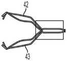
在独立的实施方式中,图4A-图4H示出了在夹打开之后可以突出通过夹的臂中的缝的柔性锚定件。特别地,当夹40朝向闭合状态移动(图4B-图4C)时,锚定件44a和44b可以分别朝向第一臂42和第二臂43缩回。锚定件44a和44b分别通过柔性构件41a和41b连接到夹40。当夹40处于如图4A图示的打开状态时,锚定件44a通过柔性构件41a突出通过夹40的第一臂42中的缝45。当夹40处于打开状态时,锚定件44b类似地突出通过第二臂43中的缝(为了方便起见未示出)。以此方式,当夹缩回压管16中时,可以将锚定件带向夹的臂。In separate embodiments, Figures 4A-4H illustrate flexible anchors that can protrude through slits in the arms of the clip after the clip is opened. In particular, anchors 44a and 44b may be retracted toward first and
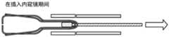
如图4D-图4H中进一步图示,当夹和柔性构件插入诸如内窥镜等的工具中时可以处于闭合状态(图4E和图4F)。由于夹臂和柔性构件被朝向打开状态施力,夹臂和柔性构件在离开工具的通道的操作中打开(图4D和图4G)。在操作中,连接到线(未示出)的近端的手柄(未示出)操作线(47)使夹(40)在压管(16)中缩回来闭合夹臂。特定夹装置可以包括连接构件(49)以从护套(18)接合和释放压管(图4H)。这种装置包括连接构件以从线接合和解除接合夹的远端。此外,连接构件可以包括内部接合和解除接合元件。柔性构件可以连接到线或连接构件并缩回压管中(图4H)。As further illustrated in Figures 4D-4H, the clip and flexible member may be in a closed state when inserted into a tool such as an endoscope (Figures 4E and 4F). As the jaws and flexible members are forced toward the open state, the jaws and flexible members open in operation out of the channel of the tool (FIGS. 4D and 4G). In operation, a handle (not shown) attached to the proximal end of the wire (not shown) operates the wire (47) to retract the clip (40) in the compression tube (16) to close the clip arms. Certain clip arrangements may include connecting members (49) to engage and release the compression tube from the sheath (18) (FIG. 4H). This device includes a connecting member to engage and disengage the distal end of the clip from the wire. Additionally, the connecting member may include internal engagement and disengagement elements. The flexible member can be attached to the wire or connecting member and retracted into the compression tube (FIG. 4H).
在独立的实施方式中,图5A和图5B示出了用于夹住患者的生物组织的夹50,夹50具有第一臂12和第二臂13,第一臂12在第一臂12的远端处具有第一爪12a,第二臂13在第二臂13的远端处具有第二爪13a。如进一步图示的,第一爪12a和第二爪13a彼此面对,并且第一臂12和第二臂13被构造为在朝向彼此和远离彼此的反复方向(R)上移动以闭合和打开夹。如图中进一步图示的,第一臂12包括在不同于第一爪12a的方向上从第一臂12突出的锚定件14a,第二臂13包括在不同于第二爪13a的方向上从第二臂13突出的第二锚定件14b。夹50可以从压管16内展开到打开状态(图5A)。当处于闭合状态(图5B)时,夹形成由锚定件的远端之间的距离限定的宽度(W),宽度(W)小于压管16的宽度或小于诸如内窥镜中的通道等的治疗工具(51)中的通道的宽度,使得从臂(14a、14b)突出的锚定件不接触或最小程度地接触通道。In a separate embodiment, FIGS. 5A and 5B show a
在另一实施方式中,图6A和图6B示出了具有第一臂12和第二臂13的夹,第一臂12在第一臂12的远端处具有第一爪12a,第二臂13在第二臂13的远端处具有第二爪13a。如进一步图示的,第一爪12a和第二爪13a彼此面对,并且第一臂12和第二臂13被构造为在朝向彼此的方向上移动以闭合夹。在该实施方式中,当臂闭合时,爪12a和13a接触。如图中进一步图示,夹包括位于第一臂12的锚定件64a并且包括位于第二臂13的锚定件64b,其中两个锚定件在与第一臂12和第二臂13形成的平面正交的方向上突出。压管66具有例如直径(D)的开口,开口足够大以当夹缩回压管中时允许锚定件进入管。图6B示出了当夹缩回压管中并且夹处于闭合状态时压管66中的锚定件64。In another embodiment, Figures 6A and 6B show a clip having a
应当注意,臂、爪和锚定件可以具有合适的形式,诸如线的形式(如在例如图1A至图1D中图示的实施方式中)或者诸如带的形式(如在例如图6A和图6B中图示的实施方式中)或者可以具有,诸如臂和爪中的一者呈带形式并且锚定件呈线形式的混合形式。It should be noted that the arms, claws and anchors may have suitable forms, such as in the form of wires (as in, for example, the embodiments illustrated in Figures 1A-1D) or in the form of strips (as in, eg, Figures 6A and 6A ). 6B) or may have a hybrid form such as one of the arms and jaws in the form of a strap and the anchor in the form of a wire.
图7A至图8C图示了夹的臂上可以包括的锚定件的其它方面。特别地,图7A-图7C示出了用于抓住患者的生物组织(T)的夹70,夹70具有第一臂12和第二臂13,第一臂12在第一臂12的远端处具有第一爪12a,第二臂13在第二臂13的远端处具有第二爪13a。第一爪12a和第二爪13a彼此面对。如进一步图示的,第一臂12包括位于第一臂12的外表面的第一锚定件74a,第一锚定件74a在不同于第一爪12a的方向上突出,第二臂13包括位于第二臂13的外表面的第二锚定件74b,第二锚定件74b在不同于第二爪13a的方向上突出。在该示例中,第一锚定件74a和第二锚定件74b由生物可吸收材料制成。以此方式,在锚定件附接到组织(T)之后,它们最终可以溶解在组织中并从夹去除(图7C)。这种由生物可吸收性材料制成的锚定件最初可以通过诸如生物可吸收性粘合剂的粘合剂附接到夹臂。7A-8C illustrate other aspects of anchors that may be included on the arms of the clip. In particular, FIGS. 7A-7C show a
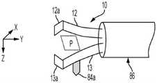
图8A-图11C示出了在与第一臂和第二臂限定的平面正交的方向上突出的锚定件。特别地,图8A和图10C示出了用于抓住患者的生物组织(T)的夹10,夹10具有第一臂12和第二臂13,第一臂12在第一臂12的远端处具有第一爪12a,第二臂13在第二臂13的远端处具有第二爪13a,其中第一爪12a和第二爪13a彼此面对,并且第一臂12和第二臂13被构造为朝向彼此移动以闭合夹。在图8A中,第一臂12包括第一锚定件84a,其中锚定件84a在与第一臂和第二臂限定的平面(P)正交的方向上从第一臂突出。如图所示,臂可以形成具有x坐标和y坐标的平面,并且锚定件可以沿z坐标突出。在图10A中,第一臂12包括第一锚定件104a,其中锚定件104a在与第一臂和第二臂限定的平面正交的方向上从第一臂突出,第二臂13包括第二锚定件104b,其中锚定件104b在与第一臂和第二臂限定的平面正交的方向上从第二臂突出。锚定件104a和104b从由臂限定的平面沿相反方向突出。一个或多个锚定件在与第一臂和第二臂限定的平面正交的方向上突出的构造有利地可以在臂彼此接近时使正交方向上的锚定件(图8B、图10B)捕获的组织提高(分别是图8C中的81、图10C中的101),这有助于将组织抓在臂中。8A-11C illustrate the anchors projecting in a direction normal to the plane defined by the first and second arms. In particular, FIGS. 8A and 10C show a
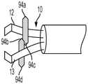
图9A-图9C图示了每个臂具有多于一个锚定件和/或其中锚定件在彼此不同的方向上突出的夹。特别地,图9A示出了具有两个锚定件的第一臂12。第一锚定件94a在与第一臂12和第二臂限定的平面正交的方向上从第一臂突出,第二锚定件94c在与第一臂12和第二臂限定的平面正交但与第一锚定件94a相反的方向上从第一臂突出。第二臂13也具有两个锚定件。第三锚定件94b在与第一臂和第二臂13限定的平面正交的方向上从第二臂突出,第四锚定件94d在与第一臂和第二臂13限定的平面正交但与第三锚定件94b相反的方向上从第二臂突出。图9B示出了具有两个锚定件(94a、94b)的第一臂12和具有第三锚定件(94d)的第二臂13。图9C示出了夹的各臂具有一个锚定件(94a、94d),但是所述锚定件从臂限定的平面沿相反方向突出。9A-9C illustrate each arm having more than one anchor and/or a clip in which the anchors protrude in different directions from each other. In particular, Figure 9A shows the
图11A-图11B以及图11C图示了被构造成当夹缩回压管中时旋转到臂的平面中的锚定件。例如并参照图11A-图11B,第一和第二锚定件(114a、114b)通过例如销(111a、111b)等的结构附接到相应的第一和第二臂(12、13),这允许当夹缩回压管116中并且压管的边缘接触锚定件时锚定件朝向臂限定的平面旋转(119)。11A-11B and 11C illustrate the anchor configured to rotate into the plane of the arm when the clip is retracted into the compression tube. For example and with reference to Figures 11A-11B, the first and second anchors (114a, 114b) are attached to the respective first and second arms (12, 13) by structures such as pins (111a, 111b), etc., This allows the anchor to rotate towards the plane defined by the arms when the clip is retracted into the
图11C示出了被构造为当臂可滑动地缩回压管或从压管伸出时使锚定件旋转到夹的臂的平面中的另一结构。如图所示,锚定件114与夹臂13形成一体并被施力成打开状态,但在压管116中缩回时被施力成闭合状态。通过该结构,不需要销来使夹的臂包括当夹缩回压管116中时可以朝向臂限定的平面旋转的锚定件。替代地,锚定件具有弹簧打开施力装置并且在从管向远侧延伸时从压管弹出。Figure 11C shows another configuration configured to rotate the anchor into the plane of the arms of the clip when the arms are slidably retracted into or extended from the compression tube. As shown, the anchors 114 are integral with the
图12A-图13B图示了具有在使用夹时可以更容易地识别的锚定件的夹。例如,图12A和图12B示出了在各个臂上具有标记121的第一臂12和第二臂13,标记121识别位于各个臂上的第一锚定件124a或124b的位置。以此方式,当使用者不容易看到锚定件时(诸如当锚定件被卡在组织(T)中时),使用者可以通过位于相应的第一臂或第二臂上的标记(121a、121b)来识别锚定件的位置。位于夹的臂上的标记121可以由臂上的荧光标记、颜色、符号、纹理(诸如粗糙度等)或锚定件位置处的臂上的等效物引起。12A-13B illustrate a clip with anchors that can be more easily identified when the clip is in use. For example, Figures 12A and 12B show the
图13A和图13B图示了具有爪的夹,爪具有缺口,或者其中爪的宽度大于或小于锚定件的宽度,使得在使用夹时可以更容易地观察到锚定件。例如,图13A-图13B示出了具有第一和第二臂(12、13)的夹10,第一和第二臂(12、13)具有第一和第二爪(12a、13a),其中第一和第二锚定件的宽度小于爪的宽度(134a、134b)或大于爪的宽度(134c、134d),以便于在使用时观察锚定件。此外或可替代地,爪可以包括缺口以便于观察锚定件。图13A示出了具有便于观察锚定件134a的缺口的第一爪132a以及具有便于观察锚定件134b的缺口的第二爪133a。Figures 13A and 13B illustrate a clip with claws that have notches, or where the width of the claws is greater or less than the width of the anchor so that the anchor can be more easily seen when the clip is in use. For example, Figures 13A-13B show a
图14A-图20D示意性地图示了根据本公开的夹臂,当夹与组织相切时,夹臂可以进一步有利地对组织施加垂直力,并且可以弯曲以便于将多个夹彼此非常接近地放置。例如,图14A和图14B示出了夹10的侧视图,该图示出了第一臂12,其中锚定件144在第一臂的纵向的垂直方向上从第一臂12突出。在该示例中,锚定件144呈钩状并且处于与夹的第一臂和第二臂限定的平面正交的方向上,这允许夹被垂直地放置在组织上。在锚定件144附接到组织(T)之后,夹可以旋转141,旋转141在组织上产生垂直力。本公开中阐述的夹上的锚定件的另一优点是这种夹可以牢固地压在粘膜上,允许更多的组织插入爪之间并且更多的组织被夹抓住。FIGS. 14A-20D schematically illustrate clip arms according to the present disclosure, which can further advantageously apply a vertical force to tissue when the clips are tangential to tissue, and can flex to facilitate placing multiple clips in close proximity to each other. place. For example, Figures 14A and 14B show side views of the
在某些实施方式中,本公开的夹可从外科手术工具断开并夹在患者的组织上。为了便于将夹彼此相邻地放置,夹臂可以被构造为弯曲。如图15A和图15B的侧视图所示,夹可以被构造为在夹附接到患者的组织(150a)之后从外科手术工具释放。然而,由于夹的近端和附接到夹的近端的任何构件(诸如压管156),第二夹(150b)的放置有点受限。在该示例中,夹150c具有第一臂152和第二臂(未示出)以及压管156,其中第一锚定件154位于第一臂152。如图所示,夹150c包括沿着夹的弯曲部分或构件151。以此方式,当附接到患者的组织时,具有锚定件和被构造为弯曲的臂(150c和150d)的夹可以更容易彼此相邻地放置。In certain embodiments, the clips of the present disclosure can be disconnected from a surgical tool and clamped to a patient's tissue. To facilitate placing the clips adjacent to each other, the clip arms may be configured to be curved. As shown in the side views of Figures 15A and 15B, the clip may be configured to be released from the surgical tool after the clip is attached to the patient's tissue (150a). However, placement of the second clip (150b) is somewhat limited due to the proximal end of the clip and any members attached to the proximal end of the clip, such as
图16A-图20D示意性地图示了夹臂被构造成弯曲的各种结构特征。例如,图16A和图16C示出了具有第一臂162的夹160,第一臂162包括具有高弹性的构件161。夹160的第二臂也具有高弹性构件,但未在图16A至图16C的侧视图中示出。夹臂被施力为处于弯曲状态,使得当夹在压管166中被加载时,夹臂处于伸直姿态(L),但是当从压管166展开时,夹臂162如卸载状态(U)所示地弯曲。作为弹性构件的替代或附加,夹臂可具有一个或多个弹簧以对处于弯曲状态的夹臂施力。当这种夹被放置在内窥镜(165)的通道中时,臂将处于伸直姿态,但是当从通道展开时,臂将弯曲(图16B)。在图17A中,夹臂172包括当臂弯曲时可以减轻应力的凹口171。16A-20D schematically illustrate various structural features in which the clip arms are configured to bend. For example, FIGS. 16A and 16C show a
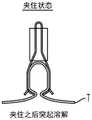
可用于将本公开的夹的臂构造为弯曲的其它结构图示于图18A-图20D。在图18A和图18B中,夹臂182包括通过接头181铰接在一起的两部分(182a、182b)。图19A-图19C图示了被构造为弯曲的夹的臂的锁定构造。图19A示出了夹臂192,其包括通过接头191连接的两个铰接部分(192a、192b)。部分192b可以具有销195a,当臂向弯曲位置移动时,销195a沿着槽195b移动。销可以越过槽195b中的突起195c以将臂锁定在弯曲状态。图19B-图19C示出了包括通过接头191连接的两个铰接部分(195a、195b)的夹臂195,其中臂195的在内部分195a具有凹面197a,臂195的在外部分195b具有凸面197b,使得当臂195的在外部分195b旋转以将臂定位在弯曲状态时,凹面197a配合在凸面197b中,如臂195的截面图所示。Other structures that may be used to configure the arms of the clips of the present disclosure to be curved are illustrated in Figures 18A-20D. In Figures 18A and 18B, the clamp arm 182 comprises two parts (182a, 182b) hinged together by a joint 181 . 19A-19C illustrate a locking configuration of an arm configured as a curved clip. FIG. 19A shows a
图20A-图20D图示了通过弹簧铰接在一起的夹臂。在图20A中,臂202包括通过弹簧201连接在一起的两部分(202a、202b)。夹臂被施力为处于弯曲状态,使得当夹在压管206中被加载时,夹臂处于伸直姿态(L),但是当从压管206展开时,夹臂202弯曲,如图20B中的卸载状态(U)所示。当这种夹被放置在内窥镜(205)的通道中时,夹的臂将处于伸直姿态,但是当从通道展开时,臂将弯曲(图20C和图20D)。20A-20D illustrate the clamp arms hinged together by springs. In FIG. 20A , the
在其它示例中,夹臂可以由形状记忆合金(诸如镍钛合金)制成,并且基于应力状态或温度而处于伸直或弯曲构造。In other examples, the clip arms may be made of a shape memory alloy, such as Nitinol, and be in a straightened or bent configuration based on stress state or temperature.
虽然已参照本发明的具体实施方式详细说明了要求保护的发明,但对本领域普通技术人员来说显而易见的是,在不脱离本发明的精神和范围的情况下,可以对要求保护的发明进行各种改变和修改。因此,例如,仅使用常规实验,本领域技术人员将识别到或能够确定本文说明的具体物质和过程的许多等价物。这种等价物被认为处于本发明的范围内,并且被所附方案覆盖。While the claimed invention has been described in detail with reference to specific embodiments of the invention, it will be apparent to those of ordinary skill in the art that various modifications of the claimed invention can be made without departing from the spirit and scope of the invention. changes and modifications. Thus, for example, those skilled in the art will recognize, or be able to ascertain using no more than routine experimentation, many equivalents to the specific materials and processes described herein. Such equivalents are considered to be within the scope of the present invention and are covered by the appended proposals.
Claims (16)
Translated fromChinesePriority Applications (1)
| Application Number | Priority Date | Filing Date | Title |
|---|---|---|---|
| CN202411224240.XACN119112284A (en) | 2020-10-16 | 2021-10-12 | Clips for endoscopes |
Applications Claiming Priority (2)
| Application Number | Priority Date | Filing Date | Title |
|---|---|---|---|
| US202063092981P | 2020-10-16 | 2020-10-16 | |
| US63/092,981 | 2020-10-16 |
Related Child Applications (1)
| Application Number | Title | Priority Date | Filing Date |
|---|---|---|---|
| CN202411224240.XADivisionCN119112284A (en) | 2020-10-16 | 2021-10-12 | Clips for endoscopes |
Publications (2)
| Publication Number | Publication Date |
|---|---|
| CN114376655Atrue CN114376655A (en) | 2022-04-22 |
| CN114376655B CN114376655B (en) | 2024-08-30 |
Family
ID=78085849
Family Applications (3)
| Application Number | Title | Priority Date | Filing Date |
|---|---|---|---|
| CN202111181510.XAPendingCN114376654A (en) | 2020-10-16 | 2021-10-11 | Bendable clip device |
| CN202411224240.XAPendingCN119112284A (en) | 2020-10-16 | 2021-10-12 | Clips for endoscopes |
| CN202111186087.2AActiveCN114376655B (en) | 2020-10-16 | 2021-10-12 | Clips for endoscopes |
Family Applications Before (2)
| Application Number | Title | Priority Date | Filing Date |
|---|---|---|---|
| CN202111181510.XAPendingCN114376654A (en) | 2020-10-16 | 2021-10-11 | Bendable clip device |
| CN202411224240.XAPendingCN119112284A (en) | 2020-10-16 | 2021-10-12 | Clips for endoscopes |
Country Status (5)
| Country | Link |
|---|---|
| US (4) | US12114865B2 (en) |
| EP (3) | EP3984471A1 (en) |
| JP (4) | JP7553420B2 (en) |
| CN (3) | CN114376654A (en) |
| WO (1) | WO2022080474A1 (en) |
Families Citing this family (3)
| Publication number | Priority date | Publication date | Assignee | Title |
|---|---|---|---|---|
| WO2024128084A1 (en)* | 2022-12-16 | 2024-06-20 | 日本ゼオン株式会社 | Endoscopic suture ligation tool |
| WO2024162800A1 (en)* | 2023-02-02 | 2024-08-08 | 고려대학교 산학협력단 | Endoscope clip using shape memory alloy |
| WO2024257386A1 (en)* | 2023-06-16 | 2024-12-19 | オリンパスメディカルシステムズ株式会社 | Clip unit |
Citations (10)
| Publication number | Priority date | Publication date | Assignee | Title |
|---|---|---|---|---|
| US20050251160A1 (en)* | 2004-05-07 | 2005-11-10 | Usgi Medical Inc. | Apparatus for manipulating and securing tissue |
| CN101588760A (en)* | 2007-01-26 | 2009-11-25 | 奥林巴斯医疗株式会社 | Gripping device and gripping tool |
| US20120041455A1 (en)* | 2010-08-10 | 2012-02-16 | Cook Medical Technologies Llc | Clip devices and methods of delivery and deployment |
| US20130226199A1 (en)* | 2012-02-28 | 2013-08-29 | Boston Scientific Scimed, Inc. | Omnidirectional closure clip |
| WO2016028898A2 (en)* | 2014-08-21 | 2016-02-25 | Boston Scientific Scimed, Inc. | Anchors and cinching for tissue opposition |
| JP2017176335A (en)* | 2016-03-29 | 2017-10-05 | 小林 真 | Clip unit for ligation device |
| CN108567462A (en)* | 2017-03-07 | 2018-09-25 | 祝建红 | Hemostatic clamp |
| US20190150929A1 (en)* | 2017-11-15 | 2019-05-23 | United States Endoscopy Group, Inc. | Clip and clip assembly |
| WO2019207585A1 (en)* | 2018-04-25 | 2019-10-31 | Endomatic Ltd. | Suturing clip |
| WO2020095428A1 (en)* | 2018-11-09 | 2020-05-14 | オリンパス株式会社 | Clip unit and endoscope clip |
Family Cites Families (58)
| Publication number | Priority date | Publication date | Assignee | Title |
|---|---|---|---|---|
| US5409498A (en)* | 1992-11-05 | 1995-04-25 | Ethicon, Inc. | Rotatable articulating endoscopic fastening instrument |
| US5620452A (en) | 1994-12-22 | 1997-04-15 | Yoon; Inbae | Surgical clip with ductile tissue penetrating members |
| US5904647A (en) | 1996-10-08 | 1999-05-18 | Asahi Kogyo Kabushiki Kaisha | Treatment accessories for an endoscope |
| US6398791B1 (en)* | 1999-06-11 | 2002-06-04 | Scimed Life Systems Inc | Variable composite sheath with interrupted sections |
| JP4472217B2 (en) | 2000-10-16 | 2010-06-02 | オリンパス株式会社 | Biological tissue clip device |
| US20020138086A1 (en) | 2000-12-06 | 2002-09-26 | Robert Sixto | Surgical clips particularly useful in the endoluminal treatment of gastroesophageal reflux disease (GERD) |
| US6716226B2 (en) | 2001-06-25 | 2004-04-06 | Inscope Development, Llc | Surgical clip |
| US6544274B2 (en) | 2001-05-02 | 2003-04-08 | Novare Surgical Systems, Inc. | Clamp having bendable shaft |
| US7094245B2 (en) | 2001-10-05 | 2006-08-22 | Scimed Life Systems, Inc. | Device and method for through the scope endoscopic hemostatic clipping |
| JP4109030B2 (en)* | 2002-07-19 | 2008-06-25 | オリンパス株式会社 | Biological tissue clip device |
| US7727247B2 (en)* | 2002-08-21 | 2010-06-01 | Olympus Corporation | Living tissue ligation device |
| JP4109069B2 (en)* | 2002-10-01 | 2008-06-25 | オリンパス株式会社 | Biological tissue ligation device |
| JP4412943B2 (en)* | 2003-08-20 | 2010-02-10 | Hoya株式会社 | Endoscopic clip device |
| US7052489B2 (en)* | 2003-12-05 | 2006-05-30 | Scimed Life Systems, Inc. | Medical device with deflecting shaft and related methods of manufacture and use |
| WO2006062019A1 (en) | 2004-12-07 | 2006-06-15 | Olympus Corporation | Treatment instrument for endoscope and cartridge in which treatment instrument is received |
| JP2006158668A (en)* | 2004-12-07 | 2006-06-22 | Olympus Corp | Treatment instrument for endoscope |
| JP2006296781A (en)* | 2005-04-21 | 2006-11-02 | Olympus Medical Systems Corp | Endoscopic treatment tool |
| US7963288B2 (en) | 2005-05-03 | 2011-06-21 | Hansen Medical, Inc. | Robotic catheter system |
| JP4935040B2 (en)* | 2005-09-30 | 2012-05-23 | 住友ベークライト株式会社 | Endoscope clip |
| JP2007136128A (en) | 2005-11-17 | 2007-06-07 | River Seiko:Kk | Endoscopic clip device |
| JP4716513B2 (en)* | 2006-11-09 | 2011-07-06 | Hoya株式会社 | Endoscopic clip device |
| WO2008112942A2 (en) | 2007-03-13 | 2008-09-18 | Harris Peter S | Methods and devices for reducing gastric volume |
| US8162959B2 (en) | 2007-05-03 | 2012-04-24 | Boston Scientific Scimed, Inc. | Single stage hemostasis clipping device |
| US9393093B2 (en)* | 2008-02-18 | 2016-07-19 | Covidien Lp | Clip for implant deployment device |
| EP3061413B1 (en)* | 2008-06-19 | 2022-01-19 | Boston Scientific Scimed, Inc. | Tissue clipping apparatus |
| US20090318937A1 (en)* | 2008-06-24 | 2009-12-24 | Fujifilm Corporation | Clip coupling method and multiple clip package |
| JP2010213990A (en)* | 2009-03-18 | 2010-09-30 | Fujifilm Corp | Connection clip package, and clip loading method |
| US8652153B2 (en)* | 2010-01-11 | 2014-02-18 | Anulex Technologies, Inc. | Intervertebral disc annulus repair system and bone anchor delivery tool |
| US8403945B2 (en)* | 2010-02-25 | 2013-03-26 | Covidien Lp | Articulating endoscopic surgical clip applier |
| US20110319710A1 (en)* | 2010-06-28 | 2011-12-29 | Molly Phillips-Hungerford | Scope protection for endoscopic devices |
| US8968337B2 (en)* | 2010-07-28 | 2015-03-03 | Covidien Lp | Articulating clip applier |
| JP2012065835A (en)* | 2010-09-22 | 2012-04-05 | Fujifilm Corp | Ligature device and clip unit used therein |
| US20120078372A1 (en) | 2010-09-23 | 2012-03-29 | Thomas Gamache | Novel implant inserter having a laterally-extending dovetail engagement feature |
| JP5781347B2 (en) | 2011-03-28 | 2015-09-24 | 日本ゼオン株式会社 | Endoscopic treatment tool |
| US10154842B2 (en)* | 2011-05-04 | 2018-12-18 | Boston Scientific Scimed, Inc. | Through the scope tension member release clip |
| US20130023925A1 (en)* | 2011-07-20 | 2013-01-24 | Tyco Healthcare Group Lp | Articulating Surgical Apparatus |
| US20130158566A1 (en) | 2011-12-15 | 2013-06-20 | Boston Scientific Scimed, Inc. | Rotational mechanism for endoscopic devices |
| US8992547B2 (en)* | 2012-03-21 | 2015-03-31 | Ethicon Endo-Surgery, Inc. | Methods and devices for creating tissue plications |
| JP2013255756A (en) | 2012-06-14 | 2013-12-26 | Fujifilm Corp | Treatment instrument for endoscope |
| JP5750619B2 (en) | 2013-05-07 | 2015-07-22 | オリンパス株式会社 | Clip unit |
| WO2014201563A1 (en)* | 2013-06-18 | 2014-12-24 | The Hospital For Sick Children | Tissue gripping device |
| JP6294016B2 (en)* | 2013-06-28 | 2018-03-14 | 日本ゼオン株式会社 | Endoscope clip |
| US9427232B2 (en)* | 2013-11-08 | 2016-08-30 | C.R. Bard, Inc. | Surgical fastener |
| JP6700572B2 (en)* | 2015-01-08 | 2020-05-27 | 日本ゼオン株式会社 | Clip device for endoscope |
| FR3032607B1 (en)* | 2015-02-13 | 2020-10-23 | Institut Hospitalo Univ De Chirurgie Mini Invasive Guidee Par Limage | SURGICAL CLIP PRESENTING TWO MOBILE BRANCHES CONNECTED BY A CROSS-LINK ZONE |
| JP2017192513A (en)* | 2016-04-19 | 2017-10-26 | 株式会社新興セルビック | Method for producing synthetic resin blood vessel clip and synthetic resin blood vessel clip |
| US20170340443A1 (en)* | 2016-05-24 | 2017-11-30 | Edwards Lifesciences Corporation | Posterior mitral valve leaflet approximation |
| WO2017212332A1 (en) | 2016-06-06 | 2017-12-14 | 3Nt Medical Ltd. | Modular body cavity access system |
| JP2018061672A (en)* | 2016-10-12 | 2018-04-19 | 日本ゼオン株式会社 | Indwelling clip |
| CA3031692C (en)* | 2016-11-22 | 2021-01-19 | Boston Scientific Limited | Hemostasis reloadable clip release mechanism |
| WO2019008632A1 (en)* | 2017-07-03 | 2019-01-10 | オリンパス株式会社 | Control device, treatment system, and treatment tool |
| CN111727017A (en)* | 2018-03-07 | 2020-09-29 | 富士胶片株式会社 | Treatment tool, endoscope device, endoscope system, and treatment method |
| EP3777718B1 (en)* | 2018-03-30 | 2025-03-05 | Zeon Corporation | Indwelling clip |
| US11033279B2 (en)* | 2018-04-24 | 2021-06-15 | Covidien Lp | Ligation clip with retention features |
| CN210077721U (en)* | 2018-12-14 | 2020-02-18 | 杭州市第一人民医院 | Steerable bending biopsy forceps |
| US11076862B2 (en)* | 2018-12-28 | 2021-08-03 | Olympus Corporation | Clip unit, medical instrument, and attaching method of medical instrument |
| CN118986456A (en) | 2018-12-28 | 2024-11-22 | 奥林巴斯株式会社 | Ligature device |
| CN113613567A (en)* | 2019-03-18 | 2021-11-05 | 国立大学法人熊本大学 | Fixing clamp for residual end of organ excision part |
- 2021
- 2021-10-07JPJP2021165771Apatent/JP7553420B2/enactiveActive
- 2021-10-07EPEP21201423.7Apatent/EP3984471A1/enactivePending
- 2021-10-07JPJP2021165768Apatent/JP7426364B2/enactiveActive
- 2021-10-08EPEP25180708.7Apatent/EP4588446A3/enactivePending
- 2021-10-08EPEP21201671.1Apatent/EP3984472B1/enactiveActive
- 2021-10-08WOPCT/JP2021/038151patent/WO2022080474A1/ennot_activeCeased
- 2021-10-11USUS17/498,062patent/US12114865B2/enactiveActive
- 2021-10-11CNCN202111181510.XApatent/CN114376654A/enactivePending
- 2021-10-11USUS17/498,064patent/US11931043B2/enactiveActive
- 2021-10-12CNCN202411224240.XApatent/CN119112284A/enactivePending
- 2021-10-12CNCN202111186087.2Apatent/CN114376655B/enactiveActive
- 2023
- 2023-05-15JPJP2023080358Apatent/JP2023091094A/enactivePending
- 2024
- 2024-01-12USUS18/411,596patent/US20240148389A1/enactivePending
- 2024-01-22JPJP2024007521Apatent/JP2024032823A/enactivePending
- 2024-08-21USUS18/810,632patent/US20240407788A1/enactivePending
Patent Citations (11)
| Publication number | Priority date | Publication date | Assignee | Title |
|---|---|---|---|---|
| US20050251160A1 (en)* | 2004-05-07 | 2005-11-10 | Usgi Medical Inc. | Apparatus for manipulating and securing tissue |
| CN101588760A (en)* | 2007-01-26 | 2009-11-25 | 奥林巴斯医疗株式会社 | Gripping device and gripping tool |
| US20120041455A1 (en)* | 2010-08-10 | 2012-02-16 | Cook Medical Technologies Llc | Clip devices and methods of delivery and deployment |
| US20130226199A1 (en)* | 2012-02-28 | 2013-08-29 | Boston Scientific Scimed, Inc. | Omnidirectional closure clip |
| WO2016028898A2 (en)* | 2014-08-21 | 2016-02-25 | Boston Scientific Scimed, Inc. | Anchors and cinching for tissue opposition |
| US20160051252A1 (en)* | 2014-08-21 | 2016-02-25 | Boston Scientific Scimed, Inc. | Anchors and cinching for tissue opposition |
| JP2017176335A (en)* | 2016-03-29 | 2017-10-05 | 小林 真 | Clip unit for ligation device |
| CN108567462A (en)* | 2017-03-07 | 2018-09-25 | 祝建红 | Hemostatic clamp |
| US20190150929A1 (en)* | 2017-11-15 | 2019-05-23 | United States Endoscopy Group, Inc. | Clip and clip assembly |
| WO2019207585A1 (en)* | 2018-04-25 | 2019-10-31 | Endomatic Ltd. | Suturing clip |
| WO2020095428A1 (en)* | 2018-11-09 | 2020-05-14 | オリンパス株式会社 | Clip unit and endoscope clip |
Also Published As
| Publication number | Publication date |
|---|---|
| US20240407788A1 (en) | 2024-12-12 |
| US20220117604A1 (en) | 2022-04-21 |
| EP4588446A3 (en) | 2025-09-10 |
| CN119112284A (en) | 2024-12-13 |
| US12114865B2 (en) | 2024-10-15 |
| JP2024032823A (en) | 2024-03-12 |
| EP3984472B1 (en) | 2025-07-09 |
| CN114376655B (en) | 2024-08-30 |
| JP7553420B2 (en) | 2024-09-18 |
| EP3984472A1 (en) | 2022-04-20 |
| WO2022080474A1 (en) | 2022-04-21 |
| JP2023091094A (en) | 2023-06-29 |
| EP3984471A1 (en) | 2022-04-20 |
| WO2022080474A8 (en) | 2022-06-09 |
| US20220117605A1 (en) | 2022-04-21 |
| CN114376654A (en) | 2022-04-22 |
| JP2022066159A (en) | 2022-04-28 |
| JP7426364B2 (en) | 2024-02-01 |
| US20240148389A1 (en) | 2024-05-09 |
| JP2022066160A (en) | 2022-04-28 |
| US11931043B2 (en) | 2024-03-19 |
| EP4588446A2 (en) | 2025-07-23 |
Similar Documents
| Publication | Publication Date | Title |
|---|---|---|
| CN114376655B (en) | Clips for endoscopes | |
| US12310589B2 (en) | Devices for approximating tissue and related methods of use | |
| AU2002320128B2 (en) | Surgical clip | |
| ES2629215T3 (en) | Endoscopic surgical device for tobacco bag suture | |
| EP3679867B1 (en) | Hemostatic clip with needle passer | |
| US20040193189A1 (en) | Passive surgical clip | |
| US11877747B2 (en) | Wide hemostasis clip | |
| US11129623B2 (en) | Dual support jaw design | |
| JP2022522472A (en) | Deployment of hemostatic clips | |
| WO2019109029A1 (en) | Rotatable endoscopic clip with folding prongs | |
| JP2007097663A (en) | Clip for endoscope | |
| JP2025516054A (en) | Wedgelock Needle Holder | |
| CN115209817A (en) | Needle holder for endoscope and endoscopic suturing method |
Legal Events
| Date | Code | Title | Description |
|---|---|---|---|
| PB01 | Publication | ||
| PB01 | Publication | ||
| SE01 | Entry into force of request for substantive examination | ||
| SE01 | Entry into force of request for substantive examination | ||
| GR01 | Patent grant | ||
| GR01 | Patent grant |