CN114376272A - Atomizing component and method of making the same - Google Patents
Atomizing component and method of making the sameDownload PDFInfo
- Publication number
- CN114376272A CN114376272ACN202210025354.6ACN202210025354ACN114376272ACN 114376272 ACN114376272 ACN 114376272ACN 202210025354 ACN202210025354 ACN 202210025354ACN 114376272 ACN114376272 ACN 114376272A
- Authority
- CN
- China
- Prior art keywords
- conductive
- liquid
- outlet
- pin
- cotton block
- Prior art date
- Legal status (The legal status is an assumption and is not a legal conclusion. Google has not performed a legal analysis and makes no representation as to the accuracy of the status listed.)
- Granted
Links
Images


Classifications
- A—HUMAN NECESSITIES
- A24—TOBACCO; CIGARS; CIGARETTES; SIMULATED SMOKING DEVICES; SMOKERS' REQUISITES
- A24F—SMOKERS' REQUISITES; MATCH BOXES; SIMULATED SMOKING DEVICES
- A24F40/00—Electrically operated smoking devices; Component parts thereof; Manufacture thereof; Maintenance or testing thereof; Charging means specially adapted therefor
- A24F40/40—Constructional details, e.g. connection of cartridges and battery parts
- A24F40/44—Wicks
- A—HUMAN NECESSITIES
- A24—TOBACCO; CIGARS; CIGARETTES; SIMULATED SMOKING DEVICES; SMOKERS' REQUISITES
- A24F—SMOKERS' REQUISITES; MATCH BOXES; SIMULATED SMOKING DEVICES
- A24F40/00—Electrically operated smoking devices; Component parts thereof; Manufacture thereof; Maintenance or testing thereof; Charging means specially adapted therefor
- A24F40/40—Constructional details, e.g. connection of cartridges and battery parts
- A24F40/46—Shape or structure of electric heating means
- A—HUMAN NECESSITIES
- A24—TOBACCO; CIGARS; CIGARETTES; SIMULATED SMOKING DEVICES; SMOKERS' REQUISITES
- A24F—SMOKERS' REQUISITES; MATCH BOXES; SIMULATED SMOKING DEVICES
- A24F40/00—Electrically operated smoking devices; Component parts thereof; Manufacture thereof; Maintenance or testing thereof; Charging means specially adapted therefor
- A24F40/40—Constructional details, e.g. connection of cartridges and battery parts
- A24F40/48—Fluid transfer means, e.g. pumps
- A—HUMAN NECESSITIES
- A24—TOBACCO; CIGARS; CIGARETTES; SIMULATED SMOKING DEVICES; SMOKERS' REQUISITES
- A24F—SMOKERS' REQUISITES; MATCH BOXES; SIMULATED SMOKING DEVICES
- A24F40/00—Electrically operated smoking devices; Component parts thereof; Manufacture thereof; Maintenance or testing thereof; Charging means specially adapted therefor
- A24F40/70—Manufacture
Landscapes
- Electrostatic Spraying Apparatus (AREA)
Abstract
Description
Translated fromChinese技术领域technical field
本发明涉及雾化设备技术领域,尤其涉及一种雾化组件及其制作方法。The invention relates to the technical field of atomization equipment, in particular to an atomization component and a manufacturing method thereof.
背景技术Background technique
目前电子烟作为烟草的替代品,深受广大吸烟者的喜爱,电子烟的本质是一种气溶胶发生装置,主要由主机和雾化器构成,雾化器用于对烟油进行雾化,并供雾化后的烟油与空气进行混合以供用户吸食,而主机用于为雾化器提供电源。At present, as a substitute for tobacco, electronic cigarettes are deeply loved by smokers. The essence of electronic cigarettes is an aerosol generating device, which is mainly composed of a host and an atomizer. The atomized e-liquid is mixed with air for users to smoke, and the host is used to provide power for the atomizer.
雾化器中的核心组件雾化芯主要包括发热体和导油载体,其中,发热体以螺旋状发热丝为主,导油载体以棉花和微孔陶瓷为主。当导油载体为棉花时,制作时将导油棉包覆在螺旋发热丝的外围,待导油棉卷包后,将两端多余的导油棉切除,被切除的部分无法再次利用,造成导油棉的浪费;当导油载体为微孔陶瓷时,制作时需将发热丝布设在陶瓷雏形的下表面,发热丝不能全部被陶瓷包覆,需要一半掩埋,一半露出,然后在1200度左右将陶瓷烧结,后续损坏后只能整体进行更换。由上可知,现有的雾化器结构中雾化芯存在制作复杂的问题,不利于降低雾化器的生产成本和后期的维护。The core component of the atomizer, the atomizing core, mainly includes a heating element and an oil-conducting carrier. The heating element is mainly a spiral heating wire, and the oil-conducting carrier is mainly cotton and microporous ceramics. When the oil-conducting carrier is cotton, the oil-conducting cotton is wrapped around the periphery of the spiral heating wire during production. After the oil-conducting cotton is wrapped, the excess oil-conducting cotton at both ends is cut off, and the cut off part cannot be reused, resulting in Waste of oil-conducting cotton; when the oil-conducting carrier is microporous ceramics, the heating wire needs to be laid on the lower surface of the ceramic prototype. The ceramics are sintered left and right, and can only be replaced as a whole after subsequent damage. As can be seen from the above, the existing atomizer structure has the problem of complicated manufacture of the atomizing core, which is not conducive to reducing the production cost and later maintenance of the atomizer.
发明内容SUMMARY OF THE INVENTION
本发明实施例提供了一种雾化组件及其制作方法,用于解决现有的雾化器结构中雾化芯制作复杂的问题。The embodiments of the present invention provide an atomizing assembly and a manufacturing method thereof, which are used to solve the problem of complicated manufacturing of an atomizing core in the existing atomizer structure.
为此,根据本申请的一个方面,提供了一种雾化组件,包括可拆卸连接的上支架和下支架以及被夹持于上支架和下支架之间并相互贴合的导液棉块和网状发热片;To this end, according to one aspect of the present application, an atomization assembly is provided, comprising an upper bracket and a lower bracket that are detachably connected, a liquid-conducting cotton block clamped between the upper bracket and the lower bracket and attached to each other, and mesh heating sheet;
上支架上设置有用于向导液棉块通液的导液通道;The upper bracket is provided with a liquid guiding channel for guiding liquid through the cotton block;
下支架上设置有雾化出口以及两引脚出口;The lower bracket is provided with an atomization outlet and a two-pin outlet;
网状发热片连接有两导电引脚,两导电引脚远离网状发热片的一端分别穿过两引脚出口后弯折形成用于抵接导电电极的两导电部。The mesh heating plate is connected with two conductive pins, and the ends of the two conductive pins away from the mesh heating plate pass through the two pin outlets respectively and then bend to form two conductive parts for abutting the conductive electrodes.
可选地,雾化组件还包括隔热件,隔热件设置于网状发热片与下支架之间,且隔热件上设置有与雾化出口对应的中心孔和与两引脚出口一一对应的两豁口。Optionally, the atomization assembly further includes a heat insulation member, the heat insulation member is arranged between the mesh heating sheet and the lower bracket, and the heat insulation member is provided with a central hole corresponding to the atomization outlet and a center hole corresponding to the two-pin outlet. A corresponding two gaps.
可选地,上支架和隔热件为硅胶材质。Optionally, the upper bracket and the heat insulating member are made of silicone material.
可选地,隔热件包括主体和与主体连接的两扣钩,中心孔和两豁口设置于主体上,两扣钩分别穿过两引脚出口并扣接于下支架上位于引脚出口与雾化出口之间的部分上,导电引脚伸出引脚出口的部分向扣钩弯折并贴合于扣钩上以形成导电部。Optionally, the heat insulator includes a main body and two hooks connected to the main body, a central hole and two gaps are arranged on the main body, and the two hooks respectively pass through the two pin outlets and are fastened to the lower bracket and are located between the pin outlets and the pin outlet. On the part between the atomization outlets, the part of the conductive pin extending out of the pin outlet is bent toward the clasp and is attached to the clasp to form a conductive part.
可选地,下支架具有第一端和与第一端相对的第二端,第一端上设置有用于容置隔热件、网状发热片和导液棉块的容置槽,雾化出口和两引脚出口贯穿容置槽的槽底和第二端设置,上支架包括抵接于第一端的限位部和与限位部连接并过盈插接于容置槽内的插入部,插入部抵接于导液棉块以使导液棉块贴合于网状发热片。Optionally, the lower bracket has a first end and a second end opposite to the first end, and the first end is provided with an accommodating groove for accommodating the heat insulating member, the mesh heating sheet and the liquid-conducting cotton block, and the atomization The outlet and the two-pin outlet are arranged through the groove bottom and the second end of the accommodating groove, and the upper bracket includes a limit part abutting against the first end and an inserter connected to the limit part and inserted into the accommodating groove with interference The insertion part is in contact with the liquid-conducting cotton block so that the liquid-conducting cotton block is attached to the mesh heating sheet.
可选地,容置槽包括由槽口至槽底依次设置的插接段和容置段,隔热件、网状发热片和导液棉块收容于容置段内,插入部包括位于插入段内的插入连接部和位于容置段内并抵接于导液棉块的插入抵接部,下支架的外侧壁上设置有与插接段连通的过气孔以及与过气孔连通并延伸至第二端的过气槽,限位部上设置有出气口,插入连接部上设置有将过气孔与出气口连通的过气通道。Optionally, the accommodating slot includes a plug-in section and an accommodating section that are sequentially arranged from the notch to the bottom of the slot. The insertion connecting part in the section and the insertion abutting part located in the accommodating section and abutting against the liquid-conducting cotton block; In the air passage groove at the second end, an air outlet is arranged on the limiting part, and an air passage is arranged on the insertion connecting part to communicate the air passage with the air outlet.
可选地,雾化组件还包括底座以及设置于底座上的两导电电极,底座套接于下支架上,底座上设置有与雾化出口连通的进气通道,两导电电极分别抵接于两导电部,网状发热片能够通过导电电极接入电源的正负极实现发热,以将导液棉块吸附的液体蒸发雾化。Optionally, the atomization assembly further includes a base and two conductive electrodes arranged on the base, the base is sleeved on the lower bracket, an air intake channel communicated with the atomization outlet is arranged on the base, and the two conductive electrodes are respectively abutted on the two conductive electrodes. The conductive part and the mesh heating sheet can be connected to the positive and negative poles of the power supply through the conductive electrodes to achieve heating, so as to evaporate and atomize the liquid absorbed by the liquid-conducting cotton block.
根据本申请的另一个方面,提供了一种雾化组件制作方法,包括以下步骤:According to another aspect of the present application, there is provided a method for making an atomizing component, comprising the following steps:
提供具有雾化出口和两引脚出口的下支架;Provides a lower bracket with an atomizing outlet and a two-pin outlet;
将连接有两导电引脚的网状发热片放置于下支架上,并使两导电引脚远离网状发热片的一端分别穿过两引脚出口;Place the mesh heating piece connected with two conductive pins on the lower bracket, and make the ends of the two conductive pins away from the mesh heating piece pass through the two pin outlets respectively;
通过外力将网状发热片压在下支架上,将两导电引脚伸出引脚出口的部分弯折以形成用于抵接导电电极的两导电部;Press the mesh heating sheet on the lower bracket by external force, and bend the part of the two conductive pins extending out of the pin outlet to form two conductive parts for abutting the conductive electrodes;
将导液棉块放置于网状发热片上;Place the liquid guide cotton block on the mesh heating sheet;
将具有导液通道的上支架压在导液棉块上并将上支架与下支架之间可拆卸地连接。Press the upper bracket with the liquid guiding channel on the liquid guiding cotton block and detachably connect the upper bracket and the lower bracket.
可选地,在将连接有两导电引脚的网状发热片放置于下支架之前,将隔热件放置于下支架上。Optionally, before placing the mesh heating sheet connected with the two conductive pins on the lower support, place the heat insulating member on the lower support.
可选地,隔热件包括主体和与主体连接的两扣钩,主体上设置有与雾化出口对应的中心孔和与两引脚出口一一对应的两豁口,两扣钩分别穿过两引脚出口并扣接于下支架上位于引脚出口与雾化出口之间的部分上。Optionally, the heat insulator includes a main body and two hooks connected to the main body, the main body is provided with a central hole corresponding to the atomization outlet and two gaps corresponding to the two pin outlets one-to-one, and the two hooks pass through the two hooks respectively. The pin outlet is fastened on the lower bracket on the part between the pin outlet and the atomization outlet.
本申请提供的雾化组件及其制作方法的有益效果在于:与现有技术相比,本申请雾化组件通过可拆卸连接的上支架和下支架将导液棉块和网状发热片进行夹持,下支架上设置有雾化出口以及两引脚出口,网状发热片连接有两导电引脚,两导电引脚远离网状发热片的一端分别穿过两引脚出口后弯折形成用于抵接导电电极的两导电部,由此设计的雾化组件结构简单,便于制作及自动化装配,有利于降低雾化器的生产制造成本以及便于后期的维护;本申请雾化组件制作方法能够简单快速地制备雾化组件,避免了传统的导油棉和发热丝缠绕以及陶瓷和发热丝烧结的复杂制作工艺,便于自动化装配,有利于降低雾化器的生产制造成本,以及便于后期的维护。The beneficial effects of the atomizing assembly and the manufacturing method thereof provided by the present application are: compared with the prior art, the atomizing assembly of the present application clamps the liquid-conducting cotton block and the mesh heating sheet through the detachably connected upper bracket and the lower bracket The lower bracket is provided with an atomization outlet and a two-pin outlet, and the mesh heating plate is connected with two conductive pins. Because the two conductive parts abutting the conductive electrodes, the atomizing assembly designed therefor has a simple structure, is convenient for manufacture and automatic assembly, is beneficial to reduce the manufacturing cost of the atomizer and facilitates maintenance in the later stage; the manufacturing method of the atomizing assembly of the present application can Simple and fast preparation of atomizing components, avoiding the traditional complicated manufacturing process of winding oil-conducting cotton and heating wire and sintering ceramic and heating wire, which is convenient for automatic assembly, which is beneficial to reduce the production cost of atomizer and facilitate later maintenance. .
附图说明Description of drawings
为了更清楚地说明本发明实施例或现有技术中的技术方案,下面将对实施例或现有技术描述中所需要使用的附图作简单地介绍,显而易见地,下面描述中的附图仅仅是本发明的一些实施例,对于本领域普通技术人员来讲,在不付出创造性劳动的前提下,还可以根据这些附图获得其他的附图。In order to explain the embodiments of the present invention or the technical solutions in the prior art more clearly, the following briefly introduces the accompanying drawings that need to be used in the description of the embodiments or the prior art. Obviously, the accompanying drawings in the following description are only These are some embodiments of the present invention. For those of ordinary skill in the art, other drawings can also be obtained according to these drawings without creative efforts.
其中:in:
图1是本发明一实施例示出的雾化组件的剖视结构示意图;1 is a schematic cross-sectional structural diagram of an atomizing assembly shown in an embodiment of the present invention;
图2是本发明一实施例示出的雾化组件一视角的爆炸示意图;2 is a schematic exploded view of an atomizing assembly shown in an embodiment of the present invention from a perspective;
图3是本发明一实施例示出的雾化组件另一视角的爆炸示意图;3 is a schematic exploded view of the atomizing assembly shown in an embodiment of the present invention from another perspective;
图4是本发明一实施例示出的雾化组件的网状发热片的结构示意图;4 is a schematic structural diagram of a mesh heating sheet of an atomizing assembly according to an embodiment of the present invention;
图5是本发明一实施例示出的另一种雾化组件的剖视结构示意图;5 is a schematic cross-sectional structural diagram of another atomizing assembly shown in an embodiment of the present invention;
图6是本发明一实施例示出的雾化组件的制作流程示意图;6 is a schematic diagram of a manufacturing process of an atomizing assembly according to an embodiment of the present invention;
图7是本发明一实施例示出的雾化组件与外壳装配后形成雾化器的剖视结构示意图;7 is a schematic cross-sectional structural diagram of an atomizer formed after the atomization assembly and the housing are assembled according to an embodiment of the present invention;
图8是本发明一实施例示出的雾化组件与外壳装配后形成雾化器的另一剖视结构示意图。FIG. 8 is another cross-sectional structural schematic diagram of the atomizer formed after the atomizer assembly and the housing are assembled according to an embodiment of the present invention.
主要元件符号说明:Description of main component symbols:
100、上支架;101、导液通道;102、出气口;103、过气通道;110、限位部;120、插入部;121、插入连接部;122、插入抵接部;100, upper bracket; 101, liquid guiding channel; 102, air outlet; 103, air passage; 110, limiting part; 120, inserting part; 121, inserting connecting part; 122, inserting abutting part;
200、下支架;201、雾化出口;202、引脚出口;203、过气孔;204、过气槽;210、容置槽;211、容置段;212、插接段;200, lower bracket; 201, atomization outlet; 202, pin outlet; 203, air hole; 204, air passage; 210, accommodating groove; 211, accommodating section; 212, plug-in section;
300、导液棉块;300, liquid-conducting cotton block;
400、网状发热片;401、发热部;402、连接部;410、导电引脚;411、弯折部;412、导电部;420、发热柱;400, mesh heating sheet; 401, heating part; 402, connecting part; 410, conductive pin; 411, bending part; 412, conductive part; 420, heating column;
500、隔热件;501、中心孔;502、豁口;510、主体;520、扣钩;500, heat insulation; 501, center hole; 502, gap; 510, main body; 520, buckle;
600、底座;601、进气通道;610、导电电极;600, base; 601, air inlet channel; 610, conductive electrode;
700、外壳;701、储液腔;710、中心管;711、出气通道;712、抽吸口。700, shell; 701, liquid storage chamber; 710, central pipe; 711, air outlet channel; 712, suction port.
具体实施方式Detailed ways
为了便于理解本发明,下面将参照相关附图对本发明进行更全面的描述。附图中给出了本发明的较佳的实施例。但是,本发明可以通过许多其他不同的形式来实现,并不限于本文所描述的实施例。相反地,提供这些实施例的目的是使对本发明的公开内容的理解更加透彻全面。In order to facilitate understanding of the present invention, the present invention will be described more fully hereinafter with reference to the related drawings. Preferred embodiments of the invention are shown in the accompanying drawings. However, the present invention may be embodied in many other different forms and is not limited to the embodiments described herein. Rather, these embodiments are provided so that a thorough and complete understanding of the present disclosure is provided.
需要说明的是,当元件被称为“固定于”或“设置于”另一个元件,它可以直接在另一个元件上或者间接在该另一个元件上。当一个元件被称为是“连接于”另一个元件,它可以是直接连接到另一个元件或间接连接至该另一个元件上。It should be noted that when an element is referred to as being "fixed to" or "disposed on" another element, it can be directly on the other element or indirectly on the other element. When an element is referred to as being "connected to" another element, it can be directly connected to the other element or indirectly connected to the other element.
需要理解的是,术语“长度”、“宽度”、“上”、“下”、“前”、“后”、“左”、“右”、“竖直”、“水平”、“顶”、“底”、“内”、“外”等指示的方位或位置关系为基于附图所示的方位或位置关系,仅是为了便于描述本申请和简化描述,而不是指示或暗示所指的装置或元件必须具有特定的方位、以特定的方位构造和操作,因此不能理解为对本申请的限制。It is to be understood that the terms "length", "width", "upper", "lower", "front", "rear", "left", "right", "vertical", "horizontal", "top" , "bottom", "inside", "outside", etc. indicate the orientation or positional relationship based on the orientation or positional relationship shown in the accompanying drawings, only for the convenience of describing the application and simplifying the description, rather than indicating or implying the indicated A device or element must have a particular orientation, be constructed and operate in a particular orientation, and therefore should not be construed as a limitation of the present application.
此外,术语“第一”、“第二”仅用于描述目的,而不能理解为指示或暗示相对重要性或者隐含指明所指示的技术特征的数量。由此,限定有“第一”、“第二”的特征可以明示或者隐含地包括一个或者更多个该特征。在本申请的描述中,“多个”的含义是两个或两个以上,除非另有明确具体的限定。In addition, the terms "first" and "second" are only used for descriptive purposes, and should not be construed as indicating or implying relative importance or implying the number of indicated technical features. Thus, a feature defined as "first" or "second" may expressly or implicitly include one or more of that feature. In the description of the present application, "plurality" means two or more, unless otherwise expressly and specifically defined.
除非另有定义,本文所使用的所有的技术和科学术语与属于本发明的技术领域的技术人员通常理解的含义相同。本文中在本发明的说明书中所使用的术语只是为了描述具体的实施例的目的,不是旨在于限制本发明。本文所使用的术语“及/或”包括一个或多个相关的所列项目的任意的和所有的组合。Unless otherwise defined, all technical and scientific terms used herein have the same meaning as commonly understood by one of ordinary skill in the art to which this invention belongs. The terms used herein in the description of the present invention are for the purpose of describing specific embodiments only, and are not intended to limit the present invention. As used herein, the term "and/or" includes any and all combinations of one or more of the associated listed items.
正如背景技术中所记载的,现有的雾化器结构中雾化芯存在制作复杂的问题,不利于降低雾化器的生产成本和后期的维护。As described in the background art, the existing atomizer structure has the problem of complicated manufacture of the atomizing core, which is not conducive to reducing the production cost and later maintenance of the atomizer.
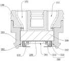
为了解决上述问题,根据本申请的一个方面,本申请的实施例提供了一种雾化组件,如图1所示,该雾化组件包括可拆卸连接的上支架100和下支架200以及被夹持于上支架100和下支架200之间并相互贴合的导液棉块300和网状发热片400;上支架100上设置有用于向导液棉块300通液的导液通道101;下支架200上设置有雾化出口201以及两引脚出口202;网状发热片400连接有两导电引脚410,两导电引脚410远离网状发热片400的一端分别穿过两引脚出口202后弯折形成用于抵接导电电极的两导电部。In order to solve the above problems, according to an aspect of the present application, an embodiment of the present application provides an atomization assembly, as shown in FIG. 1 , the atomization assembly includes a detachably connected
在本发明实施例中,雾化组件通过可拆卸连接的上支架100和下支架200将导液棉块300和网状发热片400进行夹持,下支架200上设置有雾化出口201以及两引脚出口202,网状发热片400连接有两导电引脚410,两导电引脚410远离网状发热片400的一端分别穿过两引脚出口202后弯折形成用于抵接导电电极的两导电部,由此设计的雾化组件结构简单,避免了传统的导油棉和发热丝缠绕以及陶瓷和发热丝烧结的复杂制作工艺,便于制作及自动化装配,有利于降低雾化器的生产制造成本以及便于后期的维护。In the embodiment of the present invention, the atomization assembly clamps the liquid-conducting
需要说明的是,本实施例中雾化组件可用于电子烟的烟弹中以雾化烟油,也可用于医疗器械中以雾化药液等,本发明实施例中将雾化组件用于电子烟的烟弹中以雾化烟油为例进行说明,但并不以此为限。It should be noted that the atomizing assembly in this embodiment can be used in the cartridge of the electronic cigarette to atomize the e-liquid, and can also be used in the medical device to atomize the liquid medicine, etc. In the embodiment of the present invention, the atomizing assembly is used for The cartridge of the electronic cigarette takes the atomized e-liquid as an example to illustrate, but it is not limited to this.
可以理解的是,导液棉块300和网状发热片400通过上支架100和下支架200固定并相互贴合,可拆卸连接的上支架100和下支架200,具有便于雾化组件安装和后期部分零部件更换的优点,具体来说,上支架100与下支架200可通过螺接、卡接、插接或过盈配合等常规的可拆卸方式连接在一起。It can be understood that the liquid-conducting
该雾化组件作为雾化器的一部分,需要与外壳700配合形成雾化器,外壳700内设置有用于存储烟油的储液腔701,导液通道101纵向贯穿上支架100以使烟油能够从储液腔701内通过该导液通道101浸入导液棉块300中,导液通道101的形状不作限定,可以是任意形状的贯通的孔,本实施例中为两个内径渐缩的孔。As a part of the atomizer, the atomizer assembly needs to cooperate with the
网状发热片400用于加热导液棉块300内浸入的烟油,网状发热片400为片状,其上设置的网孔与下支架200上设置的雾化出口201对应,网孔大小可以根据实际需要设定,网孔形状不限定。导液棉块300在上支架100和下支架200的夹持下与网状发热片400完全贴合,利于均匀加热导液棉块300,使其浸润的烟油受热雾化形成烟雾。两导电引脚410可分别连接在网状发热片400长度方向的两端并与网状发热片400为一体式结构,可采用镍、镍铬、镍钛、钛、不锈钢等薄片通过激光镭射、CNC加工、冲压或蚀刻制成。The
在一种实施例中,如图1和图4所示,网状发热片400具有用于和导液棉块300贴合的接触面,网状发热片400包括开设有网孔的发热部401和与发热部401的长度方向两端分别连接的两连接部402,两个带状的导电引脚410分别连接于两连接部402背离接触面的一侧。当网状发热片400在下支架200上安装到位后,导电引脚410穿设于引脚出口202内,导电引脚410远离连接部402的一端伸出引脚出口202并弯折形成导电部412,导电引脚410位于引脚出口202内的部分形成连接连接部402与导电部412的弯折部411。In one embodiment, as shown in FIG. 1 and FIG. 4 , the
进一步地,发热部401上设置有向接触面朝向的一侧延伸的发热柱420。Further, the
通过在发热部401上设置发热柱420,增大了发热面积,将导液棉块300置于网状发热片400上并与接触面贴合后,发热柱420能够插入导液棉块300内部,配合发热部401既能起到均匀加热导液棉块300的作用,使浸入导液棉块300内的烟油快速吸热雾化,同时发热柱420还能够对导液棉块300起到固定作用,使导液棉块300与网状发热片400之间的连接更加稳固可靠。By disposing the
优选地,发热柱420均匀设置于发热部401的长度方向的两侧。Preferably, the
可以理解的是,发热柱420由具有导电性的金属或合金制成,例如,可以由铁、铝、铜、镍、钛、铝合金、镁合金、铜合金、镍铬合金、钛合金、高速钢或不锈钢等制成。It can be understood that the
在一种实施例中,如图1-图3所示,雾化组件还包括隔热件500,隔热件500设置于网状发热片400与下支架200之间,且隔热件500上设置有与雾化出口201对应的中心孔501和与两引脚出口202一一对应的两豁口502。In an embodiment, as shown in FIGS. 1 to 3 , the atomization assembly further includes a
通过在网状发热片400与下支架200之间设置隔热件500,可通过隔热件500将网状发热片400与下支架200隔离开,避免网状发热片400与下支架200之间直接接触,可降低对下支架200材质的要求,进而降低成本。By arranging the
需要说明的是,当未设置隔热件500时,下支架200需采用耐高温的材质,如PEEK、铁氟龙等材料,可通过注塑或机加工工艺制成。It should be noted that, when the
在一种具体的实施例中,上支架100和隔热件500为硅胶材质。In a specific embodiment, the
硅胶主要成分是二氧化硅,化学性质稳定,无毒无味,不燃烧,耐高温,将上支架100和隔热件500采用硅胶制成,可防止烟油与上支架100和隔热件500接触反应导致烟油变质,通过硅胶材质的隔热件500不仅能够起到隔热作用,由于硅胶具有弹性,还能够密封除隔热件500上中心孔501和两豁口502外其余部分与下支架200之间的间隙,防止烟油泄露。The main component of silica gel is silicon dioxide, which is chemically stable, non-toxic, tasteless, non-combustible, and resistant to high temperature. The reaction leads to the deterioration of the e-liquid, and the
在一种具体的实施例中,如图1-图3所示,隔热件500包括主体510和与主体510连接的两扣钩520,中心孔501和两豁口502设置于主体510上,两扣钩520分别穿过两引脚出口202并扣接于下支架200上位于引脚出口202与雾化出口201之间的部分上,导电引脚410伸出引脚出口202的部分向扣钩520弯折并贴合于扣钩520上以形成导电部。In a specific embodiment, as shown in FIG. 1 to FIG. 3 , the
通过如上设计,利用隔热件500上的两扣钩520分别穿过两引脚出口202并扣接于下支架200上位于引脚出口202与雾化出口201之间的部分上,能够实现隔热件500在下支架200上的安装固定,利用网状发热片400上导电引脚410伸出引脚出口202的部分向扣钩520弯折并贴合于扣钩520上,既能够形成用于与导电电极抵接以向网状发热片400供电的导电部,还能够通过导电引脚410实现对网状发热片400的安装固定。Through the above design, the two
具体来说,主体510和两扣钩520可为一体式结构,可采用硅胶经模具注塑形成。Specifically, the
在一种更加具体的实施例中,如图2-图3所示,下支架200具有第一端和与第一端相对的第二端,第一端上设置有用于容置隔热件500、网状发热片400和导液棉块300的容置槽210,雾化出口201和两引脚出口202贯穿容置槽210的槽底和第二端设置,上支架100包括抵接于第一端的限位部110和与限位部110连接并过盈插接于容置槽210内的插入部120,插入部120抵接于导液棉块300以使导液棉块300贴合于网状发热片400。In a more specific embodiment, as shown in FIGS. 2-3 , the
通过将隔热件500、网状发热片400和导液棉块300设置于下支架200上的容置槽210内,利用容置槽210对隔热件500、网状发热片400和导液棉块300进行限位,然后上支架100与容置槽210过盈插接实现对隔热件500、网状发热片400和导液棉块300的压紧固定,结构简单,进一步提高了雾化组件制作的便利性。By arranging the
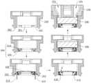
具体来说,如图6所示,在制作雾化组件时,先将隔热件500放置于容置槽210的槽底并使隔热件500上的扣钩520穿过引脚出口202并扣接于下支架200上位于引脚出口202与雾化出口201之间的部分上;再将网状发热片400放置于隔热件500上并将导电引脚410远离网状发热片400的一端伸出引脚出口202后向扣钩520弯折并贴合于扣钩520上以形成导电部;然后将导液棉块300放置于网状发热片400上;最后将上支架100的插入部120过盈插接于容置槽210内并抵接于导液棉块300。Specifically, as shown in FIG. 6 , when making the atomization assembly, first place the
当然,可以理解的是,在其他实施例中,容置槽210可以单独设置在上支架100的底部,也可以在上支架100的底部和下支架200的顶部都设置容置空间,共同形成容置槽210。Of course, it can be understood that, in other embodiments, the
在进一步具体的实施例中,如图2-3所示,容置槽210包括由槽口至槽底依次设置的插接段212和容置段211,隔热件500、网状发热片400和导液棉块300收容于容置段211内,插入部120包括位于插入段内的插入连接部121和位于容置段211内并抵接于导液棉块300的插入抵接部122,下支架200的外侧壁上设置有与插接段212连通的过气孔203以及与过气孔203连通并延伸至第二端的过气槽204,限位部110上设置有出气口102,插入连接部121上设置有将过气孔203与出气口102连通的过气通道103。In a further specific embodiment, as shown in FIGS. 2-3 , the
通过如上设置,当该雾化组件设置于外壳700内后,下支架200外侧壁上的过气槽204与壳体内壁之间形成过烟间隙,过烟间隙配合插入连接部121上的过气通道103和限位部110上的出气口102构成整个雾化器气路的一部分,使得整个雾化器结构更加紧凑。With the above arrangement, when the atomizing assembly is installed in the
在一些具体的实施例中,如图5所示,雾化组件还包括底座600以及设置于底座600上的两导电电极610,底座600套接于下支架200上,底座600上设置有与雾化出口201连通的进气通道601,两导电电极610分别抵接于两导电部,网状发热片400能够通过导电电极610接入电源的正负极实现发热,以将导液棉块300吸附的液体蒸发雾化。In some specific embodiments, as shown in FIG. 5 , the atomizing assembly further includes a
具体来说,底座600采用绝缘材料制成,两导电电极610为贯穿底座600并与底座600紧配合的两电极柱,两电极柱的一端分别与两导电部抵接,两电极柱的另一端位于底座600背离下支架200的一端并用于分别与主机上的电源正负极接触导电。Specifically, the
如图7-图8所示,具有底座600及导电电极610的雾化组件需一同装入外壳700内以形成雾化器,需要说明的是,外壳700内设置有与储液腔701分隔的中心管710,中心管710内形成出气通道711,当雾化组件装入外壳700后,储液腔701内的烟油能够通过上支架100上的导液通道101浸入导液棉块300内(烟油流动方向见图7中的箭头所指示的路径),中心管710位于外壳700内的一端过盈插入上支架100上的出气口102中,中心管710另一端在外壳700上形成以供用户吸食的抽吸口712,当雾化器安装至主机上(雾化器与主机之间可通过磁吸连接)之后,两电极柱位于底座600背离下支架200的一端分别与主机上的电源正负极接触,电源通过两电极柱为网状发热片400通电加热,使进入导液棉块300内的烟油雾化形成烟雾,随着用户在抽吸口712的抽吸,外界空气经底座600上的进气通道601流入,与烟雾混合后依次流经下支架200外侧壁上的过气槽204与壳体内壁之间形成过烟间隙、插入连接部121上的过气通道103、限位部110上的出气口102和中心管710内的出气通道711被用户吸食(气体流动方向见图8中箭头所指示的路径)。As shown in FIGS. 7-8 , the atomizing assembly having the base 600 and the
根据本申请的另一个方面,本申请的实施例还提供了一种雾化组件制作方法,如图6所示,该制作方法包括以下步骤:According to another aspect of the present application, an embodiment of the present application also provides a method for manufacturing an atomizing component, as shown in FIG. 6 , the manufacturing method includes the following steps:
提供具有雾化出口201和两引脚出口202的下支架200;A
将连接有两导电引脚410的网状发热片400放置于下支架200上,并使两导电引脚410远离网状发热片400的一端分别穿过两引脚出口202;The
通过外力将网状发热片400压在下支架200上,将两导电引脚410伸出引脚出口202的部分弯折以形成用于抵接导电电极610的两导电部;The
将导液棉块300放置于网状发热片400上;Place the liquid guiding
将具有导液通道101的上支架100压在导液棉块300上并将上支架100与下支架200之间可拆卸地连接。The
在本发明实施例中,通过该雾化组件制作方法能够简单快速地制备雾化组件,避免了传统的导油棉和发热丝缠绕以及陶瓷和发热丝烧结的复杂制作工艺,便于自动化装配,有利于降低雾化器的生产制造成本,以及便于后期的维护。In the embodiment of the present invention, the atomization assembly can be prepared simply and quickly by the method for manufacturing the atomization assembly, which avoids the traditional complicated manufacturing process of winding oil-conducting cotton and heating wire and sintering ceramic and heating wire, which is convenient for automatic assembly. It is beneficial to reduce the manufacturing cost of the atomizer and facilitate later maintenance.
在一种实施例中,如图6所示,在将连接有两导电引脚410的网状发热片400放置于下支架200之前,将隔热件500放置于下支架200上。In one embodiment, as shown in FIG. 6 , before placing the
通过在网状发热片400与下支架200之间设置隔热件500,可通过隔热件500将网状发热片400与下支架200隔离开,避免网状发热片400与下支架200之间直接接触,可降低对下支架200材质的要求,进而降低成本。By arranging the
需要说明的是,当未设置隔热件500时,下支架200需采用耐高温的材质,如PEEK、铁氟龙等材料,可通过注塑或机加工工艺制成。It should be noted that, when the
在一种具体的实施例中,如图6所示,隔热件500包括主体510和与主体510连接的两扣钩520,主体510上设置有与雾化出口201对应的中心孔501和与两引脚出口202一一对应的两豁口502,两扣钩520分别穿过两引脚出口202并扣接于下支架200上位于引脚出口202与雾化出口201之间的部分上。In a specific embodiment, as shown in FIG. 6 , the
通过如上设计,利用隔热件500上的两扣钩520分别穿过两引脚出口202并扣接于下支架200上位于引脚出口202与雾化出口201之间的部分上,能够实现隔热件500在下支架200上的安装固定,利用网状发热片400上导电引脚410伸出引脚出口202的部分向扣钩520弯折并贴合于扣钩520上,既能够形成用于与导电电极610抵接以向网状发热片400供电的导电部,还能够通过导电引脚410实现对网状发热片400的安装固定。Through the above design, the two
综上,实施本实施例提供的雾化组件及其制作方法,至少具有以下有益技术效果:To sum up, implementing the atomizing assembly and the manufacturing method thereof provided by this embodiment at least has the following beneficial technical effects:
该雾化组件通过可拆卸连接的上支架100和下支架200将导液棉块300和网状发热片400进行夹持,下支架200上设置有雾化出口201以及两引脚出口202,网状发热片400连接有两导电引脚410,两导电引脚410远离网状发热片400的一端分别穿过两引脚出口202后弯折形成用于抵接导电电极610的两导电部,由此设计的雾化组件结构简单,便于制作及自动化装配,有利于降低雾化器的生产制造成本以及便于后期的维护;本申请雾化组件制作方法能够简单快速地制备雾化组件,避免了传统的导油棉和发热丝缠绕以及陶瓷和发热丝烧结的复杂制作工艺,便于自动化装配,有利于降低雾化器的生产制造成本,以及便于后期的维护。The atomization assembly clamps the liquid-conducting
以上实施例的各技术特征可以进行任意的组合,为使描述简洁,未对上述实施例中的各个技术特征所有可能的组合都进行描述,然而,只要这些技术特征的组合不存在矛盾,都应当认为是本说明书记载的范围。The technical features of the above embodiments can be combined arbitrarily. For the sake of brevity, all possible combinations of the technical features in the above embodiments are not described. However, as long as there is no contradiction in the combination of these technical features, all It is considered to be the range described in this specification.
以上实施例仅表达了本发明的几种实施方式,其描述较为具体和详细,但并不能因此而理解为对申请范围的限制。应当指出的是,对于本领域的普通技术人员来说,在不脱离本发明构思的前提下,还可以做出若干变形和改进,这些都属于本发明的保护范围。因此,本发明的保护范围应以所附权利要求为准。The above examples only represent several embodiments of the present invention, and the descriptions thereof are relatively specific and detailed, but should not be construed as a limitation on the scope of the application. It should be pointed out that for those skilled in the art, without departing from the concept of the present invention, several modifications and improvements can be made, which all belong to the protection scope of the present invention. Therefore, the scope of protection of the present invention should be determined by the appended claims.
Claims (10)
Priority Applications (1)
| Application Number | Priority Date | Filing Date | Title |
|---|---|---|---|
| CN202210025354.6ACN114376272B (en) | 2022-01-11 | 2022-01-11 | Atomization assembly and manufacturing method thereof |
Applications Claiming Priority (1)
| Application Number | Priority Date | Filing Date | Title |
|---|---|---|---|
| CN202210025354.6ACN114376272B (en) | 2022-01-11 | 2022-01-11 | Atomization assembly and manufacturing method thereof |
Publications (2)
| Publication Number | Publication Date |
|---|---|
| CN114376272Atrue CN114376272A (en) | 2022-04-22 |
| CN114376272B CN114376272B (en) | 2025-08-19 |
Family
ID=81199718
Family Applications (1)
| Application Number | Title | Priority Date | Filing Date |
|---|---|---|---|
| CN202210025354.6AActiveCN114376272B (en) | 2022-01-11 | 2022-01-11 | Atomization assembly and manufacturing method thereof |
Country Status (1)
| Country | Link |
|---|---|
| CN (1) | CN114376272B (en) |
Cited By (9)
| Publication number | Priority date | Publication date | Assignee | Title |
|---|---|---|---|---|
| CN115024517A (en)* | 2022-07-25 | 2022-09-09 | 美满芯盛(杭州)微电子有限公司 | A liquid atomization module based on a silicon-based atomization core and its assembly method |
| CN115053991A (en)* | 2022-06-02 | 2022-09-16 | 深圳麦克韦尔科技有限公司 | Atomization assembly, atomizer and electronic atomization device |
| CN115211599A (en)* | 2022-08-22 | 2022-10-21 | 东莞市克莱鹏雾化科技有限公司 | Atomizing device based on netted piece that generates heat |
| CN115245210A (en)* | 2022-05-09 | 2022-10-28 | 深圳市赛尔美电子科技有限公司 | Method for assembling atomizer |
| CN115256970A (en)* | 2022-08-31 | 2022-11-01 | 深圳市鑫霖美科技有限公司 | Automatic atomization module manufacturing mechanism and automatic atomization module manufacturing equipment |
| CN115363285A (en)* | 2022-07-25 | 2022-11-22 | 美满芯盛(杭州)微电子有限公司 | A silicon-based atomizing core with uniform heating and measurable temperature and its manufacturing method |
| WO2023124327A1 (en)* | 2021-12-30 | 2023-07-06 | 深圳市艾溹技术研究有限公司 | Atomizer, atomization core, and manufacturing method therefor |
| WO2023220869A1 (en)* | 2022-05-16 | 2023-11-23 | 深圳市华诚达精密工业有限公司 | Electronic atomization assembly convenient to assemble and difficult to leak and manufacturing method therefor |
| WO2024149411A1 (en)* | 2023-01-09 | 2024-07-18 | 现代精密塑胶模具(深圳)有限公司 | Atomizer and electronic atomization device |
Citations (10)
| Publication number | Priority date | Publication date | Assignee | Title |
|---|---|---|---|---|
| CN207444278U (en)* | 2017-09-25 | 2018-06-05 | 深圳易捷威博电子科技有限公司 | A kind of atomizer and electronic cigarette with composite heating system |
| CN209628633U (en)* | 2018-12-24 | 2019-11-15 | 深圳市合元科技有限公司 | Electronic cigarette atomizer and electronic cigarette including the electronic cigarette atomizer |
| WO2020038780A1 (en)* | 2018-08-22 | 2020-02-27 | Philip Morris Products S.A. | Heater assembly with anchoring legs |
| CN111374352A (en)* | 2020-04-08 | 2020-07-07 | 深圳市思源贝尔科技有限公司 | Electronic cigarette heating component and portable small-smoke electronic cigarette atomizer thereof |
| WO2020155477A1 (en)* | 2019-01-31 | 2020-08-06 | 欧俊彪 | Ceramic heating body, atomization core and atomizer using ceramic heating body |
| CN111493360A (en)* | 2019-01-29 | 2020-08-07 | 常州市派腾电子技术服务有限公司 | Cigarette bullet and electron cigarette |
| US20200397043A1 (en)* | 2018-02-13 | 2020-12-24 | Shenzhen Smoore Technology Limited | Electronic cigarette and heating assembly thereof |
| CN113142676A (en)* | 2020-12-31 | 2021-07-23 | 深圳麦克韦尔科技有限公司 | A kind of electronic atomization device, atomizer and atomizing core thereof |
| WO2021189643A1 (en)* | 2020-03-27 | 2021-09-30 | 深圳市华诚达精密工业有限公司 | Mesh-shaped sheet-type porous heating atomization assembly and heating atomizer therewith |
| CN113662256A (en)* | 2021-08-20 | 2021-11-19 | 深圳市艾溹技术研究有限公司 | Atomizer and atomizing device |
- 2022
- 2022-01-11CNCN202210025354.6Apatent/CN114376272B/enactiveActive
Patent Citations (10)
| Publication number | Priority date | Publication date | Assignee | Title |
|---|---|---|---|---|
| CN207444278U (en)* | 2017-09-25 | 2018-06-05 | 深圳易捷威博电子科技有限公司 | A kind of atomizer and electronic cigarette with composite heating system |
| US20200397043A1 (en)* | 2018-02-13 | 2020-12-24 | Shenzhen Smoore Technology Limited | Electronic cigarette and heating assembly thereof |
| WO2020038780A1 (en)* | 2018-08-22 | 2020-02-27 | Philip Morris Products S.A. | Heater assembly with anchoring legs |
| CN209628633U (en)* | 2018-12-24 | 2019-11-15 | 深圳市合元科技有限公司 | Electronic cigarette atomizer and electronic cigarette including the electronic cigarette atomizer |
| CN111493360A (en)* | 2019-01-29 | 2020-08-07 | 常州市派腾电子技术服务有限公司 | Cigarette bullet and electron cigarette |
| WO2020155477A1 (en)* | 2019-01-31 | 2020-08-06 | 欧俊彪 | Ceramic heating body, atomization core and atomizer using ceramic heating body |
| WO2021189643A1 (en)* | 2020-03-27 | 2021-09-30 | 深圳市华诚达精密工业有限公司 | Mesh-shaped sheet-type porous heating atomization assembly and heating atomizer therewith |
| CN111374352A (en)* | 2020-04-08 | 2020-07-07 | 深圳市思源贝尔科技有限公司 | Electronic cigarette heating component and portable small-smoke electronic cigarette atomizer thereof |
| CN113142676A (en)* | 2020-12-31 | 2021-07-23 | 深圳麦克韦尔科技有限公司 | A kind of electronic atomization device, atomizer and atomizing core thereof |
| CN113662256A (en)* | 2021-08-20 | 2021-11-19 | 深圳市艾溹技术研究有限公司 | Atomizer and atomizing device |
Cited By (11)
| Publication number | Priority date | Publication date | Assignee | Title |
|---|---|---|---|---|
| WO2023124327A1 (en)* | 2021-12-30 | 2023-07-06 | 深圳市艾溹技术研究有限公司 | Atomizer, atomization core, and manufacturing method therefor |
| CN115245210A (en)* | 2022-05-09 | 2022-10-28 | 深圳市赛尔美电子科技有限公司 | Method for assembling atomizer |
| CN115245210B (en)* | 2022-05-09 | 2025-08-19 | 深圳市赛尔美电子科技有限公司 | Method for assembling atomizer |
| WO2023220869A1 (en)* | 2022-05-16 | 2023-11-23 | 深圳市华诚达精密工业有限公司 | Electronic atomization assembly convenient to assemble and difficult to leak and manufacturing method therefor |
| CN115053991A (en)* | 2022-06-02 | 2022-09-16 | 深圳麦克韦尔科技有限公司 | Atomization assembly, atomizer and electronic atomization device |
| CN115024517A (en)* | 2022-07-25 | 2022-09-09 | 美满芯盛(杭州)微电子有限公司 | A liquid atomization module based on a silicon-based atomization core and its assembly method |
| CN115363285A (en)* | 2022-07-25 | 2022-11-22 | 美满芯盛(杭州)微电子有限公司 | A silicon-based atomizing core with uniform heating and measurable temperature and its manufacturing method |
| CN115211599A (en)* | 2022-08-22 | 2022-10-21 | 东莞市克莱鹏雾化科技有限公司 | Atomizing device based on netted piece that generates heat |
| WO2024041092A1 (en)* | 2022-08-22 | 2024-02-29 | 东莞市克莱鹏雾化科技有限公司 | Mesh heating piece-based atomization device |
| CN115256970A (en)* | 2022-08-31 | 2022-11-01 | 深圳市鑫霖美科技有限公司 | Automatic atomization module manufacturing mechanism and automatic atomization module manufacturing equipment |
| WO2024149411A1 (en)* | 2023-01-09 | 2024-07-18 | 现代精密塑胶模具(深圳)有限公司 | Atomizer and electronic atomization device |
Also Published As
| Publication number | Publication date |
|---|---|
| CN114376272B (en) | 2025-08-19 |
Similar Documents
| Publication | Publication Date | Title |
|---|---|---|
| CN114376272A (en) | Atomizing component and method of making the same | |
| CN110652039B (en) | Electronic aerosol supply system and equipment therefor | |
| WO2017121296A1 (en) | Atomization head, atomizer and electronic cigarette comprising same | |
| CN210869884U (en) | Atomizers and Electronic Cigarettes | |
| CN106983177B (en) | Electronic cigarette and its atomizing device | |
| CN105768225A (en) | Smoke bomb and electronic cigarette using it | |
| WO2017156696A1 (en) | Electronic cigarette atomizer and forming device for heat generating body thereof, and method for manufacturing heat generating body | |
| CN209106324U (en) | Print heater atomizer and electronic cigarette | |
| CN209931485U (en) | Cigarette heaters and electrically heated smoking devices | |
| CN207428416U (en) | Atomising head and its electronic cigarette | |
| CN113455736B (en) | Atomizer and electronic atomization device | |
| CN216315620U (en) | Heating assembly, atomizer and electronic atomization device | |
| CN216255475U (en) | Electronic atomization device | |
| CN113876045A (en) | Modular heating core assembly, atomizing device and atomizing equipment | |
| CN108618204B (en) | Atomizer and electronic cigarette | |
| CN210580985U (en) | Tobacco juice atomizing device and electron cigarette | |
| WO2025161793A1 (en) | Atomizer provided with flat plate-shaped liquid guide layer | |
| CN212877615U (en) | A kind of atomizer and electric heating atomization device | |
| WO2023051545A1 (en) | End cover structure and electronic atomization apparatus | |
| CN210329335U (en) | Atomizer and its electronic cigarette | |
| CN114886163A (en) | Heating element, atomizer and aerosol generating device | |
| CN216255474U (en) | Electronic atomization device | |
| CN110710713B (en) | Electronic atomization device and smoke tube assembly thereof | |
| CN111838771A (en) | Electronic cigarette and atomization device thereof | |
| CN216983626U (en) | Modular heating core assembly, atomizing device and atomizing equipment |
Legal Events
| Date | Code | Title | Description |
|---|---|---|---|
| PB01 | Publication | ||
| PB01 | Publication | ||
| SE01 | Entry into force of request for substantive examination | ||
| SE01 | Entry into force of request for substantive examination | ||
| GR01 | Patent grant | ||
| GR01 | Patent grant |