CN114375182A - System and method for kinematic optimization using shared robot degrees of freedom - Google Patents
System and method for kinematic optimization using shared robot degrees of freedomDownload PDFInfo
- Publication number
- CN114375182A CN114375182ACN202080064052.9ACN202080064052ACN114375182ACN 114375182 ACN114375182 ACN 114375182ACN 202080064052 ACN202080064052 ACN 202080064052ACN 114375182 ACN114375182 ACN 114375182A
- Authority
- CN
- China
- Prior art keywords
- robotic
- arm support
- adjustable arm
- patient
- arm
- Prior art date
- Legal status (The legal status is an assumption and is not a legal conclusion. Google has not performed a legal analysis and makes no representation as to the accuracy of the status listed.)
- Pending
Links
Images


Classifications
- A—HUMAN NECESSITIES
- A61—MEDICAL OR VETERINARY SCIENCE; HYGIENE
- A61B—DIAGNOSIS; SURGERY; IDENTIFICATION
- A61B34/00—Computer-aided surgery; Manipulators or robots specially adapted for use in surgery
- A61B34/30—Surgical robots
- A—HUMAN NECESSITIES
- A61—MEDICAL OR VETERINARY SCIENCE; HYGIENE
- A61B—DIAGNOSIS; SURGERY; IDENTIFICATION
- A61B34/00—Computer-aided surgery; Manipulators or robots specially adapted for use in surgery
- A61B34/30—Surgical robots
- A61B34/35—Surgical robots for telesurgery
- A—HUMAN NECESSITIES
- A61—MEDICAL OR VETERINARY SCIENCE; HYGIENE
- A61B—DIAGNOSIS; SURGERY; IDENTIFICATION
- A61B34/00—Computer-aided surgery; Manipulators or robots specially adapted for use in surgery
- A61B34/30—Surgical robots
- A61B34/37—Leader-follower robots
- A—HUMAN NECESSITIES
- A61—MEDICAL OR VETERINARY SCIENCE; HYGIENE
- A61B—DIAGNOSIS; SURGERY; IDENTIFICATION
- A61B34/00—Computer-aided surgery; Manipulators or robots specially adapted for use in surgery
- A61B34/70—Manipulators specially adapted for use in surgery
- A61B34/74—Manipulators with manual electric input means
- B—PERFORMING OPERATIONS; TRANSPORTING
- B25—HAND TOOLS; PORTABLE POWER-DRIVEN TOOLS; MANIPULATORS
- B25J—MANIPULATORS; CHAMBERS PROVIDED WITH MANIPULATION DEVICES
- B25J15/00—Gripping heads and other end effectors
- B25J15/0019—End effectors other than grippers
- B—PERFORMING OPERATIONS; TRANSPORTING
- B25—HAND TOOLS; PORTABLE POWER-DRIVEN TOOLS; MANIPULATORS
- B25J—MANIPULATORS; CHAMBERS PROVIDED WITH MANIPULATION DEVICES
- B25J15/00—Gripping heads and other end effectors
- B25J15/0052—Gripping heads and other end effectors multiple gripper units or multiple end effectors
- B—PERFORMING OPERATIONS; TRANSPORTING
- B25—HAND TOOLS; PORTABLE POWER-DRIVEN TOOLS; MANIPULATORS
- B25J—MANIPULATORS; CHAMBERS PROVIDED WITH MANIPULATION DEVICES
- B25J5/00—Manipulators mounted on wheels or on carriages
- B25J5/007—Manipulators mounted on wheels or on carriages mounted on wheels
- B—PERFORMING OPERATIONS; TRANSPORTING
- B25—HAND TOOLS; PORTABLE POWER-DRIVEN TOOLS; MANIPULATORS
- B25J—MANIPULATORS; CHAMBERS PROVIDED WITH MANIPULATION DEVICES
- B25J9/00—Programme-controlled manipulators
- B25J9/0084—Programme-controlled manipulators comprising a plurality of manipulators
- B25J9/0087—Dual arms
- B—PERFORMING OPERATIONS; TRANSPORTING
- B25—HAND TOOLS; PORTABLE POWER-DRIVEN TOOLS; MANIPULATORS
- B25J—MANIPULATORS; CHAMBERS PROVIDED WITH MANIPULATION DEVICES
- B25J9/00—Programme-controlled manipulators
- B25J9/06—Programme-controlled manipulators characterised by multi-articulated arms
- B—PERFORMING OPERATIONS; TRANSPORTING
- B25—HAND TOOLS; PORTABLE POWER-DRIVEN TOOLS; MANIPULATORS
- B25J—MANIPULATORS; CHAMBERS PROVIDED WITH MANIPULATION DEVICES
- B25J9/00—Programme-controlled manipulators
- B25J9/16—Programme controls
- B—PERFORMING OPERATIONS; TRANSPORTING
- B25—HAND TOOLS; PORTABLE POWER-DRIVEN TOOLS; MANIPULATORS
- B25J—MANIPULATORS; CHAMBERS PROVIDED WITH MANIPULATION DEVICES
- B25J9/00—Programme-controlled manipulators
- B25J9/16—Programme controls
- B25J9/1628—Programme controls characterised by the control loop
- B25J9/1643—Programme controls characterised by the control loop redundant control
- B—PERFORMING OPERATIONS; TRANSPORTING
- B25—HAND TOOLS; PORTABLE POWER-DRIVEN TOOLS; MANIPULATORS
- B25J—MANIPULATORS; CHAMBERS PROVIDED WITH MANIPULATION DEVICES
- B25J9/00—Programme-controlled manipulators
- B25J9/16—Programme controls
- B25J9/1656—Programme controls characterised by programming, planning systems for manipulators
- B25J9/1664—Programme controls characterised by programming, planning systems for manipulators characterised by motion, path, trajectory planning
- B25J9/1666—Avoiding collision or forbidden zones
- B—PERFORMING OPERATIONS; TRANSPORTING
- B25—HAND TOOLS; PORTABLE POWER-DRIVEN TOOLS; MANIPULATORS
- B25J—MANIPULATORS; CHAMBERS PROVIDED WITH MANIPULATION DEVICES
- B25J9/00—Programme-controlled manipulators
- B25J9/16—Programme controls
- B25J9/1679—Programme controls characterised by the tasks executed
- B25J9/1689—Teleoperation
- A—HUMAN NECESSITIES
- A61—MEDICAL OR VETERINARY SCIENCE; HYGIENE
- A61B—DIAGNOSIS; SURGERY; IDENTIFICATION
- A61B34/00—Computer-aided surgery; Manipulators or robots specially adapted for use in surgery
- A61B34/20—Surgical navigation systems; Devices for tracking or guiding surgical instruments, e.g. for frameless stereotaxis
- A61B2034/2046—Tracking techniques
- A61B2034/2059—Mechanical position encoders
- A—HUMAN NECESSITIES
- A61—MEDICAL OR VETERINARY SCIENCE; HYGIENE
- A61B—DIAGNOSIS; SURGERY; IDENTIFICATION
- A61B34/00—Computer-aided surgery; Manipulators or robots specially adapted for use in surgery
- A61B34/30—Surgical robots
- A61B2034/301—Surgical robots for introducing or steering flexible instruments inserted into the body, e.g. catheters or endoscopes
- A—HUMAN NECESSITIES
- A61—MEDICAL OR VETERINARY SCIENCE; HYGIENE
- A61B—DIAGNOSIS; SURGERY; IDENTIFICATION
- A61B34/00—Computer-aided surgery; Manipulators or robots specially adapted for use in surgery
- A61B34/30—Surgical robots
- A61B2034/302—Surgical robots specifically adapted for manipulations within body cavities, e.g. within abdominal or thoracic cavities
- A—HUMAN NECESSITIES
- A61—MEDICAL OR VETERINARY SCIENCE; HYGIENE
- A61B—DIAGNOSIS; SURGERY; IDENTIFICATION
- A61B34/00—Computer-aided surgery; Manipulators or robots specially adapted for use in surgery
- A61B34/30—Surgical robots
- A61B2034/303—Surgical robots specifically adapted for manipulations within body lumens, e.g. within lumen of gut, spine, or blood vessels
- A—HUMAN NECESSITIES
- A61—MEDICAL OR VETERINARY SCIENCE; HYGIENE
- A61B—DIAGNOSIS; SURGERY; IDENTIFICATION
- A61B90/00—Instruments, implements or accessories specially adapted for surgery or diagnosis and not covered by any of the groups A61B1/00 - A61B50/00, e.g. for luxation treatment or for protecting wound edges
- A61B90/06—Measuring instruments not otherwise provided for
- A61B2090/064—Measuring instruments not otherwise provided for for measuring force, pressure or mechanical tension
- A61B2090/066—Measuring instruments not otherwise provided for for measuring force, pressure or mechanical tension for measuring torque
- G—PHYSICS
- G05—CONTROLLING; REGULATING
- G05B—CONTROL OR REGULATING SYSTEMS IN GENERAL; FUNCTIONAL ELEMENTS OF SUCH SYSTEMS; MONITORING OR TESTING ARRANGEMENTS FOR SUCH SYSTEMS OR ELEMENTS
- G05B2219/00—Program-control systems
- G05B2219/30—Nc systems
- G05B2219/40—Robotics, robotics mapping to robotics vision
- G05B2219/40201—Detect contact, collision with human
- G—PHYSICS
- G05—CONTROLLING; REGULATING
- G05B—CONTROL OR REGULATING SYSTEMS IN GENERAL; FUNCTIONAL ELEMENTS OF SUCH SYSTEMS; MONITORING OR TESTING ARRANGEMENTS FOR SUCH SYSTEMS OR ELEMENTS
- G05B2219/00—Program-control systems
- G05B2219/30—Nc systems
- G05B2219/40—Robotics, robotics mapping to robotics vision
- G05B2219/40202—Human robot coexistence
Landscapes
- Engineering & Computer Science (AREA)
- Robotics (AREA)
- Health & Medical Sciences (AREA)
- Mechanical Engineering (AREA)
- Life Sciences & Earth Sciences (AREA)
- Surgery (AREA)
- Heart & Thoracic Surgery (AREA)
- Biomedical Technology (AREA)
- Nuclear Medicine, Radiotherapy & Molecular Imaging (AREA)
- Medical Informatics (AREA)
- Molecular Biology (AREA)
- Animal Behavior & Ethology (AREA)
- General Health & Medical Sciences (AREA)
- Public Health (AREA)
- Veterinary Medicine (AREA)
- Manipulator (AREA)
Abstract
Translated fromChinese
Description
Translated fromChinese相关申请的交叉引用CROSS-REFERENCE TO RELATED APPLICATIONS
本申请要求2019年9月10日提交的美国临时申请62/898,472的权益,该申请据此全文以引用方式并入。This application claims the benefit of US
技术领域technical field
本文公开的系统和方法涉及手术机器人,并且更具体地涉及具有共享的机器人自由度的机器人系统。The systems and methods disclosed herein relate to surgical robots, and more particularly to robotic systems with shared robotic degrees of freedom.
背景技术Background technique
医学规程诸如腹腔镜手术可涉及进入患者的内部区域并使患者的内部区域可视化。在腹腔镜规程中,医疗工具可通过腹腔镜插管插入到内部区域中。Medical procedures such as laparoscopic surgery may involve accessing and visualizing an internal area of a patient. In a laparoscopic procedure, a medical tool may be inserted into the interior region through a laparoscopic cannula.
在某些规程中,机器人使能医疗系统可用于控制一个或多个医疗工具的插入和/或操纵。机器人使能医疗系统可以是控制医疗工具的多个机器人臂。在定位医疗工具时,机器人臂的部分可以朝向另一机器人臂或环境中的其它对象移动,这可能导致碰撞。In certain procedures, a robotic-enabled medical system may be used to control the insertion and/or manipulation of one or more medical tools. The robotic-enabled medical system may be multiple robotic arms that control medical tools. When positioning the medical tool, parts of the robotic arm may move towards another robotic arm or other objects in the environment, which may lead to collisions.
发明内容SUMMARY OF THE INVENTION
本公开的系统、方法和装置各自具有若干创新方面,这些创新方面中没有一个独自负责本文所公开的期望属性。The systems, methods, and apparatuses of the present disclosure each have several innovative aspects, none of which are solely responsible for the desirable attributes disclosed herein.
在一个方面,提供了机器人医疗系统,包括:基座;可调式臂支撑件,该可调式臂支撑件耦合到基座;至少一个机器人臂,该至少一个机器人臂耦合到可调式臂支撑件,至少一个机器人臂被配置成被耦合到医疗工具,该医疗工具被配置成通过患者的切口或自然孔口递送;和处理器,该处理器被配置成调整可调式臂支撑件和至少一个机器人臂的位置,同时保持工具的远程移动中心。In one aspect, a robotic medical system is provided, comprising: a base; an adjustable arm support coupled to the base; at least one robotic arm coupled to the adjustable arm support, at least one robotic arm configured to be coupled to a medical tool configured to be delivered through a patient's incision or natural orifice; and a processor configured to adjust the adjustable arm support and the at least one robotic arm location while maintaining the remote mobile center of the tool.
在另一方面,提供了机器人医疗系统,包括:基座;可调式臂支撑件,该可调式臂支撑件耦合到基座;至少一对机器人臂,该至少一对机器人臂耦合到可调式臂支撑件,该对机器人臂各自耦合到工具,该工具被配置成通过患者的切口或自然孔口递送;和处理器,该处理器被配置成调整可调式臂支撑件和一对机器人臂的位置,同时保持工具中的每个工具的远程移动中心。In another aspect, a robotic medical system is provided, comprising: a base; an adjustable arm support coupled to the base; at least one pair of robotic arms coupled to the adjustable arms a support, the pair of robotic arms are each coupled to a tool configured to be delivered through an incision or natural orifice of a patient; and a processor configured to adjust the position of the adjustable arm support and the pair of robotic arms , while maintaining a remote mobility center for each tool in the tool.
在又另一方面,提供了一种医学方法,包括:提供医疗平台,该医疗平台包括耦合到一对机器人臂的可调式臂支撑件,其中机器人臂中的每个机器人臂耦合到医疗工具;以及调整可调式臂支撑件和机器人臂中的每个机器人臂的位置,同时保持工具中的每个工具的远程移动中心。In yet another aspect, a medical method is provided, comprising: providing a medical platform including an adjustable arm support coupled to a pair of robotic arms, wherein each of the robotic arms is coupled to a medical tool; and adjusting the position of the adjustable arm support and each of the robotic arms while maintaining the remote center of motion of each of the tools.
在又另一方面,提供了一种机器人医疗系统,包括:第一组一个或多个连接件,该第一组一个或多个连接件可拆卸地耦合到医疗工具并且被配置成执行第一任务;和第二组一个或多个连接件,该第二组一个或多个连接件被配置成执行不同于第一任务的第二任务,其中第一组一个或多个连接件具有至少一个自由度(DoF),并且第二组一个或多个连接件具有至少一个DoF,并且其中第一组一个或多个连接件和第二组一个或多个连接件中的每一者的至少一个DoF被共享以提供零空间运动。In yet another aspect, a robotic medical system is provided, comprising: a first set of one or more connectors removably coupled to a medical tool and configured to perform a first a task; and a second set of one or more connectors configured to perform a second task different from the first task, wherein the first set of one or more connectors has at least one degrees of freedom (DoF), and the second set of one or more links has at least one DoF, and wherein at least one of each of the first set of one or more links and the second set of one or more links DoF is shared to provide zero space motion.
在另一方面,提供了一种机器人医疗系统,该机器人医疗系统包括一组一个或多个连接件;和患者平台,该患者平台被配置成支撑患者体重的至少一部分,其中一组一个或多个连接件具有至少一个DoF,并且患者平台具有至少一个DoF,并且其中一组一个或多个连接件和患者平台中的每一者的至少一个DoF被共享以提供零空间运动。In another aspect, a robotic medical system is provided, the robotic medical system comprising a set of one or more connectors; and a patient platform configured to support at least a portion of a patient's body weight, wherein the set of one or more Each of the links has at least one DoF and the patient platform has at least one DoF, and the at least one DoF of each of the set of one or more links and the patient platform is shared to provide zero space motion.
在又另一方面,提供了一种方法,包括:移动第一组一个或多个连接件以执行第一任务,其中第一组一个或多个连接件具有至少一个DoF;移动第二组一个或多个连接件以执行不同于第一任务的第二任务,其中第二组一个或多个连接件具有至少一个DoF,其中第一组一个或多个连接件和第二组一个或多个连接件中的每一者的至少一个DoF被共享;以及使用共享的至少一个DoF在零空间中移动第一组一个或多个连接件和第二组一个或多个连接件中的至少一者。In yet another aspect, a method is provided comprising: moving a first set of one or more connectors to perform a first task, wherein the first set of one or more connectors has at least one DoF; moving a second set of one or more connectors to perform a second task different from the first task, wherein the second set of one or more connectors has at least one DoF, wherein the first set of one or more connectors and the second set of one or more at least one DoF of each of the connectors is shared; and moving at least one of the first set of one or more connectors and the second set of one or more connectors in null space using the shared at least one DoF.
在又另一方面,提供了一种方法,包括:移动一组一个或多个连接件,其中第一组一个或多个连接件具有至少一个DoF;移动被配置成支撑患者体重的至少一部分的患者平台,其中患者平台具有至少一个DoF,其中一组一个或多个连接件和患者平台中的每一者的至少一个DoF被共享;以及使用共享的至少一个DoF在零空间中移动一组一个或多个连接件和患者平台中的至少一者。In yet another aspect, a method is provided comprising: moving a set of one or more links, wherein the first set of one or more links has at least one DoF; moving a set of one or more links configured to support at least a portion of a patient's body weight A patient platform, wherein the patient platform has at least one DoF, wherein the at least one DoF of each of the set of one or more connectors and the patient platform is shared; and moving the set of one or more in null space using the shared at least one DoF At least one of a plurality of connectors and a patient platform.
附图说明Description of drawings
下文将结合附图描述所公开的方面,该附图被提供以说明而非限制所公开的方面,其中类似的标号表示类似的元件。The disclosed aspects will be described below in conjunction with the accompanying drawings, which are provided to illustrate and not to limit the disclosed aspects, wherein like reference numerals refer to like elements.
图1示出了被布置用于诊断性和/或治疗性支气管镜检查的基于推车的机器人系统的实施方案。Figure 1 shows an embodiment of a cart-based robotic system deployed for diagnostic and/or therapeutic bronchoscopy.
图2描绘了图1的机器人系统的另外方面。FIG. 2 depicts additional aspects of the robotic system of FIG. 1 .
图3示出了被布置用于输尿管镜检查的图1的机器人系统的实施方案。Figure 3 shows an embodiment of the robotic system of Figure 1 deployed for ureteroscopy.
图4示出了被布置用于血管规程的图1的机器人系统的实施方案。Figure 4 shows an embodiment of the robotic system of Figure 1 deployed for vascular procedures.
图5示出了被布置用于支气管镜检查规程的基于台的机器人系统的实施方案。Figure 5 shows an embodiment of a table-based robotic system deployed for a bronchoscopy procedure.
图6提供了图5的机器人系统的替代视图。FIG. 6 provides an alternate view of the robotic system of FIG. 5 .
图7示出了被配置成收起机器人臂的示例性系统。7 illustrates an example system configured to stow a robotic arm.
图8示出了被配置用于输尿管镜检查规程的基于台的机器人系统的实施方案。8 shows an embodiment of a table-based robotic system configured for a ureteroscopy procedure.
图9示出了被配置用于腹腔镜规程的基于台的机器人系统的实施方案。9 shows an embodiment of a table-based robotic system configured for laparoscopic procedures.
图10示出了图5至图9的具有俯仰和倾斜调节的基于台的机器人系统的实施方案。FIG. 10 shows an embodiment of the table-based robotic system of FIGS. 5-9 with pitch and tilt adjustment.
图11提供了图5至图10的台和基于台的机器人系统的柱之间的接口的详细图示。11 provides a detailed illustration of the interface between the stage of FIGS. 5-10 and the column of the stage-based robotic system.
图12示出了基于台的机器人系统的另选实施方案。Figure 12 shows an alternative embodiment of a table-based robotic system.
图13示出了图12的基于台的机器人系统的端视图。FIG. 13 shows an end view of the table-based robotic system of FIG. 12 .
图14示出了其上附接有机器人臂的基于台的机器人系统的端视图。14 shows an end view of a table-based robotic system with a robotic arm attached thereto.
图15示出了示例性器械驱动器。Figure 15 shows an exemplary instrument driver.
图16示出了具有成对器械驱动器的示例性医疗器械。Figure 16 shows an exemplary medical device with paired device drivers.
图17示出了器械驱动器和器械的另选设计,其中驱动单元的轴线平行于器械的细长轴的轴线。Figure 17 shows an alternative design of the instrument driver and instrument in which the axis of the drive unit is parallel to the axis of the elongated shaft of the instrument.
图18示出了具有基于器械的插入架构的器械。Figure 18 shows an instrument with an instrument-based insertion architecture.
图19示出了示例性控制器。Figure 19 shows an example controller.
图20描绘了根据示例性实施方案的框图,该框图示出了估计图1至图10的机器人系统的一个或多个元件的位置(诸如图16至图18的器械的位置)的定位系统。20 depicts a block diagram illustrating a positioning system that estimates the position of one or more elements of the robotic system of FIGS. 1-10, such as the position of the instrument of FIGS. 16-18, according to an exemplary embodiment .
图21示出了根据本公开的各方面的示例性机器人臂。21 illustrates an exemplary robotic arm in accordance with aspects of the present disclosure.
图22示出了根据本公开的各方面的包括可调式臂支撑件的机器人系统的示例。22 shows an example of a robotic system including an adjustable arm support in accordance with aspects of the present disclosure.
图23示意性地示出了如何在机器人臂、可调式臂支撑件和装配接头之间共享一个或多个自由度(DoF)。Figure 23 schematically illustrates how one or more degrees of freedom (DoF) are shared between the robotic arm, the adjustable arm support and the assembly joint.
图24A和24B示出了根据本公开的各方面的两组连接件的移动,同时保持高级装置操纵器(ADM)和远程移动中心(RCM)的位置。24A and 24B illustrate the movement of two sets of connectors while maintaining the positions of the Advanced Device Manipulator (ADM) and Remote Mobility Center (RCM) in accordance with aspects of the present disclosure.
图25是示出根据本公开的各方面的能够由机器人系统或其部件操作的示例方法的流程图,用于使用共享的机器人DoF在连接件构件之间进行零空间移动。25 is a flowchart illustrating an example method operable by a robotic system or components thereof for zero-space movement between connector members using a shared robotic DoF in accordance with aspects of the present disclosure.
图26是示出根据本公开的各方面的能够由机器人系统或其部件操作的另一示例方法的流程图,用于使用共享的机器人DoF在连接件构件之间进行零空间移动。26 is a flowchart illustrating another example method operable by a robotic system or components thereof for zero-space movement between connector members using a shared robotic DoF, in accordance with aspects of the present disclosure.
图27是示出根据本公开的各方面的能够由机器人系统或其部件操作又一示例方法的流程图,用于使用共享机器人DoF在连接件构件之间进行零空间移动。27 is a flowchart illustrating yet another example method operable by a robotic system or components thereof for zero-space movement between connector members using a shared robotic DoF, in accordance with aspects of the present disclosure.
具体实施方式Detailed ways
1.概述。1. Overview .
本公开的各方面可集成到机器人使能的医疗系统中,该机器人使能的医疗系统能够执行多种医疗规程,包括微创规程诸如腹腔镜检查,以及非侵入规程诸如内窥镜检查两者。在内窥镜检查规程中,系统可能能够执行支气管镜检查、输尿管镜检查、胃镜检查等。Aspects of the present disclosure may be integrated into a robotic-enabled medical system capable of performing a variety of medical procedures, including both minimally invasive procedures such as laparoscopy, and non-invasive procedures such as endoscopy . In an endoscopic procedure, the system may be able to perform bronchoscopy, ureteroscopy, gastroscopy, etc.
除了执行广泛的规程之外,系统可以提供附加的益处,诸如增强的成像和指导以帮助医师。另外,该系统可以为医师提供从人体工程学方位执行规程的能力,而不需要笨拙的臂运动和方位。另外,该系统可以为医师提供以改进的易用性执行规程的能力,使得系统的器械中的一个或多个器械可由单个用户控制。In addition to performing a wide range of procedures, the system can provide additional benefits such as enhanced imaging and guidance to assist physicians. Additionally, the system may provide the physician with the ability to perform procedures from an ergonomic orientation without the need for awkward arm movements and orientations. Additionally, the system may provide the physician with the ability to perform the procedure with improved ease of use, such that one or more of the instruments of the system can be controlled by a single user.
出于说明的目的,下文将结合附图描述各种实施方案。应当理解,所公开的概念的许多其他具体实施是可能的,并且利用所公开的具体实施可实现各种优点。标题包括在本文中以供参考并且有助于定位各个节段。这些标题并非旨在限制相对于其所述的概念的范围。此类概念可在整个说明书中具有适用性。For purposes of illustration, various embodiments are described below in conjunction with the accompanying drawings. It should be understood that many other implementations of the disclosed concepts are possible and that various advantages may be realized using the disclosed implementations. Headings are included herein for reference and to assist in locating the various sections. These headings are not intended to limit the scope of the concepts described with respect to them. Such concepts may have applicability throughout the specification.
A.机器人系统–推车。A. Robotic System – Cart .
机器人使能的医疗系统可以按多种方式配置,这取决于特定规程。图1示出了被布置用于诊断性和/或治疗性支气管镜检查的基于推车的机器人使能的系统10的实施方案。在支气管镜检查期间,系统10可包括推车11,该推车具有一个或多个机器人臂12,以将医疗器械诸如可操纵内窥镜13(其可以是用于支气管镜检查的规程特定的支气管镜)递送至自然孔口进入点(即,在本示例中定位在台上的患者的口),以递送诊断和/或治疗工具。如图所示,推车11可被定位在患者的上躯干附近,以便提供到进入点的通路。类似地,可以致动机器人臂12以相对于进入点定位支气管镜。当用胃镜(用于胃肠道(GI)规程的专用内窥镜)执行GI规程时,也可利用图1中的布置。图2更详细地描绘了推车的示例性实施方案。Robot-enabled medical systems can be configured in a number of ways, depending on the specific protocol. Figure 1 shows an embodiment of a cart-based robot-enabled system 10 deployed for diagnostic and/or therapeutic bronchoscopy. During a bronchoscopy, the system 10 may include a cart 11 having one or more robotic arms 12 to move medical instruments such as a steerable endoscope 13 (which may be procedure specific for bronchoscopy) bronchoscope) to a natural orifice entry point (ie, the patient's mouth positioned on a table in this example) to deliver diagnostic and/or therapeutic tools. As shown, the cart 11 may be positioned adjacent the patient's upper torso to provide access to the point of entry. Similarly, the robotic arm 12 can be actuated to position the bronchoscope relative to the entry point. The arrangement in Figure 1 can also be utilized when performing GI procedures with a gastroscope, a dedicated endoscope for gastrointestinal (GI) procedures. Figure 2 depicts an exemplary embodiment of the cart in more detail.
继续参考图1,一旦推车11被正确定位,机器人臂12就可以机器人地、手动地或以其组合将可操纵内窥镜13插入到患者。如图所示,可操纵内窥镜13可包括至少两个伸缩部分,诸如内引导件部分和外护套部分,每个部分耦合到来自一组器械驱动器28的单独的器械驱动器,每个器械驱动器耦合到单独的机器人臂的远侧端部。有利于将引导件部分与护套部分同轴对准的器械驱动器28的这种线性布置产生“虚拟轨道”29,该“虚拟轨道”可以通过将一个或多个机器人臂12操纵到不同角度和/或方位而在空间中被重新定位。本文所述的虚拟轨道在附图中使用虚线描绘,并且因此虚线未描绘系统的任何物理结构。器械驱动器28沿着虚拟轨道29的平移使内引导件部分相对于外护套部分伸缩,或者使内窥镜13从患者推进或回缩。虚拟轨道29的角度可以基于临床应用或医师偏好来调节、平移和枢转。例如,在支气管镜检查中,如图所示的虚拟轨道29的角度和方位代表了在向医师提供到内窥镜13的通路同时使由内窥镜13弯曲到患者的口中引起的摩擦最小化之间的折衷。With continued reference to FIG. 1 , once the cart 11 is properly positioned, the robotic arm 12 can insert the steerable endoscope 13 into the patient robotically, manually, or a combination thereof. As shown, the steerable endoscope 13 may include at least two telescoping sections, such as an inner guide section and an outer sheath section, each coupled to a separate instrument driver from a set of instrument drivers 28, each instrument A drive is coupled to the distal end of the separate robotic arm. This linear arrangement of instrument driver 28, which facilitates coaxial alignment of the guide portion with the sheath portion, creates a "virtual track" 29 that can be manipulated by manipulating one or more robotic arms 12 to different angles and and/or orientation to be repositioned in space. The virtual tracks described herein are depicted in the figures using dashed lines, and thus the dashed lines do not depict any physical structure of the system. Translation of the instrument driver 28 along the virtual track 29 telescoping the inner guide portion relative to the outer sheath portion, or advancing or retracting the endoscope 13 from the patient. The angle of the virtual track 29 can be adjusted, translated and pivoted based on clinical application or physician preference. For example, in bronchoscopy, the angle and orientation of the virtual track 29 as shown is representative of minimizing friction caused by the bending of the endoscope 13 into the patient's mouth while providing the physician access to the endoscope 13 compromise between.
在插入之后,内窥镜13可以使用来自机器人系统的精确命令向下导向患者的气管和肺,直到到达目标目的地或手术部位。为了增强通过患者的肺网络的导航和/或到达期望的目标,内窥镜13可被操纵以从外部护套部分伸缩地延伸内引导件部分,以获得增强的关节运动和更大的弯曲半径。使用单独的器械驱动器28还允许引导件部分和护套部分彼此独立地被驱动。After insertion, the endoscope 13 can be guided down the patient's trachea and lungs using precise commands from the robotic system until the target destination or surgical site is reached. To enhance navigation through the patient's lung network and/or reach a desired target, the endoscope 13 can be manipulated to telescopically extend the inner guide portion from the outer sheath portion for enhanced articulation and a larger bending radius . Using a separate instrument driver 28 also allows the guide portion and sheath portion to be driven independently of each other.
例如,内窥镜13可被导向以将活检针递送到目标,诸如患者肺内的病变或结节。针可沿工作通道向下部署,该工作通道延伸内窥镜的长度以获得待由病理学家分析的组织样本。根据病理结果,可沿内窥镜的工作通道向下部署附加工具以用于附加活检。在识别出结节是恶性的之后,内窥镜13可以通过内窥镜递送工具以切除潜在的癌组织。在一些情况下,诊断和治疗处理可在单独的规程中递送。在这些情况下,内窥镜13也可用于递送基准以“标记”目标结节的位置。在其他情况下,诊断和治疗处理可在相同的规程期间递送。For example, endoscope 13 may be directed to deliver a biopsy needle to a target, such as a lesion or nodule within a patient's lung. The needle can be deployed down a working channel that extends the length of the endoscope to obtain tissue samples to be analyzed by a pathologist. Depending on the pathology results, additional tools may be deployed down the working channel of the endoscope for additional biopsies. After identifying that the nodule is malignant, the endoscope 13 can deliver a tool through the endoscope to resect the underlying cancerous tissue. In some cases, diagnostic and therapeutic treatments may be delivered in separate procedures. In these cases, the endoscope 13 may also be used to deliver fiducials to "mark" the location of the target nodule. In other cases, diagnostic and therapeutic treatments can be delivered during the same procedure.
系统10还可包括可运动塔30,该可运动塔可经由支撑缆线连接到推车11以向推车11提供控制、电子、流体、光学、传感器和/或电力的支持。将这样的功能放置在塔30中允许可以由操作医师和他/她的工作人员更容易地调整和/或重新定位的更小形状因子的推车11。另外,在推车/台和支撑塔30之间划分功能减少了手术室混乱并且有利于改善临床工作流程。虽然推车11可被定位成靠近患者,但是塔30可以在远程位置中被收起以在规程过程期间不挡道。The system 10 may also include a movable tower 30 that may be connected to the cart 11 via support cables to provide control, electronic, fluid, optical, sensor and/or electrical support to the cart 11 . Placing such functionality in the tower 30 allows for a smaller form factor cart 11 that can be more easily adjusted and/or repositioned by the operating physician and his/her staff. Additionally, dividing functions between the cart/table and support tower 30 reduces operating room clutter and facilitates improved clinical workflow. While the cart 11 can be positioned close to the patient, the tower 30 can be stowed in a remote location to stay out of the way during the procedure.
为了支持上述机器人系统,塔30可包括基于计算机的控制系统的部件,该基于计算机的控制系统将计算机程序指令存储在例如非暂态计算机可读存储介质诸如永磁存储驱动器、固态驱动器等内。无论执行是发生在塔30中还是发生在推车11中,这些指令的执行都可以控制整个系统或其子系统。例如,当由计算机系统的处理器执行时,指令可致使机器人系统的部件致动相关托架和臂安装件,致动机器人臂,并且控制医疗器械。例如,响应于接收到控制信号,机器人臂的接头中的马达可将臂定位成特定姿势。To support the robotic system described above, tower 30 may include components of a computer-based control system that stores computer program instructions, eg, within a non-transitory computer-readable storage medium such as a permanent magnet storage drive, solid state drive, or the like. Whether execution occurs in tower 30 or cart 11, execution of these instructions can control the entire system or its subsystems. For example, when executed by a processor of a computer system, the instructions may cause components of the robotic system to actuate the associated brackets and arm mounts, actuate the robotic arm, and control the medical instrument. For example, in response to receiving a control signal, a motor in a joint of a robotic arm may position the arm into a particular pose.
塔30还可包括泵、流量计、阀控制器和/或流体通路,以便向可通过内窥镜13部署的系统提供受控的冲洗和抽吸能力。这些部件也可使用塔30的计算机系统来控制。在一些实施方案中,冲洗和抽吸能力可通过单独的缆线直接递送到内窥镜13。Tower 30 may also include pumps, flow meters, valve controls, and/or fluid pathways to provide controlled irrigation and aspiration capabilities to the system deployable through endoscope 13 . These components may also be controlled using the tower 30 computer system. In some embodiments, irrigation and suction capabilities can be delivered directly to endoscope 13 via separate cables.
塔30可包括电压和浪涌保护器,该电压和浪涌保护器被设计成向推车11提供经滤波和保护的电力,从而避免在推车11中放置电力变压器和其他辅助电力部件,从而得到更小、更可运动的推车11。Tower 30 may include voltage and surge protectors designed to provide filtered and protected power to cart 11, thereby avoiding placement of power transformers and other auxiliary power components in cart 11, thereby A smaller, more mobile cart 11 is obtained.
塔30还可包括用于在整个机器人系统10中部署的传感器的支撑设备。例如,塔30可包括用于在整个机器人系统10中检测、接收和处理从光学传感器或相机接收的数据的光电设备。结合控制系统,此类光电设备可用于生成实时图像,以用于在整个系统中部署的任何数量的控制台中显示(包括在塔30中显示)。类似地,塔30还可包括用于接收和处理从部署的电磁(EM)传感器接收的信号的电子子系统。塔30还可用于容纳和定位EM场发生器,以便由医疗器械中或医疗器械上的EM传感器进行检测。Tower 30 may also include support equipment for sensors deployed throughout robotic system 10 . For example, tower 30 may include optoelectronic devices for detecting, receiving, and processing data received from optical sensors or cameras throughout robotic system 10 . In conjunction with the control system, such optoelectronic devices can be used to generate real-time images for display in any number of consoles deployed throughout the system (including in tower 30). Similarly, tower 30 may also include electronic subsystems for receiving and processing signals received from deployed electromagnetic (EM) sensors. Tower 30 may also be used to house and position EM field generators for detection by EM sensors in or on the medical device.
除了系统的其余部分中可用的其他控制台(例如,安装在推车顶部上的控制台)之外,塔30还可包括控制台31。控制台31可包括用于医师操作者的用户界面和显示屏,诸如触摸屏。系统10中的控制台通常设计成提供机器人控制以及规程的术前信息和实时信息两者,诸如内窥镜13的导航和定位信息。当控制台31不是医师可用的唯一控制台时,其可由第二操作者(诸如护士)使用以监测患者的健康状况或生命体征和系统10的操作,以及提供规程特定的数据,诸如导航和定位信息。在其他实施方案中,控制台30被容纳在与塔30分开的主体中。Tower 30 may include console 31 in addition to other consoles available in the rest of the system (eg, a console mounted on top of a cart). Console 31 may include a user interface and a display screen, such as a touch screen, for a physician operator. The console in system 10 is typically designed to provide both preoperative and real-time information for robotic control as well as procedures, such as endoscope 13 navigation and positioning information. When the console 31 is not the only console available to the physician, it may be used by a second operator, such as a nurse, to monitor the patient's health or vital signs and operation of the system 10, as well as to provide procedure-specific data such as navigation and positioning information. In other embodiments, the console 30 is housed in a body separate from the tower 30 .
塔30可通过一个或多个缆线或连接件(未示出)耦合到推车11和内窥镜13。在一些实施方案中,可通过单根缆线向推车11提供来自塔30的支撑功能,从而简化手术室并消除手术室的混乱。在其他实施方案中,特定功能可耦合在单独的布线和连接中。例如,尽管可以通过单个缆线向推车11提供电力,但也可以通过单独的缆线提供对控件、光学器件、流体和/或导航的支持。Tower 30 may be coupled to cart 11 and endoscope 13 by one or more cables or connections (not shown). In some embodiments, the support function from tower 30 may be provided to cart 11 by a single cable, thereby simplifying and eliminating clutter in the operating room. In other embodiments, certain functions may be coupled in separate wiring and connections. For example, while power may be provided to cart 11 via a single cable, support for controls, optics, fluids, and/or navigation may also be provided via separate cables.
图2提供了来自图1所示的基于推车的机器人使能的系统的推车11的实施方案的详细图示。推车11通常包括细长支撑结构14(通常称为“柱”)、推车基部15以及在柱14的顶部处的控制台16。柱14可包括一个或多个托架,诸如用于支持一个或多个机器人臂12(图2中示出三个)的部署的托架17(另选地为“臂支撑件”)。托架17可包括可单独配置的臂安装件,该臂安装件沿垂直轴线旋转以调节机器人臂12的基部,以相对于患者更好地定位。托架17还包括托架接口19,该托架接口允许托架17沿着柱14竖直地平移。FIG. 2 provides a detailed illustration of an embodiment of a cart 11 from the cart-based robotic-enabled system shown in FIG. 1 . The cart 11 generally includes an elongated support structure 14 (commonly referred to as a "post"), a cart base 15 and a console 16 at the top of the post 14 . The column 14 may include one or more brackets, such as brackets 17 (alternatively "arm supports") for supporting the deployment of one or more robotic arms 12 (three are shown in FIG. 2 ). The cradle 17 may include an individually configurable arm mount that rotates along a vertical axis to adjust the base of the robotic arm 12 for better positioning relative to the patient. The carriage 17 also includes a
托架接口19通过狭槽诸如狭槽20连接到柱14,该狭槽定位在柱14的相对侧上以引导托架17的竖直平移。狭槽20包括竖直平移接口以将托架17相对于推车基部15定位并保持在各种竖直高度处。托架17的竖直平移允许推车11调节机器人臂12的到达范围以满足各种台高度、患者尺寸和医师偏好。类似地,托架17上的可单独配置的臂安装件允许机器人臂12的机器人臂基部21以多种配置成角度。
在一些实施方案中,狭槽20可补充有狭槽盖,该狭槽盖与狭槽表面齐平且平行,以防止灰尘和流体在托架17竖直平移时进入柱14的内部腔以及竖直平移接口。狭槽盖可通过定位在狭槽20的竖直顶部和底部附近的成对弹簧卷轴部署。盖在卷轴内盘绕,直到在托架17竖直地上下平移时被部署成从盖的盘绕状态延伸和回缩。当托架17朝向卷轴平移时,卷轴的弹簧加载提供了将盖回缩到卷轴中的力,同时在托架17平移远离卷轴时也保持紧密密封。可使用例如托架接口19中的支架将盖连接到托架17,以确保在托架17平移时盖的适当延伸和回缩。In some embodiments, the slot 20 may be supplemented with a slot cover that is flush and parallel to the slot surface to prevent dirt and fluids from entering the interior cavity of the column 14 and vertical vertical translation of the carriage 17 Straight translation interface. The slot cover is deployable by a pair of spring reels positioned near the vertical top and bottom of the slot 20 . The cover is coiled within the spool until deployed to extend and retract from the coiled state of the cover as the carriage 17 translates vertically up and down. The spring loading of the spool provides a force to retract the cover into the spool as the carriage 17 is translated towards the spool, while also maintaining a tight seal as the carriage 17 is translated away from the spool. The cover may be attached to the cradle 17 using, for example, brackets in the
柱14可在内部包括诸如齿轮和马达之类的机构,其被设计成使用竖直对准的导螺杆以响应于响应用户输入(例如,来自控制台16的输入)生成的控制信号来以机械化方式平移托架17。Column 14 may internally include mechanisms such as gears and motors designed to mechanize using vertically aligned lead screws in response to control signals generated in response to user input (eg, input from console 16 ). way to translate the carriage 17.
机器人臂12通常可包括由一系列连杆23分开的机器人臂基部21和端部执行器22,该一系列连杆由一系列接头24连接,每个接头包括独立的致动器,每个致动器包括可独立控制的马达。每个可独立控制的接头表示机器人臂12可用的独立自由度(DoF)。机器人臂12中的每个机器人臂可具有七个接头,并且因此提供七个自由度。多个接头导致多个自由度,从而允许“冗余”的自由度。具有冗余自由度允许机器人臂12使用不同的连接件方位和接头角度将其相应的端部执行器22定位在空间中的特定方位、取向和轨迹处。这允许系统从空间中的期望点定位和导向医疗器械,同时允许医师使臂接头运动到远离患者的临床有利方位,以产生更大的接近,同时避免臂碰撞。The robotic arm 12 may generally include a robotic arm base 21 and an end effector 22 separated by a series of
推车基部15在地板上平衡柱14、托架17和机器人臂12的重量。因此,推车基部15容纳较重的部件,诸如电子器件、马达、电源以及使得推车11能够运动和/或固定的部件。例如,推车基部15包括允许推车11在规程之前容易地围绕房间运动的可滚动的轮形脚轮25。在到达适当方位之后,脚轮25可以使用轮锁固定,以在规程期间将推车11保持在适当方位。The cart base 15 balances the weight of the columns 14, brackets 17 and robotic arms 12 on the floor. Accordingly, the cart base 15 houses heavier components, such as electronics, motors, power supplies, and components that enable movement and/or fixation of the cart 11 . For example, the cart base 15 includes
定位在柱14的竖直端部处的控制台16允许用于接收用户输入的用户界面和显示屏(或两用装置,诸如例如触摸屏26)两者向医师用户提供术前和术中数据两者。触摸屏26上的潜在术前数据可以包括从术前计算机化断层摄影(CT)扫描导出的术前计划、导航和标测数据和/或来自术前患者面谈的记录。显示器上的术中数据可以包括从工具、传感器提供的光学信息和来自传感器的坐标信息以及重要的患者统计,诸如呼吸、心率和/或脉搏。控制台16可以被定位和倾斜成允许医师从柱14的与托架17相对的侧面接近控制台16。从该方位,医师可以在从推车11后面操作控制台16的同时观察控制台16、机器人臂12和患者。如图所示,控制台16还包括用以帮助操纵和稳定推车11的柄部27。The console 16 positioned at the vertical end of the column 14 allows both a user interface for receiving user input and a display screen (or a dual-use device such as, for example, a touch screen 26) to provide both preoperative and intraoperative data to the physician user. By. Potential preoperative data on touch screen 26 may include preoperative planning, navigation and mapping data derived from preoperative computerized tomography (CT) scans and/or records from preoperative patient interviews. Intraoperative data on the display may include optical information provided from tools, sensors and coordinate information from sensors as well as important patient statistics such as respiration, heart rate and/or pulse. Console 16 may be positioned and tilted to allow a physician to access console 16 from the side of column 14 opposite bracket 17 . From this orientation, the physician can view the console 16 , the robotic arm 12 and the patient while operating the console 16 from behind the cart 11 . As shown, the console 16 also includes a handle 27 to aid in maneuvering and stabilizing the cart 11 .
图3示出了被布置用于输尿管镜检查的机器人使能的系统10的实施方案。在输尿管镜规程中,推车11可被定位成将输尿管镜32(被设计成横穿患者的尿道和输尿管的规程特定的内窥镜)递送到患者的下腹部区域。在输尿管镜检查中,可以期望输尿管镜32直接与患者的尿道对准以减少该区域中的敏感解剖结构上的摩擦和力。如图所示,推车11可以在台的脚部处对准,以允许机器人臂12定位输尿管镜32,以用于直接线性进入患者的尿道。机器人臂12可从台的脚部沿着虚拟轨道33将输尿管镜32通过尿道直接插入到患者的下腹部中。Figure 3 shows an embodiment of a robot-enabled system 10 deployed for ureteroscopy. In a ureteroscopic procedure, the cart 11 may be positioned to deliver a ureteroscope 32 (a procedure-specific endoscope designed to traverse a patient's urethra and ureter) to the patient's lower abdominal region. In ureteroscopy, it may be desirable to align the ureteroscope 32 directly with the patient's urethra to reduce friction and forces on sensitive anatomy in this region. As shown, the cart 11 may be aligned at the feet of the table to allow the robotic arm 12 to position the ureteroscope 32 for direct linear access to the patient's urethra. The robotic arm 12 can insert the ureteroscope 32 through the urethra directly into the lower abdomen of the patient along the virtual track 33 from the feet of the table.
在插入到尿道中之后,使用与支气管镜检查中类似的控制技术,输尿管镜32可以被导航到膀胱、输尿管和/或肾中以用于诊断和/或治疗应用。例如,可以将输尿管镜32引导到输尿管和肾中以使用沿输尿管镜32的工作通道向下部署的激光或超声碎石装置来打碎积聚的肾结石。在碎石完成之后,可以使用沿输尿管镜32向下部署的篮移除所得的结石碎片。After insertion into the urethra, the ureteroscope 32 can be navigated into the bladder, ureter and/or kidney for diagnostic and/or therapeutic applications using similar control techniques as in bronchoscopy. For example, the ureteroscope 32 can be guided into the ureter and kidney to break up accumulated kidney stones using a laser or ultrasonic lithotripsy device deployed down the working channel of the ureteroscope 32 . After lithotripsy is complete, the resulting stone fragments can be removed using a basket deployed down the ureteroscope 32.
图4示出了类似地被布置用于血管规程的机器人使能的系统10的实施方案。在血管规程中,系统10可被配置成使得推车11可将医疗器械34(诸如可操纵导管)递送至患者的腿部的股动脉中的进入点。股动脉呈现用于导航的较大直径以及到患者的心脏的相对较少的迂回且曲折的路径两者,这简化了导航。如在输尿管镜规程中,推车11可以被定位成朝向患者的腿部和下腹部,以允许机器人臂12提供直接线性进入患者的大腿/髋部区域中的股动脉进入点的虚拟轨道35。在插入到动脉中之后,可通过平移器械驱动器28来导向和插入医疗器械34。另选地,推车可以被定位在患者的上腹部周围,以到达另选的血管进入点,诸如肩部和腕部附近的颈动脉和臂动脉。FIG. 4 shows an embodiment of a robotic-enabled system 10 similarly deployed for vascular procedures. In a vascular procedure, the system 10 may be configured such that the cart 11 may deliver a medical device 34, such as a steerable catheter, to an access point in the femoral artery of a patient's leg. The femoral artery presents both a larger diameter for navigation and a relatively less circuitous and tortuous path to the patient's heart, which simplifies navigation. As in a ureteroscopic procedure, the cart 11 may be positioned towards the patient's legs and lower abdomen to allow the robotic arm 12 to provide a virtual track 35 for direct linear access to the femoral artery entry point in the patient's thigh/hip region. After insertion into the artery, the medical instrument 34 may be guided and inserted by translating the instrument driver 28 . Alternatively, the cart can be positioned around the patient's upper abdomen to reach alternative vascular access points, such as the carotid and brachial arteries near the shoulder and wrist.
B.机器人系统–台。B. Robotic System – Station .
机器人使能的医疗系统的实施方案还可结合患者的台。结合台通过移除推车减少了手术室内的资本设备的量,这允许更多地接近患者。图5示出了被布置用于支气管镜检查规程的此类机器人使能的系统的实施方案。系统36包括用于将平台38(示出为“台”或“床”)支撑在地板上的支撑结构或柱37。与基于推车的系统非常相似,系统36的机器人臂39的端部执行器包括器械驱动器42,其被设计成通过或沿着由器械驱动器42的线性对准形成的虚拟轨道41来操纵细长医疗器械,诸如图5中的支气管镜40。在实践中,用于提供荧光镜成像的C形臂可以通过将发射器和检测器放置在台38周围而定位在患者的上腹部区域上方。Embodiments of the robotic-enabled medical system may also incorporate a patient's table. Incorporating the table reduces the amount of capital equipment in the operating room by removing the cart, which allows greater access to the patient. Figure 5 shows an embodiment of such a robotic-enabled system deployed for a bronchoscopy procedure.
图6提供了用于讨论目的的没有患者和医疗器械的系统36的另选视图。如图所示,柱37可包括在系统36中示出为环形的一个或多个托架43,一个或多个机器人臂39可基于该托架。托架43可以沿着沿柱37的长度延伸的竖直柱接口44平移,以提供不同的有利点,机器人臂39可以从这些有利点被定位以到达患者。托架43可以使用定位在柱37内的机械马达围绕柱37旋转,以允许机器人臂39进入台38的多个侧面,诸如患者的两侧。在具有多个托架的实施方案中,托架可单独地定位在柱上,并且可独立于其他托架平移和/或旋转。虽然托架43不需要环绕柱37或甚至是圆形的,但如图所示的环形形状有利于托架43围绕柱37旋转,同时保持结构平衡。托架43的旋转和平移允许系统36将医疗器械诸如内窥镜和腹腔镜对准到患者上的不同进入点中。在其他实施方案(未示出)中,系统36可包括具有可调式臂支撑件的病人检查台或病床,该可调式臂支撑件呈在病人检查台或病床旁边延伸的杆或导轨的形式。一个或多个机器人臂39(例如,经由具有肘接头的肩部)可附接到可调式臂支撑件,该可调式臂支撑件可被竖直调节。通过提供竖直调节,机器人臂39有利地能够紧凑地存放在病人检查台或病床下方,并且随后在规程期间升高。FIG. 6 provides an alternate view of the
机器人臂39可通过包括一系列接头的一组臂安装件45安装在托架43上,该接头可单独地旋转和/或伸缩地延伸以向机器人臂39提供附加的可配置性。另外,臂安装架45可定位在托架43上,使得当托架43适当地旋转时,臂安装架45可定位在台38的同一侧上(如图6所示)、台38的相对侧上(如图9所示)或台38的相邻侧上(未示出)。The
柱37在结构上为台38提供支撑,并且为托架43的竖直平移提供路径。在内部,柱37可配备有用于引导托架的竖直平移的导螺杆,以及用以机械化基于导螺杆的托架43的平移的马达。柱37还可将功率和控制信号传送到托架43和安装在其上的机器人臂39。
台基部46具有与图2所示的推车11中的推车基部15类似的功能,容纳较重的部件以平衡台/床38、柱37、托架43和机器人臂39。台面基部46还可结合刚性脚轮以在规程期间提供稳定性。从台基部46的底部部署的脚轮可以在基部46的两侧沿相反方向延伸,并且当系统36需要运动时回缩。The
继续图6,系统36还可以包括塔(未示出),该塔使系统36的功能在台与塔之间进行划分以减小台的形状因子和体积。如在先前所公开的实施方案中,塔可以向台提供多种支持功能,诸如处理、计算和控制能力、电力、流体和/或光学以及传感器处理。塔还可以是可运动的,以远离患者定位,从而改善医师的接近并且消除手术室的混乱。另外,将部件放置在塔中允许在台基部46中有更多的储存空间,以用于机器人臂39的潜在收起。塔还可以包括主控制器或控制台,其提供用于用户输入的用户界面(诸如键盘和/或挂件)以及用于术前和术中信息(诸如实时成像、导航和跟踪信息)的显示屏(或触摸屏)两者。在一些实施方案中,塔还可包括用于待用于注气的气罐的夹持器。Continuing with Figure 6, the
在一些实施方案中,台基部可以在不使用时收起和储存机器人臂。图7示出了在基于台的系统的实施方案中收起机器人臂的系统47。在系统47中,托架48可以竖直平移到基部49中以使机器人臂50、臂安装件51和托架48收起在基部49内。基部盖52可以平移和回缩打开以围绕柱53部署托架48、臂安装件51和机器人臂50,并且闭合以收起该托架、臂安装件和机器人臂,以便在不使用时保护它们。基部盖52可以利用膜54沿着其开口的边缘密封,以防止在闭合时灰尘和流体进入。In some embodiments, the table base can stow and store the robotic arm when not in use. Figure 7 shows the system 47 for retracting the robotic arm in an embodiment of the table-based system. In system 47 ,
图8示出了被配置用于输尿管镜检查规程的机器人使能的基于台的系统的实施方案。在输尿管镜检查中,台38可以包括用于将患者定位成与柱37和台基部46成偏角的旋转部分55。旋转部分55可以围绕枢转点(例如,位于患者的头部下方)旋转或枢转,以便将旋转部分55的底部部分定位成远离柱37。例如,旋转部分55的枢转允许C形臂(未示出)定位在患者的下腹部上方,而不与台38下方的柱(未示出)竞争空间。通过围绕柱37旋转托架35(未示出),机器人臂39可以沿着虚拟轨道57将输尿管镜56直接插入到患者的腹股沟区域中以到达尿道。在输尿管镜检查中,镫58也可以固定至台38的旋转部分55,以在规程期间支撑患者的腿部的方位,并且允许完全通向患者的腹股沟区域。8 shows an embodiment of a robotic-enabled table-based system configured for a ureteroscopy procedure. In ureteroscopy, the table 38 may include a rotating
在腹腔镜检查规程中,通过患者的腹壁中的小切口,可将微创器械插入到患者的解剖结构中。在一些实施方案中,微创器械包括用于进入患者内的解剖结构的细长刚性构件,诸如轴。在患者腹腔充气之后,可以引导器械执行外科或医疗任务,诸如抓握、切割、消融、缝合等。在一些实施方案中,器械可以包括镜,诸如腹腔镜。图9示出了被配置用于腹腔镜规程的机器人使能的基于台的系统的实施方案。如图9所示,系统36的托架43可以被旋转并且竖直调节,以将成对的机器人臂39定位在台38的相对侧上,使得可以使用臂安装件45将器械59定位成穿过患者两侧上的最小切口以到达他/她的腹腔。In a laparoscopic procedure, minimally invasive instruments can be inserted into a patient's anatomy through a small incision in the patient's abdominal wall. In some embodiments, the minimally invasive instrument includes an elongated rigid member, such as a shaft, for accessing anatomical structures within a patient. After inflation of the patient's abdominal cavity, the instrument can be directed to perform surgical or medical tasks, such as grasping, cutting, ablation, suturing, and the like. In some embodiments, the instrument may include a scope, such as a laparoscope. 9 shows an embodiment of a robotic-enabled table-based system configured for laparoscopic procedures. As shown in FIG. 9 , the carriage 43 of the
为了适应腹腔镜检查规程,机器人使能的台系统还可将平台倾斜到期望的角度。图10示出了具有俯仰或倾斜调节的机器人使能的医疗系统的实施方案。如图10所示,系统36可以适应台38的倾斜,以将台的一部分定位在比另一部分距底板更远的距离处。另外,臂安装件45可以旋转以匹配倾斜,使得机器人臂39与台38保持相同的平面关系。为了适应更陡的角度,柱37还可以包括伸缩部分60,该伸缩部分允许柱37的竖直延伸以防止台38接触地板或与台基部46碰撞。To accommodate laparoscopy procedures, the robotic-enabled table system can also tilt the platform to a desired angle. Figure 10 shows an embodiment of a robot-enabled medical system with pitch or tilt adjustment. As shown in FIG. 10, the
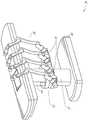
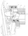
图11提供了台38与柱37之间的接口的详细图示。俯仰旋转机构61可以被配置成以多个自由度改变台38相对于柱37的俯仰角。俯仰旋转机构61可以通过将正交轴线1、2定位在柱台接口处来实现,每条轴线由单独的马达3、4响应于电俯仰角命令而致动。沿一个螺钉5的旋转将使得能够在一条轴线1中进行倾斜调节,而沿另一个螺钉6的旋转将使得能够沿另一个轴线2进行倾斜调节。在一些实施方案中,可使用球形接头来在多个自由度上改变台38相对于柱37的俯仰角。FIG. 11 provides a detailed illustration of the interface between
例如,当试图将台定位在头低脚高位(即,将患者的下腹部定位在比患者的上腹部距地板更高的方位)以用于下腹部手术时,俯仰调节特别有用。头低脚高位致使患者的内部器官通过重力滑向他/她的上腹部,从而清理出腹腔以使微创工具进入并且执行下腹部外科或医疗规程,诸如腹腔镜前列腺切除术。Pitch adjustment is particularly useful, for example, when attempting to position the table in a head-down position (ie, positioning the patient's lower abdomen in an orientation higher from the floor than the patient's upper abdomen) for lower abdominal surgery. The head-down position causes the patient's internal organs to slide by gravity toward his/her upper abdomen, thereby clearing the abdominal cavity to allow minimally invasive tools to enter and perform lower abdominal surgical or medical procedures, such as laparoscopic prostatectomy.
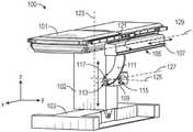
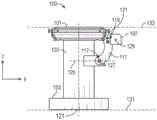
图12和图13示出了基于台的外科机器人系统100的另选实施方案的等轴视图和端视图。外科机器人系统100包括可被配置成相对于台101支撑一个或多个机器人臂(参见例如图14)的一个或多个可调式臂支撑件105。在例示的实施方案中,示出了单个可调式臂支撑件105,但是附加的臂支撑件可设置在台101的相对侧上。可调式臂支撑件105可被配置成使得其可相对于台101运动,以调节和/或改变可调式臂支撑件105和/或安装到该可调式臂支撑件的任何机器人臂相对于台101的方位。例如,可调式臂支撑件105可相对于台101被调节一个或多个自由度。可调式臂支撑件105为系统100提供高灵活性,包括容易地将一个或多个可调式臂支撑件105和附接到其的任何机器人臂收起在台101下方的能力。可调式臂支撑件105可从收起方位升高到台101的上表面下方的方位。在其他实施方案中,可调式臂支撑件105可从收起方位升高到台101的上表面上方的方位。FIGS. 12 and 13 show isometric and end views of an alternate embodiment of a table-based surgical
可调式臂支撑件105可提供若干自由度,包括提升、侧向平移、倾斜等。在图12和图13的例示实施方案中,臂支撑件105被配置成具有四个自由度,这些自由度在图12中用箭头示出。第一自由度允许在z方向上(“Z提升”)调节可调式臂支撑件105。例如,可调式臂支撑件105可包括托架109,该托架被配置成沿或相对于支撑台101的柱102向上或向下运动。第二自由度可允许可调式臂支撑件105倾斜。例如,可调式臂支撑件105可包括旋转接头,该旋转接头可允许可调式臂支撑件105在头低脚高位与床对准。第三自由度可允许可调式臂支撑件105“向上枢转”,这可用于调节台101的一侧与可调式臂支撑件105之间的距离。第四自由度可允许可调式臂支撑件105沿台的纵向长度平移。The
图12和图13中的外科机器人系统100可包括由安装到基部103的柱102支撑的台。基部103和柱102相对于支撑表面支撑台101。地板轴线131和支撑轴线133在图13中示出。The surgical
可调式臂支撑件105可安装到柱102。在其他实施方案中,臂支撑件105可安装到台101或基部103。可调式臂支撑件105可包括托架109、杆或导轨连接件111以及杆或导轨107。在一些实施方案中,安装到轨道107的一个或多个机器人臂可相对于彼此平移和运动。An
托架109可通过第一接头113附接到柱102,该第一接头允许托架109相对于柱102运动(例如,诸如沿第一轴线或竖直轴线123上下运动)。第一接头113可向可调式臂支撑件105提供第一自由度(“Z提升”)。可调式臂支撑件105可包括第二接头115,该第二接头为可调式臂支撑件105提供第二自由度(倾斜)。可调式臂支撑件105可包括第三接头117,该第三接头可为可调式臂支撑件105提供第三自由度(“向上枢转”)。可提供附加接头119(在图13中示出),该附加接头机械地约束第三接头117以在导轨连接件111围绕第三轴线127旋转时保持导轨107的取向。可调式臂支撑件105可包括第四接头121,该第四接头可沿第四轴线129为可调式臂支撑件105提供第四自由度(平移)。
图14示出了根据一个实施方案的具有安装在台101的相对侧上的两个可调式臂支撑件105A、105B的外科机器人系统140A的端视图。第一机器人臂142A附接到第一可调式臂支撑件105B的杆或导轨107A。第一机器人臂142A包括附接到导轨107A的基部144A。第一机器人臂142A的远侧端部包括可附接到一个或多个机器人医疗器械或工具的器械驱动机构146A。类似地,第二机器人臂142B包括附接到导轨107B的基座144B。第二机器人臂142B的远侧端部包括器械驱动机构146B。器械驱动机构146B可被配置成附接到一个或多个机器人医疗器械或工具。14 shows an end view of a surgical
在一些实施方案中,机器人臂142A、142B中的一者或多者包括具有七个或更多个自由度的臂。在一些实施方案中,机器人臂142A、142B中的一者或多者可包括八个自由度,包括插入轴线(包括插入的1个自由度)、腕部(包括腕部俯仰、偏航和翻滚的3个自由度)、肘部(包括肘部俯仰的1个自由度)、肩部(包括肩部俯仰和偏航的2个自由度)以及基部144A、144B(包括平移的1个自由度)。在一些实施方案中,插入自由度可由机器人臂142A、142B提供,而在其他实施方案中,器械本身经由基于器械的插入架构提供插入。In some implementations, one or more of the
C.器械驱动器和接口。C. Instrument Drivers and Interfaces .
系统的机器人臂的端部执行器可包括:(i)器械驱动器(另选地称为“器械驱动机构”或“器械装置操纵器”),该器械驱动器结合了用于致动医疗器械的机电装置;以及(ii)可移除或可拆卸的医疗器械,该医疗器械可以没有任何机电部件,诸如马达。该二分法可能是由以下所驱动的:对医疗规程中使用的医疗器械进行灭菌的需要;以及由于昂贵的资本设备的复杂机械组件和敏感电子器件而不能对昂贵的资本设备进行充分灭菌。因此,医疗器械可以被设计成从器械驱动器(以及因此从系统)拆卸、移除和互换,以便由医师或医师的工作人员单独灭菌或处置。相比之下,器械驱动器不需要被改变或灭菌,并且可以被覆盖以便保护。The end effector of the robotic arm of the system may include: (i) an instrument driver (alternatively referred to as an "instrument drive mechanism" or "instrument device manipulator") that incorporates electromechanical mechanisms for actuating medical instruments device; and (ii) a removable or detachable medical device, which may be devoid of any electromechanical components, such as a motor. This dichotomy may be driven by: the need to sterilize medical devices used in medical procedures; and the inability to adequately sterilize expensive capital equipment due to its complex mechanical components and sensitive electronics . Accordingly, medical instruments can be designed to be detached, removed, and interchanged from the instrument driver (and thus the system) for individual sterilization or disposal by a physician or physician's staff. In contrast, the instrument driver does not need to be altered or sterilized, and can be covered for protection.
图15示出了示例性器械驱动器。定位在机器人臂的远侧端部处的器械驱动器62包括一个或多个驱动单元63,该一个或多个驱动单元以平行轴线布置以经由驱动轴64向医疗器械提供受控扭矩。每个驱动单元63包括用于与器械相互作用的单独的驱动轴64,用于将马达轴旋转转换成期望扭矩的齿轮头65,用于生成驱动扭矩的马达66,用以测量马达轴的速度并且向控制电路提供反馈的编码器67,以及用于接收控制信号并且致动驱动单元的控制电路68。每个驱动单元63被独立地控制和机动化,器械驱动器62可向医疗器械提供多个(例如,如图15所示为四个)独立的驱动输出。在操作中,控制电路68将接收控制信号,将马达信号传输至马达66,将由编码器67测量的所得马达速度与期望速度进行比较,并且调制马达信号以生成期望扭矩。Figure 15 shows an exemplary instrument driver. An
对于需要无菌环境的规程,机器人系统可以结合驱动接口,诸如连接至无菌覆盖件的无菌适配器,其位于器械驱动器与医疗器械之间。无菌适配器的主要目的是将角运动从器械驱动器的驱动轴传递到器械的驱动输入部,同时保持驱动轴与驱动输入部之间的物理分离并且因此保持无菌。因此,示例性无菌适配器可以包括旨在与器械驱动器的驱动轴和器械上的驱动输入部配合的一系列旋转输入部和旋转输出部。连接到无菌适配器的由薄的柔性材料(诸如透明或半透明塑料)组成的无菌覆盖件被设计成覆盖资本设备,诸如器械驱动器、机器人臂和推车(在基于推车的系统中)或台(在基于台的系统中)。覆盖件的使用将允许资本设备被定位在患者附近,同时仍然位于不需要灭菌的区域(即,非无菌区)。在无菌覆盖件的另一侧上,医疗器械可以在需要灭菌的区域(即,无菌区)与患者对接。For procedures requiring a sterile environment, the robotic system may incorporate a drive interface, such as a sterile adapter connected to a sterile cover, between the device driver and the medical device. The main purpose of the sterile adapter is to transmit angular motion from the drive shaft of the instrument driver to the drive input of the instrument, while maintaining the physical separation between the drive shaft and the drive input and thus maintaining sterility. Thus, an exemplary sterile adapter may include a series of rotational inputs and rotational outputs intended to mate with a drive shaft of an instrument driver and a drive input on the instrument. A sterile cover consisting of a thin flexible material (such as clear or translucent plastic) attached to a sterile adapter is designed to cover capital equipment such as instrument drives, robotic arms, and carts (in cart-based systems) or desk (in desk-based systems). The use of a cover would allow capital equipment to be positioned near the patient while still being located in areas that do not require sterilization (ie, non-sterile areas). On the other side of the sterile cover, the medical device can interface with the patient in the area that requires sterilization (ie, the sterile field).
D.医疗器械。D. Medical devices .
图16示出了具有成对器械驱动器的示例性医疗器械。与被设计成与机器人系统一起使用的其他器械类似,医疗器械70包括细长轴71(或细长主体)和器械基部72。由于其用于由医师进行的手动交互的预期设计而也被称为“器械柄部”的器械基部72通常可以包括可旋转驱动输入部73(例如,插座、滑轮或卷轴),该驱动输入部被设计成与延伸通过机器人臂76的远侧端部处的器械驱动器75上的驱动接口的驱动输出部74配合。当物理连接、闩锁和/或耦合时,器械基部72的配合的驱动输入部73可以与器械驱动器75中的驱动输出部74共享旋转轴线,以允许扭矩从驱动输出部74传递到驱动输入部73。在一些实施方案中,驱动输出部74可以包括花键,其被设计成与驱动输入部73上的插座配合。Figure 16 shows an exemplary medical device with paired device drivers. Similar to other instruments designed for use with robotic systems, medical instrument 70 includes an elongated shaft 71 (or elongated body) and an
细长轴71被设计成通过解剖开口或内腔(例如,如在内窥镜检查中)或通过微创切口(例如,如在腹腔镜检查中)递送。细长轴71可以是柔性的(例如,具有类似于内窥镜的特性)或刚性的(例如,具有类似于腹腔镜的特性),或者包括柔性部分和刚性部分两者的定制组合。当被设计用于腹腔镜检查时,刚性细长轴的远侧端部可以连接到端部执行器,该端部执行器从由具有至少一个自由度的连接叉形成的接头腕和外科工具或医疗器械(例如,抓握器或剪刀)延伸,当驱动输入部响应于从器械驱动器75的驱动输出部74接收到的扭矩而旋转时,该外科工具可以基于来自腱的力来致动。当设计用于内窥镜检查时,柔性细长轴的远侧端部可包括可操纵或可控制的弯曲节段,该弯曲节段以基于从器械驱动器75的驱动输出74接收到的扭矩而进行关节运动和弯曲。The elongated shaft 71 is designed to be delivered through an anatomical opening or lumen (eg, as in endoscopy) or through a minimally invasive incision (eg, as in laparoscopy). The elongated shaft 71 may be flexible (eg, having properties similar to an endoscope) or rigid (eg, having properties similar to a laparoscope), or include a custom combination of both flexible and rigid portions. When designed for laparoscopy, the distal end of the rigid elongated shaft may be connected to an end effector from a joint wrist formed by a connecting fork having at least one degree of freedom and a surgical tool or A medical instrument (eg, a grasper or scissors) extends, and the surgical tool can be actuated based on the force from the tendon when the drive input is rotated in response to torque received from the drive output 74 of the instrument driver 75 . When designed for use in endoscopy, the distal end of the flexible elongated shaft may include a steerable or controllable curved section that flexes in response to torque received from the drive output 74 of the instrument driver 75 . Perform articulation and bending.
使用沿着细长轴71的腱沿着细长轴71传递来自器械驱动器75的扭矩。这些单独的腱(例如,牵拉线)可以单独地锚定至器械柄部72内的单独的驱动输入部73。从柄部72,沿着细长轴71的一个或多个牵拉腔向下引导腱并且将其锚定在细长轴71的远侧部分处,或者锚定在细长轴的远侧部分处的腕部中。在外科手术诸如腹腔镜、内窥镜或混合手术期间,这些腱可以耦合到远侧安装的端部执行器,诸如腕部、抓握器或剪刀。在这样的布置下,施加在驱动输入部73上的扭矩将张力传递到腱,从而引起端部执行器以某种方式致动。在一些实施方案中,在外科手术期间,腱可以致使接头围绕轴线旋转,从而致使端部执行器沿一个方向或另一个方向运动。另选地,腱可以连接到细长轴71的远侧端部处的抓握器的一个或多个钳口,其中来自腱的张力致使抓握器闭合。Torque from instrument driver 75 is transmitted along elongated shaft 71 using tendons along elongated shaft 71 . These individual tendons (eg, puller wires) may be individually anchored to individual drive inputs 73 within instrument handle 72 . From the
在内窥镜检查中,腱可以经由粘合剂、控制环或其他机械固定件耦合到沿着细长轴71定位(例如,在远侧端部处)的弯曲或关节运动节段。当固定地附接到弯曲节段的远侧端部时,施加在驱动输入部73上的扭矩将沿腱向下传递,从而引起较软的弯曲节段(有时称为可关节运动节段或区域)弯曲或进行关节运动。沿着不弯曲节段,可以有利的是,使单独的牵拉腔螺旋或盘旋,该牵拉腔沿着内窥镜轴的壁(或在内部)导向单独的腱,以平衡由牵拉线中的张力引起的径向力。为了特定目的,可以改变或设计螺旋的角度和/或它们之间的间隔,其中更紧的螺旋在负载力下表现出较小的轴压缩,而较低的螺旋量在负载力下引起更大的轴压缩,但限制弯曲。在另一种情况下,可以平行于细长轴71的纵向轴线来导向牵拉腔以允许在期望的弯曲或可关节运动节段中进行受控关节运动。In endoscopy, the tendon may be coupled to a flexural or articulation segment positioned along the elongated shaft 71 (eg, at the distal end) via an adhesive, control ring, or other mechanical fixation. When fixedly attached to the distal end of the flexure segment, the torque exerted on the drive input 73 will be transmitted down the tendon, resulting in a softer flexure segment (sometimes referred to as an articulating segment or area) to bend or perform articulation. Along the unbent segment, it may be advantageous to spiral or spiral a separate puller lumen leading along the wall (or inside) of the endoscope shaft to a separate tendon to balance the movement by the puller wire Radial force due to tension in . The angle of the helix and/or the spacing between them can be varied or designed for specific purposes, with tighter helixes exhibiting less axial compression under load force and lower helix amounts causing greater under load force Axial compression, but limited bending. In another instance, the retraction lumen can be directed parallel to the longitudinal axis of the elongated shaft 71 to allow for controlled articulation in the desired bending or articulating segment.
在内窥镜检查中,细长轴71容纳多个部件以辅助机器人规程。轴71可以在轴71的远侧端部处包括用于部署外科工具(或医疗器械)、对手术区域进行冲洗和/或抽吸的工作通道。轴71还可以适应线和/或光纤以向远侧末端处的光学组件/从远侧末端处的光学组件传递信号,该光学组件可以包括光学相机。轴71也可以适应光纤,以将来自位于近侧的光源(例如,发光二极管)的光载送到轴71的远侧端部。In endoscopy, the elongated shaft 71 houses a number of components to assist in robotic procedures. Shaft 71 may include a working channel at the distal end of shaft 71 for deploying surgical tools (or medical instruments), irrigating and/or aspirating the surgical field. The shaft 71 may also accommodate wires and/or optical fibers to transmit signals to/from an optical assembly at the distal tip, which may include an optical camera. The shaft 71 may also accommodate optical fibers to carry light from a proximally located light source (eg, a light emitting diode) to the distal end of the shaft 71 .
在器械70的远侧端部处,远侧末端还可以包括用于递送用于诊断和/或治疗的工具、对手术部位进行冲洗和抽吸的工作通道的开口。远侧末端还可以包括用于相机(诸如纤维镜或数码相机)的端口,以捕获内部解剖空间的图像。相关地,远侧末端还可以包括用于光源的端口,该光源用于在使用相机时照亮解剖空间。At the distal end of the instrument 70, the distal tip may also include an opening for a working channel for delivery of tools for diagnosis and/or therapy, irrigation and aspiration of the surgical site. The distal tip may also include a port for a camera, such as a fiberscope or digital camera, to capture images of the internal anatomical space. Relatedly, the distal tip may also include a port for a light source for illuminating the anatomical space when using the camera.
在图16的示例中,驱动轴轴线以及因此驱动输入部轴线与细长轴71的轴线正交。然而,该布置使细长轴71的滚动能力复杂化。在保持驱动输入部73静止的同时沿着其轴线使细长轴71滚动会引起当腱从驱动输入部73延伸出去并且进入到细长轴71内的牵拉腔时,腱的不期望的缠结。所得到的这样的腱的缠结可能破坏旨在在内窥镜规程期间预测柔性细长轴71的运动的任何控制算法。In the example of FIG. 16 , the drive shaft axis, and thus the drive input axis, is orthogonal to the axis of the elongated shaft 71 . However, this arrangement complicates the rolling capabilities of the elongated shaft 71 . Rolling the elongated shaft 71 along its axis while holding the drive input 73 stationary can cause unwanted entanglement of the tendon as it extends out of the drive input 73 and into the pulling cavity within the elongated shaft 71 Knot. The resulting entanglement of such tendons may disrupt any control algorithms aimed at predicting the motion of the flexible elongated shaft 71 during endoscopic procedures.
图17示出了器械驱动器和器械的另选设计,其中驱动单元的轴线平行于器械的细长轴的轴线。如图所示,圆形器械驱动器80包括四个驱动单元,其驱动输出81在机器人臂82的端部处平行对准。驱动单元和它们各自的驱动输出81容纳在由组件83内的驱动单元中的一个驱动单元驱动的器械驱动器80的旋转组件83中。响应于由旋转驱动单元提供的扭矩,旋转组件83沿着圆形轴承旋转,该圆形轴承将旋转组件83连接到器械驱动器80的非旋转部分84。可以通过电接触将电力和控制信号从器械驱动器80的非旋转部分84传送至旋转组件83,该电接触可以通过电刷滑环连接(未示出)的旋转来保持。在其他实施方案中,旋转组件83可以响应于集成到不可旋转部分84中的单独的驱动单元,并且因此不平行于其他驱动单元。旋转机构83允许器械驱动器80允许驱动单元及其相应的驱动输出81作为单个单元围绕器械驱动器轴线85旋转。Figure 17 shows an alternative design of the instrument driver and instrument in which the axis of the drive unit is parallel to the axis of the elongated shaft of the instrument. As shown, the
与先前所公开的实施方案类似,器械86可以包括细长轴部分88和器械基部87(出于讨论的目的,示出为具有透明的外部表层),该器械基部包括被配置成接收器械驱动器80中的驱动输出部81的多个驱动输入部89(诸如插座、滑轮和卷轴)。与先前公开的实施方案不同,器械轴88从器械基部87的中心延伸,该器械基部的轴线基本上平行于驱动输入部89的轴线,而不是如图16的设计中那样正交。Similar to the previously disclosed embodiments, the
当耦合到器械驱动器80的旋转组件83时,包括器械基部87和器械轴88的医疗器械86与旋转组件83组合地围绕器械驱动器轴线85旋转。由于器械轴88被定位在器械基部87的中心处,因此当附接时器械轴88与器械驱动器轴线85同轴。因此,旋转组件83的旋转致使器械轴88围绕其自身的纵向轴线旋转。此外,当器械基部87与器械轴88一起旋转时,连接到器械基部87中的驱动输入部89的任何腱在旋转期间都不缠结。因此,驱动输出部81、驱动输入部89和器械轴88的轴线的平行允许轴在不会使任何控制腱缠结的情况下旋转。When coupled to the
图18示出了根据一些实施方案的具有基于器械的插入架构的器械。器械150可耦合到上文所述的器械驱动器中的任一个器械驱动器。器械150包括细长轴152、连接到轴152的端部执行器162和耦合到轴152的柄部170。细长轴152包括管状构件,该管状构件具有近侧部分154和远侧部分156。细长轴152沿着其外表面包括一个或多个通道或凹槽158。凹槽158被配置成接纳通过该凹槽的一根或多根线材或缆线180。因此,一根或多根缆线180沿着细长轴152的外表面延伸。在其他实施方案中,缆线180也可穿过细长轴152。所述一根或多根缆线180的操纵(例如,经由器械驱动器)使得端部执行器162的致动。18 illustrates an instrument with an instrument-based insertion architecture, according to some embodiments.
器械柄部170(也可称为器械基部)通常可包括附接接口172,该附接接口具有一个或多个机械输入件174,例如插孔、滑轮或卷轴,所述一个或多个机械输入件被设计成与器械驱动器的附接表面上的一个或多个扭矩耦合器往复地配合。The instrument handle 170 (which may also be referred to as the instrument base) may generally include an
在一些实施方案中,器械150包括使得细长轴152能够相对于柄部170平移的一系列滑轮或缆线。换句话讲,器械150本身包括基于器械的插入架构,该架构适应器械的插入,从而使对机械臂的依赖最小化以提供器械150的插入。在其他实施方案中,机器人臂可以很大程度上负责器械插入。In some embodiments, the
E.控制器。E. Controller .
本文所述的机器人系统中的任一个机器人系统可包括用于操纵附接到机器人臂的器械的输入装置或控制器。在一些实施方案中,控制器可与器械(例如,通信地、电子地、电气、无线地和/或机械地)耦合,使得控制器的操纵例如经由主从控制而致使器械对应操纵。Any of the robotic systems described herein may include an input device or controller for manipulating an instrument attached to the robotic arm. In some embodiments, the controller may be coupled (eg, communicatively, electronically, electrically, wirelessly, and/or mechanically) with the instrument such that manipulation of the controller causes corresponding manipulation of the instrument, eg, via master-slave control.
图19是控制器182的实施方案的透视图。在本实施方案中,控制器182包括可具有阻抗和导纳控制两者的混合控制器。在其他实施方案中,控制器182可仅利用阻抗或被动控制。在其他实施方案中,控制器182可仅利用导纳控制。通过作为混合控制器,控制器182有利地在使用时可具有较低的感知惯性。FIG. 19 is a perspective view of an embodiment of the
在例示的实施方案中,控制器182被配置成允许操纵两个医疗器械,并且包括两个柄部184。柄部184中的每个柄部连接到万向支架186。每个万向支架186连接到定位平台188。In the illustrated embodiment, the
如图19所示,每个定位平台188包括通过棱柱接头196耦合到柱194的SCARA臂(选择顺应性装配机械臂)198。棱柱接头196被配置成沿着柱194(例如,沿着导轨197)平移,以允许柄部184中的每个柄部在z方向上平移,从而提供第一自由度。SCARA臂198被配置成允许柄部184在x-y平面中运动,从而提供两个附加自由度。As shown in FIG. 19 , each
在一些实施方案中,一个或多个负荷传感器定位在控制器中。例如,在一些实施方案中,负荷传感器(未示出)定位在万向支架186中的每个万向支架的主体中。通过提供负荷传感器,控制器182的部分能够在导纳控制下操作,从而在使用时有利地减小控制器的感知惯性。在一些实施方案中,定位平台188被配置用于导纳控制,而万向支架186被配置用于阻抗控制。在其他实施方案中,万向支架186被配置用于导纳控制,而定位平台188被配置用于阻抗控制。因此,对于一些实施方案,定位平台188的平移自由度或方位自由度可依赖于导纳控制,而万向支架186的旋转自由度依赖于阻抗控制。In some embodiments, one or more load sensors are positioned in the controller. For example, in some embodiments, a load sensor (not shown) is positioned in the body of each of the gimbal mounts 186 . By providing a load sensor, portions of the
F.导航和控制。F. Navigation and Control .
传统的内窥镜检查可以涉及使用荧光透视(例如,如可以通过C形臂递送的)和其他形式的基于辐射的成像模态,以向操作医师提供腔内指导。相比之下,本公开所设想的机器人系统可以提供基于非辐射的导航和定位装置,以减少医师暴露于辐射并且减少手术室内的设备的量。如本文所用,术语“定位”可以指确定和/或监测对象在参考坐标系中的方位。诸如术前标测、计算机视觉、实时EM跟踪和机器人命令数据的技术可以单独地或组合地使用以实现无辐射操作环境。在仍使用基于辐射的成像模态的其他情况下,可以单独地或组合地使用术前标测、计算机视觉、实时EM跟踪和机器人命令数据,以改进仅通过基于辐射的成像模态获得的信息。Conventional endoscopy may involve the use of fluoroscopy (eg, as can be delivered by a C-arm) and other forms of radiation-based imaging modalities to provide endoluminal guidance to the operating physician. In contrast, the robotic systems contemplated by the present disclosure may provide non-radiation-based navigation and positioning devices to reduce physician exposure to radiation and reduce the amount of equipment in the operating room. As used herein, the term "positioning" may refer to determining and/or monitoring the orientation of an object in a reference coordinate system. Techniques such as preoperative mapping, computer vision, real-time EM tracking, and robotic command data can be used individually or in combination to achieve a radiation-free operating environment. In other cases where radiation-based imaging modalities are still used, preoperative mapping, computer vision, real-time EM tracking, and robotic command data can be used, alone or in combination, to improve the information obtained only by radiation-based imaging modalities .
图20是示出根据示例性实施方案的估计机器人系统的一个或多个元件的位置(诸如器械的位置)的定位系统90的框图。定位系统90可以是被配置成执行一个或多个指令的一组一个或多个计算机装置。计算机装置可以由上文讨论的一个或多个部件中的处理器(或多个处理器)和计算机可读存储器来体现。以举例的方式而非限制,计算机装置可以位于图1所示的塔30、图1至图4所示的推车11、图5至图14所示的床等中。20 is a block diagram illustrating a
如图20所示,定位系统90可以包括定位模块95,该定位模块处理输入数据91-94以生成用于医疗器械的远侧末端的位置数据96。位置数据96可以是表示器械的远侧端部相对于参考系的位置和/或取向的数据或逻辑。参考系可以是相对于患者解剖结构或已知对象(诸如EM场发生器)的参考系(参见下文对于EM场发生器的讨论)。As shown in FIG. 20, the
现在更详细地描述各种输入数据91-94。术前标测可以通过使用低剂量CT扫描的集合来完成。术前CT扫描被重建为三维图像,该三维图像被可视化,例如作为患者的内部解剖结构的剖面图的“切片”。当总体上分析时,可以生成用于患者的解剖结构(诸如患者肺网络)的解剖腔、空间和结构的基于图像的模型。可以从CT图像确定和近似诸如中心线几何形状的技术,以形成患者解剖结构的三维体积,其被称为模型数据91(当仅使用术前CT扫描生成时也称为“术前模型数据”)。中心线几何形状的使用在美国专利申请14/523,760中有所讨论,其内容全文并入本文中。网络拓扑模型也可以从CT图像中导出,并且特别适合于支气管镜检查。The various input data 91-94 are now described in more detail. Preoperative mapping can be done by using a collection of low-dose CT scans. The preoperative CT scan is reconstructed into a three-dimensional image that is visualized, eg, as a "slice" of a cross-sectional view of the patient's internal anatomy. When analyzed in general, an image-based model of the anatomical cavities, spaces, and structures of the patient's anatomy, such as the patient's lung network, can be generated. Techniques such as centerline geometry can be determined and approximated from CT images to form a three-dimensional volume of the patient's anatomy, which is referred to as model data 91 (also referred to as "pre-operative model data" when generated using only pre-operative CT scans). ). The use of centerline geometry is discussed in US Patent Application 14/523,760, the contents of which are incorporated herein in their entirety. Network topology models can also be derived from CT images and are particularly suitable for bronchoscopy.
在一些实施方案中,器械可以配备有相机以提供视觉数据(或图像数据)92。定位模块95可处理视觉数据92以实现一个或多个基于视觉的(或基于图像的)位置跟踪模块或特征部。例如,术前模型数据91可以与视觉数据92结合使用,以实现对医疗器械(例如,内窥镜或推进通过内窥镜的工作通道的器械)的基于计算机视觉的跟踪。例如,使用术前模型数据91,机器人系统可以基于内窥镜的行进预期路径根据模型生成预期内窥镜图像的库,每个图像连接到模型内的位置。在外科手术进行时,机器人系统可以参考该库,以便将在相机(例如,在内窥镜的远侧端部处的相机)处捕获的实时图像与图像库中的那些图像进行比较,以辅助定位。In some embodiments, the instrument may be equipped with a camera to provide visual data (or image data) 92 . The localization module 95 may process the visual data 92 to implement one or more vision-based (or image-based) position tracking modules or features. For example, preoperative model data 91 may be used in conjunction with visual data 92 to enable computer vision-based tracking of medical instruments (eg, endoscopes or instruments advanced through the working channel of an endoscope). For example, using the preoperative model data 91, the robotic system can generate a library of expected endoscopic images from the model based on the expected path of travel of the endoscope, with each image linked to a location within the model. During surgery, the robotic system can reference this library to compare real-time images captured at a camera (eg, a camera at the distal end of the endoscope) with those in the image library to assist in position.
其他基于计算机视觉的跟踪技术使用特征跟踪来确定相机的运动,并且因此确定内窥镜的运动。定位模块95的一些特征可以识别术前模型数据91中的与解剖腔对应的圆形几何结构并且跟踪那些几何结构的变化以确定选择了哪个解剖腔,以及跟踪相机的相对旋转和/或平移运动。拓扑图的使用可以进一步增强基于视觉的算法或技术。Other computer vision-based tracking techniques use feature tracking to determine the motion of the camera, and thus the endoscope. Some features of the localization module 95 may identify circular geometries in the preoperative model data 91 that correspond to anatomical cavities and track changes in those geometries to determine which anatomical cavity is selected, as well as track relative rotational and/or translational motion of the cameras . The use of topology maps can further enhance vision-based algorithms or techniques.
光流(另一种基于计算机视觉的技术)可以分析视觉数据92中的视频序列中的图像像素的位移和平移以推断相机运动。光流技术的示例可以包括运动检测、对象分割计算、亮度、运动补偿编码、立体视差测量等。通过多次迭代的多帧比较,可以确定相机(以及因此内窥镜)的运动和位置。Optical flow, another computer vision-based technique, can analyze the displacement and translation of image pixels in a video sequence in visual data 92 to infer camera motion. Examples of optical flow techniques may include motion detection, object segmentation calculations, luminance, motion compensated coding, stereo disparity measurement, and the like. Through multiple iterations of multiple frame comparisons, the motion and position of the camera (and therefore the endoscope) can be determined.
定位模块95可以使用实时EM跟踪来生成内窥镜在全局坐标系中的实时位置,该全局坐标系可以被配准到由术前模型表示的患者的解剖结构。在EM跟踪中,包括嵌入在医疗器械(例如,内窥镜工具)中的一个或多个位置和取向中的一个或多个传感器线圈的EM传感器(或跟踪器)测量由定位在已知位置处的一个或多个静态EM场发生器产生的EM场的变化。由EM传感器检测的位置信息被存储为EM数据93。EM场发生器(或发射器)可以靠近患者放置,以产生嵌入式传感器可以检测到的低强度磁场。磁场在EM传感器的传感器线圈中感应出小电流,可以对该小电流进行分析以确定EM传感器与EM场发生器之间的距离和角度。这些距离和取向可以在外科手术进行时“配准”到患者解剖结构(例如,术前模型),以确定将坐标系中的单个位置与患者的解剖结构的术前模型中的方位对准的几何变换。一旦配准,医疗器械的一个或多个方位(例如,内窥镜的远侧末端)中的嵌入式EM跟踪器可以提供医疗器械通过患者的解剖结构的进展的实时指示。The localization module 95 can use real-time EM tracking to generate the real-time position of the endoscope in a global coordinate system that can be registered to the patient's anatomy as represented by the preoperative model. In EM tracking, an EM sensor (or tracker) that includes one or more sensor coils embedded in one or more positions and orientations in a medical instrument (eg, an endoscopic tool) measures by being positioned at a known location Variation in the EM field produced by one or more static EM field generators at . The position information detected by the EM sensor is stored as
机器人命令和运动学数据94也可以由定位模块95使用以提供用于机器人系统的方位数据96。可以在术前校准期间确定从关节运动命令得到的装置俯仰和偏航。在外科手术进行时,这些校准测量可以与已知的插入深度信息结合使用,以估计器械的方位。另选地,这些计算可以结合EM、视觉和/或拓扑建模进行分析,以估计医疗器械在网络内的方位。Robot commands and
如图20所示,定位模块95可以使用多个其他输入数据。例如,尽管在图20中未示出,但是利用形状感测纤维的器械可以提供定位模块95可以用来确定器械的位置和形状的形状数据。As shown in Figure 20, a number of other input data may be used by the positioning module 95. For example, although not shown in Figure 20, an instrument utilizing shape sensing fibers may provide shape data that the positioning module 95 may use to determine the position and shape of the instrument.
定位模块95可以组合地使用输入数据91-94。在一些情况下,这样的组合可以使用概率方法,其中定位模块95向根据输入数据91-94中的每个输入数据确定的位置分配置信度权重。因此,在EM数据可能不可靠(如可能存在EM干扰的情况)的情况下,由EM数据93确定的位置的置信度可能降低,并且定位模块95可能更重地依赖于视觉数据92和/或机器人命令和运动学数据94。Positioning module 95 may use input data 91-94 in combination. In some cases, such a combination may use a probabilistic approach, wherein the location module 95 assigns a confidence weight to the location determined from each of the input data 91-94. Thus, where the EM data may be unreliable (eg, where EM interference may exist), the confidence in the location determined by the
如上所讨论的,本文讨论的机器人系统可以被设计成结合以上技术中的一种或多种技术的组合。位于塔、床和/或推车中的机器人系统的基于计算机的控制系统可以将计算机程序指令存储在例如非暂态计算机可读存储介质(诸如永久性磁存储驱动器、固态驱动器等)内,该计算机程序指令在执行时致使系统接收并且分析传感器数据和用户命令,生成整个系统的控制信号并且显示导航和定位数据,诸如器械在全局坐标系内的方位、解剖图等。As discussed above, the robotic systems discussed herein may be designed to incorporate one or a combination of the above techniques. The computer-based control system of the robotic system located in the tower, bed, and/or cart may store computer program instructions, for example, in a non-transitory computer-readable storage medium (such as a persistent magnetic storage drive, a solid-state drive, etc.), which The computer program instructions, when executed, cause the system to receive and analyze sensor data and user commands, generate control signals for the entire system, and display navigation and positioning data, such as instrument orientation within a global coordinate system, anatomical maps, and the like.
2.利用共享机器人自由度(DoF)进行运动学优化的系统和方法的简介。2. Introduction to systems and methods for kinematic optimization using shared robot degrees of freedom (DoF) .
本公开涉及用于利用共享机器人DoF进行运动学优化的系统和技术。在一些实施方案中,本公开涉及用于利用共享机器人臂DOF碰撞避免的系统和技术。机器人臂可用于实现医疗工具的端部执行器的期望位姿(即,位置和取向)。在一些实施方案中,医疗工具可以包括医疗器械或相机。在操纵机器人臂以实现期望的端部执行器位姿时,可能存在机器人臂的一些部分移动成与另一附近对象(例如,另一机器人臂、患者、支撑患者的平台、附接到平台的医疗附件等)碰撞的位姿的风险。The present disclosure relates to systems and techniques for kinematic optimization with shared robot DoF. In some embodiments, the present disclosure relates to systems and techniques for DOF collision avoidance utilizing a shared robotic arm. The robotic arm can be used to achieve the desired pose (ie, position and orientation) of the end effector of the medical tool. In some embodiments, the medical tool may include a medical instrument or a camera. When manipulating the robotic arm to achieve the desired end effector pose, there may be parts of the robotic arm that move into contact with another nearby object (eg, another robotic arm, a patient, a platform supporting the patient, a Medical accessories, etc.) risk of colliding poses.
避免机器人臂碰撞的一种方式是例如在执行医疗规程之前定位机器人臂和接入点,以使得机器人臂不太可能被放置成将导致碰撞的位姿。然而,预规程放置或定位可能限制机器人臂放置和/或接入点放置的选项。例如,机器人臂和接入点可以间隔最小距离,以便减小其间碰撞的可能性。然而,机器人臂和/或接入点的此类间隔可能降低用户将医疗工具定位在期望位姿中的能力。例如,某些大小的患者(例如,较小的患者)的某些规程可能涉及关闭端口间隔以形成进入患者的解剖结构的接入点。在这些情况下,可能无法将机器人臂和/或接入点放置在降低机器人臂碰撞的可能性的位置。One way to avoid collisions of the robotic arms is to position the robotic arms and access points, such as before performing medical procedures, so that the robotic arms are less likely to be placed in poses that would result in a collision. However, pre-procedure placement or positioning may limit options for robotic arm placement and/or access point placement. For example, the robotic arm and the access point can be separated by a minimum distance to reduce the likelihood of collisions between them. However, such spacing of robotic arms and/or access points may reduce a user's ability to position the medical tool in a desired pose. For example, certain procedures for patients of certain sizes (eg, smaller patients) may involve closing the port spacers to form access points into the patient's anatomy. In these cases, it may not be possible to place the robotic arm and/or access point in a location that reduces the likelihood of a robotic arm collision.
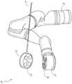
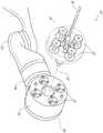
图21示出了根据本公开的各方面的示例性机器人臂100。机器人臂100包括由一个或多个接头110连接的多个连接件105。机器人臂100的近侧端部可以连接到基座115,并且机器人臂100的远侧端部可以连接到高级装置操纵器(ADM)120(也称为端部执行器)。ADM120可以被配置成控制医疗工具125(也称为医疗器械)的定位和操纵。因此,连接件105可以可拆卸地耦合到医疗工具125。接头110向机器人臂100提供多个DoF,所述多个DoF促进经由ADM 120控制医疗工具125。21 illustrates an exemplary
在医疗规程期间,可能期望机器人臂100的ADM 120和/或与其耦合的工具125的远程移动中心(RCM)保持在静态位姿/位置。RCM可以指空间中的点,其中插入医疗工具125的套管或其它进入端口被限制在运动中。在一些实施方案中,医疗工具125包括端部执行器,所述端部执行器通过患者的切口或自然孔口插入,同时保持RCM。During a medical procedure, it may be desirable for the
在一些情况下,机器人系统可以被配置成在“零空间”内移动机器人臂100的一个或多个连接件105,以避免与附近对象(例如,其它机器人臂)碰撞,而机器人臂100和/或RCM的ADM 120保持在其相应的位姿/位置。零空间可以被视为机器人臂100可以移动的空间,所述空间不会导致ADM 120和/或RCM移动,从而保持医疗工具125的位置和/或取向。在一些实施方案中,机器人臂100可以具有可用于ADM 120的每个位姿的多个位置和/或配置。In some cases, the robotic system may be configured to move one or
对于将ADM 120移动到空间中的期望位姿的机器人臂100,在某些实施方案中,机器人臂100可以具有至少六个DoF-三个DoF用于平移(例如,X、Y、Z位置)和三个DoF用于旋转(例如,偏航、俯仰和滚动)。在一些实施方案中,每个接头110可以提供具有单个DoF的机器人臂100,并且因此,机器人臂100可以具有至少六个接头以实现将ADM 120定位在空间中的任何位姿的运动自由度。为了进一步将机器人臂100的ADM 120和/或远程中心或运动保持在期望的位姿,机器人臂100可以进一步具有至少一个附加的“冗余接头”。因此,在某些实施方案中,系统可以包含具有至少七个接头110的机器人臂100,其提供具有至少七个DoF的机器人臂100。然而,取决于实施方式,机器人臂100可以具有更多或更少数量的DoF。For the
具有至少一个冗余DoF的机器人臂100可以指机器人臂100可以比用于执行给定任务的最小DoF数量多至少一个DoF。例如,机器人臂100可以具有至少七个DoF,其中机器人臂100的接头100中的一个可以被认为是冗余接头。一个或多个冗余接头可以允许机器人臂100在零空间中移动以保持ADM 120的位姿和RCM的位置,并且避免与其它臂或对象的碰撞。A
一种机器人系统(例如,图6的系统36或图14的系统140A)可以被配置成通过利用一个或多个冗余接头在零空间中的移动来执行碰撞避免以避免例如相邻机器人臂之间的碰撞。例如,当机器人臂与另一机器人臂碰撞或接近(例如,在限定的距离内)时,系统的一个或多个处理器可以被配置成检测碰撞或即将发生碰撞(例如,通过运动学)。因此,该系统可以控制一个或两个机器人臂在零空间内调整各自的接头,以避免碰撞或即将发生的碰撞。在涉及一对机器人臂的一个实施方式中,机器人臂和其端部执行器中的一个的基座可以保持其位姿,而其间的连接件或接头在零空间中移动以避免与相邻机器人臂碰撞。A robotic system (eg,
在某些实施方案中,机器人系统可以使用机器人臂中的冗余接头作为唯一零空间DoF。当系统只有一个零空间运动的DoF时,零空间可以是一条穿过空间的一维线。如果零空间线使一个或多个机器人臂通过无效位姿或发生碰撞,则系统可能无法为某些ADM位姿和/或RCM位置提供零空间调整和避免碰撞。In some embodiments, the robotic system may use redundant joints in the robotic arm as the only null-space DoF. When the system has only one DoF of null-space motion, the null-space can be a one-dimensional line through the space. If the null-space line causes one or more robot arms to pass through invalid poses or collide, the system may not be able to provide null-space adjustments and collision avoidance for some ADM poses and/or RCM positions.
本公开的各方面涉及使用来自不同类型的机器人部件的DoF用于运动学优化,例如避免碰撞。特别地,本公开的某些方面涉及使用在不同机器人部件之间共享的机器人医疗系统的DoF的碰撞避免。如本文所用,共享DoF可以指影响至少两个独立的端部执行器的位姿的DoF。例如,机器人系统可以包含可调式臂支撑件,一个或多个机器人臂支撑在所述可调式臂支撑件上。可调式臂支撑件可以具有与由可调式臂支撑件支撑的机器人臂共享的DoF。在另一示例中,机器人系统可以包含可调患者平台,所述可调患者平台可在一个或多个DoF中移动,所述DoF与耦合到支撑患者平台的支撑结构的一个或多个机器人臂共享。Aspects of the present disclosure relate to using DoFs from different types of robotic components for kinematic optimization, such as collision avoidance. In particular, certain aspects of the present disclosure relate to collision avoidance of DoFs using robotic medical systems that are shared among different robotic components. As used herein, a shared DoF may refer to a DoF that affects the pose of at least two independent end effectors. For example, a robotic system may include an adjustable arm support on which one or more robotic arms are supported. The adjustable arm support may have a DoF that is shared with the robotic arm supported by the adjustable arm support. In another example, a robotic system may include an adjustable patient platform movable in one or more DoFs shared with one or more robotic arms coupled to a support structure supporting the patient platform .
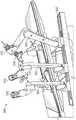
图22示出了根据本公开的方面的包括可调式臂支撑件210的机器人系统200的示例。参考图22,机器人系统200包括多个机器人臂205、一个或多个可调式臂支撑件210、一个或多个装配接头215和床柱220。机器人臂205中的每一个可以由可调式臂支撑件210中的一个支撑,并且可调式臂支撑件210可以继而由装配接头215支撑。如上所述,每个机器人臂205可以具有多个DoF。类似地,可调式臂支撑件210和装配接头215可以在一个或多个DoF中移动。22 shows an example of a
图23示意性地示出了一个或多个DoF如何在机器人臂、可调式臂支撑件和装配接头之间共享。图23示出了系统300,其中装配接头310可以在近侧端部处耦合到床支撑件305并且在远侧端部处耦合到可调式臂支撑件310。此外,多个机器人臂320可以在其相应的近侧端部处耦合到可调式臂支撑件315。在某些实施方案中,可调式臂支撑件315和装配接头310一起可以具有四个DoF。因此,附接到可调式臂支撑件315的机器人臂320可以共享由装配接头310和可调式臂支撑件315提供的四个DoF。Figure 23 schematically shows how one or more DoFs are shared between the robotic arm, the adjustable arm support and the assembly joint. Figure 23 shows a
包括根据本公开的各方面的可调式臂支撑件105的机器人系统100的另一个示例在图12中示出。可调式臂支撑件105可提供若干自由度,包括提升、侧向平移、倾斜等。在图12的例示实施方案中,臂支撑件105被配置成具有四个自由度,这些自由度在图12中用箭头示出。第一自由度允许在z方向上(“Z提升”)调节可调式臂支撑件105。例如,可调式臂支撑件105可包括托架109,该托架被配置成沿或相对于支撑台101的柱102向上或向下运动。第二自由度可允许可调式臂支撑件105倾斜。例如,可调式臂支撑件105可包括旋转接头,该旋转接头可允许可调式臂支撑件105在头低脚高位与床对准。第三自由度可允许可调式臂支撑件105“向上枢转”,这可用于调节台101的一侧与可调式臂支撑件105之间的距离。第四自由度可允许可调式臂支撑件105沿台的纵向长度平移。Another example of a
托架109可通过第一接头113附接到柱102,该第一接头允许托架109相对于柱102运动(例如,诸如沿第一轴线或竖直轴线上下运动)。第一接头113可向可调式臂支撑件105提供第一自由度(“Z提升”)。可调式臂支撑件105可包括第二接头115,该第二接头为可调式臂支撑件105提供第二自由度(倾斜)。可调式臂支撑件105可包括第三接头117,该第三接头可为可调式臂支撑件105提供第三自由度(“向上枢转”)。可提供附加接头(未示出),该附加接头机械地约束第三接头117以在导轨连接件111围绕第三轴线旋转时保持导轨107的取向。可调式臂支撑件105可包括第四接头121,该第四接头可沿第四轴线为可调式臂支撑件105提供第四自由度(平移)。
因此,取决于实施方式,机器人医疗系统可以具有超过机器人臂中的那些的许多机器人控制的自由度,以提供零空间移动和碰撞避免。在这些实施方式中的每个实施方式中,一个或多个机器人臂的端部执行器(以及与其耦合的任何工具或仪器)和/或与其相关联的工具的远程中心可以有利地维持患者体内的位姿和/或位置。Thus, depending on the implementation, the robotic medical system may have many robotically controlled degrees of freedom beyond those in the robotic arms to provide zero-space movement and collision avoidance. In each of these embodiments, a remote center of one or more robotic arms' end effectors (and any tools or instruments coupled thereto) and/or tools associated therewith may advantageously maintain a patient's body pose and/or position.
A.使用共享机器人DoF在连接件构件之间进行零空间移动。A. Use the shared robot DoF for zero-space movement between connector components .
本公开的方面涉及机器人系统和方法,其利用不同连接件构件(例如,多个机器人臂和/或可调式臂支撑件的)之间的共享DoF来实现零空间移动以避免碰撞。在某些实施方案中,该系统可以使用与第一组一个或多个机动连接件(例如,以一个或多个机械臂的形式——例如,图22中所示的机器人臂205)相关联的一个或多个DoF与同第二组一个或多个机动连接件(例如,以支撑机器人臂的支撑连接件的形式,包括一个或多个装配接头连接件和一个或多个臂支撑连接件——例如,图22中所示的装配接头215和可调式臂支撑件210)相关联的一个或多个DoF进行协调和/或同步运动,以实现零空间移动以避免碰撞。Aspects of the present disclosure relate to robotic systems and methods that utilize a shared DoF between different linker components (eg, of multiple robotic arms and/or adjustable arm supports) to achieve zero-space movement to avoid collisions. In certain embodiments, the system may be used in association with a first set of one or more motorized linkages (eg, in the form of one or more robotic arms—eg,
第一组一个或多个机动连接件(例如,以一个或多个机器人臂的形式)可以被配置成执行与第二组一个或多个机动连接件(例如,以支撑连接件或导轨的形式)不同的功能。在一些实施方案中,第一组一个或多个连接件由第二组一个或多个连接件支持。A first set of one or more motorized links (eg, in the form of one or more robotic arms) may be configured to perform communication with a second set of one or more motorized links (eg, in the form of support links or rails) ) different functions. In some embodiments, the first set of one or more connectors is supported by the second set of one or more connectors.
此外,在一些实施方案中,第一组一个或多个机动连接件具有与第二组一个或多个机动连接件不同数量的DoF。例如,在如图23所示的简化实施方式中所示,第一组一个或多个连接件可以形成三个机器人臂320,每个机器人臂具有7个或更多个DoF。例如,机器人臂320中的每一个可以具有DoF,该DoF包括但不限于肩部偏航、肩部俯仰、肘部俯仰、腕部偏航、腕部俯仰、滚动和插入。第二组一个或多个机动连接件可以与具有4个或更多个DoF的可调式臂支撑件315组合形成装配接头310。例如,装配接头310和可调式臂支撑件315可以具有DoF,包括但不限于垂直平移或“Z提升”,沿床的纵向平移、倾斜和向上枢转。装配接头310和可调式臂支撑件315的DoF也被示出在图24中,如上文所论述。Furthermore, in some embodiments, the first set of one or more motorized links has a different number of DoFs than the second set of one or more motorized links. For example, as shown in the simplified embodiment shown in Figure 23, a first set of one or more links may form three
在其它实施方式中,第一组一个或多个机动连接件可以具有与第二组一个或多个机动连接件相同数量的DoF。有利地,通过在具有DoF的第一组一个或多个连接件和第二组一个或多个连接件之间共享DoF,可以扩大用于零空间移动和避免碰撞的DoF的数量。In other embodiments, the first set of one or more motorized links may have the same number of DoFs as the second set of one or more motorized links. Advantageously, by sharing the DoF between a first set of one or more links with a DoF and a second set of one or more links, the number of DoFs for null space movement and collision avoidance can be expanded.
本公开的方面涉及机器人系统,除了能够进行零空间移动的机器人臂的DoF之外,还具有一个或多个DoF。这些额外的DoF(例如,来自装配接头与可调式臂支撑件组合)可以影响耦合到可调式臂支撑件的机器人臂的运动并且有助于避免碰撞。例如,当与每个机器人臂中的每一个的DoF组合时,来自第二组连接件的DoF包括竖直平移、纵向平移和倾斜对于零空间移动特别有用。Aspects of the present disclosure relate to robotic systems having one or more DoFs in addition to the DoF of a robotic arm capable of zero-space movement. These additional DoFs (eg, from the assembly joint in combination with the adjustable arm support) can affect the motion of the robotic arm coupled to the adjustable arm support and help avoid collisions. For example, when combined with the DoF for each of the robotic arms, the DoF from the second set of links including vertical translation, longitudinal translation and tilt is particularly useful for zero space movement.
在上述实施方式中,不同组的连接件构件之间的共享DoF用于零空间移动,由此至少一组连接件构件与机器人臂相关联。在这些实施方案中,机器人臂的ADM以及附接到其的工具的RCM可以有利地保持在适当位姿/位置。In the above-described embodiments, the shared DoF between the different sets of linker members is used for zero-space movement, whereby at least one set of linker members is associated with the robotic arm. In these embodiments, the ADM of the robotic arm and the RCM of the tool attached thereto can advantageously be held in the proper pose/position.
图24A和24B示出了根据本公开的各方面在保持ADM和RCM位姿/位置的同时两组连接件的移动。具体地说,图25A示出了机器人系统500,该机器人系统包括由第一组连接件形成的多个机器人臂505,第一组连接件各自具有被配置成控制医疗工具515的移动的ADM510。机器人臂505由可调式臂支撑件520和由第二组连接件形成的装配接头(未示出)支撑。图24A示出机器人臂505、ADM 510、医疗工具515和可调式臂支撑件中的每一者在第一时间点的位姿。24A and 24B illustrate the movement of two sets of links while maintaining ADM and RCM poses/positions in accordance with aspects of the present disclosure. Specifically, FIG. 25A shows a
图24B示出了图24A的机器人系统500在第一组连接件和第二组连接件已经在零空间中移动之后的第二时间点。从图24A和24B的比较中可以看出,在机器人臂505和可调式臂支撑件520在零空间中移动的同时,保持每个ADM和医疗工具515的位姿(包括位置和旋转)。第一组连接件与第二组连接件之间的共享DoF允许机器人臂505、可调式臂支撑件520和装配接头中的一个或多个的零间空间移动,同时保持ADM和医疗工具515的RCM的位姿/位置。因此,该系统能够保持机器人臂505的ADM 510和医疗工具515的位姿,即使在第一组连接件构件(例如,机器人臂505)和第二组连接件构件(例如,装配接头和可调式臂支撑件520)之间存在移动(例如,通过共享DoF)。24B shows the
图25是示出根据本公开的各方面的能够由机器人系统或其部件操作的示例方法的流程图,用于使用共享的机器人DoF在连接件构件之间进行零空间移动。例如,图25中所示的方法600的某些步骤可由医疗机器人系统(例如,机器人使能系统10)或相关联的系统的处理器和/或其他部件执行。为方便起见,方法600被描述为由“系统”结合方法600的描述来执行。25 is a flowchart illustrating an example method operable by a robotic system or components thereof for zero-space movement between connector members using a shared robotic DoF in accordance with aspects of the present disclosure. For example, certain steps of
方法600在框601处开始。在框605处,方法600可以涉及提供包括耦合到一对机器人臂的可调式臂支撑件的医疗平台。每个机器人臂可以耦合到医疗工具。例如,医疗平台可以是图22中所示的系统200、图12中所示的系统100、图24A和图24B中所示的系统500或者图22中所示的系统200的一部分。
在框610处,系统可以调整可调式臂支撑件和耦合到其的机器人臂中的每个机器人臂的位置,同时保持每个工具的RCM。例如,如图24A和24B中所示,系统可以移动可调式臂支撑件520和耦合到其的机器人臂505,同时保持医疗工具515的RCM。方法600在框615处结束。At
图26是示出根据本公开的各方面的能够由机器人系统或其部件操作的另一示例方法的流程图,用于使用共享的机器人DoF在连接件构件之间进行零空间移动。例如,图26所示的方法700的步骤可由医疗机器人系统(例如,机器人使能系统10)或相关联的系统的处理器和/或其他部件执行。为方便起见,方法700被描述为由“系统”结合方法700的描述来执行。26 is a flowchart illustrating another example method operable by a robotic system or components thereof for zero-space movement between connector members using a shared robotic DoF, in accordance with aspects of the present disclosure. For example, the steps of
方法700在框701处开始。在框705处,系统可以移动第一组一个或多个连接件以执行第一任务。第一组一个或多个连接件可以具有至少一个DoF。在框710处,系统可以移动第二组一个或多个连接件以执行不同于第一任务的第二任务。第二组一个或多个连接件还可以具有至少一个DoF。第一组一个或多个连接件和第二组一个或多个连接件中的每一者的至少一个DoF是共享的。
在框715处,系统可以使用共享的至少一个DoF在零空间中移动第一组一个或多个连接件和第二组一个或多个连接件中的至少一者。在一些实施方案中,在零空间中移动第一组连接件可以涉及改变第一组一个或多个连接件的配置(例如,位姿),同时保持一个或多个机器人臂的端部执行器的位置。方法700在框720处结束。At
在方法700的一些实施方案中,第一组一个或多个连接件可以包括一个或多个机器人臂(例如,至少三个机器人臂),并且第二组一个或多个连接件可以形成支撑连接件。系统可以移动机器人臂和/或支撑连接件,以避免臂与另一对象之间的碰撞(例如,环境中的另一机器人臂或其它对象)。这种避免碰撞可能涉及系统确定一个或多个机器人臂中的一个或多个的移动将机器人臂中的至少一个定位在工作空间中对象的阈值距离内。系统可以进一步命令以下中的至少一个的移动:(i)至少三个机器人臂和(ii)零空间中的第二组一个或多个连接件以减小涉及至少一个机器人臂和工作空间内的对象的碰撞的可能性。In some embodiments of
在某些实施方案中,方法700可以进一步涉及保持与第一组一个或多个连接件耦合的医疗工具的RCM的位置,同时在第一组一个或多个DoF中移动第一组一个或多个连接件。例如,可能期望保持RCM,使得医疗工具不会对患者的身体壁施加不必要的力。在一些实施方案中,保持RCM可以涉及保持医疗工具相对于手术台的RCM。方法700可以进一步涉及在移动至少一个第二DoF中的第二组一个或多个连接件时保持RCM的位置,从而允许第二组一个或多个连接件的零空间移动。In certain embodiments,
在某些实施方案中,使用共享DoF之间的至少一个机器人臂和可调式臂支撑件之间的零空间移动也可以由机器人医疗系统执行,机器人医疗系统包括基座、耦合到基座的可调式臂支撑件,以及耦合到可调式臂支撑件的至少一个机器人臂。至少一个机器人臂可以被配置成耦合到医疗工具,该医疗工具被配置成通过患者的切口或自然孔口递送(例如,如图24A和24B所示)。系统可以进一步包括处理器,该处理器被配置成调整可调式臂支撑件和至少一个机器人臂的位置,同时保持工具的RCM。当系统包括两个或更多个机器人臂时,处理器可以被配置成调整可调式臂支撑件和机器人臂中的每个机器人臂的位置,同时保持工具中的每个工具的RCM。通过同时调整可调式臂支撑件和机器人臂的位置,系统可利用由机器人臂与可调式臂支撑件之间的至少一个共享DoF提供的零空间来保持工具的RCM。In certain embodiments, zero-space movement between the at least one robotic arm and the adjustable arm support using shared DoFs may also be performed by a robotic medical system comprising a base, an adjustable arm coupled to the base An adjustable arm support, and at least one robotic arm coupled to the adjustable arm support. At least one robotic arm can be configured to be coupled to a medical tool configured to be delivered through a patient's incision or natural orifice (eg, as shown in Figures 24A and 24B). The system may further include a processor configured to adjust the position of the adjustable arm support and the at least one robotic arm while maintaining the RCM of the tool. When the system includes two or more robotic arms, the processor may be configured to adjust the position of the adjustable arm support and each of the robotic arms while maintaining the RCM of each of the tools. By simultaneously adjusting the positions of the adjustable arm support and the robotic arm, the system can maintain the RCM of the tool using the null space provided by at least one shared DoF between the robotic arm and the adjustable arm support.
处理器可以进一步被配置成调整可调式臂支撑件和至少一个机器人臂的位置,同时保持耦合到至少一个机器人臂的工具的端部执行器的位置。在一些实施方案中,处理器可以被进一步配置成调整机器人臂和/或可调式臂支撑件的位置,工具的远侧端部的位置由临床医生控制。例如,处理器可以在工具由临床医生远程操作地控制时调整可调式臂支撑件的位置。The processor may be further configured to adjust the position of the adjustable arm support and the at least one robotic arm while maintaining the position of the end effector of the tool coupled to the at least one robotic arm. In some embodiments, the processor may be further configured to adjust the position of the robotic arm and/or the adjustable arm support, the position of the distal end of the tool being controlled by the clinician. For example, the processor may adjust the position of the adjustable arm support while the tool is being remotely controlled by the clinician.
系统可以进一步被配置成移动机器人臂和可调式臂支撑件中的一者或多者以避免碰撞。例如,某些命令的工具位置可以使机器人臂中的一个机器人臂与另一个机器人臂碰撞或环境中的另一对象碰撞。由于由机器人臂、可调式臂支撑件和/或装配接头提供的附加或冗余DoF允许在零空间内移动(例如,不改变工具的端部执行器的位置和远程中心或移动),因此系统可以移动机器人臂、可调式臂支撑件和装配接头中的一者或多者以避免潜在碰撞。因此,在一些实施方案中,处理器可以被配置成调整可调式臂支撑件和至少一个机器人臂的位置,以便在至少一个机器人与周围对象之间提供碰撞避免。The system may be further configured to move one or more of the robotic arm and the adjustable arm support to avoid collisions. For example, certain commanded tool positions can cause one of the robotic arms to collide with another robotic arm or another object in the environment. Since the additional or redundant DoF provided by the robotic arm, adjustable arm supports, and/or assembly joints allows movement in zero space (eg, without changing the position and remote centering or movement of the tool's end effector), the system One or more of the robotic arm, the adjustable arm support, and the assembly joint may be moved to avoid potential collisions. Accordingly, in some embodiments, the processor may be configured to adjust the position of the adjustable arm support and the at least one robotic arm to provide collision avoidance between the at least one robot and surrounding objects.
某些命令的机器人臂移动或位置可能导致臂靠近或穿过奇点。奇点可以指机器人失去有效自由度的位姿,例如当两个轴对齐时。为了避免这种奇点,处理器可以被配置成确定命令的移动是否会导致或使机器人臂更接近奇点,并通过零空间移动避免奇点。具体地,处理器可以被配置成调整可调式臂支撑件和机器人臂的位置,以避免机器人臂中的一个或多个奇点。Certain commanded robot arm movements or positions may cause the arm to approach or pass through the singularity. A singularity can refer to a pose where the robot loses effective degrees of freedom, such as when two axes are aligned. To avoid such a singularity, the processor may be configured to determine whether the commanded movement would cause or bring the robotic arm closer to the singularity, and to avoid the singularity by moving in null space. Specifically, the processor may be configured to adjust the position of the adjustable arm support and the robotic arm to avoid one or more singularities in the robotic arm.
在一些实施方案中,系统还可以被配置成在医疗规程的不同阶段之间移动多个连接件。某些医疗规程可能涉及在患者的不同区域中发生的不同阶段。例如,患者的腹部可以被分成四个区域或象限。因此,该系统可以被配置成促进多个机器人臂在规程的第一阶段期间的第一象限与规程的第二阶段期间的第二象限之间的移动。因此,系统可以被配置成使用患者的第一象限中的医疗工具移动第一组一个或多个连接件以执行医疗规程的第一阶段。系统还可以在零空间中移动第一组连接件和第二组一个或多个连接件,使得医疗工具能够访问患者的第二象限。系统还可以被配置成使用所述患者的第二象限中的医疗工具移动第一组一个或多个连接件以执行医疗程序的第二阶段。零空间中的这种移动可以允许系统自动移动连接件(例如,机器人臂),使得用户能够在不同阶段期间访问患者的不同象限,而无需手动重新定位连接件所需的认知负荷。In some embodiments, the system can also be configured to move multiple connectors between different stages of a medical procedure. Certain medical procedures may involve different stages that occur in different areas of the patient. For example, a patient's abdomen may be divided into four regions or quadrants. Accordingly, the system may be configured to facilitate movement of the plurality of robotic arms between a first quadrant during the first phase of the procedure and a second quadrant during the second phase of the procedure. Accordingly, the system may be configured to move the first set of one or more connectors using the medical tool in the first quadrant of the patient to perform the first stage of the medical procedure. The system may also move the first set of connectors and the second set of one or more connectors in null space to enable the medical tool to access the second quadrant of the patient. The system may also be configured to use the medical tool in the second quadrant of the patient to move the first set of one or more connectors to perform the second stage of the medical procedure. This movement in null space may allow the system to automatically move the connector (eg, a robotic arm), enabling the user to access different quadrants of the patient during different phases without the cognitive load required to manually reposition the connector.
B.使用共享机器人DoF在连接件构件与患者定位平台之间进行零空间移动。B. Zero space movement between the connector member and the patient positioning platform using the shared robot DoF .
在一些实施方案中,机器人系统可以进一步包括具有至少一个DoF的患者定位平台。根据本公开的各方面的包括患者定位平台225的机器人系统200的另一个示例在图22中示出。系统200包括患者定位平台225、多个机器人臂205、可调式臂支撑件210和装配接头215。In some embodiments, the robotic system may further include a patient positioning platform with at least one DoF. Another example of a
在图22所示的具体实施中,系统200可以为与第一组一个或多个机动连接件(例如,以一个或多个机器人臂205的形式)相关联的一个或多个DoF之间的零空间移动提供共享机器人DoF,与同患者定位平台225(例如,以床的形式)相关联的一个或多个DoF进行协调和/或同步运动。例如,在一些具体实施中,患者定位平台225可以具有三个或更多个DoF,包括垂直平移、侧向倾斜和特伦德伦伯卧位倾斜。然而,在其它具体实施中,患者定位平台可以具有多于或少于三个DoF。In the implementation shown in FIG. 22 , the
如在上述具体实施中,涉及在第一组连接件(例如,机器人臂205的)和第二组连接件(例如,装配接头和可调式臂支撑件210的)之间的共享DoF,在图22所示的系统200中,系统可以保持机器人臂205的ADM的位姿和/或任何相关联的医疗工具的远程移动中心,同时机器人臂205与患者定位平台225之间的共享DoF提供零空间移动。As in the above-described implementation, involving a shared DoF between a first set of connectors (eg, of the robotic arm 205 ) and a second set of connectors (eg, of the assembly joints and the adjustable arm support 210 ), shown in FIG. In the
从系统的角度来看,整个系统200可以被分配成不同的机器人分区。例如,用于患者定位的DoF(例如,与患者定位平台225的床倾斜、特伦德伦伯卧位等相关的DoF)可以被视为一个分区;可调整臂支撑件210和装配接头215的DoF可以被视为另一分区;并且每个机器人臂205的DoF可以被视为第三分区。通过这种类型的机器人分区,系统200可以包括可以为在各个分区之间交换信息奠定基础的软件。这些不同机器人分区中的每个机器人分区可以具有其自身的运动链和运动模式集。在一些具体实施中,共享DoF可以涉及在两种不同类型的运动模式之间共享DoF。在将共享DoF划分为单独机器人分区的替代实施方式中,系统200可以包括软件,该软件也可以被配置成在一组方程中求解整个系统200的整个运动链(例如,从患者定位平台225的床基座到所有机器人臂205),在求解方程组时考虑所有目标、约束和/或用户输入。From a system point of view, the
图27是示出根据本公开的各方面的能够由机器人系统或其部件操作又一示例方法的流程图,用于使用共享机器人DoF在连接件构件之间进行零空间移动。例如,图27中所示的方法900的某些步骤可由医疗机器人系统(例如,机器人使能系统10)或相关联的系统的处理器和/或其他部件执行。为方便起见,方法900被描述为由“系统”结合方法900的描述来执行。27 is a flowchart illustrating yet another example method operable by a robotic system or components thereof for zero-space movement between connector members using a shared robotic DoF, in accordance with aspects of the present disclosure. For example, certain steps of the
方法900在框901处开始。在框905处,系统可以移动一组一个或多个连接件。第一组一个或多个连接件可以具有至少一个DoF。在一些实施方案中,一组一个或多个连接件可以形成一个或多个机器人臂、可调式臂支撑件和/或装配接头。在框910处,系统可以移动被配置成支撑患者体重的至少一部分的患者平台。患者平台可以具有至少一个DoF,并且一组一个或多个连接件中的每个连接件的至少一个DoF与患者平台共享。在框915处,系统可以使用共享的至少一个DoF在零空间中移动一组一个或多个连接件和患者平台中的至少一者。方法900在框920处结束。
在一些具体实施中,方法900可以进一步涉及系统保持耦合到一组一个或多个连接件的医疗工具的RCM的位置,同时在至少一个DoF中移动一组一个或多个连接件。例如,该系统可以在至少一个DoF中移动患者平台的同时保持RCM相对于患者平台的位置。可能期望保持RCM,使得医疗工具不会对患者的身体壁施加不必要的力。因此,可以使用相对于患者平台保持RCM来减少施加到患者的身体壁上的不必要的力。In some implementations,
3.实施系统和术语。3. Implement systems and terminology .
本文公开的具体实施提供了用于用共享机器人DoF进行运动学优化的系统、方法和装置。Implementations disclosed herein provide systems, methods, and apparatus for kinematic optimization with a shared robot DoF.
应当指出的是,如本文所用,术语“耦合(couple)”、“耦合(coupling)”、“耦合(coupled)”或词语耦合的其他变型形式可以指示间接连接或直接连接。例如,如果第一部件“耦合”到第二部件,则第一部件可经由另一个部件间接连接到第二部件或直接连接到第二部件。It should be noted that, as used herein, the terms "couple," "coupling," "coupled," or other variations of the word coupled may indicate indirect or direct connections. For example, if a first component is "coupled" to a second component, the first component may be indirectly connected to the second component via another component or directly connected to the second component.
本文所述的用于共享机器人DoF中的运动学优化的函数可以作为一个或多个指令存储在处理器可读或计算机可读介质上。术语“计算机可读介质”是指可由计算机或处理器访问的任何可用介质。通过示例而非限制,这样的介质可包括随机存取存储器(RAM)、只读存储器(ROM)、电可擦除可编程只读存储器(EEPROM)、快闪存储器、致密盘只读存储器(CD-ROM)或其他光盘存储装置、磁盘存储装置或其他磁存储装置,或可以用于存储呈指令或数据结构的形式的期望的程序代码并且可以由计算机访问的任何其他介质。应当指出的是,计算机可读介质可为有形的和非暂态的。如本文所用,术语“代码”可以指可由计算装置或处理器执行的软件、指令、代码或数据。The functions described herein for kinematic optimization in a shared robot DoF may be stored as one or more instructions on a processor-readable or computer-readable medium. The term "computer-readable medium" refers to any available medium that can be accessed by a computer or processor. By way of example and not limitation, such media may include random access memory (RAM), read only memory (ROM), electrically erasable programmable read only memory (EEPROM), flash memory, compact disk read only memory (CD) - ROM) or other optical, magnetic or other magnetic storage, or any other medium that can be used to store the desired program code in the form of instructions or data structures and that can be accessed by a computer. It should be noted that computer-readable media may be tangible and non-transitory. As used herein, the term "code" may refer to software, instructions, codes or data executable by a computing device or processor.
本文所公开的方法包括用于实现所述方法的一个或多个步骤或动作。在不脱离权利要求的范围的情况下,方法步骤和/或动作可彼此互换。换句话讲,除非正在描述的方法的正确操作需要步骤或动作的特定顺序,否则可以在不脱离权利要求的范围的情况下修改特定步骤和/或动作的顺序和/或使用。The methods disclosed herein include one or more steps or actions for implementing the methods. The method steps and/or actions may be interchanged with each other without departing from the scope of the claims. In other words, unless a specific order of steps or actions is required for proper operation of the method being described, the order and/or use of specific steps and/or actions may be modified without departing from the scope of the claims.
如本文所用,术语“多个”表示两个或更多个。例如,多个部件指示两个或更多个部件。术语“确定”涵盖多种动作,并且因此,“确定”可包括计算、运算、处理、导出、调查、查找(例如,在表格、数据库或另一种数据结构中查找)、查明等。另外,“确定”可包括接收(例如,接收信息)、访问(例如,访问存储器中的数据)等。另外,“确定”可包括解析、选择、挑选、建立等。As used herein, the term "plurality" means two or more. For example, a plurality of components refers to two or more components. The term "determining" encompasses a variety of actions, and thus, "determining" may include computing, operating, processing, deriving, investigating, looking up (eg, in a table, database, or another data structure), ascertaining, and the like. Additionally, "determining" may include receiving (eg, receiving information), accessing (eg, accessing data in memory), and the like. Additionally, "determining" may include resolving, selecting, selecting, establishing, and the like.
除非另有明确指明,否则短语“基于”并不意味着“仅基于”。换句话讲,短语“基于”描述“仅基于”和“至少基于”两者。The phrase "based on" does not mean "based only on" unless expressly stated otherwise. In other words, the phrase "based on" describes both "based only on" and "based on at least".
提供对所公开的具体实施的前述描述以使得本领域的任何技术人员能够制作或使用本发明。对这些具体实施的各种修改对于本领域的技术人员而言将是显而易见的,并且在不脱离本发明的范围的情况下,本文所定义的一般原理可应用于其他具体实施。例如,应当理解,本领域的普通技术人员将能够采用多个对应的替代和等同的结构细节,诸如紧固、安装、耦合或接合工具部件的等同方式、用于产生特定致动运动的等同机构、以及用于递送电能的等同机构。因此,本发明并非旨在限于本文所示的具体实施,而是被赋予符合本文所公开的原理和新颖特征的最广范围。The foregoing descriptions of the disclosed implementations are provided to enable any person skilled in the art to make or use the present invention. Various modifications to these implementations will be readily apparent to those skilled in the art, and the generic principles defined herein may be applied to other implementations without departing from the scope of the invention. For example, it should be understood that those of ordinary skill in the art will be able to employ various corresponding alternative and equivalent structural details, such as equivalent means of securing, mounting, coupling or engaging tool components, equivalent mechanisms for producing a particular actuation motion , and equivalent mechanisms for delivering electrical energy. Therefore, the present invention is not intended to be limited to the specific implementations shown herein but is to be accorded the widest scope consistent with the principles and novel features disclosed herein.
Claims (19)
Applications Claiming Priority (3)
| Application Number | Priority Date | Filing Date | Title |
|---|---|---|---|
| US201962898472P | 2019-09-10 | 2019-09-10 | |
| US62/898472 | 2019-09-10 | ||
| PCT/IB2020/058182WO2021048707A1 (en) | 2019-09-10 | 2020-09-02 | Systems and methods for kinematic optimization with shared robotic degrees-of-freedom |
Publications (1)
| Publication Number | Publication Date |
|---|---|
| CN114375182Atrue CN114375182A (en) | 2022-04-19 |
Family
ID=72428320
Family Applications (1)
| Application Number | Title | Priority Date | Filing Date |
|---|---|---|---|
| CN202080064052.9APendingCN114375182A (en) | 2019-09-10 | 2020-09-02 | System and method for kinematic optimization using shared robot degrees of freedom |
Country Status (4)
| Country | Link |
|---|---|
| US (3) | US11234780B2 (en) |
| EP (1) | EP4028221A1 (en) |
| CN (1) | CN114375182A (en) |
| WO (1) | WO2021048707A1 (en) |
Cited By (2)
| Publication number | Priority date | Publication date | Assignee | Title |
|---|---|---|---|---|
| CN116531111A (en)* | 2023-07-04 | 2023-08-04 | 梅奥心磁(杭州)医疗科技有限公司 | Double-stage self-adaptive power operation mechanical arm device and control method |
| WO2024007900A1 (en)* | 2022-07-04 | 2024-01-11 | 瑞龙诺赋(上海)医疗科技有限公司 | Method and apparatus for adjusting redundant degree of freedom, and computer device and mechanical arm |
Families Citing this family (8)
| Publication number | Priority date | Publication date | Assignee | Title |
|---|---|---|---|---|
| KR102327850B1 (en)* | 2014-02-20 | 2021-11-17 | 인튜어티브 서지컬 오퍼레이션즈 인코포레이티드 | Limited movement of a surgical mounting platform controlled by manual motion of robotic arms |
| CN114375182A (en) | 2019-09-10 | 2022-04-19 | 奥瑞斯健康公司 | System and method for kinematic optimization using shared robot degrees of freedom |
| US11357586B2 (en)* | 2020-06-30 | 2022-06-14 | Auris Health, Inc. | Systems and methods for saturated robotic movement |
| EP4221624A4 (en)* | 2020-09-30 | 2024-10-09 | Auris Health, Inc. | GUIDED COORDINATED BED MOVEMENT FOR INTRAOPERATIVE PATIENT POSITIONING IN ROBOTIC SURGERY |
| US12320731B2 (en) | 2022-02-18 | 2025-06-03 | Florida Atlantic University Board Of Trustees | Platform-independent mobile environmental sensing system |
| CN114872017B (en)* | 2022-04-26 | 2024-05-14 | 中国科学院自动化研究所 | Dual-arm dexterous manipulation robot system |
| CN114952806B (en)* | 2022-06-16 | 2023-10-03 | 法奥意威(苏州)机器人系统有限公司 | Constrained motion control method, constrained motion control device, constrained motion control system and electronic equipment |
| CN115487973B (en)* | 2022-10-28 | 2023-10-03 | 新特能源股份有限公司 | Polycrystalline silicon reduction furnace wall surface spraying control method and system |
Family Cites Families (151)
| Publication number | Priority date | Publication date | Assignee | Title |
|---|---|---|---|---|
| EP0347098B1 (en) | 1988-06-13 | 1996-02-28 | Samuel Shiber | Atherectomy system with a guide-wire |
| US5199417A (en) | 1990-12-21 | 1993-04-06 | Circon Corporation | Endoscope having a deflectable distal section and a semi-rigid proximal section |
| US5417210A (en) | 1992-05-27 | 1995-05-23 | International Business Machines Corporation | System and method for augmentation of endoscopic surgery |
| US5597146A (en)* | 1991-08-05 | 1997-01-28 | Putman; J. Michael | Rail-mounted stabilizer for surgical instrument |
| US5876325A (en) | 1993-11-02 | 1999-03-02 | Olympus Optical Co., Ltd. | Surgical manipulation system |
| US8600551B2 (en) | 1998-11-20 | 2013-12-03 | Intuitive Surgical Operations, Inc. | Medical robotic system with operatively couplable simulator unit for surgeon training |
| US6659939B2 (en) | 1998-11-20 | 2003-12-09 | Intuitive Surgical, Inc. | Cooperative minimally invasive telesurgical system |
| US8004229B2 (en)* | 2005-05-19 | 2011-08-23 | Intuitive Surgical Operations, Inc. | Software center and highly configurable robotic systems for surgery and other uses |
| US20060178556A1 (en) | 2001-06-29 | 2006-08-10 | Intuitive Surgical, Inc. | Articulate and swapable endoscope for a surgical robot |
| DE10210646A1 (en) | 2002-03-11 | 2003-10-09 | Siemens Ag | Method for displaying a medical instrument brought into an examination area of a patient |
| US20040176751A1 (en) | 2002-08-14 | 2004-09-09 | Endovia Medical, Inc. | Robotic medical instrument system |
| US8021326B2 (en) | 2004-03-05 | 2011-09-20 | Hansen Medical, Inc. | Instrument driver for robotic catheter system |
| JP2006061214A (en) | 2004-08-24 | 2006-03-09 | Olympus Corp | Surgery system |
| US8672922B2 (en) | 2005-12-20 | 2014-03-18 | Intuitive Surgical Operations, Inc. | Wireless communication in a robotic surgical system |
| US8628520B2 (en) | 2006-05-02 | 2014-01-14 | Biosense Webster, Inc. | Catheter with omni-directional optical lesion evaluation |
| EP2476384B1 (en) | 2006-11-22 | 2015-11-04 | Applied Medical Resources Corporation | Trocar cannula with atraumatic tip |
| US9089256B2 (en) | 2008-06-27 | 2015-07-28 | Intuitive Surgical Operations, Inc. | Medical robotic system providing an auxiliary view including range of motion limitations for articulatable instruments extending out of a distal end of an entry guide |
| US9096033B2 (en) | 2007-06-13 | 2015-08-04 | Intuitive Surgical Operations, Inc. | Surgical system instrument sterile adapter |
| KR100961428B1 (en)* | 2008-02-20 | 2010-06-09 | (주)미래컴퍼니 | Integrated bed surgical robot |
| DE102008041602B4 (en)* | 2008-08-27 | 2015-07-30 | Deutsches Zentrum für Luft- und Raumfahrt e.V. | Robot and method for controlling a robot |
| JP5750116B2 (en) | 2009-11-16 | 2015-07-15 | コーニンクレッカ フィリップス エヌ ヴェ | Human-Robot Shared Control for Endoscope-Assisted Robot |
| EP2537452B1 (en) | 2010-05-21 | 2014-02-26 | Olympus Medical Systems Corp. | Endoscope with second bending part |
| US10786432B2 (en) | 2011-04-12 | 2020-09-29 | Sartorius Stedim Biotech Gmbh | Use of a device and a method for preparing mixtures of pharmaceutical substances |
| US10362963B2 (en) | 2011-04-14 | 2019-07-30 | St. Jude Medical, Atrial Fibrillation Division, Inc. | Correction of shift and drift in impedance-based medical device navigation using magnetic field information |
| EP2755591B1 (en) | 2011-09-16 | 2020-11-18 | Auris Health, Inc. | System for displaying an image of a patient anatomy on a movable display |
| US9504604B2 (en) | 2011-12-16 | 2016-11-29 | Auris Surgical Robotics, Inc. | Lithotripsy eye treatment |
| US10383765B2 (en) | 2012-04-24 | 2019-08-20 | Auris Health, Inc. | Apparatus and method for a global coordinate system for use in robotic surgery |
| US20140142591A1 (en) | 2012-04-24 | 2014-05-22 | Auris Surgical Robotics, Inc. | Method, apparatus and a system for robotic assisted surgery |
| US20150045675A1 (en) | 2012-06-01 | 2015-02-12 | Ary Chernomorsky | Percutaneous methods and devices for carotid body ablation |
| EP2863827B1 (en) | 2012-06-21 | 2022-11-16 | Globus Medical, Inc. | Surgical robot platform |
| US20140051049A1 (en) | 2012-08-17 | 2014-02-20 | Intuitive Surgical Operations, Inc. | Anatomical model and method for surgical training |
| US10231867B2 (en) | 2013-01-18 | 2019-03-19 | Auris Health, Inc. | Method, apparatus and system for a water jet |
| US9186142B2 (en) | 2013-02-28 | 2015-11-17 | Ethicon Endo-Surgery, Inc. | Surgical instrument end effector articulation drive with pinion and opposing racks |
| US10149720B2 (en) | 2013-03-08 | 2018-12-11 | Auris Health, Inc. | Method, apparatus, and a system for facilitating bending of an instrument in a surgical or medical robotic environment |
| US9867635B2 (en) | 2013-03-08 | 2018-01-16 | Auris Surgical Robotics, Inc. | Method, apparatus and system for a water jet |
| US10080576B2 (en) | 2013-03-08 | 2018-09-25 | Auris Health, Inc. | Method, apparatus, and a system for facilitating bending of an instrument in a surgical or medical robotic environment |
| JP6396987B2 (en) | 2013-03-15 | 2018-09-26 | エスアールアイ インターナショナルSRI International | Super elaborate surgical system |
| CN105050527B (en) | 2013-03-15 | 2018-03-27 | 圣纳普医疗(巴巴多斯)公司 | Intelligent positioning system and method therefor |
| US11020016B2 (en) | 2013-05-30 | 2021-06-01 | Auris Health, Inc. | System and method for displaying anatomy and devices on a movable display |
| WO2014201165A1 (en) | 2013-06-11 | 2014-12-18 | Auris Surgical Robotics, Inc. | System for robotic assisted cataract surgery |
| DE102013012397B4 (en)* | 2013-07-26 | 2018-05-24 | Rg Mechatronics Gmbh | Surgical robot system |
| US10426661B2 (en) | 2013-08-13 | 2019-10-01 | Auris Health, Inc. | Method and apparatus for laser assisted cataract surgery |
| WO2015042453A1 (en) | 2013-09-20 | 2015-03-26 | Canon U.S.A., Inc. | Control apparatus for tendon-driven device |
| US9737373B2 (en) | 2013-10-24 | 2017-08-22 | Auris Surgical Robotics, Inc. | Instrument device manipulator and surgical drape |
| EP3060157B1 (en) | 2013-10-24 | 2019-12-11 | Auris Health, Inc. | System for robotic-assisted endolumenal surgery |
| US10314656B2 (en) | 2014-02-04 | 2019-06-11 | Intuitive Surgical Operations, Inc. | Systems and methods for non-rigid deformation of tissue for virtual navigation of interventional tools |
| US10548630B2 (en) | 2014-02-11 | 2020-02-04 | Vanderbilt University | System, method, and apparatus for configuration, design, and operation of an active cannula robot |
| CN105358072B (en) | 2014-04-22 | 2018-11-09 | 香港生物医学工程有限公司 | Single access channel surgical robotic devices and systems and methods of configuring single access channel surgical robotic devices and systems |
| US20150305650A1 (en) | 2014-04-23 | 2015-10-29 | Mark Hunter | Apparatuses and methods for endobronchial navigation to and confirmation of the location of a target tissue and percutaneous interception of the target tissue |
| US9561083B2 (en) | 2014-07-01 | 2017-02-07 | Auris Surgical Robotics, Inc. | Articulating flexible endoscopic tool with roll capabilities |
| US10159533B2 (en) | 2014-07-01 | 2018-12-25 | Auris Health, Inc. | Surgical system with configurable rail-mounted mechanical arms |
| US9744335B2 (en) | 2014-07-01 | 2017-08-29 | Auris Surgical Robotics, Inc. | Apparatuses and methods for monitoring tendons of steerable catheters |
| US20170007337A1 (en) | 2014-07-01 | 2017-01-12 | Auris Surgical Robotics, Inc. | Driver-mounted torque sensing mechanism |
| US10792464B2 (en) | 2014-07-01 | 2020-10-06 | Auris Health, Inc. | Tool and method for using surgical endoscope with spiral lumens |
| US9788910B2 (en) | 2014-07-01 | 2017-10-17 | Auris Surgical Robotics, Inc. | Instrument-mounted tension sensing mechanism for robotically-driven medical instruments |
| US20160270865A1 (en) | 2014-07-01 | 2016-09-22 | Auris Surgical Robotics, Inc. | Reusable catheter with disposable balloon attachment and tapered tip |
| KR102652836B1 (en) | 2014-08-12 | 2024-04-01 | 인튜어티브 서지컬 오퍼레이션즈 인코포레이티드 | Detecting uncontrolled movement |
| EP3200718A4 (en) | 2014-09-30 | 2018-04-25 | Auris Surgical Robotics, Inc | Configurable robotic surgical system with virtual rail and flexible endoscope |
| US10314463B2 (en) | 2014-10-24 | 2019-06-11 | Auris Health, Inc. | Automated endoscope calibration |
| KR102479287B1 (en)* | 2014-10-27 | 2022-12-20 | 인튜어티브 서지컬 오퍼레이션즈 인코포레이티드 | System and method for monitoring control points during reactive motion |
| EP4082466B1 (en)* | 2014-10-27 | 2025-07-30 | Intuitive Surgical Operations, Inc. | System for instrument disturbance compensation |
| JP6033516B1 (en) | 2015-02-26 | 2016-11-30 | オリンパス株式会社 | Medical treatment tool |
| US20160287279A1 (en) | 2015-04-01 | 2016-10-06 | Auris Surgical Robotics, Inc. | Microsurgical tool for robotic applications |
| WO2016164824A1 (en) | 2015-04-09 | 2016-10-13 | Auris Surgical Robotics, Inc. | Surgical system with configurable rail-mounted mechanical arms |
| US9622827B2 (en) | 2015-05-15 | 2017-04-18 | Auris Surgical Robotics, Inc. | Surgical robotics system |
| EP3311768A4 (en) | 2015-06-18 | 2019-02-27 | Olympus Corporation | Medical system |
| CN108025445A (en)* | 2015-07-23 | 2018-05-11 | 斯里国际 | Robots arm and robotic surgical system |
| CN108348133B (en) | 2015-09-09 | 2020-11-13 | 奥瑞斯健康公司 | Instrument Manipulators for Surgical Robotic Systems |
| WO2017044987A2 (en) | 2015-09-10 | 2017-03-16 | Nitesh Ratnakar | Novel 360-degree panoramic view formed for endoscope adapted thereto with multiple cameras, and applications thereof to reduce polyp miss rate and facilitate targeted polyp removal |
| WO2017048194A1 (en) | 2015-09-17 | 2017-03-23 | Endomaster Pte Ltd | Improved flexible robotic endoscopy system |
| JP6824967B2 (en) | 2015-09-18 | 2021-02-03 | オーリス ヘルス インコーポレイテッド | Tubular net navigation |
| US10441371B2 (en) | 2015-10-02 | 2019-10-15 | Vanderbilt University | Concentric tube robot |
| US9955986B2 (en) | 2015-10-30 | 2018-05-01 | Auris Surgical Robotics, Inc. | Basket apparatus |
| US10779976B2 (en) | 2015-10-30 | 2020-09-22 | Ram Medical Innovations, Llc | Apparatus and method for stabilization of procedural catheter in tortuous vessels |
| US9949749B2 (en) | 2015-10-30 | 2018-04-24 | Auris Surgical Robotics, Inc. | Object capture with a basket |
| US10231793B2 (en) | 2015-10-30 | 2019-03-19 | Auris Health, Inc. | Object removal through a percutaneous suction tube |
| US11844584B2 (en)* | 2015-11-23 | 2023-12-19 | Sina Robotics and Medical Innovators Co. Ltd | Robotic system for tele-surgery |
| US10219871B2 (en)* | 2015-11-23 | 2019-03-05 | Alireza Mirbagheri | Robotic system for tele-surgery |
| WO2017091704A1 (en) | 2015-11-25 | 2017-06-01 | Camplex, Inc. | Surgical visualization systems and displays |
| US10154886B2 (en) | 2016-01-06 | 2018-12-18 | Ethicon Llc | Methods, systems, and devices for controlling movement of a robotic surgical system |
| US10932861B2 (en) | 2016-01-14 | 2021-03-02 | Auris Health, Inc. | Electromagnetic tracking surgical system and method of controlling the same |
| US10932691B2 (en) | 2016-01-26 | 2021-03-02 | Auris Health, Inc. | Surgical tools having electromagnetic tracking components |
| US11324554B2 (en) | 2016-04-08 | 2022-05-10 | Auris Health, Inc. | Floating electromagnetic field generator system and method of controlling the same |
| US11037464B2 (en) | 2016-07-21 | 2021-06-15 | Auris Health, Inc. | System with emulator movement tracking for controlling medical devices |
| KR20230096148A (en) | 2016-08-31 | 2023-06-29 | 아우리스 헬스, 인코포레이티드 | Length conservative surgical instrument |
| US9931025B1 (en) | 2016-09-30 | 2018-04-03 | Auris Surgical Robotics, Inc. | Automated calibration of endoscopes with pull wires |
| US10244926B2 (en) | 2016-12-28 | 2019-04-02 | Auris Health, Inc. | Detecting endolumenal buckling of flexible instruments |
| US10543048B2 (en) | 2016-12-28 | 2020-01-28 | Auris Health, Inc. | Flexible instrument insertion using an adaptive insertion force threshold |
| US10136959B2 (en) | 2016-12-28 | 2018-11-27 | Auris Health, Inc. | Endolumenal object sizing |
| CN108934160B (en) | 2017-03-28 | 2021-08-31 | 奥瑞斯健康公司 | Shaft actuating handle |
| WO2018183727A1 (en) | 2017-03-31 | 2018-10-04 | Auris Health, Inc. | Robotic systems for navigation of luminal networks that compensate for physiological noise |
| US10285574B2 (en) | 2017-04-07 | 2019-05-14 | Auris Health, Inc. | Superelastic medical instrument |
| EP3606400B1 (en) | 2017-04-07 | 2022-03-09 | Auris Health, Inc. | Patient introducer alignment |
| KR102643758B1 (en) | 2017-05-12 | 2024-03-08 | 아우리스 헬스, 인코포레이티드 | Biopsy devices and systems |
| KR102576296B1 (en) | 2017-05-17 | 2023-09-08 | 아우리스 헬스, 인코포레이티드 | Interchangeable working channels |
| US11259878B2 (en) | 2017-05-29 | 2022-03-01 | Intellijoint Surgical Inc. | Systems and methods for surgical navigation with a tracker instrument |
| US10022192B1 (en) | 2017-06-23 | 2018-07-17 | Auris Health, Inc. | Automatically-initialized robotic systems for navigation of luminal networks |
| CN116725667A (en) | 2017-06-28 | 2023-09-12 | 奥瑞斯健康公司 | System for providing positioning information and method for positioning an instrument within an anatomical structure |
| US10299870B2 (en) | 2017-06-28 | 2019-05-28 | Auris Health, Inc. | Instrument insertion compensation |
| WO2019005696A1 (en) | 2017-06-28 | 2019-01-03 | Auris Health, Inc. | Electromagnetic distortion detection |
| US11026758B2 (en) | 2017-06-28 | 2021-06-08 | Auris Health, Inc. | Medical robotics systems implementing axis constraints during actuation of one or more motorized joints |
| US10426559B2 (en) | 2017-06-30 | 2019-10-01 | Auris Health, Inc. | Systems and methods for medical instrument compression compensation |
| US10464209B2 (en) | 2017-10-05 | 2019-11-05 | Auris Health, Inc. | Robotic system with indication of boundary for robotic arm |
| US10016900B1 (en) | 2017-10-10 | 2018-07-10 | Auris Health, Inc. | Surgical robotic arm admittance control |
| US10145747B1 (en) | 2017-10-10 | 2018-12-04 | Auris Health, Inc. | Detection of undesirable forces on a surgical robotic arm |
| US11058493B2 (en) | 2017-10-13 | 2021-07-13 | Auris Health, Inc. | Robotic system configured for navigation path tracing |
| US10555778B2 (en) | 2017-10-13 | 2020-02-11 | Auris Health, Inc. | Image-based branch detection and mapping for navigation |
| EP3684282B1 (en) | 2017-12-06 | 2024-02-21 | Auris Health, Inc. | Systems to correct for uncommanded instrument roll |
| WO2019113391A1 (en) | 2017-12-08 | 2019-06-13 | Auris Health, Inc. | System and method for medical instrument navigation and targeting |
| JP7208237B2 (en) | 2017-12-08 | 2023-01-18 | オーリス ヘルス インコーポレイテッド | Systems and medical devices for performing medical procedures |
| CN111770736A (en) | 2017-12-11 | 2020-10-13 | 奥瑞斯健康公司 | Systems and methods for instrument-based insertion architectures |
| US11510736B2 (en) | 2017-12-14 | 2022-11-29 | Auris Health, Inc. | System and method for estimating instrument location |
| WO2019125964A1 (en) | 2017-12-18 | 2019-06-27 | Auris Health, Inc. | Methods and systems for instrument tracking and navigation within luminal networks |
| CN112315585B (en)* | 2017-12-27 | 2022-04-08 | 上海微创医疗机器人(集团)股份有限公司 | Surgical robot terminal |
| KR102264368B1 (en) | 2018-01-17 | 2021-06-17 | 아우리스 헬스, 인코포레이티드 | Surgical platform with adjustable arm support |
| KR20240118200A (en) | 2018-02-13 | 2024-08-02 | 아우리스 헬스, 인코포레이티드 | System and method for driving medical instrument |
| JP2021514761A (en) | 2018-03-01 | 2021-06-17 | オーリス ヘルス インコーポレイテッド | Methods and systems for mapping and navigation |
| WO2019191144A1 (en) | 2018-03-28 | 2019-10-03 | Auris Health, Inc. | Systems and methods for registration of location sensors |
| CN117017505A (en) | 2018-03-28 | 2023-11-10 | 奥瑞斯健康公司 | Composite instrument and robotic system |
| JP7225259B2 (en) | 2018-03-28 | 2023-02-20 | オーリス ヘルス インコーポレイテッド | Systems and methods for indicating probable location of instruments |
| MX2020010220A (en) | 2018-03-29 | 2021-01-15 | Auris Health Inc | Robotically-enabled medical systems with multifunction end effectors having rotational offsets. |
| US10905499B2 (en) | 2018-05-30 | 2021-02-02 | Auris Health, Inc. | Systems and methods for location sensor-based branch prediction |
| KR102567087B1 (en) | 2018-05-31 | 2023-08-17 | 아우리스 헬스, 인코포레이티드 | Robotic systems and methods for navigation of luminal networks detecting physiological noise |
| JP7371026B2 (en) | 2018-05-31 | 2023-10-30 | オーリス ヘルス インコーポレイテッド | Path-based navigation of tubular networks |
| MX2020012904A (en) | 2018-05-31 | 2021-02-26 | Auris Health Inc | Image-based airway analysis and mapping. |
| US10744981B2 (en) | 2018-06-06 | 2020-08-18 | Sensata Technologies, Inc. | Electromechanical braking connector |
| JP7267309B2 (en) | 2018-06-07 | 2023-05-01 | オーリス ヘルス インコーポレイテッド | Robotic medical system with high-strength instruments |
| KR102712920B1 (en) | 2018-06-27 | 2024-10-07 | 아우리스 헬스, 인코포레이티드 | Alignment and attachment systems for medical devices |
| WO2020005370A1 (en) | 2018-06-27 | 2020-01-02 | Auris Health, Inc. | Systems and techniques for providing multiple perspectives during medical procedures |
| JP7391886B2 (en) | 2018-06-28 | 2023-12-05 | オーリス ヘルス インコーポレイテッド | Medical system incorporating pulley sharing |
| WO2020033318A1 (en) | 2018-08-07 | 2020-02-13 | Auris Health, Inc. | Combining strain-based shape sensing with catheter control |
| WO2020036685A1 (en) | 2018-08-15 | 2020-02-20 | Auris Health, Inc. | Medical instruments for tissue cauterization |
| WO2020036686A1 (en) | 2018-08-17 | 2020-02-20 | Auris Health, Inc. | Bipolar medical instrument |
| CN113164184B (en) | 2018-08-24 | 2024-06-14 | 奥瑞斯健康公司 | Medical instrument capable of being controlled manually and robotically |
| JP7427654B2 (en) | 2018-09-17 | 2024-02-05 | オーリス ヘルス インコーポレイテッド | Systems and methods for performing associated medical procedures |
| CN112804933B (en) | 2018-09-26 | 2024-10-18 | 奥瑞斯健康公司 | Articulating medical device |
| CN112770689B (en) | 2018-09-26 | 2024-07-19 | 奥瑞斯健康公司 | Systems and instruments for suction and irrigation |
| KR102852843B1 (en) | 2018-09-28 | 2025-09-03 | 아우리스 헬스, 인코포레이티드 | System and method for docking medical devices |
| CN112804959B (en) | 2018-09-28 | 2025-01-28 | 奥瑞斯健康公司 | Robotic systems and methods for accompanying endoscopic and percutaneous medical procedures |
| WO2020069080A1 (en) | 2018-09-28 | 2020-04-02 | Auris Health, Inc. | Devices, systems, and methods for manually and robotically driving medical instruments |
| US11576738B2 (en) | 2018-10-08 | 2023-02-14 | Auris Health, Inc. | Systems and instruments for tissue sealing |
| WO2020131529A1 (en) | 2018-12-20 | 2020-06-25 | Auris Health, Inc. | Shielding for wristed instruments |
| CN113226202B (en) | 2018-12-28 | 2024-12-03 | 奥瑞斯健康公司 | Percutaneous sheath and method for robotic medical system |
| CN113453642B (en) | 2019-02-22 | 2025-06-03 | 奥瑞斯健康公司 | Surgical platform with motorized arm for adjustable arm support |
| US10945904B2 (en) | 2019-03-08 | 2021-03-16 | Auris Health, Inc. | Tilt mechanisms for medical systems and applications |
| US20200297444A1 (en) | 2019-03-21 | 2020-09-24 | The Board Of Trustees Of The Leland Stanford Junior University | Systems and methods for localization based on machine learning |
| WO2020197671A1 (en) | 2019-03-22 | 2020-10-01 | Auris Health, Inc. | Systems and methods for aligning inputs on medical instruments |
| EP3908201B1 (en) | 2019-03-25 | 2024-04-24 | Auris Health, Inc. | Instruments for medical stapling |
| US11617627B2 (en) | 2019-03-29 | 2023-04-04 | Auris Health, Inc. | Systems and methods for optical strain sensing in medical instruments |
| EP3952779A4 (en) | 2019-04-08 | 2023-01-18 | Auris Health, Inc. | SYSTEMS, PROCESSES AND WORKFLOW FOR CONCURRENT PROCEEDINGS |
| CN114375182A (en) | 2019-09-10 | 2022-04-19 | 奥瑞斯健康公司 | System and method for kinematic optimization using shared robot degrees of freedom |
- 2020
- 2020-09-02CNCN202080064052.9Apatent/CN114375182A/enactivePending
- 2020-09-02EPEP20768405.1Apatent/EP4028221A1/enactivePending
- 2020-09-02USUS17/010,586patent/US11234780B2/enactiveActive
- 2020-09-02WOPCT/IB2020/058182patent/WO2021048707A1/ennot_activeCeased
- 2021
- 2021-12-16USUS17/552,655patent/US11771510B2/enactiveActive
- 2023
- 2023-08-21USUS18/453,125patent/US12357405B2/enactiveActive
Cited By (2)
| Publication number | Priority date | Publication date | Assignee | Title |
|---|---|---|---|---|
| WO2024007900A1 (en)* | 2022-07-04 | 2024-01-11 | 瑞龙诺赋(上海)医疗科技有限公司 | Method and apparatus for adjusting redundant degree of freedom, and computer device and mechanical arm |
| CN116531111A (en)* | 2023-07-04 | 2023-08-04 | 梅奥心磁(杭州)医疗科技有限公司 | Double-stage self-adaptive power operation mechanical arm device and control method |
Also Published As
| Publication number | Publication date |
|---|---|
| US11234780B2 (en) | 2022-02-01 |
| US12357405B2 (en) | 2025-07-15 |
| US20220104895A1 (en) | 2022-04-07 |
| EP4028221A1 (en) | 2022-07-20 |
| WO2021048707A1 (en) | 2021-03-18 |
| US20230390008A1 (en) | 2023-12-07 |
| US20210068909A1 (en) | 2021-03-11 |
| US11771510B2 (en) | 2023-10-03 |
Similar Documents
| Publication | Publication Date | Title |
|---|---|---|
| CN113613612B (en) | Tilt Mechanisms for Medical Systems and Applications | |
| US12157238B2 (en) | Systems and methods for robotic arm alignment and docking | |
| KR102817263B1 (en) | A healthcare system that integrates pool sharing | |
| CN113613580B (en) | System and method for aligning an input on a medical device | |
| CN111343942B (en) | Robot system with indication of the boundary of the robot arm | |
| CN114126529A (en) | Medical instrument including a wrist with hybrid redirecting surfaces | |
| US20210298851A1 (en) | Workspace optimization for robotic surgery | |
| US12357405B2 (en) | Systems and methods for kinematic optimization with shared robotic degrees-of-freedom | |
| CN115802970A (en) | Systems and methods for saturating robotic motion | |
| CN112566567A (en) | Bipolar medical instrument | |
| US20210030501A1 (en) | Systems and methods for adjusting remote center distances in medical procedures | |
| CN114423372A (en) | Coordinated movement of robotic tools | |
| CN114449971A (en) | System and method for avoiding collisions using object models | |
| CN115334993A (en) | System and method for constrained motion control of a medical instrument | |
| CN116367789A (en) | Systems and methods for controlling motion of a kinematic chain | |
| CN114449958A (en) | Robot-actuated medical retractor | |
| CN115802975A (en) | System and method for detecting contact between a connecting rod and an external object | |
| WO2022106938A1 (en) | Systems and methods for improving external workspace in robotic surgical systems |
Legal Events
| Date | Code | Title | Description |
|---|---|---|---|
| PB01 | Publication | ||
| PB01 | Publication | ||
| SE01 | Entry into force of request for substantive examination | ||
| SE01 | Entry into force of request for substantive examination |