CN114371557A - VR optical system - Google Patents
VR optical systemDownload PDFInfo
- Publication number
- CN114371557A CN114371557ACN202210050795.1ACN202210050795ACN114371557ACN 114371557 ACN114371557 ACN 114371557ACN 202210050795 ACN202210050795 ACN 202210050795ACN 114371557 ACN114371557 ACN 114371557A
- Authority
- CN
- China
- Prior art keywords
- light
- optical
- module
- optical image
- optical path
- Prior art date
- Legal status (The legal status is an assumption and is not a legal conclusion. Google has not performed a legal analysis and makes no representation as to the accuracy of the status listed.)
- Granted
Links
- 230000003287optical effectEffects0.000titleclaimsabstractdescription313
- 238000003384imaging methodMethods0.000claimsabstractdescription18
- 230000008859changeEffects0.000claimsabstractdescription6
- 230000002093peripheral effectEffects0.000claimsabstractdescription4
- 230000010287polarizationEffects0.000claimsdescription49
- 230000005540biological transmissionEffects0.000claimsdescription16
- 238000012800visualizationMethods0.000claims2
- 230000000694effectsEffects0.000abstractdescription10
- 238000010586diagramMethods0.000description8
- 238000005516engineering processMethods0.000description4
- 238000000034methodMethods0.000description2
- 238000002834transmittanceMethods0.000description2
- 230000004888barrier functionEffects0.000description1
- 230000009286beneficial effectEffects0.000description1
- 239000011248coating agentSubstances0.000description1
- 238000000576coating methodMethods0.000description1
- 238000004891communicationMethods0.000description1
- 230000008094contradictory effectEffects0.000description1
- 239000011521glassSubstances0.000description1
- 230000003993interactionEffects0.000description1
- 239000004973liquid crystal related substanceSubstances0.000description1
- 239000012528membraneSubstances0.000description1
- 230000008569processEffects0.000description1
- 238000002310reflectometryMethods0.000description1
- 238000004088simulationMethods0.000description1
- 230000009466transformationEffects0.000description1
- 238000000844transformationMethods0.000description1
- 230000000007visual effectEffects0.000description1
Images


Classifications
- G—PHYSICS
- G02—OPTICS
- G02B—OPTICAL ELEMENTS, SYSTEMS OR APPARATUS
- G02B27/00—Optical systems or apparatus not provided for by any of the groups G02B1/00 - G02B26/00, G02B30/00
- G02B27/01—Head-up displays
- G02B27/0101—Head-up displays characterised by optical features
- G—PHYSICS
- G02—OPTICS
- G02B—OPTICAL ELEMENTS, SYSTEMS OR APPARATUS
- G02B27/00—Optical systems or apparatus not provided for by any of the groups G02B1/00 - G02B26/00, G02B30/00
- G02B27/01—Head-up displays
- G—PHYSICS
- G02—OPTICS
- G02B—OPTICAL ELEMENTS, SYSTEMS OR APPARATUS
- G02B27/00—Optical systems or apparatus not provided for by any of the groups G02B1/00 - G02B26/00, G02B30/00
- G02B27/01—Head-up displays
- G02B27/017—Head mounted
- G02B27/0172—Head mounted characterised by optical features
- G—PHYSICS
- G02—OPTICS
- G02B—OPTICAL ELEMENTS, SYSTEMS OR APPARATUS
- G02B27/00—Optical systems or apparatus not provided for by any of the groups G02B1/00 - G02B26/00, G02B30/00
- G02B27/28—Optical systems or apparatus not provided for by any of the groups G02B1/00 - G02B26/00, G02B30/00 for polarising
- G02B27/283—Optical systems or apparatus not provided for by any of the groups G02B1/00 - G02B26/00, G02B30/00 for polarising used for beam splitting or combining
Landscapes
- Physics & Mathematics (AREA)
- General Physics & Mathematics (AREA)
- Optics & Photonics (AREA)
- Polarising Elements (AREA)
Abstract
Translated fromChinese
Description
Translated fromChinese技术领域technical field
本发明涉及虚拟现实显示设备技术领域,特别涉及一种VR光学系统。The invention relates to the technical field of virtual reality display devices, in particular to a VR optical system.
背景技术Background technique
虚拟现实技术(英文名称:Virtual Reality,缩写为VR),是20世纪发展起来的一项全新的实用技术。虚拟现实技术囊括计算机、电子信息、仿真技术,其基本实现方式是计算机模拟虚拟环境从而给人以环境沉浸感。Virtual reality technology (English name: Virtual Reality, abbreviated as VR) is a new practical technology developed in the 20th century. Virtual reality technology includes computer, electronic information, and simulation technology.
现有的VR设备中,主要采用的光学方案有两种,一种为费涅尔单透镜方案,成本低廉,但成像清晰度低且光学总长较长;另一种是折叠超短焦光路,光学总长较费涅尔单透镜方案约缩减了一倍,但因光学系统原因,光利用率不到20%,因此投影亮度较低,约为费涅尔透镜方案的25%。In the existing VR equipment, there are mainly two optical schemes. One is the Fresnel single lens scheme, which is low in cost, but has low imaging resolution and a long total optical length; the other is a folded ultra-short focus optical path. The total optical length is about twice as short as that of the Fresnel single lens scheme, but due to the optical system, the light utilization rate is less than 20%, so the projection brightness is lower, about 25% of the Fresnel lens scheme.
当前这两种方案的视场角都为90-100度,且PPD(每度像素点个数)都在20以内,与人眼的极限60还存在差距,因此人眼视觉上颗粒感严重。并且当前LCD液晶屏排列方式以及BM(液晶内部阻挡黑色阻)区域的原因,其发出的光被VR光学系统放大后人眼可以明显察觉到BM区域,使人眼感受到纱窗效应。At present, the field of view of these two solutions is 90-100 degrees, and the PPD (number of pixels per degree) is within 20, which is still far from the limit of 60 of the human eye, so the human eye has serious visual graininess. Moreover, due to the current arrangement of the LCD screen and the BM (black barrier inside the liquid crystal) area, the light emitted by it is amplified by the VR optical system and the BM area can be clearly perceived by the human eye, making the human eye feel the screen window effect.
发明内容SUMMARY OF THE INVENTION
本发明的主要目的是提供一种VR光学系统,旨在解决现有技术中VR设备成像效果差的技术问题。The main purpose of the present invention is to provide a VR optical system, which aims to solve the technical problem of poor imaging effect of VR equipment in the prior art.
为实现上述目的,本发明提出一种VR光学系统,包括:In order to achieve the above object, the present invention proposes a VR optical system, comprising:
光路折叠模组以及设置于所述光路折叠模组周侧的第一发光组件和第二发光组件;an optical path folding module, and a first light-emitting component and a second light-emitting component disposed on the peripheral side of the optical path folding module;
所述第一发光组件沿第一方向朝所述光路折叠模组发射第一光学图像,所述第二发光组件沿第二方向朝所述光路折叠模组发射第二光学图像;所述第一光学图像沿第三方向从所述光路折叠模组射向显像区域,所述第二光学图像沿第四方向从所述光路折叠模组射向所述显像区域并与所述第一光学图像在所述显像区域进行重叠;The first light-emitting component emits a first optical image toward the optical path folding module along a first direction, and the second light-emitting component emits a second optical image toward the optical path folding module along a second direction; the first The optical image is emitted from the optical path folding module to the developing area along the third direction, and the second optical image is emitted from the optical path folding module to the developing area along the fourth direction and is combined with the first optical image. the images are overlapped in the developing area;
所述第一方向与所述第二方向具有第一夹角,所述第三方向与所述第四方向具有第二夹角;The first direction and the second direction have a first included angle, and the third direction and the fourth direction have a second included angle;
所述光路折叠模组被配置为可以通过调整所述第一夹角的角度以改变所述第二夹角的角度,从而调整所述第一光学图像与所述第二光学图像的重叠区域。The optical path folding module is configured to adjust the angle of the first included angle to change the angle of the second included angle, thereby adjusting the overlapping area of the first optical image and the second optical image.
可选地,所述第一发光组件的发光偏振方向与所述第二发光组件发光偏振方向相同时,所述光路折叠模组包括光路合束模块和相位延迟反射模块;Optionally, when the light-emitting polarization direction of the first light-emitting assembly is the same as the light-emitting polarization direction of the second light-emitting assembly, the optical path folding module includes an optical path beam combining module and a phase delay reflection module;
所述第一光学图像沿所述第一方向射入所述光路合束模块,再由所述光路合束模块射向所述相位延迟反射模块,然后由所述相位延迟反射模块射向所述光路合束模块,最后从所述光路合束模块沿第三方向射向所述显像区域;The first optical image is incident on the optical path beam combining module along the first direction, and is then transmitted to the phase delay reflection module by the optical path beam combination module, and then transmitted to the phase delay reflection module by the phase delay reflection module. an optical path beam combining module, which is finally directed to the imaging area along a third direction from the optical path beam combining module;
所述第二光学图像沿所述第二方向射入所述光路合束模块,再由所述光路合束模块射向所述相位延迟反射模块,然后由所述相位延迟反射模块射向所述光路合束模块,最后从所述光路合束模块沿第四方向射向所述显像区域。The second optical image is incident on the optical path beam combining module along the second direction, and is then transmitted to the phase delay reflection module by the optical path beam combination module, and then transmitted to the phase delay reflection module by the phase delay reflection module. The optical path beam combining module is finally emitted from the optical path beam combining module to the imaging area along the fourth direction.
可选地,所述光路合束模块包括彼此垂直且交叉设置的反射型偏振膜和半透半反射膜,所述半透半反射膜沿所述第一夹角的角平分线设置;Optionally, the optical path beam combining module includes a reflective polarizing film and a transflective film that are perpendicular to each other and are arranged crosswise, and the transflective film is arranged along the bisector of the first angle;
所述反射型偏振膜的透射轴与所述第一发光组件的发光偏振方向平行。The transmission axis of the reflective polarizing film is parallel to the light-emitting polarization direction of the first light-emitting component.
可选地,所述半透半反射膜在所述第一方向的正投影面积与所述反射型偏振膜在所述第一方向的正投影面积相等;Optionally, the orthographic projection area of the transflective film in the first direction is equal to the orthographic projection area of the reflective polarizing film in the first direction;
所述半透半反射膜在所述第二方向的正投影面积与所述反射型偏振膜在所述第二方向的正投影面积相等。The orthographic projection area of the transflective film in the second direction is equal to the orthographic projection area of the reflective polarizing film in the second direction.
可选地,所述半透半反射膜、反射型偏振膜在第一方向的正投影面积均与所述第一发光组件的发光面积相等;Optionally, the orthographic projection area of the transflective film and the reflective polarizing film in the first direction is equal to the light-emitting area of the first light-emitting component;
所述半透半反射膜、反射型偏振膜在第二方向的正投影面积均与所述第二发光组件的发光面积相等。The orthographic projection area of the transflective film and the reflective polarizing film in the second direction is equal to the light-emitting area of the second light-emitting component.
可选地,所述相位延迟反射模块包括相位延迟器以及与所述相位延迟器间隔设置的第三透镜,所述相位延迟器设置于所述第三透镜与所述光路合束模块之间;Optionally, the phase delay reflection module includes a phase retarder and a third lens spaced from the phase retarder, and the phase retarder is arranged between the third lens and the optical path beam combining module;
所述第三透镜远离所述相位延迟器的光学面设置有反射膜,用于将由所述相位延迟器射向所述第三透镜的光线反射回所述相位延迟器。An optical surface of the third lens away from the phase retarder is provided with a reflective film, which is used to reflect the light emitted by the phase retarder toward the third lens back to the phase retarder.
可选地,所述相位延迟反射模块包括设置于光路合束模块一侧的相位延迟器以及贴合于所述相位延迟器远离所述光路合束模块的光学平面的反射膜。Optionally, the phase retardation reflection module includes a phase retarder disposed on one side of the optical path beam combining module and a reflective film attached to an optical plane where the phase retarder is far from the optical path beam combining module.
可选地,所述第一发光组件的发光偏振方向与所述第二发光组件的发光偏振方向垂直时,所述光路折叠模组为沿所述第一夹角的角平分线设置的偏光分光膜;Optionally, when the light-emitting polarization direction of the first light-emitting component is perpendicular to the light-emitting polarization direction of the second light-emitting component, the optical path folding module is a polarized light splitter set along the bisector of the first angle. membrane;
所述偏光分光膜的透射轴与所述第一发光组件的发光偏振方向平行;或The transmission axis of the polarizing beam splitting film is parallel to the light-emitting polarization direction of the first light-emitting component; or
所述偏光分光膜的透射轴与所述第二发光组件的发光偏振方向平行。The transmission axis of the polarizing beam splitting film is parallel to the light-emitting polarization direction of the second light-emitting component.
可选地,所述第一发光组件包括沿所述第一方向依次设置的第一发光面以及平行于所述第一发光面的第一透镜;Optionally, the first light-emitting component includes a first light-emitting surface arranged in sequence along the first direction and a first lens parallel to the first light-emitting surface;
所述第二发光组件包括沿所述第二方向依次设置的第二发光面以及平行于所述第二发光面的第二透镜。The second light-emitting component includes a second light-emitting surface arranged in sequence along the second direction and a second lens parallel to the second light-emitting surface.
可选地,所述光路折叠模组与所述显像区域之间还设置有第四透镜,所述第一光学图像和所述第二光学图像透射过所述第四透镜到达所述显像区域。Optionally, a fourth lens is further arranged between the optical path folding module and the developing area, and the first optical image and the second optical image are transmitted through the fourth lens to reach the developing area. area.
本发明提供的VR光学系统由第一发光组件沿第一方向朝光路折叠模组发射第一光学图像,第一光学图像沿第三方向从光路折叠模组射向显像区域,由第二发光组件沿第二方向朝光路折叠模组发射第二光学图像,第二光学图像沿第四方向从光路折叠模组射向显像区域并与第一光学图像在显像区域进行重叠;光路折叠模组被配置为可以通过改变第一方向(即第一发光组件的位置)与第二方向(即第二发光组件的位置)的第一夹角来控制第三方向与第四方向的第二夹角的角度大小,以改变第一光学图像与第二光学图像的重叠区域;即可以使第一光学图像的BM区域与第二光学图像的像素阵列在显像区域进行重叠,通过将第二光学图像的像素阵列的像素点叠加在第一光学图像的BM区域,阻断第一光学图像的BM区域的连续性,减小显示图像整体可视BM区域的面积,从而使纱窗效应得到明显改善,且当第二光学图像的像素阵列与第一光学图像的BM区域重叠时,在相同的显示区域内,像素点所占的面积得以提升,从而使显示图像的分辨率和亮度得以提升。因此,本发明提供的VR光学系统相比现有技术,能够减轻纱窗效应,提高显示画面的显示效果。In the VR optical system provided by the present invention, the first light-emitting component emits a first optical image toward the optical path folding module along the first direction, the first optical image is emitted from the optical path folding module to the developing area along the third direction, and the second optical image is emitted from the optical path folding module in the third direction. The component emits a second optical image toward the optical path folding module in the second direction, and the second optical image is emitted from the optical path folding module to the developing area along the fourth direction and overlaps with the first optical image in the developing area; the optical path folding mold The group is configured to control the second clamp between the third direction and the fourth direction by changing the first angle between the first direction (ie the position of the first light-emitting component) and the second direction (ie the position of the second light-emitting assembly) The angle size of the angle is changed to change the overlapping area of the first optical image and the second optical image; that is, the BM area of the first optical image and the pixel array of the second optical image can be overlapped in the developing area. The pixel points of the pixel array of the image are superimposed on the BM area of the first optical image, which blocks the continuity of the BM area of the first optical image and reduces the area of the overall visible BM area of the displayed image, thereby significantly improving the screen window effect. And when the pixel array of the second optical image overlaps with the BM area of the first optical image, in the same display area, the area occupied by the pixel points is increased, thereby improving the resolution and brightness of the displayed image. Therefore, compared with the prior art, the VR optical system provided by the present invention can reduce the screen window effect and improve the display effect of the display screen.
附图说明Description of drawings
为了更清楚地说明本发明实施例或现有技术中的技术方案,下面将对实施例或现有技术描述中所需要使用的附图作简单地介绍,显而易见地,下面描述中的附图仅仅是本发明的一些实施例,对于本领域普通技术人员来讲,在不付出创造性劳动的前提下,还可以根据这些附图示出的结构获得其他的附图。In order to explain the embodiments of the present invention or the technical solutions in the prior art more clearly, the following briefly introduces the accompanying drawings that need to be used in the description of the embodiments or the prior art. Obviously, the accompanying drawings in the following description are only These are some embodiments of the present invention, and for those of ordinary skill in the art, other drawings can also be obtained according to the structures shown in these drawings without creative efforts.
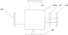
图1为本发明实施例VR光学系统结构示意图(折叠模组);1 is a schematic structural diagram of a VR optical system according to an embodiment of the present invention (folding module);
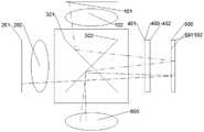
图2为本发明实施例VR光学系统结构示意图(光路合束模块与相位延迟反射模块);2 is a schematic structural diagram of a VR optical system according to an embodiment of the present invention (optical path beam combining module and phase delay reflection module);
图3为本发明实施例相位延迟反射模块结构示意图;3 is a schematic structural diagram of a phase delay reflection module according to an embodiment of the present invention;
图4为本发明实施例光路合束模块结构示意图;4 is a schematic structural diagram of an optical path beam combining module according to an embodiment of the present invention;
图5为本发明实施例第一光学图像放大结构示意图;5 is a schematic diagram of a first optical image magnification structure according to an embodiment of the present invention;
图6为本发明实施例第二光学图像放大结构示意图;6 is a schematic diagram of a second optical image magnification structure according to an embodiment of the present invention;
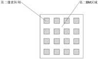
图7为本发明实施例第一BM区域与第二像素阵列重叠结构示意图;7 is a schematic diagram of the overlapping structure of the first BM region and the second pixel array according to an embodiment of the present invention;
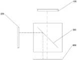
图8为本发明实施例折叠模组结构示意图(偏光分光膜)。FIG. 8 is a schematic structural diagram of a folding module according to an embodiment of the present invention (polarizing beam splitter film).
具体实施方式Detailed ways
下面将结合本发明实施例中的附图,对本发明实施例中的技术方案进行清楚、完整地描述,显然,所描述的实施例仅仅是本发明的一部分实施例,而不是全部的实施例。基于本发明中的实施例,本领域普通技术人员在没有作出创造性劳动前提下所获得的所有其他实施例,都属于本发明保护的范围。The technical solutions in the embodiments of the present invention will be clearly and completely described below with reference to the accompanying drawings in the embodiments of the present invention. Obviously, the described embodiments are only a part of the embodiments of the present invention, not all of the embodiments. Based on the embodiments of the present invention, all other embodiments obtained by those of ordinary skill in the art without creative efforts shall fall within the protection scope of the present invention.
需要说明,本发明实施例中所有方向性指示(诸如上、下、左、右、前、后……)仅用于解释在某一特定姿态(如附图所示)下各部件之间的相对位置关系、运动情况等,如果该特定姿态发生改变时,则该方向性指示也相应地随之改变。It should be noted that all directional indications (such as up, down, left, right, front, back, etc.) in the embodiments of the present invention are only used to explain the relationship between various components under a certain posture (as shown in the accompanying drawings). The relative positional relationship, the movement situation, etc., if the specific posture changes, the directional indication also changes accordingly.
在本发明中,除非另有明确的规定和限定,术语“连接”、“固定”等应做广义理解,例如,“固定”可以是固定连接,也可以是可拆卸连接,或成一体;可以是机械连接,也可以是电连接;可以是直接相连,也可以通过中间媒介间接相连,可以是两个元件内部的连通或两个元件的相互作用关系,除非另有明确的限定。对于本领域的普通技术人员而言,可以根据具体情况理解上述术语在本发明中的具体含义。In the present invention, unless otherwise expressly specified and limited, the terms "connected", "fixed" and the like should be understood in a broad sense, for example, "fixed" may be a fixed connection, a detachable connection, or an integrated; It can be a mechanical connection or an electrical connection; it can be a direct connection or an indirect connection through an intermediate medium, and it can be an internal communication between two elements or an interaction relationship between the two elements, unless otherwise explicitly defined. For those of ordinary skill in the art, the specific meanings of the above terms in the present invention can be understood according to specific situations.
另外,若本发明实施例中有涉及“第一”、“第二”等的描述,则该“第一”、“第二”等的描述仅用于描述目的,而不能理解为指示或暗示其相对重要性或者隐含指明所指示的技术特征的数量。由此,限定有“第一”、“第二”的特征可以明示或者隐含地包括至少一个该特征。另外,全文中出现的“和/或”的含义,包括三个并列的方案,以“A和/或B”为例,包括A方案、或B方案、或A和B同时满足的方案。另外,各个实施例之间的技术方案可以相互结合,但是必须是以本领域普通技术人员能够实现为基础,当技术方案的结合出现相互矛盾或无法实现时应当认为这种技术方案的结合不存在,也不在本发明要求的保护范围之内。In addition, if there are descriptions involving "first", "second", etc. in the embodiments of the present invention, the descriptions of "first", "second", etc. are only used for the purpose of description, and should not be construed as indicating or implying Its relative importance or implicitly indicates the number of technical features indicated. Thus, a feature delimited with "first", "second" may expressly or implicitly include at least one of that feature. In addition, the meaning of "and/or" in the whole text includes three parallel schemes. Taking "A and/or B" as an example, it includes scheme A, scheme B, or scheme satisfying both of A and B. In addition, the technical solutions between the various embodiments can be combined with each other, but must be based on the realization by those of ordinary skill in the art. When the combination of technical solutions is contradictory or cannot be realized, it should be considered that the combination of such technical solutions does not exist. , is not within the scope of protection required by the present invention.
如图1-图8所示,本发明提供的一种VR光学系统,包括光路折叠模组300、第一发光组件100和第二发光组件200,第一发光组件100和第二发光组件200设置于光路折叠模组300的周侧;第一发光组件100沿第一方向朝光路折叠模组300发射第一光学图像,第一光学图像沿第三方向从光路折叠模组300射向显像区域;第二发光组件200沿第二方向朝光路折叠模组300发射第二光学图像,第二光学图像沿第四方向从光路折叠模组300射向显像区域,第一光学图像与第二光学图像在显像区域进行重叠;As shown in FIG. 1-FIG. 8, a VR optical system provided by the present invention includes an optical
其中,第一方向与第二方向具有第一夹角,第一夹角大于且小于180°,第三方向与第四方向具有第二夹角,第二夹角大于或等于0°且小于180°;Wherein, the first direction and the second direction have a first angle, the first angle is greater than and less than 180°, the third direction and the fourth direction have a second angle, and the second angle is greater than or equal to 0° and less than 180° °;
光路折叠模组300被配置为可以通过调整第一夹角的角度以改变第二夹角的角度,从而调整所述第一光学图像与所述第二光学图像的重叠区域。The optical
需要说明的是:第一光学图像的BM区域为第一BM区域,第一光学图像的像素阵列为第一像素阵列,第二光学图像的BM区域为第二BM区域,第二光学图像的像素阵列为第二像素阵列。It should be noted that: the BM area of the first optical image is the first BM area, the pixel array of the first optical image is the first pixel array, the BM area of the second optical image is the second BM area, and the pixels of the second optical image are the first pixel array. The array is a second pixel array.
可以理解的是:由第一发光组件100沿第一方向朝光路折叠模组300发射第一光学图像,使第一光学图像沿第三方向从光路折叠模组300射向显像区域,由第二发光组件200沿第二方向朝光路折叠模组300发射第二光学图像,使第二光学图像沿第四方向从光路折叠模组300也射向显像区域,通过改变第一方向与第二方向的第一夹角(即改变第一发光组件100和第二发光组件200的位置)或光路折叠模组300的状态来控制第三方向与第四方向的第二夹角的角度大小,以使第一光学图像的第一BM区域与第二光学图像的第二像素阵列在显像区域进行重叠,通过将第二像素阵列的像素点叠加在第一BM区域,阻断第一BM区域的连续性,减小显示图像整体可视BM的面积,从而使纱窗效应得到明显改善,且当第二像素阵列处于与第一BM区域重叠时,在相同的显示区域内,像素点的数量得以提升,从而使显示图像的分辨率和亮度得以提升。因此,本发明提供的VR光学系统相比现有技术,能够减轻纱窗效应,提高显示画面的显示效果。It can be understood that: the first optical image is emitted from the first light-emitting
需要说明的是:调整第二夹角的角度大小实质是改变第三方向和第四方向的朝向,从而改变第一光学图像和第二光学图像在显像区域的投射位置,而由于第三方向和第四方向分别是第一光学图像和第二光学图像从光路折叠模组300中的射出方向,即能够影响第二夹角的角度大小的至少包括第一发光组件100的位置、第二发光组件200的位置以及光路折叠模组300本身结构,调整以上任意一个部件都可以改变第二夹角的角度大小。It should be noted that adjusting the angle size of the second included angle is essentially changing the orientation of the third and fourth directions, thereby changing the projection positions of the first optical image and the second optical image in the developing area. and the fourth direction are respectively the emission directions of the first optical image and the second optical image from the optical
能够理解的是:第一BM区域与第二像素阵列的重叠度需要根据实际需要进行调整。It can be understood that the degree of overlap between the first BM region and the second pixel array needs to be adjusted according to actual needs.
在本发明的另一种实施方式中,还可以通过改变光路折叠模组300的结构来改变第二夹角的角度,以使第一BM区域与第二像素阵列在显像区域进行重叠。In another embodiment of the present invention, the angle of the second included angle can also be changed by changing the structure of the optical
在本发明的一种实施方式中,所述第一发光组件100的发光偏振方向与所述第二发光组件200的发光偏振方向相同时,第一夹角为90°,光路折叠模组300包括光路合束模块300-a和相位延迟反射模块300-b,第二发光组件200、光路合束模块300-a以及相位延迟反射模块300-b沿第二方向依次间隔设置;In an embodiment of the present invention, when the light-emitting polarization direction of the first light-emitting
第一光学图像射向光路折叠模组300后,第一光学图像先经过光路合束模块300-a,再由光路合束模块300-a射向相位延迟反射模块300-b,经相位延迟反射模300-b块改变其偏振方向后再射向光路合束模块300-a,最后由光路合束模块300-a沿第三方向射向显像区域;After the first optical image is directed to the optical
第二光学图像射向光路折叠模组300后,第二光学图像先经过光路合束模块300-a,再由光路合束模块300-a射向相位延迟反射模块300-b,经相位延迟反射模300-b改变其偏振方向后再射向光路合束模块300-a,最后由光路合束模块300-a沿第四方向射向显像区域;After the second optical image is directed to the optical
其中,第一光学图像改变后的偏振方向与其原偏振方向垂直,第二光学图像改变后的偏振方向与其原偏振方向垂直。Wherein, the changed polarization direction of the first optical image is perpendicular to its original polarization direction, and the changed polarization direction of the second optical image is perpendicular to its original polarization direction.
光路合束模块300-a包括彼此垂直且交叉设置的反射型偏振膜302和半透半反射膜301,半透半反射膜301沿第一夹角的角平分线设置,反射型偏振膜302的透射轴与第一光学图像和第二光学图像的偏振方向平行。The optical path beam combining module 300-a includes a reflective
需要说明的是:第一发光组件100的发光偏振方向为第一发光组件发出第一光学图像时第一光学图像的偏振方向;第二发光组件200的发光偏振方向为第二发光组件发出第二发光图像时第二光学图像的偏振方向。It should be noted that the light-emitting polarization direction of the first light-emitting
可以理解的是:第一夹角为90°时,第一方向与第二方向相互垂直;而半透半反射膜301沿第一夹角的角平分线设置,反射型偏振膜302与半透半反射膜301垂直交叉设置,沿第一方向射向光路合束模块300-a的第一光学图像由半透半反射膜301反射射向相位延迟反射模块300-b,经相位延迟反射模块300-b改变偏振方向后反射回光路合束模块300-a,再由反射型偏振膜302反射沿第三方向射出光路合束模块300-a;沿第二方向射向光路合束模块300-a的第二光学图像透射过反射型偏振膜302射向相位延迟反射模块300-b,经相位延迟反射模块300-b改变偏振方向后反射回光路合束模块300-a,再由反射型偏振膜302反射沿第四方向射出光路合束模块300-a。It can be understood that: when the first angle is 90°, the first direction and the second direction are perpendicular to each other; and the semi-transmissive and
需要说明的是:由于第一光学图像的原偏振方向、第二光学图像的原偏振方向均与反射型偏振膜302的透射轴平行,则第一光学图像和第二光学图像均能透射过反射型偏振膜302射向相位延迟反射模块300-b,而经过相位延迟反射模块300-b改变后的偏振方向与原偏振方向垂直,即偏振方向发射改变的第一光学图像和第二光学图像不能透射过反射型偏振膜302,只能在反射型偏振膜302上发生反射,即改变偏振方向后的第一光学图像和第二光学图像均在反射型偏振膜302上发生反射分别沿第三方向和第四方向射出。It should be noted that since the original polarization direction of the first optical image and the original polarization direction of the second optical image are both parallel to the transmission axis of the reflective
作为上述实施例的可选实施方式,半透半反射膜301的透光率和反光率分别为50%,能够理解的是,本发明中的VR光学系统可以根据实际使用情况选择其他数值透光率和反光率的半透半反射膜301。As an optional implementation of the above-mentioned embodiment, the light transmittance and light reflectance of the semi-transmissive and
作为上述实施方式的可选地实施方式,半透半反射膜301在第一方向的正投影面积与反射型偏振膜302在第一方向的正投影面积相等;As an optional implementation of the above embodiment, the orthographic projection area of the
半透半反射膜301在第二方向的正投影面积与反射型偏振膜302在第二方向的正投影面积相等。The orthographic projection area of the
可以理解的是:半透半反射膜301在第一方向和第二方向的正投影面积与反射型偏振膜302在第一方向和第二方向的正投影面积相等,可以保证第一光学图像和第二光学图像在经过光路合束模块300-a的过程中的完整性,即保证第一光学图像和第二光学图像在显像区域显像时不会存在缺失。It can be understood that the orthographic projection area of the
作为上述实施例的可选地实施方式,半透半反射膜301、反射型偏振膜302在第一方向的正投影面积均与第一发光组件100的发光面积相等;能够理解的是前述三者面积相等,能够保证光路合束模块300-a能够完整的接受第一光学图像,保证第一光学图像的完整性。As an optional implementation of the above-mentioned embodiment, the orthographic projection area of the semi-transmissive and
作为上述实施例的可选实施方式,半透半反射膜301、反射型偏振膜302在第二方向的正投影面积均与第二发光组件200的发光面积相等;能够理解的是,前述三者面积相等,能够保证光路合束模块300-a能够完整的接受第二光学图像,保证第二光学图像的完整性。As an optional implementation of the above-mentioned embodiment, the orthographic projection area of the semi-transmissive and
作为上述实施例的可选实施发方式,相位延迟反射模块300-b包括相位延迟器400以及与相位延迟器400间隔设置的第三透镜500,相位延迟器400设置于第三透镜500与光路合束模块300-a之间;第三透镜500远离相位延迟器400的光学面设置有反射膜,用于将由相位延迟器400射向第三透镜500的光线反射回相位延迟器400。As an optional implementation manner of the above embodiment, the phase delay reflection module 300-b includes a
具体的,第三透镜500具有第一光学面501和第二光学面502,第一光学面501和第二光学面502均与相位延迟器400的光学面平行,其中,第三透镜500靠近相位延迟器400的光学面为第一光学面501,远离相位延迟器400的光学面为第二光学面502,第二光学面502设置有反射膜,在第二光学面502设置有反射膜,第三透镜500用于将射向通过相位延迟器400的光学图像进行放大,并反射回相位延迟器400。Specifically, the
作为上述实施例的另一种可选实施方式,相位延迟器400包括设置于光路合束模块300-a一侧的相位延迟器400以及贴合于相位延迟器400远离光路合束模块300-a的光学平面的反射膜。As another optional implementation of the above embodiment, the
具体的,相位延迟器400具有平行的第三光学面401和第四光学面402,第三光学面401靠近光路合束模块300-a,第四光学面402远离光路合束模块300-a,在第四光学面402设置有反射膜,用于将经过相位延迟器400改变的光学图像反射回光路合束模块300-a。Specifically, the
作为上述实施方式的替代实施方式,设置于第二光学面502的反射膜或设置于第四光学面402的反射膜替换为反射镀层。As an alternative to the above-mentioned embodiment, the reflective film provided on the second optical surface 502 or the reflective film provided on the fourth optical surface 402 is replaced with a reflective coating.
在本发明的一种实施方式中,第一光学图像的偏振方向与第二光学图像的偏振方向垂直时,第一夹角大于0°且小于或等于90°,光路折叠模组300为沿第一夹角的角平分线设置的偏光分光膜303;In an embodiment of the present invention, when the polarization direction of the first optical image is perpendicular to the polarization direction of the second optical image, the first included angle is greater than 0° and less than or equal to 90°, and the optical
偏光分光膜303的透射轴与第一光学图像的偏振方向平行;或The transmission axis of the polarizing
偏光分光膜303的透射轴与第二光学图像的偏振方向平行。The transmission axis of the polarizing
可以理解的是:偏振方向与偏光分光膜303的透射轴平行的光学图像直接穿过偏光分光膜303,偏振方向与偏光分光膜303的透射轴垂直的光学图像在偏光分光膜303上发生反射。It can be understood that: the optical image whose polarization direction is parallel to the transmission axis of the polarizing
若第一光学图像的偏振方向与偏光分光膜303的透射轴平行,则第一光学图像直接穿过偏光分光膜303并沿第三方向射出光路折叠模组300,此时,第一方向与第三方向同向。If the polarization direction of the first optical image is parallel to the transmission axis of the polarizing
若第二光学图像的偏振方向与偏光分光膜303的透射轴平行,则第二光学图像直接穿过偏光分光膜303并沿第四方向射出光路折叠模组300,此时,第二方向与第三方向同向。If the polarization direction of the second optical image is parallel to the transmission axis of the polarizing
在本发明的一种实施方式中,第一发光组件100包括沿第一方向依次设置的第一发光面101以及平行于第一发光面101的第一透镜102;In an embodiment of the present invention, the first light-emitting
第二发光组件200包括沿第二方向依次设置的第二发光面201以及平行于第二发光面201的第二透镜202。The second
可以理解的是:设置第一透镜102和第二透镜202用于对第一光学图像和第二光学图像进行放大,且第一发光面101和第二发光面201可以是直面显也可以是曲面。It can be understood that: the
在本发明的一种实施方式中,光路折叠模组300与显像区域之间还设置有第四透镜600,第一光学图像和第二光学图像透射过第四透镜600到达显像区域。In an embodiment of the present invention, a
具体的,第四透镜600与显像区域形成的显像平面平行,用于对射向显像区域的第一光学图像和第二光学图像进行再次放大。Specifically, the
在本发明的一种实施方式中,VR光学系统包括第一发光平面、与第一发光平面平行的第一透镜102、与第一发光平面垂直的第二发光平面、与第二发光平面平行的第二透镜202,第一发光平面沿第一方向发射第一光学图像,第二发光平面沿第二方向发射第二光学图像,其中,第一光学图像和第二光学图像的偏振方向相同;VR光学系统还包括光路合束模块300-a、相位延迟器400和第三透镜500,其中第一发光平面和第一透镜102设置于光路合束模块300-a的一侧,第二发光平面和第二透镜202设置于光路合束模块300-a的另一侧,第二发光平面、第二透镜202、光路合束模块300-a、相位延迟器400以及第三透镜500沿第二方向依次间隔设置,第三透镜500具有相互平行的第一光学面501和第二光学面502,第一光学面501靠近相位延迟器400,第二光学面502远离相位延迟器400,第二光学面502设置有用于反射光学图像的反射膜;光路合束模块300-a包括彼此垂直且交叉设置的反射型偏振膜302和半透半反射膜301,半透半反射膜301沿第一方向和第二方向夹角的角平分线设置,反射型偏振膜302的透射轴与第一光学图像和第二光学图像的偏振方向平行,光路合束模块300-a与显像区域之间还设置有第四透镜600。In one embodiment of the present invention, the VR optical system includes a first light-emitting plane, a first lens 102 parallel to the first light-emitting plane, a second light-emitting plane perpendicular to the first light-emitting plane, and a second light-emitting plane parallel to the second light-emitting plane The second lens 202, the first light-emitting plane emits a first optical image along a first direction, and the second light-emitting plane emits a second optical image along a second direction, wherein the polarization directions of the first optical image and the second optical image are the same; VR The optical system also includes an optical path beam combining module 300-a, a phase retarder 400 and a third lens 500, wherein the first light emitting plane and the first lens 102 are arranged on one side of the optical path beam combining module 300-a, and the second light emitting plane and The second lens 202 is disposed on the other side of the optical path beam combining module 300-a, and the second light emitting plane, the second lens 202, the optical path beam combining module 300-a, the phase retarder 400 and the third lens 500 are in sequence along the second direction Spaced apart, the third lens 500 has a first optical surface 501 and a second optical surface 502 that are parallel to each other, the first optical surface 501 is close to the retarder 400 , the second optical surface 502 is far away from the retarder 400 , and the second optical surface 502 A reflective film for reflecting optical images is provided; the optical path beam combining module 300-a includes a reflective polarizing film 302 and a semi-transmissive and semi-reflective film 301 that are perpendicular to each other and crossed, and the semi-transparent and semi-reflective film 301 is along the first direction and the second The angle bisector of the included angle is set, the transmission axis of the reflective polarizing film 302 is parallel to the polarization directions of the first optical image and the second optical image, and a fourth optical path beam combining module 300-a and the imaging area are also provided.
第一光学图像射向光路合束模块300-a后由光路合束模块300-a射向相位延迟器400,第一光学图像经相位延迟器400改变其偏振方向后射向第三透镜500,再由第二光学面502上的反射膜反射回光路合束器,最后第一光学图像沿第三方向从光路合束模块300-a射向显像区域;The first optical image is sent to the optical path beam combining module 300-a and then sent to the
第二光学图像射向光路合束模块300-a后由光路合束模块300-a射向相位延迟器400,第二光学图像经相位延迟器400改变其偏振方向后射向第三透镜500,再由第二光学面502上的反射膜反射回光路合束器,最后第二光学图像沿第四方向从光路合束模块300-a射向显像区域。The second optical image is sent to the optical path beam combining module 300-a and then sent to the
本实施方式在光学总长不变的情况下采用折叠光路,增加第一光学图像和第二光学图像的光程长,将第一光学图像和第二光学图像通过透镜进行三次放大,极大地提高了第一光学图像和第二光学图像的视场角。This embodiment adopts a folded optical path under the condition that the total optical length remains unchanged, increases the optical path length of the first optical image and the second optical image, and magnifies the first optical image and the second optical image three times through the lens, which greatly improves the The field of view of the first optical image and the second optical image.
作为上述实施方式的实际应用,第一透镜102和第二透镜202分别采用不同光焦度的透镜,以形成两个不同FOV的光学图像进行传输,调整第二夹角的大小使第一光学图和第二光学图像在显像区域进行重叠,并使最终显像图像呈现中心区域为小FOV高PPD画面,外部区域为大FOV低PPD画面,确保人眼主视区具有较高的清晰度。As a practical application of the above-mentioned embodiment, the
在本发明的一种可选地实施方式中,第一透镜102、第二透镜202、第三透镜500和第四透镜600均采用双面凸透镜,对第一光学图像和第二光学图像进行放大。In an optional embodiment of the present invention, the
本发明提供的VR光学系统可应用于多种VR显示设备,包括但不限于头戴式VR眼镜、VR显像屏等,由于该VR显示设备采用了上述实施例的部分或者全部技术方案,因此至少具有上述实施例的技术方案所带来的所有有益效果,在此不再一一赘述。The VR optical system provided by the present invention can be applied to a variety of VR display devices, including but not limited to head-mounted VR glasses, VR display screens, etc. At least all the beneficial effects brought by the technical solutions of the above-mentioned embodiments are provided, which will not be repeated here.
以上所述仅为本发明的可选实施例,并非因此限制本发明的专利范围,凡是在本发明的发明构思下,利用本发明说明书及附图内容所作的等效结构变换,或直接/间接运用在其他相关的技术领域均包括在本发明的专利保护范围内。The above descriptions are only optional embodiments of the present invention, and are not intended to limit the scope of the present invention. Under the inventive concept of the present invention, any equivalent structural transformations made by using the contents of the description and drawings of the present invention, or direct/indirect Applications in other related technical fields are included in the scope of patent protection of the present invention.
Claims (10)
Priority Applications (3)
| Application Number | Priority Date | Filing Date | Title |
|---|---|---|---|
| CN202210050795.1ACN114371557B (en) | 2022-01-17 | 2022-01-17 | VR optical system |
| EP23739850.8AEP4468059A1 (en) | 2022-01-17 | 2023-01-04 | Vr optical system |
| PCT/CN2023/070255WO2023134506A1 (en) | 2022-01-17 | 2023-01-04 | Vr optical system |
Applications Claiming Priority (1)
| Application Number | Priority Date | Filing Date | Title |
|---|---|---|---|
| CN202210050795.1ACN114371557B (en) | 2022-01-17 | 2022-01-17 | VR optical system |
Publications (2)
| Publication Number | Publication Date |
|---|---|
| CN114371557Atrue CN114371557A (en) | 2022-04-19 |
| CN114371557B CN114371557B (en) | 2024-02-09 |
Family
ID=81144676
Family Applications (1)
| Application Number | Title | Priority Date | Filing Date |
|---|---|---|---|
| CN202210050795.1AActiveCN114371557B (en) | 2022-01-17 | 2022-01-17 | VR optical system |
Country Status (3)
| Country | Link |
|---|---|
| EP (1) | EP4468059A1 (en) |
| CN (1) | CN114371557B (en) |
| WO (1) | WO2023134506A1 (en) |
Cited By (3)
| Publication number | Priority date | Publication date | Assignee | Title |
|---|---|---|---|---|
| CN115857216A (en)* | 2022-12-15 | 2023-03-28 | 维沃移动通信有限公司 | Methods, devices and systems are shown |
| CN115967850A (en)* | 2022-12-28 | 2023-04-14 | 歌尔科技有限公司 | Multifunctional camera module and VR equipment |
| WO2023134506A1 (en)* | 2022-01-17 | 2023-07-20 | 惠州Tcl移动通信有限公司 | Vr optical system |
Citations (15)
| Publication number | Priority date | Publication date | Assignee | Title |
|---|---|---|---|---|
| CN205562977U (en)* | 2016-03-21 | 2016-09-07 | 深圳多哚新技术有限责任公司 | Short distance optical enlargement module, glasses, helmet and VR system |
| CN106444058A (en)* | 2016-09-28 | 2017-02-22 | 惠州Tcl移动通信有限公司 | Virtual reality display helmet-mounted device and optical component |
| CN107561704A (en)* | 2016-06-30 | 2018-01-09 | 三星显示有限公司 | Head-mounted display apparatus and the method for driving the head-mounted display apparatus |
| CN107589546A (en)* | 2017-10-23 | 2018-01-16 | 北京小米移动软件有限公司 | Optical system and augmented reality glasses |
| US20180024373A1 (en)* | 2016-07-25 | 2018-01-25 | Disney Enterprises, Inc. | Retroreflector display system for generating floating image effects |
| CN108572453A (en)* | 2018-03-20 | 2018-09-25 | 友达光电股份有限公司 | Display device |
| CN209167797U (en)* | 2018-12-11 | 2019-07-26 | 中强光电股份有限公司 | Imaging system and projection device |
| CN209496201U (en)* | 2019-03-28 | 2019-10-15 | 歌尔科技有限公司 | VR optical system and VR display equipment |
| CN110603477A (en)* | 2018-02-12 | 2019-12-20 | 优奈柯恩(北京)科技有限公司 | Wearable AR system and AR display device |
| CN111367085A (en)* | 2020-04-30 | 2020-07-03 | 宁波鸿蚁光电科技有限公司 | An optical display system and AR device with a folded optical path |
| US10739586B1 (en)* | 2017-08-07 | 2020-08-11 | Facebook Technologies, Llc | Reflective polarizer for augmented reality and virtual reality display |
| WO2020258541A1 (en)* | 2019-06-25 | 2020-12-30 | 武汉华星光电半导体显示技术有限公司 | Display panel and display device |
| CN113253457A (en)* | 2021-05-11 | 2021-08-13 | 京东方科技集团股份有限公司 | Display device and display control method thereof |
| CN113489960A (en)* | 2021-06-30 | 2021-10-08 | 青岛海信激光显示股份有限公司 | Projection display device, method and system |
| CN113721415A (en)* | 2021-08-30 | 2021-11-30 | 歌尔光学科技有限公司 | Projection light machine |
Family Cites Families (4)
| Publication number | Priority date | Publication date | Assignee | Title |
|---|---|---|---|---|
| JPH11237584A (en)* | 1997-12-19 | 1999-08-31 | Sharp Corp | Image display device, head-mounted display using the image display device, and video communication device |
| CN209542962U (en)* | 2018-12-12 | 2019-10-25 | 深圳创维新世界科技有限公司 | A kind of VR glasses |
| CN110208948B (en)* | 2019-06-03 | 2020-11-24 | 歌尔光学科技有限公司 | Optical system and virtual reality device having the same |
| CN114371557B (en)* | 2022-01-17 | 2024-02-09 | 惠州Tcl移动通信有限公司 | VR optical system |
- 2022
- 2022-01-17CNCN202210050795.1Apatent/CN114371557B/enactiveActive
- 2023
- 2023-01-04WOPCT/CN2023/070255patent/WO2023134506A1/ennot_activeCeased
- 2023-01-04EPEP23739850.8Apatent/EP4468059A1/enactivePending
Patent Citations (15)
| Publication number | Priority date | Publication date | Assignee | Title |
|---|---|---|---|---|
| CN205562977U (en)* | 2016-03-21 | 2016-09-07 | 深圳多哚新技术有限责任公司 | Short distance optical enlargement module, glasses, helmet and VR system |
| CN107561704A (en)* | 2016-06-30 | 2018-01-09 | 三星显示有限公司 | Head-mounted display apparatus and the method for driving the head-mounted display apparatus |
| US20180024373A1 (en)* | 2016-07-25 | 2018-01-25 | Disney Enterprises, Inc. | Retroreflector display system for generating floating image effects |
| CN106444058A (en)* | 2016-09-28 | 2017-02-22 | 惠州Tcl移动通信有限公司 | Virtual reality display helmet-mounted device and optical component |
| US10739586B1 (en)* | 2017-08-07 | 2020-08-11 | Facebook Technologies, Llc | Reflective polarizer for augmented reality and virtual reality display |
| CN107589546A (en)* | 2017-10-23 | 2018-01-16 | 北京小米移动软件有限公司 | Optical system and augmented reality glasses |
| CN110603477A (en)* | 2018-02-12 | 2019-12-20 | 优奈柯恩(北京)科技有限公司 | Wearable AR system and AR display device |
| CN108572453A (en)* | 2018-03-20 | 2018-09-25 | 友达光电股份有限公司 | Display device |
| CN209167797U (en)* | 2018-12-11 | 2019-07-26 | 中强光电股份有限公司 | Imaging system and projection device |
| CN209496201U (en)* | 2019-03-28 | 2019-10-15 | 歌尔科技有限公司 | VR optical system and VR display equipment |
| WO2020258541A1 (en)* | 2019-06-25 | 2020-12-30 | 武汉华星光电半导体显示技术有限公司 | Display panel and display device |
| CN111367085A (en)* | 2020-04-30 | 2020-07-03 | 宁波鸿蚁光电科技有限公司 | An optical display system and AR device with a folded optical path |
| CN113253457A (en)* | 2021-05-11 | 2021-08-13 | 京东方科技集团股份有限公司 | Display device and display control method thereof |
| CN113489960A (en)* | 2021-06-30 | 2021-10-08 | 青岛海信激光显示股份有限公司 | Projection display device, method and system |
| CN113721415A (en)* | 2021-08-30 | 2021-11-30 | 歌尔光学科技有限公司 | Projection light machine |
Cited By (3)
| Publication number | Priority date | Publication date | Assignee | Title |
|---|---|---|---|---|
| WO2023134506A1 (en)* | 2022-01-17 | 2023-07-20 | 惠州Tcl移动通信有限公司 | Vr optical system |
| CN115857216A (en)* | 2022-12-15 | 2023-03-28 | 维沃移动通信有限公司 | Methods, devices and systems are shown |
| CN115967850A (en)* | 2022-12-28 | 2023-04-14 | 歌尔科技有限公司 | Multifunctional camera module and VR equipment |
Also Published As
| Publication number | Publication date |
|---|---|
| WO2023134506A1 (en) | 2023-07-20 |
| CN114371557B (en) | 2024-02-09 |
| EP4468059A1 (en) | 2024-11-27 |
Similar Documents
| Publication | Publication Date | Title |
|---|---|---|
| JP6926360B2 (en) | Compact head-mounted display system that displays a uniform image | |
| CN107329273B (en) | Near-to-eye display device | |
| US11287649B2 (en) | Display device and display method | |
| JP5973098B1 (en) | Optical module for near-eye display | |
| CN114371557A (en) | VR optical system | |
| US7242524B2 (en) | Optical system for forming a real image in space | |
| KR20010073072A (en) | Head-mounted display | |
| US20240210716A1 (en) | Optical lens assembly, optical system and head-mounted display device | |
| CN108983423A (en) | A kind of Binocular displays system and vehicle-mounted head-up-display system | |
| US20210191116A1 (en) | Head-up display and vehicle | |
| WO2017128183A1 (en) | Short-distance optical amplification module, amplification method and amplification system | |
| CN104536139B (en) | A kind of tapered planar wave guide optics of prism-coupled | |
| CN111999898A (en) | Optical display system and display device | |
| US11644673B2 (en) | Near-eye optical system | |
| CN209858857U (en) | Optical system and virtual reality equipment with same | |
| US20240061240A1 (en) | Air floating video display apparatus and light source | |
| CN114911063A (en) | Focal plane imaging system applied to virtual reality display | |
| CN114296226A (en) | Optical module, optical system and head-mounted display equipment | |
| JP7664288B2 (en) | Three-dimensional display device | |
| CN116047649A (en) | Geometric optical waveguide coupling device and near-to-eye display equipment | |
| JP3524569B2 (en) | Visual display device | |
| CN117647895A (en) | Optical module and near-to-eye display device | |
| CN116149065B (en) | Optical module and wearable equipment | |
| CN216622845U (en) | Augmented reality optical system and binocular optical system | |
| CN218122372U (en) | Optical display module and near-to-eye display equipment |
Legal Events
| Date | Code | Title | Description |
|---|---|---|---|
| PB01 | Publication | ||
| PB01 | Publication | ||
| SE01 | Entry into force of request for substantive examination | ||
| SE01 | Entry into force of request for substantive examination | ||
| GR01 | Patent grant | ||
| GR01 | Patent grant |