CN114371052A - A liquid-based cell sample preparation device - Google Patents
A liquid-based cell sample preparation deviceDownload PDFInfo
- Publication number
- CN114371052A CN114371052ACN202111482993.7ACN202111482993ACN114371052ACN 114371052 ACN114371052 ACN 114371052ACN 202111482993 ACN202111482993 ACN 202111482993ACN 114371052 ACN114371052 ACN 114371052A
- Authority
- CN
- China
- Prior art keywords
- liquid
- needle
- sample
- bottle
- pump
- Prior art date
- Legal status (The legal status is an assumption and is not a legal conclusion. Google has not performed a legal analysis and makes no representation as to the accuracy of the status listed.)
- Pending
Links
- 239000007788liquidSubstances0.000titleclaimsabstractdescription209
- 238000002360preparation methodMethods0.000titleclaimsabstractdescription49
- 230000007246mechanismEffects0.000claimsabstractdescription166
- 238000004140cleaningMethods0.000claimsabstractdescription119
- 238000004043dyeingMethods0.000claimsabstractdescription50
- 239000002699waste materialSubstances0.000claimsabstractdescription37
- 238000000926separation methodMethods0.000claimsabstractdescription32
- 230000004069differentiationEffects0.000claimsdescription41
- XLYOFNOQVPJJNP-UHFFFAOYSA-NwaterSubstancesOXLYOFNOQVPJJNP-UHFFFAOYSA-N0.000claimsdescription31
- 238000005406washingMethods0.000claimsdescription13
- 230000002380cytological effectEffects0.000claims9
- 230000005611electricityEffects0.000claims1
- 239000012535impuritySubstances0.000abstractdescription12
- 238000003745diagnosisMethods0.000abstractdescription10
- 238000012864cross contaminationMethods0.000abstractdescription5
- 238000000746purificationMethods0.000abstractdescription4
- 238000012423maintenanceMethods0.000abstractdescription3
- 239000000463materialSubstances0.000abstractdescription3
- 238000010586diagramMethods0.000description14
- 239000000243solutionSubstances0.000description12
- 238000004519manufacturing processMethods0.000description10
- 238000003860storageMethods0.000description10
- 230000009286beneficial effectEffects0.000description8
- 238000000034methodMethods0.000description8
- 238000010186stainingMethods0.000description8
- 230000008569processEffects0.000description6
- 239000011521glassSubstances0.000description5
- 238000005070samplingMethods0.000description5
- 230000005540biological transmissionEffects0.000description4
- 230000005484gravityEffects0.000description4
- 239000012192staining solutionSubstances0.000description3
- 239000002351wastewaterSubstances0.000description3
- WZUVPPKBWHMQCE-UHFFFAOYSA-NHaematoxylinChemical compoundC12=CC(O)=C(O)C=C2CC2(O)C1C1=CC=C(O)C(O)=C1OC2WZUVPPKBWHMQCE-UHFFFAOYSA-N0.000description2
- 230000004308accommodationEffects0.000description2
- 238000005119centrifugationMethods0.000description2
- 230000008878couplingEffects0.000description2
- 238000010168coupling processMethods0.000description2
- 238000005859coupling reactionMethods0.000description2
- 230000001360synchronised effectEffects0.000description2
- 206010011409Cross infectionDiseases0.000description1
- 206010029803Nosocomial infectionDiseases0.000description1
- 239000004809TeflonSubstances0.000description1
- 229920006362Teflon®Polymers0.000description1
- 230000009471actionEffects0.000description1
- 230000000712assemblyEffects0.000description1
- 238000000429assemblyMethods0.000description1
- 239000008280bloodSubstances0.000description1
- 210000004369bloodAnatomy0.000description1
- 238000006243chemical reactionMethods0.000description1
- 239000012141concentrateSubstances0.000description1
- 239000013078crystalSubstances0.000description1
- 230000007812deficiencyEffects0.000description1
- 238000005516engineering processMethods0.000description1
- 230000002452interceptive effectEffects0.000description1
- 230000003902lesionEffects0.000description1
- 210000003097mucusAnatomy0.000description1
- 238000010827pathological analysisMethods0.000description1
- 239000003761preservation solutionSubstances0.000description1
- 238000004904shorteningMethods0.000description1
- 230000009466transformationEffects0.000description1
Images


Classifications
- G—PHYSICS
- G01—MEASURING; TESTING
- G01N—INVESTIGATING OR ANALYSING MATERIALS BY DETERMINING THEIR CHEMICAL OR PHYSICAL PROPERTIES
- G01N1/00—Sampling; Preparing specimens for investigation
- G01N1/28—Preparing specimens for investigation including physical details of (bio-)chemical methods covered elsewhere, e.g. G01N33/50, C12Q
- G01N1/2813—Producing thin layers of samples on a substrate, e.g. smearing, spinning-on
- G—PHYSICS
- G01—MEASURING; TESTING
- G01N—INVESTIGATING OR ANALYSING MATERIALS BY DETERMINING THEIR CHEMICAL OR PHYSICAL PROPERTIES
- G01N1/00—Sampling; Preparing specimens for investigation
- G01N1/28—Preparing specimens for investigation including physical details of (bio-)chemical methods covered elsewhere, e.g. G01N33/50, C12Q
- G01N1/30—Staining; Impregnating ; Fixation; Dehydration; Multistep processes for preparing samples of tissue, cell or nucleic acid material and the like for analysis
- G—PHYSICS
- G01—MEASURING; TESTING
- G01N—INVESTIGATING OR ANALYSING MATERIALS BY DETERMINING THEIR CHEMICAL OR PHYSICAL PROPERTIES
- G01N1/00—Sampling; Preparing specimens for investigation
- G01N1/28—Preparing specimens for investigation including physical details of (bio-)chemical methods covered elsewhere, e.g. G01N33/50, C12Q
- G01N1/34—Purifying; Cleaning
- G—PHYSICS
- G01—MEASURING; TESTING
- G01N—INVESTIGATING OR ANALYSING MATERIALS BY DETERMINING THEIR CHEMICAL OR PHYSICAL PROPERTIES
- G01N1/00—Sampling; Preparing specimens for investigation
- G01N1/28—Preparing specimens for investigation including physical details of (bio-)chemical methods covered elsewhere, e.g. G01N33/50, C12Q
- G01N1/40—Concentrating samples
- G—PHYSICS
- G01—MEASURING; TESTING
- G01N—INVESTIGATING OR ANALYSING MATERIALS BY DETERMINING THEIR CHEMICAL OR PHYSICAL PROPERTIES
- G01N1/00—Sampling; Preparing specimens for investigation
- G01N1/28—Preparing specimens for investigation including physical details of (bio-)chemical methods covered elsewhere, e.g. G01N33/50, C12Q
- G01N1/2813—Producing thin layers of samples on a substrate, e.g. smearing, spinning-on
- G01N2001/2846—Cytocentrifuge method
Landscapes
- Life Sciences & Earth Sciences (AREA)
- Health & Medical Sciences (AREA)
- General Health & Medical Sciences (AREA)
- Chemical & Material Sciences (AREA)
- Analytical Chemistry (AREA)
- Biochemistry (AREA)
- Physics & Mathematics (AREA)
- General Physics & Mathematics (AREA)
- Immunology (AREA)
- Pathology (AREA)
- Engineering & Computer Science (AREA)
- Biomedical Technology (AREA)
- Molecular Biology (AREA)
- Investigating Or Analysing Biological Materials (AREA)
Abstract
Description
Translated fromChinese技术领域technical field
本发明涉及液基细胞样本制作技术领域,尤其涉及一种液基细胞样本制作装置。The invention relates to the technical field of liquid-based cell sample preparation, in particular to a liquid-based cell sample preparation device.
背景技术Background technique
液基细胞学是病理诊断中一种重要的癌前病变诊断方法学之一,是将所采集的脱落细胞样本放入液基细胞保存液中,以去除血液、粘液等影响诊断的干扰成分,达到提高诊断效率的目的。液基细胞学的样本制备与诊断过程通常包括:样本前处理、制片、染色、透明、显微镜下诊断判读等步骤。传统的制片染色等步骤是由人工手动进行,这样会需要制片者长时间工作,并且因为染色过程无法实现标准化控制,易造成人为因素的干扰,导致每批的染色质量不一致,影响镜下诊断判读。Liquid-based cytology is one of the most important diagnostic methodologies for precancerous lesions in pathological diagnosis. The collected exfoliated cell samples are placed in a liquid-based cell preservation solution to remove blood, mucus and other interfering components that affect the diagnosis. To achieve the purpose of improving the diagnostic efficiency. The sample preparation and diagnosis process of liquid-based cytology usually includes steps such as sample pretreatment, preparation, staining, transparency, and diagnostic interpretation under the microscope. The traditional production and dyeing steps are carried out manually, which will require the filmmaker to work for a long time, and because the dyeing process cannot be standardized and controlled, it is easy to cause the interference of human factors, resulting in inconsistent dyeing quality of each batch, affecting the microscope. Diagnostic interpretation.
现有技术中申请号为CN201610518467.4的中国发明专利中记载了一种全自动液基薄层细胞制片染色装置,但仍存在以下不足之处:In the prior art, the Chinese invention patent with the application number of CN201610518467.4 has recorded a fully automatic liquid-based thin-layer cell preparation dyeing device, but still has the following deficiencies:
(1)无细胞分离纯化功能,使得样本中的干扰诊断的杂质一并被混入载玻片中,从而影响诊断的准确性;(1) Cell-free separation and purification function, so that impurities in the sample that interfere with diagnosis are mixed into the slide, thereby affecting the accuracy of diagnosis;
(2)移液机构设置在放样区圆心处,存在移液过程中沿移液针轨迹易造成样本滴落而产生交叉污染的可能;(2) The pipetting mechanism is set at the center of the stakeout area, and there is a possibility that the sample will drip along the trajectory of the pipetting needle during the pipetting process, resulting in cross-contamination;
(3)仅用一个移液机构完成取样、加液、清洗以及吸取废液等操作,容易出现交叉污染的现象,影响后期诊断。(3) Only one pipetting mechanism is used to complete operations such as sampling, adding liquid, cleaning and sucking waste liquid, which is prone to cross-contamination and affects later diagnosis.
在同类产品中虽然还有一些产品具有样本的普通离心功能,在一定程度上可以浓缩样本增加细胞量,但均不具备纯化分离细胞功能,仍然存在杂质等非诊断成分的干扰而影响诊断。Although there are some products of the same kind that have the common centrifugation function of the sample, which can concentrate the sample to increase the cell volume to a certain extent, they do not have the function of purifying and separating cells, and there are still interference from non-diagnostic components such as impurities that affect the diagnosis.
并且细胞学染色液的中苏木素、EA50或EAOG等染色液极易产生结晶,如果不及时清洗会造成堵针或堵管,造成设备故障或使染色失败,或者是结晶贴附于载玻片上,造成显微镜下观察时载玻片背景大量杂质,影响诊断。传统的细胞制片染色装置均需人工进行清洗处理,处理过程也非常不便。In addition, the hematoxylin, EA50 or EAOG and other staining solutions in the cytology staining solution are prone to crystallize. If they are not cleaned in time, they will cause plugging of needles or tubes, causing equipment failure or staining failure, or crystals sticking to the glass slide. Causes a lot of impurities in the background of the slide glass when observed under the microscope, which affects the diagnosis. The traditional cell preparation and staining devices all need to be cleaned manually, and the processing process is also very inconvenient.
发明内容SUMMARY OF THE INVENTION
(一)要解决的技术问题(1) Technical problems to be solved
为了解决现有技术的上述问题,本发明提供一种液基细胞样本制作装置,能够实现细胞分离纯化、制片、染色、透明以及针、管自动化清洁维护,提升诊断的准确性,并且防止样本之间发生交叉污染,节省人力物力,缩短了工作时间。In order to solve the above problems of the prior art, the present invention provides a liquid-based cell sample preparation device, which can realize cell separation and purification, preparation, staining, transparency, and automatic cleaning and maintenance of needles and tubes, improve the accuracy of diagnosis, and prevent samples Cross-contamination occurs between them, saving manpower and material resources and shortening working hours.
(二)技术方案(2) Technical solutions
为了达到上述目的,本发明采用的主要技术方案包括:In order to achieve the above-mentioned purpose, the main technical scheme adopted in the present invention includes:
一种液基细胞样本制作装置,包括机台、分离机构、制片机构、样本处理装置和清洗机构,所述机台的一侧设置有所述分离机构,所述机台的另一侧设置有所述制片机构,所述样本处理装置与所述机台相连接,所述清洗机构与所述样本处理装置相连接;A liquid-based cell sample preparation device, comprising a machine, a separation mechanism, a production mechanism, a sample processing device and a cleaning mechanism, one side of the machine is provided with the separation mechanism, and the other side of the machine is provided with There is the tableting mechanism, the sample processing device is connected with the machine table, and the cleaning mechanism is connected with the sample processing device;
所述样本处理装置包括密度液控制机构、样本转移机构、样本染色、分化、透明机构和废液处理机构。The sample processing device includes a density liquid control mechanism, a sample transfer mechanism, a sample staining, differentiation, transparency mechanism and a waste liquid processing mechanism.
进一步的,所述分离机构包括第一旋转驱动件、第一基座、第一托盘和平衡式离心盘,所述第一托盘通过所述第一基座与所述机台的一侧相连接,所述平衡式离心盘可转动连接于所述第一托盘内部,所述第一旋转驱动件与所述平衡式离心盘驱动连接;Further, the separation mechanism includes a first rotary drive member, a first base, a first tray and a balanced centrifugal disc, and the first tray is connected to one side of the machine table through the first base , the balanced centrifugal disc is rotatably connected to the inside of the first tray, and the first rotary drive member is drivingly connected to the balanced centrifugal disc;
所述平衡式离心盘包括盘体、双孔样本架、轴杆和固定耳架,所述盘体的外侧环绕设置有若干个容纳槽,所述容纳槽的两侧分别可拆卸连接有一所述固定耳架,所述双孔样本架上部的两侧分别固定连接有一所述轴杆,一所述轴杆与一所述固定耳架可转动连接。The balanced centrifugal disc includes a disc body, a double-hole sample holder, a shaft rod and a fixed ear holder. A number of accommodating grooves are arranged around the outer side of the disc body, and two sides of the accommodating groove are detachably connected with one of the described accommodating grooves. A fixed ear holder, two sides of the upper part of the double-hole sample holder are fixedly connected with a shaft rod respectively, and a shaft rod is rotatably connected with a fixed ear holder.
进一步的,所述制片机构包括第二旋转驱动件、第二基座、第二托盘和双层制片盘,所述第二托盘通过所述第二基座与所述机台的另一侧相连接,所述双层制片盘可转动连接于所述第二托盘内部,所述第二旋转驱动件与所述双层制片盘驱动连接;Further, the film-making mechanism includes a second rotary drive member, a second base, a second tray and a double-layer film-making disc, and the second tray passes through the second base and the other side of the machine table. the sides are connected, the double-layer film-making disc is rotatably connected to the inside of the second tray, and the second rotary drive member is drivingly connected with the double-layer film-making disc;
所述双层制片盘包括上盘和下盘,所述上盘通过固定杆与所述下盘相连接,所述上盘上环绕设置有若干个制片孔,所述下盘上相对设置有若干个卡槽。The double-layer production tray includes an upper tray and a lower tray, the upper tray is connected with the lower tray through a fixing rod, a number of production holes are arranged around the upper tray, and the lower tray is oppositely arranged. There are several card slots.
进一步的,所述样本转移机构包括第一联动组件、第一驱动泵、第一转动杆和转移针,所述分离机构和所述制片机构之间设置有所述第一联动组件,所述第一联动组件与所述第一转动杆的一端驱动连接,所述第一转动杆的另一端安装有所述转移针,所述第一驱动泵通过电磁阀与所述转移针相连接。Further, the sample transfer mechanism includes a first linkage assembly, a first driving pump, a first rotating rod and a transfer needle, the first linkage assembly is arranged between the separation mechanism and the tableting mechanism, and the The first linkage assembly is drivingly connected with one end of the first rotating rod, the other end of the first rotating rod is mounted with the transfer needle, and the first driving pump is connected with the transfer needle through a solenoid valve.
进一步的,所述密度液控制机构包括第二联动组件、第二驱动泵、第二转动杆和密度液针,所述分离机构的一侧设置有所述第二联动组件,所述第二联动组件与所述第二转动杆的一端驱动连接,所述第二转动杆的另一端连接有所述密度液针,一所述第二驱动泵通过连接管与所述密度液针相连接。Further, the density liquid control mechanism includes a second linkage assembly, a second drive pump, a second rotating rod and a density liquid needle, and the second linkage assembly is provided on one side of the separation mechanism, and the second linkage The assembly is drivingly connected with one end of the second rotating rod, the other end of the second rotating rod is connected with the density liquid needle, and the second driving pump is connected with the density liquid needle through a connecting pipe.
进一步的,所述样本染色、分化、透明机构包括第三联动组件、第三驱动泵、第三转动杆、染色针、透明针和分化针,所述制片机构的一侧设置有所述第三联动组件,所述第三联动组件与所述第三转动杆的一端驱动连接,所述第三转动杆的另一端连接有所述染色针、透明针和分化针,一第三驱动泵通过连接管与所述染色针相连接,一第三驱动泵通过连接管与所述透明针相连接,一第三驱动泵通过连接管与所述分化针相连接。Further, the sample dyeing, differentiation, and transparent mechanism includes a third linkage assembly, a third driving pump, a third rotating rod, a dyeing needle, a transparent needle and a differentiation needle, and one side of the tableting mechanism is provided with the first Three linkage assemblies, the third linkage assembly is drivingly connected with one end of the third rotating rod, the other end of the third rotating rod is connected with the dyeing needle, the transparent needle and the differentiation needle, and a third driving pump passes through The connecting tube is connected with the dyeing needle, a third driving pump is connected with the transparent needle through the connecting tube, and a third driving pump is connected with the differentiation needle through the connecting tube.
进一步的,所述废液处理机构包括第四联动组件、第四驱动泵、第四转动杆和取液针,所述制片机构的一侧设置有所述第四联动组件,所述第四联动组件与所述第四转动杆的一端驱动连接,所述第四转动杆的另一端连接有所述取液针,所述第四驱动泵通过连接管与所述取液针相连接。Further, the waste liquid treatment mechanism includes a fourth linkage assembly, a fourth driving pump, a fourth rotating rod and a liquid taking needle, and the fourth linkage assembly is provided on one side of the tableting mechanism, and the fourth The linkage assembly is drivingly connected with one end of the fourth rotating rod, the other end of the fourth rotating rod is connected with the liquid taking needle, and the fourth driving pump is connected with the liquid taking needle through a connecting pipe.
进一步的,所述清洗机构包括第一清洗槽、第二清洗槽、第三清洗槽、第四清洗槽、清洗泵组和废液泵,所述第一清洗槽、所述第二清洗槽、所述第三清洗槽和所述第四清洗槽的外侧均设置有进水口,一所述清洗泵组通过连接管与一所述进水口相连接,所述第一清洗槽、所述第二清洗槽、所述第三清洗槽和所述第四清洗槽的底部均设置有排水口,一所述废液泵与一所述排水口相连接。Further, the cleaning mechanism includes a first cleaning tank, a second cleaning tank, a third cleaning tank, a fourth cleaning tank, a cleaning pump group and a waste liquid pump, the first cleaning tank, the second cleaning tank, Both the third cleaning tank and the fourth cleaning tank are provided with water inlets, and the cleaning pump group is connected to the water inlet through a connecting pipe, the first cleaning tank, the second cleaning tank The bottoms of the cleaning tank, the third cleaning tank and the fourth cleaning tank are all provided with drains, and a waste liquid pump is connected to a drain.
进一步的,还包括处理液储存机构,所述处理液储存机构与所述清洗机构和所述样本处理装置相连接,所述处理液储存机构包括容纳箱、电磁阀、清水瓶、密度液瓶、染色液瓶、透明液瓶和分化液瓶,所述清水瓶、密度液瓶、染色液瓶、透明液瓶和分化液瓶均设置于所述容纳箱内部,所述密度液瓶、染色液瓶、透明液瓶和分化液瓶分别通过一电磁阀与所述样本处理装置相连接,所述清水瓶通过电磁阀与所述清洗机构相连接。Further, it also includes a processing liquid storage mechanism, the processing liquid storage mechanism is connected with the cleaning mechanism and the sample processing device, and the processing liquid storage mechanism includes a holding box, a solenoid valve, a clean water bottle, a density liquid bottle, Staining solution bottle, transparent solution bottle and differentiation solution bottle, the clear water bottle, density solution bottle, dyeing solution bottle, transparent solution bottle and differentiation solution bottle are all arranged inside the holding box, the density solution bottle, dye solution bottle , The transparent liquid bottle and the differentiation liquid bottle are respectively connected with the sample processing device through a solenoid valve, and the clean water bottle is connected with the cleaning mechanism through the solenoid valve.
进一步的,还包括控制器,所述控制器分别与所述分离机构、制片机构、样本处理装置和清洗机构电连接。Further, it also includes a controller, which is electrically connected to the separation mechanism, the tableting mechanism, the sample processing device and the cleaning mechanism, respectively.
(三)有益效果(3) Beneficial effects
本发明的有益效果是:在实际样本制作过程中当需要对液基细胞样本进行制片时,可将振荡后的细胞样本放置于一次性样品瓶中,随后将一次性样品瓶依次放置于分离机构上,随后通过密度液控制机构将密度液依次加注至一次性样品瓶中,随后运行分离机构,利用细胞与杂质的比重差异,将细胞与杂质分离,随后通过将密度液与杂质抽出并通过清洗机构进行清洗,随后通过样本转移机构将一次性样品瓶中的样本转移至一次性制片器内,并通过制片机构进行制片,随后通过样本染色、分化、透明机构对样本进行染色、分化、透明,并通过废液处理机构将一次性制片器内的废液抽出,同时通过清洗机构进行清洗,最后得到制作好的细胞样本,由此能够实现细胞分离纯化、制片、染色、透明以及针、管自动化清洁维护,提升诊断的准确性,并且防止样本之间发生交叉污染,节省人力物力,缩短了工作时间。The beneficial effects of the present invention are: when the liquid-based cell sample needs to be prepared in the actual sample preparation process, the oscillated cell sample can be placed in a disposable sample bottle, and then the disposable sample bottle can be placed in the separation In terms of mechanism, the density liquid is then filled into the disposable sample bottle in turn through the density liquid control mechanism, and then the separation mechanism is operated to separate the cells and impurities by using the difference in specific gravity between the cells and impurities, and then extract the density liquid and impurities. The cleaning mechanism is used for cleaning, and then the sample in the disposable sample bottle is transferred to the disposable tablet by the sample transfer mechanism, and the tablet is prepared by the tableting mechanism, and then the sample is stained by the sample staining, differentiation, and transparency mechanism. , differentiated and transparent, and the waste liquid in the disposable tablet is extracted through the waste liquid treatment mechanism, and at the same time is cleaned by the cleaning mechanism, and finally the prepared cell sample is obtained, which can realize cell separation, purification, preparation, and staining. , transparent and automatic cleaning and maintenance of needles and tubes, improve the accuracy of diagnosis, and prevent cross-contamination between samples, save manpower and material resources, and shorten working time.
附图说明Description of drawings
图1为本发明液基细胞样本制作装置的实施例的整体结构示意图;1 is a schematic diagram of the overall structure of an embodiment of the liquid-based cell sample preparation device of the present invention;
图2为本发明液基细胞样本制作装置的实施例的整体结构俯视图;2 is a top view of the overall structure of an embodiment of the liquid-based cell sample preparation device of the present invention;
图3为本发明液基细胞样本制作装置的实施例中平衡式离心盘结构示意图;3 is a schematic structural diagram of a balanced centrifugal disc in an embodiment of the liquid-based cell sample preparation device of the present invention;
图4为本发明液基细胞样本制作装置的实施例中平衡式离心盘使用状态示意图;4 is a schematic diagram of the use state of a balanced centrifugal disc in an embodiment of the liquid-based cell sample preparation device of the present invention;
图5为本发明液基细胞样本制作装置的实施例中双孔样本架结构示意图;5 is a schematic structural diagram of a double-hole sample rack in an embodiment of the liquid-based cell sample preparation device of the present invention;
图6为本发明液基细胞样本制作装置的实施例中双层制片盘结构示意图;FIG. 6 is a schematic diagram of the structure of a double-layer production disc in an embodiment of the liquid-based cell sample preparation device of the present invention;
图7为本发明液基细胞样本制作装置的实施例中样本转移机构结构示意图;7 is a schematic structural diagram of a sample transfer mechanism in an embodiment of the liquid-based cell sample preparation device of the present invention;
图8为本发明液基细胞样本制作装置的实施例中密度液控制机构结构示意图;8 is a schematic structural diagram of a medium-density liquid control mechanism in an embodiment of the liquid-based cell sample preparation device of the present invention;
图9为本发明液基细胞样本制作装置的实施例中废液处理机构结构示意图;9 is a schematic structural diagram of a waste liquid treatment mechanism in an embodiment of the liquid-based cell sample preparation device of the present invention;
图10为本发明液基细胞样本制作装置的实施例中第一联动组件结构示意图;10 is a schematic structural diagram of a first linkage assembly in an embodiment of the liquid-based cell sample preparation device of the present invention;
图11为本发明液基细胞样本制作装置的实施例中第一清洗槽结构示意图;11 is a schematic structural diagram of the first cleaning tank in the embodiment of the liquid-based cell sample preparation device of the present invention;
图12为本发明液基细胞样本制作装置的实施例中第二清洗槽结构示意图;12 is a schematic structural diagram of the second cleaning tank in the embodiment of the liquid-based cell sample preparation device of the present invention;
图13为本发明液基细胞样本制作装置的实施例中第四清洗槽结构示意图;13 is a schematic structural diagram of the fourth cleaning tank in the embodiment of the liquid-based cell sample preparation device of the present invention;
图14为本发明液基细胞样本制作装置的实施例中一次性样品瓶结构示意图;14 is a schematic structural diagram of a disposable sample bottle in an embodiment of the liquid-based cell sample preparation device of the present invention;
图15为本发明液基细胞样本制作装置的实施例中一次性制片器结构示意图;15 is a schematic structural diagram of a disposable tablet in an embodiment of the liquid-based cell sample preparation device of the present invention;
【附图标记说明】[Description of reference numerals]
1-机台,2-处理液储存机构,3-第三清洗槽,4-样本染色、分化、透明机构,5-密度液控制机构,6-第一托盘,7-盘体,8-控制器,9-第一驱动泵,10-样本转移机构,11-第一清洗槽,12-第二托盘,13-上盘,14-废液处理机构,15-第四清洗槽,16-电磁阀组,17-第二清洗槽,18-轴杆,19-双孔样本架,20-固定耳架,21-容纳槽,22-制片孔,23-下盘,24-卡槽,25-一次性样品瓶,26-安装板,27-进水口,28-弯头,29-玻片卡,30-载玻片,31-清洗泵组,32-废液泵,101-第一联动组件,102-第一转动杆,103-转移针,201-清水瓶,202-容纳箱,501-第二联动组件,502-第二转动杆,503-密度液针,1401-第四联动组件,1402-第四转动杆,1403-取液针,1404-针座,10101-驱动杆,10102-齿轮盘,10103-轴承套,10104-连接臂,10105-底板,10106-同步带,10107-顶板,10108-转动驱动步进电机,10109-支撑板,10110-升降驱动步进电机,10111-传动带。1-machine, 2-treatment liquid storage mechanism, 3-third washing tank, 4-sample staining, differentiation, transparent mechanism, 5-density liquid control mechanism, 6-first tray, 7-disk body, 8-control device, 9-first drive pump, 10-sample transfer mechanism, 11-first cleaning tank, 12-second tray, 13-upper plate, 14-waste liquid treatment mechanism, 15-fourth cleaning tank, 16-electromagnetic Valve group, 17-second cleaning tank, 18-shaft rod, 19-double-hole sample holder, 20-fixed ear holder, 21-accommodating slot, 22-production hole, 23-lower plate, 24-card slot, 25 - Disposable sample bottle, 26- mounting plate, 27- water inlet, 28- elbow, 29- slide card, 30- glass slide, 31- cleaning pump set, 32- waste liquid pump, 101- first linkage Component, 102-first rotation rod, 103-transfer needle, 201-clear water bottle, 202-accommodating box, 501-second linkage assembly, 502-second rotation rod, 503-density liquid needle, 1401-fourth linkage assembly , 1402- the fourth rotating rod, 1403- liquid needle, 1404- needle seat, 10101- drive rod, 10102- gear plate, 10103- bearing sleeve, 10104- connecting arm, 10105- bottom plate, 10106- timing belt, 10107- Top plate, 10108-rotation drive stepper motor, 10109-support plate, 10110-lift drive stepper motor, 10111-transmission belt.
具体实施方式Detailed ways
为了更好的解释本发明,以便于理解,下面结合附图,通过具体实施方式,对本发明作详细描述。In order to better explain the present invention and facilitate understanding, the present invention will be described in detail below with reference to the accompanying drawings and through specific embodiments.
请参照图1至图15所示,本发明的一种液基细胞样本制作装置,包括机台1、分离机构、制片机构、样本处理装置和清洗机构,所述机台1的一侧设置有所述分离机构,所述机台1的另一侧设置有所述制片机构,所述样本处理装置与所述机台1相连接,所述清洗机构与所述样本处理装置相连接;Referring to FIGS. 1 to 15 , a liquid-based cell sample preparation device of the present invention includes a
所述样本处理装置包括密度液控制机构5、样本转移机构10、样本染色、分化、透明机构4和废液处理机构14。The sample processing device includes a density
本发明的工作原理如下:在实际样本制作过程中当需要对液基细胞样本进行制片时,可将振荡后的细胞样本放置于一次性样品瓶25中,随后将一次性样品瓶25依次放置于分离机构上,随后通过密度液控制机构5将密度液依次加注至一次性样品瓶25中,随后运行分离机构,利用细胞与杂质的比重差异,将细胞与杂质分离,随后通过将密度液与杂质抽出并通过清洗机构进行清洗,随后通过样本转移机构10将一次性样品瓶25中的样本转移至一次性制片器内,并通过制片机构进行制片,随后通过样本染色、分化、透明机构4对样本进行染色、分化、透明,并通过废液处理机构14将一次性制片器内的废液抽出,同时通过清洗机构进行清洗,最后得到制作好的细胞样本。The working principle of the present invention is as follows: in the actual sample preparation process, when the liquid-based cell sample needs to be prepared, the oscillated cell sample can be placed in the
进一步的,所述分离机构包括第一旋转驱动件、第一基座、第一托盘6和平衡式离心盘,所述第一托盘6通过所述第一基座与所述机台1的一侧相连接,所述平衡式离心盘可转动连接于所述第一托盘6内部,所述第一旋转驱动件与所述平衡式离心盘驱动连接;Further, the separation mechanism includes a first rotary drive member, a first base, a
所述平衡式离心盘包括盘体7、双孔样本架19、轴杆18和固定耳架20,所述盘体7的外侧环绕设置有若干个容纳槽21,所述容纳槽21的两侧分别可拆卸连接有一所述固定耳架20,所述双孔样本架19上部的两侧分别固定连接有一所述轴杆18,一所述轴杆18与一所述固定耳架20可转动连接。The balanced centrifugal disc includes a
从上述描述可知,有利于当需要对一次性样品瓶25中的样本进行离心时,可运行第一旋转驱动件,使第一旋转驱动件带动盘体7快速转动,随后在盘体7的转动下,重心向下的双孔样本架19逐渐竖起,使重心向逐渐向外,随后双孔样本架19与盘体7相互垂直,使一次性样品瓶25中的样本更加充分的得到离心。It can be seen from the above description that when the sample in the
进一步的,所述制片机构包括第二旋转驱动件、第二基座、第二托盘12和双层制片盘,所述第二托盘12通过所述第二基座与所述机台1的另一侧相连接,所述双层制片盘可转动连接于所述第二托盘12内部,所述第二旋转驱动件与所述双层制片盘驱动连接;Further, the film-making mechanism includes a second rotary drive member, a second base, a
所述双层制片盘包括上盘13和下盘23,所述上盘13通过固定杆与所述下盘23相连接,所述上盘13上环绕设置有若干个制片孔22,所述下盘23上相对设置有若干个卡槽24。The double-layer film-making disk includes an
从上述描述可知,有利于当需要对一次性制片器内的样品进行制片时,可运行第二旋转驱动件,使第二旋转驱动件带动双层制片盘转动,使一次性制片器内的样品在双层制片盘转动带来的离心力作用下,逐渐附着于一次性制片器内的玻片上,完成制片。It can be seen from the above description that when the sample in the disposable tablet maker needs to be tableted, the second rotary driving member can be operated, so that the second rotary driving member drives the double-layer tableting disc to rotate, so that the disposable tableting device can be produced. Under the action of centrifugal force brought about by the rotation of the double-layer tableting disc, the sample in the device gradually adheres to the glass slide in the disposable tableting device to complete the tableting.
进一步的,所述样本转移机构10包括第一联动组件101、第一驱动泵9、第一转动杆102和转移针103,所述分离机构和所述制片机构之间设置有所述第一联动组件101,所述第一联动组件101与所述第一转动杆102的一端驱动连接,所述第一转动杆102的另一端安装有所述转移针103,所述第一驱动泵9通过电磁阀与所述转移针103相连接。Further, the
从上述描述可知,有利于当需要将一次性样品瓶25中的样品转移至一次性制片器内进行下一步的制作时,第一联动组件101将带动第一转动杆102的一端转动至一次性样品瓶25上方,随后控制第一转动杆102与转移针103下降并伸入一次性样品瓶25中,随后电磁阀打开并运行第一驱动泵9运行,通过转移针103将样品抽起,随后第一联动组件101控制第一转动杆102上升并转动至一次性制片器上,随后第一联动组件101控制第一转动杆102下降,并通过第一驱动泵9将转移针103内的样品添加至一次性制片器内,随后通过清洗机构对转移针103外壁和内壁进行清洗,并对剩余样品依次进行转移。It can be seen from the above description that when the sample in the
进一步的,所述密度液控制机构5包括第二联动组件501、第二驱动泵、第二转动杆502和密度液针503,所述分离机构的一侧设置有所述第二联动组件501,所述第二联动组件501与所述第二转动杆502的一端驱动连接,所述第二转动杆502的另一端连接有所述密度液针503,一所述第二驱动泵通过连接管与所述密度液针503相连接。Further, the density
从上述描述可知,有利于当需要对一次性样品瓶25进行添加密度液分离杂质时,可通过第二联动组件501带动第二转动杆502转动至一次性样品瓶25上,随后控制第二转动杆502转动和密度液针503下降,并通过第二驱动泵将密度液通过连接管导入密度液针503内,并通过密度液针503将密度液导入一次性样品瓶25内部,并通过清洗机构对密度液针503外壁和内壁进行清洗,随后依次对各个一次性样品瓶25进行添加密度液,随后通过分离机构对一次性样品瓶25进行分离,在分离完成后,可通过密度液针503将一次性样品瓶25中的废液依次进行抽取。It can be seen from the above description that when it is necessary to add density liquid to the
进一步的,所述样本染色、分化、透明机构4包括第三联动组件、第三驱动泵、第三转动杆、染色针、透明针和分化针,所述制片机构的一侧设置有所述第三联动组件,所述第三联动组件与所述第三转动杆的一端驱动连接,所述第三转动杆的另一端连接有所述染色针、透明针和分化针,一第三驱动泵通过连接管与所述染色针相连接,一第三驱动泵通过连接管与所述透明针相连接,一第三驱动泵通过连接管与所述分化针相连接。Further, the sample dyeing, differentiation, and
从上述描述可知,有利于当需要对一次性制片器内的样品进行染色、分化、透明时,可通过第三联动组件带动第三转动杆转动至一次性制片器上,随后控制第三转动杆转动和染色针下降,并通过第三驱动泵将染色液通过连接管导入染色针内,并通过染色针将染色液导入一次性样品瓶25内部,并通过清洗机构对染色针外壁和内壁进行清洗,随后依次对各个一次性样品瓶25进行添加染色液,随后在反应完成后通过废液处理机构14将废液抽出并清洗,随后依次对一次性制片器内的样品分阶段添加透明液、分化液,并在各个阶段完成后通过废液处理机构14将废液抽出。As can be seen from the above description, it is beneficial to drive the third rotating rod to rotate on the disposable tablet through the third linkage assembly when the samples in the disposable tablet need to be dyed, differentiated and transparent, and then control the third The rotating rod rotates and the dyeing needle descends, and the dyeing liquid is introduced into the dyeing needle through the connecting pipe through the third driving pump, and the dyeing liquid is introduced into the
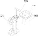
进一步的,所述废液处理机构14包括第四联动组件1401、第四驱动泵、第四转动杆1402和取液针1403,所述制片机构的一侧设置有所述第四联动组件1401,所述第四联动组件1401与所述第四转动杆1402的一端驱动连接,所述第四转动杆1402的另一端连接有所述取液针1403,所述第四驱动泵通过连接管与所述取液针1403相连接。Further, the waste
从上述描述可知,有利于当需要对一次性制片器内的废液进行抽取时,可运行第四联动组件1401,使第四联动组件1401带动第四转动杆1402和取液针1403转移至一次性制片器上方,随后第四联动组件1401带动第四转动杆1402和取液针1403下降,并使第四驱动泵通过连接管和取液针1403对废液进行抽取,随后通过清洗机构对取液针1403的内壁和外壁进行清洗,并依次对各个一次性制片器进行抽取废液。It can be seen from the above description that when it is necessary to extract the waste liquid in the disposable tablet, the
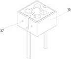
进一步的,所述清洗机构包括第一清洗槽11、第二清洗槽17、第三清洗槽3、第四清洗槽15、清洗泵组31、电磁阀组16和废液泵32,所述第一清洗槽11、所述第二清洗槽17、所述第三清洗槽3和所述第四清洗槽15的外侧均设置有进水口27,一所述清洗泵组31通过连接管与一所述进水口27相连接,所述第一清洗槽11、所述第二清洗槽17、所述第三清洗槽3和所述第四清洗槽15的底部均设置有排水口,一所述废液泵32与一所述排水口相连接。Further, the cleaning mechanism includes a
从上述描述可知,有利于当需要对各个针管进行清洗时可将对应的针管伸入对应的清洗槽内,随后运行清洗泵组31,使清洗泵组31将清水通过连接管导入对应的清洗槽内,并对针管的外壁进行清洗,同时连接管上设置有分叉管,一分叉管通过电磁阀组16与一对应的针管相连接,在清洗的同时电磁阀组16上对应的电磁阀打开,清洗泵组31将清水通过分叉管导入针管内部,并对针管内壁进行清洗,并通过废液泵32将清洗后的废水通过排水口抽出,并通过废液泵32将清洗后的废水排出。It can be seen from the above description that when each needle tube needs to be cleaned, the corresponding needle tube can be inserted into the corresponding cleaning tank, and then the
进一步的,还包括处理液储存机构2,所述处理液储存机构2与所述清洗机构和所述样本处理装置相连接,所述处理液储存机构2包括容纳箱202、电磁阀、清水瓶201、密度液瓶、染色液瓶、透明液瓶和分化液瓶,所述清水瓶201、密度液瓶、染色液瓶、透明液瓶和分化液瓶均设置于所述容纳箱202内部,所述密度液瓶、染色液瓶、透明液瓶和分化液瓶分别通过一电磁阀与所述样本处理装置相连接,所述清水瓶201通过电磁阀与所述清洗机构相连接。Further, it also includes a processing
从上述描述可知,有利于当清洗机构需要抽取清水瓶201内的清水进行清洗时,清水瓶201上对应的电磁阀将接通,并通过清洗泵组31将清水瓶201内的清水抽出,当样本处理装置需要抽取处理液时,相应的处理液上的电磁阀将接通,随后样本处理装置对相应的处理液进行抽取。进一步的,还包括控制器8,所述控制器8分别与所述分离机构、制片机构、样本处理装置和清洗机构电连接。It can be seen from the above description that when the cleaning mechanism needs to extract the clean water in the
从上述描述可知,有利于使用者在控制整体装置时更加的便捷。As can be seen from the above description, it is beneficial for the user to control the overall device more conveniently.
实施例一Example 1
请参照图1至图15,一种液基细胞样本制作装置,包括机台1、分离机构、制片机构、样本处理装置和清洗机构,所述机台1的一侧设置有所述分离机构,所述机台1的另一侧设置有所述制片机构,所述样本处理装置与所述机台1相连接,所述清洗机构与所述样本处理装置相连接;1 to 15, a liquid-based cell sample preparation device includes a
所述样本处理装置包括密度液控制机构5、样本转移机构10、样本染色、分化、透明机构4和废液处理机构14;The sample processing device includes a density
所述分离机构包括第一旋转驱动件、第一基座、第一托盘6和平衡式离心盘,所述第一托盘6通过所述第一基座与所述机台1的一侧相连接,所述第一基座通过螺丝与所述机台1的一侧可拆卸,所述平衡式离心盘通过转轴可转动连接于所述第一托盘6内部,所述第一旋转驱动件与所述平衡式离心盘驱动连接;The separation mechanism includes a first rotary drive member, a first base, a
所述第一旋转驱动件通过联轴器与所述转轴驱动连接;The first rotary driving member is drivingly connected with the rotating shaft through a coupling;
所述平衡式离心盘包括盘体7、双孔样本架19、轴杆18和固定耳架20,所述盘体7的外侧环绕设置有若干个容纳槽21,所述容纳槽21共设置有18个,所述容纳槽21的两侧分别通过螺丝可拆卸连接有一所述固定耳架20,所述双孔样本架19上部的两侧分别固定连接有一所述轴杆18,一所述轴杆18与一所述固定耳架20可转动连接,所述固定耳架20内部设置有轴套,所述固定耳架20通过所述轴套与所述轴杆18可转动连接;The balanced centrifugal disc includes a
所述转轴通过螺丝与所述盘体7可拆卸连接;The rotating shaft is detachably connected to the
所述制片机构包括第二旋转驱动件、第二基座、第二托盘12和双层制片盘,所述第二托盘12通过所述第二基座与所述机台1的另一侧相连接,所述第二基座通过螺丝与所述机台1的另一侧可拆卸连接,所述双层制片盘通过转轴可转动连接于所述第二托盘12内部,所述第二旋转驱动件与所述双层制片盘驱动连接;The film-making mechanism includes a second rotary drive member, a second base, a
所述第二旋转驱动件通过联轴器与所述双层制片盘驱动连接;The second rotary driving member is drivingly connected with the double-layer filming disc through a coupling;
所述第一旋转驱动件与所述第二旋转驱动件均为步进电机;Both the first rotary driving member and the second rotary driving member are stepper motors;
所述双层制片盘包括上盘13和下盘23,所述上盘13通过固定杆与所述下盘23相连接,所述上盘13上环绕设置有若干个制片孔22,所述制片孔22共设置有36个,所述下盘23上相对设置有若干个卡槽24,所述制片孔22用于容纳一次性制片器,所述卡槽24用于限制一次性制片器在离心时晃动;The double-layer film-making disk includes an
所述一次性制片器包括玻片卡29、载玻片30和弯头28,所述玻片卡29内部设置有片槽,所述载玻片30设置于所述片槽内,所述片槽外表面设置有开口,所述弯头28通过卡块与所述开口相连接;The disposable slide device includes a
所述玻片卡29的上部穿设于于所述制片孔22内,所述玻片卡29的下部卡接于所述卡槽24内;The upper part of the
所述样本转移机构10包括第一联动组件101、第一驱动泵9、第一转动杆102和转移针103,所述分离机构和所述制片机构之间设置有所述第一联动组件101,所述第一联动组件101与所述第一转动杆102的一端驱动连接,所述第一转动杆102的另一端安装有所述转移针103,所述第一驱动泵9的一侧通过电磁阀与所述转移针103相连接;The
所述第一驱动泵9的另一侧通过连接管与清水瓶201相连接,有利于通过持续的排水清洗转移针103内壁;The other side of the
所述第一驱动泵9为定量柱塞泵,有利于对样品进行定量吸取;The
所述密度液控制机构5包括第二联动组件501、第二驱动泵、第二转动杆502和密度液针503,所述分离机构的一侧设置有所述第二联动组件501,所述第二联动组件501与所述第二转动杆502的一端驱动连接,所述第二转动杆502的另一端连接有所述密度液针503,一所述第二驱动泵通过连接管与所述密度液针503相连接;The density
还包括排液针,另一所述第二驱动泵通过连接管与所述排液针相连接,所述排液针用于吸取分离后的密度液,并将分离后的密度液排出;It also includes a liquid discharge needle, and the other second driving pump is connected with the liquid discharge needle through a connecting pipe, and the liquid discharge needle is used to absorb the separated density liquid and discharge the separated density liquid;
所述排液针的外表面与所述密度液针503的外表面相贴合;The outer surface of the liquid discharge needle is in contact with the outer surface of the
所述排液针和所述密度液针503共设置有两组,有利于同时对两个一次性样品瓶25内的样品进行处理,提升处理速度;There are two sets of the liquid discharge needle and the
另一所述第二驱动泵通过连接管与清水瓶201相连接,有利于通过持续的排水清洗排液针内壁;The other said second driving pump is connected to the
所述样本染色、分化、透明机构4包括第三联动组件、第三驱动泵、第三转动杆、染色针、透明针和分化针,所述制片机构的一侧设置有所述第三联动组件,所述第三联动组件与所述第三转动杆的一端驱动连接,所述第三转动杆的另一端连接有所述染色针、透明针和分化针,一第三驱动泵通过连接管与所述染色针相连接,一第三驱动泵通过连接管与所述透明针相连接,一第三驱动泵通过连接管与所述分化针相连接;The sample dyeing, differentiation, and
所述染色针、所述透明针和所述分化针共设置有两组,有利于同时对两个一次性制片器内的样品进行处理,提升处理速度;There are two groups of dyeing needles, transparent needles and differentiation needles, which is beneficial to process the samples in the two disposable tableters at the same time and improve the processing speed;
单组所述染色针、所述透明针和所述分化针均通过扎带紧密贴合,有利于更好的进入一次性制片器内;The dyeing needles, the transparent needles and the differentiation needles in a single group are tightly attached by a tie, which is conducive to better entry into the disposable tablet device;
在对染色针、透明针和分化针进行清洗时,可通过持续对染色针、透明针和分化针内部输入过量的液体,用于达到清洗的目的;When cleaning the dyeing needles, transparent needles and differentiation needles, the purpose of cleaning can be achieved by continuously inputting excess liquid into the interior of the dyeing needles, transparent needles and differentiation needles;
所述废液处理机构14包括第四联动组件1401、第四驱动泵、第四转动杆1402和取液针1403,所述制片机构的一侧设置有所述第四联动组件1401,所述第四联动组件1401与所述第四转动杆1402的一端驱动连接,所述第四转动杆1402的另一端连接有所述取液针1403,所述第四驱动泵的一侧通过连接管与所述取液针1403相连接;The waste
所述取液针1403共设置有4组,有利于同时对四个一次性制片器内的废液进行处理,提升处理速度;There are 4 groups of the liquid-taking
所述第四驱动泵的一侧通过连接管与清水瓶201相连接,有利于通过持续的排水清洗取液针1403内壁;One side of the fourth driving pump is connected to the
所述第二驱动泵、所述第三驱动泵和所述第四驱动泵均为糯动泵;The second drive pump, the third drive pump and the fourth drive pump are all dynamic pumps;
所述废液处理机构14还包括针座1404,所述针座1404与所述第四转动杆1402的另一端相焊接,所述取液针1403均与所述针座1404相连接;The waste
所述转移针103、所述密度液针503、所述染色针、透明针和分化针内外表面均采用铁氟龙工艺处理,所述连接管均采用四氟聚乙烯材质,均具有优良的抗粘附性,防止样品残留,避免交叉感染;The inner and outer surfaces of the
所述第一联动组件101、所述第二联动组件501、所述第三联动组件和所述第四联动组件1401结构相同;The
所述第一联动组件101包括底板10105、顶板10107、支撑板10109、升降驱动步进电机10110、转动驱动步进电机10108、驱动杆10101和齿轮盘10102,所述底板10105通过所述支撑板10109与所述顶板10107相连接,所述底板10105通过螺丝与所述机台1可拆卸连接,所述顶板10107的一侧安装有所述转动驱动步进电机10108,所述顶板10107的另一侧可转动连接有所述齿轮盘10102,所述驱动杆10101上设置有限位滑槽,所述齿轮盘10102内部设置有容纳孔,所述容纳孔内设置有限位滑块,所述驱动杆10101滑动穿设于所述容纳孔内,所述限位滑槽和所述限位滑块用于齿轮盘10102带动驱动杆10101转动,所述转动驱动步进电机10108通过同步带10106与所述齿轮盘10102驱动连接,所述支撑板10109上可拆卸连接有固定板,所述固定板的上部连接有转轮,所述固定板的下部水平安装有所述升降驱动步进电机10110,所述升降驱动步进电机10110通过传动带10111与所述转轮驱动连接,所述驱动杆10101的底部安装有轴承套10103,所述轴承套10103通过连接臂10104与所述传动带10111相连接,所述驱动杆10101的顶部安装有所述第一转动杆102;The first linkage assembly 101 includes a bottom plate 10105 , a top plate 10107 , a support plate 10109 , a lifting and driving stepper motor 10110 , a rotation driving stepper motor 10108 , a driving rod 10101 and a gear plate 10102 , and the bottom plate 10105 passes through the supporting plate 10109 Connected to the top plate 10107, the bottom plate 10105 is detachably connected to the machine table 1 through screws, the rotary drive stepping motor 10108 is installed on one side of the top plate 10107, and the other side of the top plate 10107 The gear plate 10102 is rotatably connected, the drive rod 10101 is provided with a limit chute, the gear plate 10102 is provided with an accommodation hole inside, and a limit slider is arranged in the accommodation hole, and the drive rod 10101 slides Passing through the accommodating hole, the limit chute and the limit slider are used for the gear plate 10102 to drive the drive rod 10101 to rotate, and the rotation drives the stepping motor 10108 to communicate with the gear plate through the synchronous belt 10106 10102 drive connection, the support plate 10109 is detachably connected with a fixed plate, the upper part of the fixed plate is connected with a runner, and the lower part of the fixed plate is horizontally installed with the lift drive stepping motor 10110, the lift drive The stepper motor 10110 is drivingly connected to the runner through a transmission belt 10111, a bearing sleeve 10103 is installed at the bottom of the driving rod 10101, and the bearing sleeve 10103 is connected to the transmission belt 10111 through a connecting arm 10104, and the driving rod 10101 The top of the first rotating rod 102 is installed;
当需要控制第一转动杆102升降时可通过升降驱动步进电机10110运行带动传动带10111运行,同时传动带10111通过连接臂10104带动轴承套10103与驱动杆10101进行升降,并控制第一转动杆102进行升降,当需要控制第一转动杆102转动时,可通过运行转动驱动步进电机10108,使转动驱动步进电机10108通过同步带10106带动齿轮盘10102转动,并通过齿轮盘10102带动驱动杆10101和第一转动杆102转动;When it is necessary to control the lifting and lowering of the first
所述清洗机构包括第一清洗槽11、第二清洗槽17、第三清洗槽3、第四清洗槽15、清洗泵组31、电磁阀组16和废液泵32,所述第一清洗槽11、所述第二清洗槽17、所述第三清洗槽3和所述第四清洗槽15的外侧均设置有进水口27,一所述清洗泵组31通过连接管与一所述进水口27相连接,所述第一清洗槽11、所述第二清洗槽17、所述第三清洗槽3和所述第四清洗槽15的底部均设置有排水口,一所述废液泵32与一所述排水口相连接;The cleaning mechanism includes a
所述第一清洗槽11、第二清洗槽17、第三清洗槽3和第四清洗槽15用于清洗针管的外表面;The
所述第一清洗槽11为单孔槽,所述第一清洗槽11设置于所述转移针103下方,所述第二清洗槽17和所述第三清洗槽3均为双孔槽,所述第二清洗槽17设置于所述密度液针503下方,所述第三清洗槽3设置于所述染色针、透明针和分化针下方,所述第四清洗槽15为四孔槽,所述第四清洗槽15设置于所述取液针1403下方;The
所述第一清洗槽11底部设置有安装板26,所述安装板26通过支撑杆与所述机台1相连接,所述第二清洗槽17、所述第三清洗槽3和所述第四清洗槽15分别通过一支撑杆与所述机台1相连接;还包括处理液储存机构2,所述处理液储存机构2与所述清洗机构和所述样本处理装置相连接,所述处理液储存机构2包括容纳箱202、电磁阀、清水瓶201、密度液瓶、染色液瓶、透明液瓶和分化液瓶,所述清水瓶201、密度液瓶、染色液瓶、透明液瓶和分化液瓶均设置于所述容纳箱202内部,所述密度液瓶、染色液瓶、透明液瓶和分化液瓶分别通过一电磁阀与所述样本处理装置相连接,所述清水瓶201通过电磁阀与所述清洗机构相连接;The bottom of the
所述清洗泵组31均通过连接管与所述清水瓶201相连接;The
所述第二驱动泵的一侧通过连接管的一端与所述密度液瓶相连接,所述第二驱动泵的另一侧通过连接管的另一端与所述密度液针503相连接;One side of the second driving pump is connected with the density liquid bottle through one end of the connecting pipe, and the other side of the second driving pump is connected with the
一所述第三驱动泵的一侧通过连接管的一端与所述染色液瓶相连接,一所述第三驱动泵的另一侧通过连接管的另一端与所述染色针相连接;One side of the third driving pump is connected with the dyeing liquid bottle through one end of the connecting pipe, and the other side of the third driving pump is connected with the dyeing needle through the other end of the connecting pipe;
一所述第三驱动泵的一侧通过连接管的一端与所述透明液瓶相连接,一所述第三驱动泵的另一侧通过连接管的另一端与所述透明针相连接;One side of the third driving pump is connected with the transparent liquid bottle through one end of the connecting pipe, and the other side of the third driving pump is connected with the transparent needle through the other end of the connecting pipe;
一所述第三驱动泵的一侧通过连接管的一端与所述分化液瓶相连接,一所述第三驱动泵的另一侧通过连接管的另一端与所述分化针相连接;One side of the third driving pump is connected with the differentiation liquid bottle through one end of the connecting pipe, and the other side of the third driving pump is connected with the differentiation needle through the other end of the connecting pipe;
还包括控制器8,所述控制器8分别与所述分离机构、制片机构、样本处理装置和清洗机构电连接。A
以上仅为本发明的实施例,并非因此限制本发明的专利范围,凡是利用本发明说明书及附图内容所作的等同变换,或直接或间接运用在相关的技术领域,均同理包括在本发明的专利保护范围内。The above are only the embodiments of the present invention, and are not intended to limit the scope of the present invention. Any equivalent transformation made by using the contents of the description and drawings of the present invention, or directly or indirectly applied in the relevant technical fields, are similarly included in the present invention. within the scope of patent protection.
此外,应当理解,虽然本说明书按照实施方式加以描述,但并非每个实施方式仅包含一个独立的技术方案,说明书的这种叙述方式仅仅是为清楚起见,本领域技术人员应当将说明书作为一个整体,各实施例中的技术方案也可以经适当组合,形成本领域技术人员可以理解的其他实施方式。In addition, it should be understood that although this specification is described in terms of embodiments, not each embodiment only includes an independent technical solution, and this description in the specification is only for the sake of clarity, and those skilled in the art should take the specification as a whole , the technical solutions in each embodiment can also be appropriately combined to form other implementations that can be understood by those skilled in the art.
Claims (10)
Priority Applications (1)
| Application Number | Priority Date | Filing Date | Title |
|---|---|---|---|
| CN202111482993.7ACN114371052A (en) | 2021-12-07 | 2021-12-07 | A liquid-based cell sample preparation device |
Applications Claiming Priority (1)
| Application Number | Priority Date | Filing Date | Title |
|---|---|---|---|
| CN202111482993.7ACN114371052A (en) | 2021-12-07 | 2021-12-07 | A liquid-based cell sample preparation device |
Publications (1)
| Publication Number | Publication Date |
|---|---|
| CN114371052Atrue CN114371052A (en) | 2022-04-19 |
Family
ID=81139440
Family Applications (1)
| Application Number | Title | Priority Date | Filing Date |
|---|---|---|---|
| CN202111482993.7APendingCN114371052A (en) | 2021-12-07 | 2021-12-07 | A liquid-based cell sample preparation device |
Country Status (1)
| Country | Link |
|---|---|
| CN (1) | CN114371052A (en) |
Cited By (2)
| Publication number | Priority date | Publication date | Assignee | Title |
|---|---|---|---|---|
| TWI836596B (en)* | 2022-09-12 | 2024-03-21 | 貝索企業有限公司 | Intelligent multi-channel patch dyeing machine and patch dyeing method |
| CN118376803A (en)* | 2024-06-26 | 2024-07-23 | 长沙远安生物科技有限公司 | Sample injection device for liquid-based thin-layer cell pelleter |
Citations (8)
| Publication number | Priority date | Publication date | Assignee | Title |
|---|---|---|---|---|
| CN202002835U (en)* | 2010-09-13 | 2011-10-05 | 南京卡博生物科技有限公司 | Centrifugal smear liquid-based cell sheet processing dyeing machine |
| CN203908840U (en)* | 2014-06-09 | 2014-10-29 | 马艳华 | Microcomputer-controlled liquid-based cell sheet preparation dyeing system |
| CN204064766U (en)* | 2014-09-24 | 2014-12-31 | 三明市和众生物技术有限公司 | A kind of Full Automatic Liquid basal cell length of schooling sheet coloring system |
| KR20160099295A (en)* | 2015-02-12 | 2016-08-22 | (주)로봇앤드디자인 | Staining apparatus for cell |
| CN106018033A (en)* | 2016-07-04 | 2016-10-12 | 邱加伟 | Fully automatic thinprep cytology processing and dyeing device |
| CN207923560U (en)* | 2018-03-21 | 2018-09-28 | 深圳市鹏一医疗仪器有限公司 | Automatic staining machine film-making loader and full-automatic liquid-based cell sample manufacturing dye all-in-one machine |
| CN108931415A (en)* | 2017-05-23 | 2018-12-04 | 北京诚智光辉科技有限公司 | Sectioning cells with wiper mechanism dye all-in-one machine |
| CN112326387A (en)* | 2020-11-19 | 2021-02-05 | 深路医学科技(武汉)有限公司 | A liquid-based cell preparation device |
- 2021
- 2021-12-07CNCN202111482993.7Apatent/CN114371052A/enactivePending
Patent Citations (8)
| Publication number | Priority date | Publication date | Assignee | Title |
|---|---|---|---|---|
| CN202002835U (en)* | 2010-09-13 | 2011-10-05 | 南京卡博生物科技有限公司 | Centrifugal smear liquid-based cell sheet processing dyeing machine |
| CN203908840U (en)* | 2014-06-09 | 2014-10-29 | 马艳华 | Microcomputer-controlled liquid-based cell sheet preparation dyeing system |
| CN204064766U (en)* | 2014-09-24 | 2014-12-31 | 三明市和众生物技术有限公司 | A kind of Full Automatic Liquid basal cell length of schooling sheet coloring system |
| KR20160099295A (en)* | 2015-02-12 | 2016-08-22 | (주)로봇앤드디자인 | Staining apparatus for cell |
| CN106018033A (en)* | 2016-07-04 | 2016-10-12 | 邱加伟 | Fully automatic thinprep cytology processing and dyeing device |
| CN108931415A (en)* | 2017-05-23 | 2018-12-04 | 北京诚智光辉科技有限公司 | Sectioning cells with wiper mechanism dye all-in-one machine |
| CN207923560U (en)* | 2018-03-21 | 2018-09-28 | 深圳市鹏一医疗仪器有限公司 | Automatic staining machine film-making loader and full-automatic liquid-based cell sample manufacturing dye all-in-one machine |
| CN112326387A (en)* | 2020-11-19 | 2021-02-05 | 深路医学科技(武汉)有限公司 | A liquid-based cell preparation device |
Non-Patent Citations (1)
| Title |
|---|
| 王珑 等: ""在宫颈癌筛查中液基细胞学制片方法及染色法探讨"", 《实验与检验医学》, no. 04, 15 August 2017 (2017-08-15)* |
Cited By (2)
| Publication number | Priority date | Publication date | Assignee | Title |
|---|---|---|---|---|
| TWI836596B (en)* | 2022-09-12 | 2024-03-21 | 貝索企業有限公司 | Intelligent multi-channel patch dyeing machine and patch dyeing method |
| CN118376803A (en)* | 2024-06-26 | 2024-07-23 | 长沙远安生物科技有限公司 | Sample injection device for liquid-based thin-layer cell pelleter |
Similar Documents
| Publication | Publication Date | Title |
|---|---|---|
| CN111735978A (en) | Fully automatic chemiluminescence immunoassay analyzer | |
| CN204064766U (en) | A kind of Full Automatic Liquid basal cell length of schooling sheet coloring system | |
| EP0465832B1 (en) | Method and apparatus for preparing cells for examination | |
| CN203908840U (en) | Microcomputer-controlled liquid-based cell sheet preparation dyeing system | |
| US5240606A (en) | Apparatus for preparing cells for examination | |
| CN114371052A (en) | A liquid-based cell sample preparation device | |
| CN201449349U (en) | Automatic liquid based lamina cell smear machine | |
| CN115112912B (en) | A multi-item body fluid analyzer | |
| CN216838008U (en) | Cell preparation system | |
| CN105021441B (en) | Automatic smear overflow dyeing machine | |
| WO2022073335A1 (en) | Fully automated method for production of exfoliated cells | |
| CN116099669A (en) | Clinical laboratory blood analysis structure with blood centrifugal separation function | |
| CN215296875U (en) | Automatic slide dyeing machine | |
| CN220136791U (en) | Liquid-based thin-layer cell slice-making and dyeing integrated machine | |
| CN212646715U (en) | Full-automatic analyzer | |
| CN110794157A (en) | Tester for anionic surfactant in water | |
| CN109443889B (en) | Full-automatic push-piece dyeing system | |
| CN209166961U (en) | A kind of dyeing of microsection manufacture and scanning integrated machine | |
| CN116571361A (en) | A urine sample detection test centrifuge processing system for realizing the separation of urine sediment | |
| CN217931701U (en) | Multi-project body fluid analyzer | |
| CN218674435U (en) | Cell film-making dyeing machine | |
| CN113324824A (en) | Cell transfer device and cell transfer and pretreatment method | |
| CN217238115U (en) | A new type of test sample transfer device | |
| CN214794479U (en) | Detection module | |
| CN219117463U (en) | Cell culture isolator |
Legal Events
| Date | Code | Title | Description |
|---|---|---|---|
| PB01 | Publication | ||
| PB01 | Publication | ||
| SE01 | Entry into force of request for substantive examination | ||
| SE01 | Entry into force of request for substantive examination |