CN114370852A - Accurate evaluation method and system for working face well-ground combined test ground subsidence basin - Google Patents
Accurate evaluation method and system for working face well-ground combined test ground subsidence basinDownload PDFInfo
- Publication number
- CN114370852A CN114370852ACN202111532797.6ACN202111532797ACN114370852ACN 114370852 ACN114370852 ACN 114370852ACN 202111532797 ACN202111532797 ACN 202111532797ACN 114370852 ACN114370852 ACN 114370852A
- Authority
- CN
- China
- Prior art keywords
- ground
- data
- working face
- settlement
- optical fiber
- Prior art date
- Legal status (The legal status is an assumption and is not a legal conclusion. Google has not performed a legal analysis and makes no representation as to the accuracy of the status listed.)
- Granted
Links
- 238000012360testing methodMethods0.000titleclaimsabstractdescription101
- 238000011156evaluationMethods0.000titleclaimsabstractdescription22
- 238000005553drillingMethods0.000claimsabstractdescription60
- 238000005065miningMethods0.000claimsabstractdescription55
- 239000013307optical fiberSubstances0.000claimsabstractdescription53
- 238000000034methodMethods0.000claimsabstractdescription50
- 238000012806monitoring deviceMethods0.000claimsabstractdescription39
- 239000003245coalSubstances0.000claimsabstractdescription25
- 230000008569processEffects0.000claimsabstractdescription22
- 238000006073displacement reactionMethods0.000claimsabstractdescription21
- 238000011161developmentMethods0.000claimsabstractdescription19
- 238000007405data analysisMethods0.000claimsabstractdescription18
- 238000012544monitoring processMethods0.000claimsabstractdescription17
- 238000011084recoveryMethods0.000claimsabstractdescription8
- 239000000835fiberSubstances0.000claimsdescription17
- 238000009434installationMethods0.000claimsdescription15
- 230000008859changeEffects0.000claimsdescription10
- 229910000831SteelInorganic materials0.000claimsdescription4
- 239000010959steelSubstances0.000claimsdescription4
- 238000000605extractionMethods0.000claims8
- 238000004062sedimentationMethods0.000claims1
- 238000012546transferMethods0.000claims1
- 230000015572biosynthetic processEffects0.000description19
- 238000010276constructionMethods0.000description7
- 230000006872improvementEffects0.000description7
- 239000011435rockSubstances0.000description5
- 238000005516engineering processMethods0.000description4
- 238000004458analytical methodMethods0.000description3
- 238000013480data collectionMethods0.000description3
- 238000010586diagramMethods0.000description3
- 230000007613environmental effectEffects0.000description3
- 239000003550markerSubstances0.000description3
- 230000005540biological transmissionEffects0.000description2
- 238000004364calculation methodMethods0.000description2
- 230000001186cumulative effectEffects0.000description2
- 230000002354daily effectEffects0.000description2
- 238000013101initial testMethods0.000description2
- 238000005259measurementMethods0.000description2
- 230000007246mechanismEffects0.000description2
- 238000011160researchMethods0.000description2
- 230000004044responseEffects0.000description2
- 230000009286beneficial effectEffects0.000description1
- 238000012937correctionMethods0.000description1
- 238000011157data evaluationMethods0.000description1
- 238000013461designMethods0.000description1
- 230000003203everyday effectEffects0.000description1
- 230000010354integrationEffects0.000description1
- 238000012986modificationMethods0.000description1
- 230000004048modificationEffects0.000description1
- 239000007787solidSubstances0.000description1
- 238000010998test methodMethods0.000description1
- 238000012795verificationMethods0.000description1
Images


Classifications
- G—PHYSICS
- G01—MEASURING; TESTING
- G01C—MEASURING DISTANCES, LEVELS OR BEARINGS; SURVEYING; NAVIGATION; GYROSCOPIC INSTRUMENTS; PHOTOGRAMMETRY OR VIDEOGRAMMETRY
- G01C5/00—Measuring height; Measuring distances transverse to line of sight; Levelling between separated points; Surveyors' levels
- G—PHYSICS
- G01—MEASURING; TESTING
- G01B—MEASURING LENGTH, THICKNESS OR SIMILAR LINEAR DIMENSIONS; MEASURING ANGLES; MEASURING AREAS; MEASURING IRREGULARITIES OF SURFACES OR CONTOURS
- G01B11/00—Measuring arrangements characterised by the use of optical techniques
- G01B11/16—Measuring arrangements characterised by the use of optical techniques for measuring the deformation in a solid, e.g. optical strain gauge
- G01B11/18—Measuring arrangements characterised by the use of optical techniques for measuring the deformation in a solid, e.g. optical strain gauge using photoelastic elements
Landscapes
- Physics & Mathematics (AREA)
- General Physics & Mathematics (AREA)
- Engineering & Computer Science (AREA)
- Radar, Positioning & Navigation (AREA)
- Remote Sensing (AREA)
- Testing Or Calibration Of Command Recording Devices (AREA)
- Investigation Of Foundation Soil And Reinforcement Of Foundation Soil By Compacting Or Drainage (AREA)
Abstract
Description
Translated fromChinese技术领域technical field
本发明涉及煤矿工作面监测技术领域,尤其涉及一种工作面井地联合测试地面沉降盆地的精确评价方法及系统。The invention relates to the technical field of coal mine working face monitoring, in particular to an accurate evaluation method and system for jointly testing ground subsidence basins on working faces and wells.
背景技术Background technique
煤炭作为我国主体能源,在国民经济和社会发展中发挥了举足轻重的作用。但是大规模的煤炭资源开采带来了采动损害及广泛的环境效应。特别是随着采煤沉陷形成地面沉降盆地,造成得地质环境恶化,耕地数量减少,建(构)筑物受损,易地搬迁等人地矛盾的问题日益突出,同时还带来了不良的社会影响。如何对沉陷盆地发育过程进行动态评价是采煤塌陷地治理工作中重要的环节,对于推进矿山地质环境修复和矿区土地复垦意义重大。Coal, as the main energy source in my country, has played a pivotal role in national economic and social development. However, large-scale coal mining has brought mining damage and extensive environmental effects. In particular, with coal mining subsidence forming land subsidence basins, the geological environment deteriorates, the amount of arable land is reduced, buildings (structures) are damaged, and the problems of conflicts between people and land, such as relocation, are becoming more and more prominent. social influence. How to dynamically evaluate the development process of the subsidence basin is an important link in the management of coal mining subsidence, and it is of great significance to promote the restoration of the mine geological environment and the land reclamation in the mining area.
现有采煤沉降盆地调研的通常针对地表沉陷进行的,其中水准测量、GNSS是常用的观测方法,上述两种数据采集受测试地形影响严重,在微变形观测的实现上存在观测成本高,测试数据评价难度大,离散数据干扰影响严重的问题;随着测试技术发展InSAR技术的发展促进了地表沉降观测评价分析方法的极大进步,能够实现全天候、全天时、高精度、连续空间覆盖等等特点。InSAR空间测试技术能够很好捕捉地表垂直方向位移变化,然而对于岩层内部移动参数的获取依然是存在一定难度。对于岩层内部岩移测试而言,主要采用方法有Sondex观测法、钻孔多点位移计、基岩标、分层标等测试方法,其中上述方法施工量大,并均存在数据采集难度大、难以实现动态监测的问题,测试周期和测试控制距离相对较短,不利于大数据、大样本量精确分析。在理论研究上主要以概率积分法和随机介质法为主,但是理论研究主要用作预计,最终沉降盆地的实际情况与预计结果往往会存在较大的偏差,而且,对于特殊的厚松散层以及急倾斜煤层的适用性也略显不足,其对于岩移内部变形问题的解决也是存在局限性的。虽然上述方法在实测中已经得到广泛应用,但是由于地层沉降变形的影响,测试数据偏差大,对于地面沉降盆地地层内部变形评价依然存在难以量化测试的难题,不利于精确定量得到地层内部变形岩移参数的获取。Existing coal mining subsidence basin surveys are usually carried out for surface subsidence, among which leveling and GNSS are commonly used observation methods. The above two data acquisitions are seriously affected by the test terrain, and the realization of micro-deformation observation has high observation costs and testing. Data evaluation is difficult, and discrete data interference is seriously affected; with the development of testing technology, the development of InSAR technology has promoted great progress in surface subsidence observation, evaluation and analysis methods, which can achieve all-weather, all-day, high-precision, continuous space coverage, etc. Features. The InSAR space test technology can capture the vertical displacement changes of the surface well, but it is still difficult to obtain the internal movement parameters of the rock formation. For the internal rock movement test of the rock formation, the main methods are Sondex observation method, drilling multi-point displacement meter, bedrock mark, layered mark and other test methods, among which the above methods have a large amount of construction, and all have difficulties in data collection, It is difficult to realize the problem of dynamic monitoring, and the test cycle and test control distance are relatively short, which is not conducive to the accurate analysis of big data and large sample size. In theoretical research, the probability integration method and random medium method are mainly used, but theoretical research is mainly used for prediction, and the actual situation of the final subsidence basin often has a large deviation from the expected results. Moreover, for special thick loose layers and The applicability of steeply inclined coal seams is also slightly insufficient, and it also has limitations in solving the internal deformation problem of rock movement. Although the above methods have been widely used in actual measurement, due to the influence of stratum subsidence and deformation, the deviation of test data is large, and it is still difficult to quantitatively test the evaluation of internal stratum deformation in ground subsidence basins, which is not conducive to accurately and quantitatively obtain the deformation and rock movement inside the stratum. Get the parameters.
发明内容SUMMARY OF THE INVENTION
本发明的目的在于提供一种工作面井地联合测试地面沉降盆地的精确评价方法,以解决上述背景技术中提出的问题。The purpose of the present invention is to provide an accurate evaluation method for joint testing of ground subsidence basins on working face, well and ground, so as to solve the problems raised in the above background technology.
为实现上述目的,本发明所采取的技术方案是:To achieve the above object, the technical scheme adopted by the present invention is:
一方面,提供了一种工作面井地联合测试地面沉降盆地的精确评价方法,所述地面沉降盆地位于地面上,所述方法包括:In one aspect, there is provided an accurate evaluation method for joint testing of ground subsidence basins on the working face, wells and ground, where the ground subsidence basins are located on the ground, and the method includes:
步骤一、布置分布式测试系统:Step 1. Arrange the distributed test system:
所述分布式测试系统包括:与工作面走向中心线平行的地面测线、分别位于预测-10mm沉降线内部和外部的第一竖向钻孔和第二竖向钻孔,所述地面测线投影与所述工作面走向中心线在同一竖直平面内;The distributed testing system includes: a ground survey line parallel to the centerline of the working face, a first vertical borehole and a second vertical borehole located inside and outside the predicted -10mm settlement line, respectively, the ground survey line. The projection is in the same vertical plane as the working face going to the center line;
步骤二、布置数据采集系统:Step 2. Arrange the data acquisition system:
在所述-10mm沉降线内部的地面测线上依次间隔布置多个沉降监测装置;Arrange a plurality of settlement monitoring devices at intervals on the ground survey line inside the -10mm settlement line in sequence;
在所述-10mm沉降线外侧安装沉降数据采集装置,通过沉降数据采集装置获取煤层采动过程中地面测线上布置的每个沉降监测装置的空间位置数据;A subsidence data acquisition device is installed outside the -10mm subsidence line, and the spatial position data of each subsidence monitoring device arranged on the ground survey line during the coal seam mining process is obtained through the subsidence data acquisition device;
分别在所述第一竖向钻孔和第二竖向钻孔内部布置若干光纤传感器,形成分布式光纤传感器,记录每个光纤传感器的安装坐标;将钻孔数据采集模块与所有的光纤传感器连接,以通过钻孔数据采集模块获取每个光纤传感器发送的用于表征地层内部变形数据的测试值;Arrange a number of optical fiber sensors in the first vertical borehole and the second vertical borehole respectively to form distributed optical fiber sensors, record the installation coordinates of each optical fiber sensor; connect the drilling data acquisition module with all the optical fiber sensors , to obtain the test value sent by each optical fiber sensor to characterize the deformation data inside the formation through the borehole data acquisition module;
步骤三、数据分析系统评价:Step 3. Data analysis system evaluation:
数据分析系统根据已有地质资料、由激光测试装置在不同监测时刻发送的多组位移数据、地面钻孔数据采集装置在不同监测时刻发送的多组地层内部变形数据、工作面初始位置、以及输入的工作面回采位置数据对预测沉降盆地变形和发育情况进行评价。The data analysis system is based on the existing geological data, multiple sets of displacement data sent by the laser testing device at different monitoring times, multiple sets of formation internal deformation data sent by the ground borehole data acquisition device at different monitoring times, the initial position of the working face, and input The mining location data of the working face can be used to evaluate the deformation and development of the predicted subsidence basin.
作为本发明的进一步改进,步骤一中,所述第一竖向钻孔和第二竖向钻孔均采用负压钻进方式通过地面施工至工作面顶板上方。As a further improvement of the present invention, in step 1, the first vertical borehole and the second vertical borehole are constructed to the top of the working face top plate through the ground by means of negative pressure drilling.
作为本发明的进一步改进,步骤二中,沉降监测装置包括:沉降基台、标志杆、激光反射器;As a further improvement of the present invention, in step 2, the settlement monitoring device includes: a settlement base, a marker pole, and a laser reflector;
其中,沉降基台底部埋地,顶部露出地面,标志杆设置在沉降基台的上表面,激光反射器布置于标志杆顶部。Among them, the bottom of the settlement base is buried, the top is exposed to the ground, the sign pole is arranged on the upper surface of the settlement base, and the laser reflector is arranged on the top of the sign pole.
作为本发明的进一步改进,步骤二中,激光测试装置包括第一激光测试模块和第二激光测试模块;所述在所述-10mm沉降线外侧安装沉降数据采集装置包括:As a further improvement of the present invention, in step 2, the laser test device includes a first laser test module and a second laser test module; the installation of the settlement data acquisition device outside the -10mm settlement line includes:
在所述工作面走向中心线的前侧、且位于所述第一竖向钻孔远离所述第二竖向钻孔的一侧处安装第一激光测试模块;installing a first laser test module on the front side of the working surface toward the centerline and at the side of the first vertical borehole away from the second vertical borehole;
在所述工作面走向中心线的后侧、且位于所述第二竖向钻孔远离所述第一竖向钻孔的一侧处安装第二激光测试模块。A second laser test module is installed on the back side of the working surface toward the centerline and at the side of the second vertical borehole away from the first vertical borehole.
作为本发明的进一步改进,步骤二中,分别在所述第一竖向钻孔和第二竖向钻孔内部布置若干光纤传感器,形成分布式光纤传感器,记录每个光纤传感器的安装坐标,包括:As a further improvement of the present invention, in step 2, a plurality of optical fiber sensors are respectively arranged inside the first vertical borehole and the second vertical borehole to form a distributed optical fiber sensor, and the installation coordinates of each optical fiber sensor are recorded, including :
在所述第一竖向钻孔和第二竖向钻孔内部依次下放若干光纤,下放完成后记录每个光纤的安装坐标,光纤传感器下放的方式如下:A number of optical fibers are placed in the first vertical borehole and the second vertical borehole in turn. After the placement is completed, the installation coordinates of each optical fiber are recorded. The way of placing the optical fiber sensor is as follows:
将光纤尾端固定于引导器上,并附着于钢绞线外侧,使用设有固设长度的钻杆导送引导器,钻杆导送为续接方式,每导送一次,续接一根钻杆;Fix the fiber end on the guide and attach it to the outside of the steel strand. Use a drill pipe guide with a fixed length. The drill pipe is guided by a continuous connection method. drill pipe;
通过计量钻杆续接数量获得每个光纤传感器的安装深度,通过第一钻孔的位置和第二钻孔的位置,获取每个光纤传感器的平面位置,基于所述安装深度和平面位置得到每个光纤传感器的位置坐标。The installation depth of each fiber optic sensor is obtained by measuring the number of drill pipe connections, the plane position of each fiber optic sensor is obtained through the position of the first hole and the position of the second hole, and each fiber sensor is obtained based on the installation depth and plane position. The location coordinates of the fiber optic sensors.
作为本发明的进一步改进,步骤二中,通过钻孔数据采集模块获取每个光纤传感器发送的用于表征地层内部变形数据的测试值,包括:As a further improvement of the present invention, in step 2, the test value sent by each optical fiber sensor for characterizing the deformation data inside the formation is obtained through the borehole data acquisition module, including:
等待第一钻孔和第二钻孔自动缩孔、塌孔,当第一钻孔和第二钻孔塌实后通过钻孔数据采集模块获得每个光纤传感器的测试初始值;Wait for the first hole and the second hole to shrink and collapse automatically. When the first hole and the second hole are collapsed, the initial test value of each optical fiber sensor is obtained through the hole data acquisition module;
下部地层发生变形时,通过钻孔数据采集模块获取变形地层处光纤传感器发送的测试值。When the lower formation is deformed, the test value sent by the optical fiber sensor at the deformed formation is obtained through the borehole data acquisition module.
作为本发明的进一步改进,步骤三包括:As a further improvement of the present invention, step 3 comprises:
基于已有地质资料建立地层剖面,在接收到初始工作面标注指令和钻孔指令时,在所述底层剖面上显示初始工作面、第一钻孔和第二钻孔;Establish a formation profile based on the existing geological data, and display the initial working face, the first borehole and the second borehole on the bottom layer profile when receiving the initial working face marking instruction and the drilling instruction;
根据输入的多个工作面回采位置数据获取多个当前工作面回采位置,根据多个当前工作面回采位置、多组位移数据和多组地层内部变形数据得到空间立体范围的数据表达,对预测沉降盆地变形和发育情况进行精确评价。Obtain multiple current working face mining positions according to the input mining position data of multiple working faces, and obtain the data representation of the spatial three-dimensional range according to multiple current working face mining positions, multiple sets of displacement data and multiple sets of stratum internal deformation data. Basin deformation and development can be accurately evaluated.
作为本发明的进一步改进,所述根据多个当前工作面回采位置、多组位移数据和多组地层内部变形数据的方式,包括:As a further improvement of the present invention, the method according to multiple current working face mining positions, multiple sets of displacement data and multiple sets of formation internal deformation data includes:
针对一个工作面回采位置,根据输入的当日井下工作面进尺和历史的井下工作面进尺得到累计进尺数值,根据初始回采位置坐标和累计进尺数值得到当日工作面回采位置;For a working face mining position, the accumulated footage value is obtained according to the input footage of the current underground working face and the historical underground working face footage, and the working face recovery position of the current day is obtained according to the coordinates of the initial recovery position and the accumulated footage value;
获取当日沉降监测装置的空间位置数据、以及当日的一组地层内部变形数据;Obtain the spatial position data of the subsidence monitoring device on the day and a set of internal deformation data of the stratum on the day;
重复上述过程获得多个当前工作面回采位置、多组位移数据和多组地层内部变形数据。Repeat the above process to obtain multiple current working face mining positions, multiple sets of displacement data and multiple sets of formation internal deformation data.
另一方面,提供了一种工作面井地联合测试地面沉降盆地的精确评价系统,所述地面沉降盆地位于地面上,所述系统包括:分布式测试系统、数据采集系统、以及与所述数据采集系统连接的数据分析系统;In another aspect, there is provided an accurate evaluation system for jointly testing a ground subsidence basin on a working face, well and ground, where the ground subsidence basin is located on the ground, and the system includes: a distributed testing system, a data acquisition system, and a The data analysis system connected to the acquisition system;
其中,所述分布式测试系统包括:与工作面走向中心线平行的地面测线、分别位于预测-10mm沉降线内部和外部的第一竖向钻孔和第二竖向钻孔,所述地面测线投影与所述工作面走向中心线在同一竖直平面内;Wherein, the distributed testing system includes: a ground survey line parallel to the working face centerline, a first vertical borehole and a second vertical borehole located inside and outside the predicted -10mm settlement line, respectively. The projection of the survey line is in the same vertical plane as the center line of the working face;
所述数据采集系统包括:若干沉降监测装置、激光测试装置和地面钻孔数据采集装置,若干所述沉降监测装置设置在位于预测-10mm沉降线内部的地面测线上,所述激光测试装置设置在所述预测-10mm沉降线外侧;所述激光测试装置获取预测沉降盆地地表每一个沉降监测装置的空间位置数据,所述地面钻孔数据采集装置获取地层内部变形数据;The data acquisition system includes: several subsidence monitoring devices, laser testing devices and ground drilling data acquisition devices, a plurality of the subsidence monitoring devices are arranged on the ground survey line located inside the predicted-10mm subsidence line, and the laser testing devices are arranged Outside the predicted-10mm subsidence line; the laser testing device obtains the spatial position data of each subsidence monitoring device on the surface of the predicted subsidence basin, and the ground drilling data acquisition device obtains the internal deformation data of the stratum;
所述数据分析系统根据已有地质资料、由激光测试装置在不同监测时刻发送的多组位移变化数据、地面钻孔数据采集装置在不同监测时刻发送的多组地层内部变形数据,以及输入的工作面回采位置数据对预测沉降盆地变形和发育情况进行评价。The data analysis system is based on the existing geological data, multiple sets of displacement change data sent by the laser testing device at different monitoring times, multiple sets of formation internal deformation data sent by the ground borehole data acquisition device at different monitoring times, and the input work. The deformation and development of the predicted subsidence basins are evaluated based on the mining location data.
采用上述技术方案所产生的有益效果在于:The beneficial effects produced by the above technical solutions are:
本发明实施例提供的工作面井地联合测试地面沉降盆地的精确评价方法及系统,能够定量评价塌陷区地层内部变形移动与地面空间关系,掌握煤层上覆地层采煤过程中地面沉陷变形的传递机理,建立地面与钻孔数据时空关系,准确分析地面沉降盆地各项参数及其环境影响要素。发明内容在地面沉降盆地评价方法上响应快,准确性好,可以形成全过程、立体空间的动态数据采集。基于该数据,能够通过对单一工作面开采,推广全面治理矿区采煤沉陷损毁程度的评价,为实现采煤与土地保护协调发展,提供技术支撑。The precise evaluation method and system for joint testing of ground subsidence basins in working face and well ground provided by the embodiment of the present invention can quantitatively evaluate the relationship between the deformation movement of the subsidence area and the ground space, and grasp the transmission of ground subsidence deformation in the coal mining process of the overlying stratum. mechanism, establish the spatiotemporal relationship between ground and borehole data, and accurately analyze various parameters of the ground subsidence basin and its environmental impact factors. SUMMARY OF THE INVENTION The method for evaluating land subsidence basins has fast response and good accuracy, and can form dynamic data collection of the whole process and three-dimensional space. Based on this data, it is possible to comprehensively control the evaluation of coal mining subsidence damage in mining areas through the mining of a single working face, and provide technical support for the coordinated development of coal mining and land protection.
附图说明Description of drawings
图1是本发明实施例提供的一种分布式测试系统和数据采集系统的结构示意图。FIG. 1 is a schematic structural diagram of a distributed testing system and a data acquisition system provided by an embodiment of the present invention.
图2是本发明实施例提供的一种数据分析系统的评价流程图。FIG. 2 is an evaluation flowchart of a data analysis system provided by an embodiment of the present invention.
图3是本发明实施例提供的一种地面沉降预测图。FIG. 3 is a prediction diagram of land subsidence provided by an embodiment of the present invention.
图4是本发明实施例提供的井地联合测试地面沉降盆地评价示意图。FIG. 4 is a schematic diagram of evaluating a ground subsidence basin provided by a well-ground joint test provided in an embodiment of the present invention.
具体实施方式Detailed ways
为使本发明的目的、技术方案和优点更加清楚,下面结合具体实施例对发明进行清楚、完整的描述。In order to make the objectives, technical solutions and advantages of the present invention clearer, the invention will be clearly and completely described below with reference to specific embodiments.
本发明实施例提供了一种工作面井地联合测试地面沉降盆地的精确评价方法,其中,工作面指代的是煤层工作面,地面沉降盆地位于地面上,如图1所示,方法包括:The embodiment of the present invention provides an accurate evaluation method for joint testing of ground subsidence basins on working face and well ground, wherein the working face refers to the coal seam working face, and the ground subsidence basin is located on the ground, as shown in FIG. 1 , the method includes:
步骤S1:布置分布式测试系统Step S1: Arrange the distributed test system
如图1所示,所述分布式测试系统包括:与工作面走向中心线a平行的地面测线b、第一竖向钻孔c和第二竖向钻孔d,所述地面测线与所述工作面走向中心线在同一竖直平面内;As shown in FIG. 1 , the distributed testing system includes: a ground survey line b parallel to the working face centerline a, a first vertical borehole c and a second vertical borehole d, the ground survey line and the The working face goes to the centerline in the same vertical plane;
其中,所述第一竖向钻孔和第二竖向钻孔均通过地面施工至工作面顶板上方,所述第一竖向钻孔的地面空间位置位于预测-10mm沉降线内部的地面测线上,第二竖向钻孔的地面空间位置位于所述预测-10mm沉降线外侧的地面测线上;在施工标准中,常将预测-10mm沉降线内部的区域作为预测沉降区域,而位于预测-10mm沉降线之外的区域,可以视作不受影响。Wherein, both the first vertical drilling hole and the second vertical drilling hole are constructed to the top of the working face through the ground, and the ground space position of the first vertical drilling hole is located at the ground survey line inside the predicted -10mm settlement line The ground space position of the second vertical borehole is located on the ground survey line outside the predicted -10mm settlement line; in construction standards, the area inside the predicted -10mm settlement line is often regarded as the predicted settlement area, while the Areas beyond the -10mm settlement line can be considered unaffected.
第一竖向钻孔和第二竖向钻孔的地面钻孔施工工艺均采用负压钻进方式,即利用自重控制钻杆钻进力度,确保钻孔施工能够满足垂直度偏差≤1‰,钻进至设计监测深度。The ground drilling construction process of the first vertical drilling and the second vertical drilling adopts the negative pressure drilling method, that is, the drilling force of the drill pipe is controlled by its own weight to ensure that the drilling construction can meet the verticality deviation ≤1‰, Drill to the design monitoring depth.
步骤S2:布置数据采集系统Step S2: Arrange the data acquisition system
其中,所述数据采集系统包括:沉降监测装置、沉降数据采集装置和地面钻孔数据采集装置,地面钻孔数据采集装置包括:钻孔数据采集模块和分布式光纤传感器;Wherein, the data acquisition system includes: a settlement monitoring device, a settlement data acquisition device and a ground drilling data acquisition device, and the ground drilling data acquisition device includes: a drilling data acquisition module and a distributed optical fiber sensor;
步骤S2包括:Step S2 includes:
步骤S201、在所述-10mm沉降线内部的地面测线上依次间隔布置多个沉降监测装置。Step S201 , arranging a plurality of settlement monitoring devices at intervals on the ground survey line inside the -10mm settlement line in sequence.
在煤层开采过程中,预测沉降盆地会随着煤层工作面的施工而产生位移,从而带动沉降基台也产生位移,通过对该多个沉降监测装置在不同时刻的位置进行测量,能够对预测沉降盆地的地表变形进行监测。In the process of coal seam mining, it is predicted that the subsidence basin will be displaced with the construction of the coal seam working face, which will drive the subsidence base to be displaced. By measuring the positions of the multiple subsidence monitoring devices at different times, the predicted subsidence can be predicted. The surface deformation of the basin is monitored.
为了保证其沉降监测装置随着-10mm沉降线内部的预测沉降盆地的位置能够同步位移,提高测准确性,在一种可能的实现方式中,沉降监测装置包括:沉降基台、标志杆、激光反射器;In order to ensure that the subsidence monitoring device can move synchronously with the position of the predicted subsidence basin inside the -10mm subsidence line and improve the measurement accuracy, in a possible implementation, the subsidence monitoring device includes: a subsidence abutment, a marker pole, a laser reflector;
其中,沉降基台底部埋地,顶部露出地面,标志杆设置在沉降基台的上表面,激光反射器布置于标志杆顶部。从而当预测沉降盆地发生位移时,沉降基台也会随之位移。Among them, the bottom of the settlement base is buried, the top is exposed to the ground, the sign pole is arranged on the upper surface of the settlement base, and the laser reflector is arranged on the top of the sign pole. Therefore, when the subsidence basin is predicted to be displaced, the subsidence abutment will also be displaced accordingly.
需要说明的是,沉降装置的数量和任意两个沉降监测装置之间的距离可以根据需要设定,本发明实施例对此不作具体限定,如现场布设沉降监测装置20组,现场沉降监测装置布设密度根据现场测线长度设置。It should be noted that the number of settlement devices and the distance between any two settlement monitoring devices can be set as required, which is not specifically limited in this embodiment of the present invention. Density is set based on field survey line length.
步骤S202、在所述-10mm沉降线外侧安装沉降数据采集装置,通过沉降数据采集装置获取煤层采动过程中地面测线上布置的每个沉降监测装置的空间位置数据。Step S202: Install a settlement data acquisition device outside the -10mm settlement line, and obtain the spatial position data of each settlement monitoring device arranged on the ground survey line during the coal seam mining process through the settlement data acquisition device.
每个沉降监测装置的空间位置数据包括X、Y、Z坐标,在煤层采用过程中,每个沉降监测装置均会随着预测沉降盆地发生位移,使得其空间位置数据发生变化,因此需要通过沉降数据采集装置及时获取每个沉降监测装置的空间位置数据。The spatial position data of each subsidence monitoring device includes X, Y, and Z coordinates. During the coal seam adoption process, each subsidence monitoring device will move along with the predicted subsidence basin, causing its spatial position data to change. The data acquisition device acquires the spatial position data of each settlement monitoring device in time.
其中,Z坐标可通过人工读取标志杆外侧的刻度来获得,为准确获取其X、Y坐标,激光测试装置包括2个激光测试模块,分别为第一激光测试模块和第二激光测试模块,其安装方式如下:Among them, the Z coordinate can be obtained by manually reading the scale on the outside of the marker rod. In order to accurately obtain its X and Y coordinates, the laser testing device includes two laser testing modules, which are a first laser testing module and a second laser testing module, respectively. It is installed as follows:
步骤S2021、在所述工作面走向中心线的前侧、且位于所述第一竖向钻孔远离所述第二竖向钻孔的一侧处安装第一激光测试模块,如图1中A点(A基台处),Step S2021, install a first laser test module on the front side of the working surface toward the centerline and on the side of the first vertical borehole away from the second vertical borehole, as shown in A in Figure 1 point (at abutment A),
步骤S2022、在所述工作面走向中心线的后侧、且位于所述第二竖向钻孔远离所述第一竖向钻孔的一侧处安装第二激光测试模块,如图1中B点(B基台处)。Step S2022, install a second laser test module on the back side of the working surface toward the center line and at the side of the second vertical borehole away from the first vertical borehole, as shown in B in FIG. 1 point (at the B abutment).
针对任意一个沉降监测装置而言,第一激光测试模块得到一组有关于X,Y的数据,第二激光测试模块得到另一组有关于X́,Y的数据,通过两组数据进行相互补充与验证,确保该测点位置发生偏移变化时,获得该沉降监测装置准确的(X,Y)坐标。每隔一段时间需要定期重复上述过程,可以获得该沉降监测装置在煤层开采过程中的位置变化数据组,而根据所有的沉降监测装置的位置变化数据组可以方便施工人员了解预测沉降盆地的地表的位移变化情况。For any subsidence monitoring device, the first laser test module obtains a set of data related to X, Y, and the second laser test module obtains another set of data related to X́, Y, and the two sets of data are complemented with each other. Verification to ensure that the accurate (X, Y) coordinates of the settlement monitoring device are obtained when the position of the measuring point changes. The above process needs to be repeated at regular intervals to obtain the position change data set of the subsidence monitoring device during the coal seam mining process, and according to the position change data set of all the settlement monitoring devices, it is convenient for the construction personnel to understand the prediction of the surface of the subsidence basin. displacement changes.
而为了保证激光测试模块能够与沉降监测装置相适配,以获得其有关于X́,Y的数据,每个激光测试模块均包括激光发射器、接收器和计算单元,计算单元分别与激光发射器和所述接收器连接,通过激光发射器发射激光,沉降监测装置上的激光反射器反射激光,接收器接收激光,计算单元通过发射激光的时刻和接收激光的时刻来获取有关于沉降监测装置中X́,Y的数据。In order to ensure that the laser test module can be adapted to the settlement monitoring device to obtain its data about X́ and Y, each laser test module includes a laser transmitter, a receiver and a calculation unit. The calculation unit is respectively connected with the laser transmitter. Connected to the receiver, the laser transmitter emits laser light, the laser reflector on the settlement monitoring device reflects the laser light, the receiver receives the laser light, and the computing unit obtains the information about the settlement monitoring device through the time of transmitting the laser and the time of receiving the laser. X́, Y data.
步骤S203、分别在所述第一竖向钻孔和第二竖向钻孔内部布置若干光纤传感器,形成分布式光纤传感器,记录每个光纤传感器的安装坐标;将钻孔数据采集模块与所有的光纤传感器连接,以通过钻孔数据采集模块获取每个光纤传感器发送的测试值。Step S203: Arrange a number of optical fiber sensors in the first vertical borehole and the second vertical borehole respectively to form a distributed optical fiber sensor, and record the installation coordinates of each optical fiber sensor; The fiber optic sensors are connected to obtain the test values sent by each fiber optic sensor through the borehole data acquisition module.
其中,上述测试值携带有光纤传感器标识,每一个光纤传感器标识均与一个光纤传感器一一对应,从而钻孔数据采集装置在获得任意一个测试值时,都能确定该测试值所对应的光纤传感器位置。Wherein, the above-mentioned test values carry optical fiber sensor identifiers, and each optical fiber sensor identifier corresponds to one optical fiber sensor, so that when the drilling data acquisition device obtains any test value, it can determine the optical fiber sensor corresponding to the test value. Location.
工作面回采过程中,上覆地层会发生沉降变形,其变形由下至上发育,当下部地层发生变形时,分布式光纤首先感知其下部变形发生的位置;随着沉降形变向上发展至地面时,地面沉降监测装置再感知其变形的发生。During the mining process of the working face, the overlying stratum will undergo subsidence and deformation, and the deformation develops from bottom to top. When the lower stratum is deformed, the distributed optical fiber first senses the position of the lower deformation; as the subsidence deformation develops upward to the ground, The ground subsidence monitoring device then senses the occurrence of its deformation.
因此,在第一竖向钻孔和第二竖向钻孔内布设光纤传感器,根据井下工作面的回采位置,钻孔内处于不同深度的光纤传感器依次对发生的形变进行捕捉,能够对因工作面回采导致的下部变形进行监测。Therefore, fiber optic sensors are arranged in the first vertical borehole and the second vertical borehole. According to the recovery position of the underground working face, the fiber optic sensors at different depths in the borehole sequentially capture the deformation that occurs, which can detect the deformation caused by the work. The deformation of the lower part caused by face mining is monitored.
本实施例中,光纤传感器为单根全钢绞锚固型光纤,该步骤包括:In this embodiment, the optical fiber sensor is a single all-steel strand anchored optical fiber, and this step includes:
步骤S2031、在所述第一竖向钻孔和第二竖向钻孔内部依次下放若干光纤,下放完成后获得每个光纤的安装坐标。Step S2031 , lowering a plurality of optical fibers in sequence inside the first vertical drilling hole and the second vertical drilling hole, and obtaining the installation coordinates of each optical fiber after the lowering is completed.
其中,光纤传感器下放的方式如下:将光纤尾端固定于引导器上,并附着于钢绞线外侧,使用钻杆导送引导器,钻杆导送为续接方式,即每导送一次,续接一根钻杆,由于钻杆长度是固定的,则通过计量钻杆续接数量获得每个光纤传感器的安装深度,通过第一钻孔的位置和第二钻孔的位置,获取每个光纤传感器的平面位置,从而得到每个光纤传感器的位置坐标。Among them, the way of lowering the optical fiber sensor is as follows: fix the optical fiber tail on the guide and attach it to the outside of the steel strand, and use the drill pipe to guide the guide. To connect a drill pipe, since the length of the drill pipe is fixed, the installation depth of each fiber optic sensor is obtained by measuring the number of drill pipe connections, and the position of the first hole and the position of the second hole are used to obtain each The plane position of the fiber optic sensor, so as to obtain the position coordinates of each fiber optic sensor.
步骤S2032、等待第一钻孔和第二钻孔自动缩孔、塌孔,当第一钻孔和第二钻孔塌实后通过钻孔数据采集模块获得每个光纤传感器的测试初始值。Step S2032 , waiting for the first and second holes to shrink and collapse automatically, and when the first and second holes are collapsed, the initial test value of each optical fiber sensor is obtained through the drilling data acquisition module.
其中,上述第一钻孔和第二钻孔踏实的时间一般为15天~40天不等;初始值可基于钻孔数据采集模块向每个光纤传感器发送测试信号后,由每个光纤传感器发送而得到。Among them, the time for the first drilling and the second drilling to be solid is generally 15 days to 40 days; the initial value can be sent by each fiber sensor after the test signal is sent to each fiber sensor based on the drilling data acquisition module. and get.
钻孔数据采集模块在接收到每个光纤传感器的测试初始值后,基于所有的测试初始值得到测试背景数据。After receiving the test initial value of each optical fiber sensor, the drilling data acquisition module obtains the test background data based on all the test initial values.
步骤S2033、下部地层发生变形时,通过钻孔数据采集模块获取变形地层处光纤传感器发送的测试值。Step S2033 , when the lower stratum is deformed, the test value sent by the optical fiber sensor at the deformed stratum is acquired through the borehole data acquisition module.
下部地层发生变形时,钻孔内的部分光纤也会发生形变得到测试值,并将测试值发送至钻孔数据采集模块,数据采集模块基于测试值和测试初始值获得剔除背景数据后的应变值σ1,σ2,σ3,σ4,σ5,σ6,σ7,σ8……,应变数值的大小即反应地层位置形变程度的大小。When the lower stratum is deformed, some optical fibers in the borehole will also deform to the test value, and the test value is sent to the borehole data acquisition module. The data acquisition module obtains the strain value after removing the background data based on the test value and the test initial value. σ1 , σ2 , σ3 , σ4 , σ5 , σ6 , σ7 , σ8 ......, the size of the strain value reflects the degree of deformation of the formation position.
由此可根据得到的应变值大小,以及各个应变值对应的光纤传感器的安装位置来获得地层内部变形数据。Therefore, the deformation data inside the formation can be obtained according to the obtained strain value and the installation position of the optical fiber sensor corresponding to each strain value.
步骤S3:数据分析系统评价Step S3: Evaluation of data analysis system
数据分析系统根据已有地质资料、由激光测试装置在不同监测时刻发送的多组位移数据、地面钻孔数据采集装置在不同监测时刻发送的多组地层内部变形数据、工作面初始位置、以及输入的工作面回采位置数据对预测沉降盆地变形和发育情况进行评价。The data analysis system is based on the existing geological data, multiple sets of displacement data sent by the laser testing device at different monitoring times, multiple sets of formation internal deformation data sent by the ground borehole data acquisition device at different monitoring times, the initial position of the working face, and input The mining location data of the working face can be used to evaluate the deformation and development of the predicted subsidence basin.
该步骤包括:This step includes:
步骤S301、数据分析系统基于已有地质资料建立地层剖面,在接收到初始工作面标注指令和钻孔指令时,在所述底层剖面上显示初始工作面、第一钻孔和第二钻孔;Step S301, the data analysis system establishes a stratigraphic profile based on the existing geological data, and displays the initial working face, the first borehole and the second borehole on the bottom layer profile when receiving the initial working face marking instruction and the drilling instruction;
步骤S302、根据输入的多个工作面回采位置数据获取多个当前工作面回采位置,根据多个当前工作面回采位置、多组位移数据和多组地层内部变形数据得到空间立体范围的数据表达,对预测沉降盆地变形和发育情况进行精确评价。Step S302, obtaining multiple current working face mining positions according to the input multiple working face mining position data, and obtaining a data representation of the spatial three-dimensional range according to the multiple current working face mining positions, multiple sets of displacement data and multiple sets of stratum internal deformation data, Accurate evaluation of deformation and development of predicted subsidence basins.
在开采过程中,沉降监测装置的位置数据和内部变形数据都会随着工作面回采位置的变化而变化,因此,获得多个工作面回采位置、沉降监测装置的位置数据和内部变形数据即形成工作面、地层内部、地表三位一体的空间数据,从而基于该空间数据实现对预测沉降盆地变形和发育情况进行精确评价,其整体流程如图2所示。During the mining process, the position data and internal deformation data of the settlement monitoring device will change with the mining position of the working face. The three-in-one spatial data of the surface, the interior of the stratum, and the surface can be used to accurately evaluate the deformation and development of the predicted subsidence basin based on the spatial data. The overall process is shown in Figure 2.
其中,根据多个当前工作面回采位置、多组位移数据和多组地层内部变形数据的方式,可采用下述步骤S3021-步骤S3023:Among them, the following steps S3021 to S3023 may be adopted according to the methods of multiple current working face mining positions, multiple sets of displacement data, and multiple sets of formation internal deformation data:
步骤S3021、根据输入的当日井下工作面进尺和历史的井下工作面进尺得到累计进尺数值,根据初始回采位置坐标和累计进尺数值得到当日工作面回采位置;Step S3021, obtaining a cumulative footage value according to the input footage of the current downhole working face and historical footage of the downhole working face, and obtaining the recovery position of the working face on the current day according to the coordinates of the initial recovery position and the cumulative footage value;
步骤S3022、获取当日沉降监测装置的空间位置数据、以及当日的一组地层内部变形数据。Step S3022: Acquire the spatial position data of the subsidence monitoring device on the day and a group of stratum internal deformation data on the day.
重复步骤S3021-步骤S3022获得多个当前工作面回采位置、多组位移数据和多组地层内部变形数据。Steps S3021 to S3022 are repeated to obtain multiple current working face mining positions, multiple sets of displacement data and multiple sets of formation internal deformation data.
本发明中,任意两个当日可以为连续日进行,即,每日均获得上述数据,或者,间歇日进行,任意两次的时间间隔时间可以根据测试要求和开采进度进行设置,例如设定为1周至3周不等。In the present invention, any two days can be carried out on consecutive days, that is, the above data are obtained every day, or carried out on intermittent days, and the time interval between any two times can be set according to the test requirements and the mining progress, for example, set as 1 week to 3 weeks.
而根据多个当前工作面回采位置、多组位移数据和多组地层内部变形数据得到空间立体范围的数据表达,对预测沉降盆地变形和发育情况进行精确评价的方式可采用下述步骤S3023-这步骤S3026。According to multiple current working face mining positions, multiple sets of displacement data and multiple sets of stratum internal deformation data, the data expression of the spatial three-dimensional range is obtained, and the following step S3023 can be used to accurately evaluate the deformation and development of the predicted subsidence basin. Step S3026.
步骤S3023、判断当日每个沉降监测装置的空间位置数据与预先设定值相比是否发生变化,当确定每个空间位置数据均未发生变化时,执行步骤S3024-S3025;当确定有任一空间位置数据发生变化时,执行步骤S3026。Step S3023, judging whether the spatial position data of each subsidence monitoring device on the day has changed compared with the preset value, when it is determined that each spatial position data has not changed, perform steps S3024-S3025; when it is determined that there is any space When the position data changes, step S3026 is executed.
步骤S3024、根据当日获得的一组地层内部变形数据和所述当日工作面回采位置生成一组所述地层剖面的形变剖面图;Step S3024, generating a group of deformation profiles of the formation profile according to a group of formation internal deformation data obtained on the day and the mining position of the working face of the day;
根据工作面位置与钻孔光纤变形所发生的位置的空间连线,结合应变数值的大小,结合形变每一次形变可以展示一组形变剖面图。According to the spatial connection between the position of the working face and the position where the deformation of the borehole fiber occurs, combined with the magnitude of the strain value, combined with each deformation of the deformation, a set of deformation profiles can be displayed.
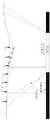
步骤S3025、基于多组形变剖面图得到预测模型,所述预测模型用于确定超前影响角变化情况、垂向位移变化情况、以及预测内部变形边界移动趋势;在实际回采中的各个因素变化情况如图3和图4所示,图4中的W1、W2、W3、W4均为沉降盆地下沉曲线,而通过预测模型可以准确的得到上述结果。In step S3025, a prediction model is obtained based on multiple sets of deformation profiles, and the prediction model is used to determine the change of the leading influence angle, the change of the vertical displacement, and the movement trend of the predicted internal deformation boundary; the change of each factor in the actual mining is as follows: As shown in Fig. 3 and Fig. 4, W1 , W2 , W3 and W4 in Fig. 4 are all the subsidence curves of the subsidence basin, and the above results can be obtained accurately by the prediction model.
通过该预测内部变形边界移动趋势和工作面回采工艺(采高、采速、日回采进度)构建多因素信息熵分析系统,能够指导回采过程。例如:基于预测内部边界移动趋势确定位于当前预测沉降区地面上有建筑时,可暂停施工,或者调整采高、采速、日回采进度,以防止建筑忽然坍塌。The multi-factor information entropy analysis system is constructed by predicting the movement trend of the internal deformation boundary and the working face mining process (mining height, mining speed, and daily mining progress), which can guide the mining process. For example, when it is determined that there is a building on the ground in the current predicted settlement area based on the predicted movement trend of the internal boundary, the construction can be suspended, or the mining height, mining speed, and daily mining progress can be adjusted to prevent the building from collapsing suddenly.
步骤S3026、根据所有的空间位置数据对所述预测模型进行比对,获得校正参数,得到精确的模型,对预测沉降盆地变形和发育情况进行精确评价。Step S3026 , compare the prediction models according to all the spatial position data, obtain correction parameters, obtain an accurate model, and accurately evaluate the deformation and development of the predicted subsidence basin.
需要说明的是,在煤层开采过程中,由于地层会发生沉降变形,其变形由下至上发育,因此,步骤S3024-步骤S3026是依次进行的,即,初始阶段,仅有地层内部发生变形,那么数据分析系统获得预测模型;而随着变形的逐渐扩大,后期地表也会发生变形,此时数据分析系统即可获取实际变形情况,以此对预测模型进行校正。It should be noted that in the process of coal seam mining, since the stratum will undergo subsidence and deformation, the deformation develops from bottom to top, therefore, steps S3024 to S3026 are performed in sequence, that is, in the initial stage, only the deformation occurs inside the stratum, then The data analysis system obtains the prediction model; and with the gradual expansion of the deformation, the surface will also deform in the later stage, and the data analysis system can obtain the actual deformation at this time, so as to correct the prediction model.
本发明实施例提供的工作面井地联合测试地面沉降盆地的精确评价方法,能够定量评价塌陷区地层内部变形移动与地面空间关系,掌握煤层上覆地层采煤过程中地面沉陷变形的传递机理,建立地面与钻孔数据时空关系,准确分析地面沉降盆地各项参数及其环境影响要素。发明内容在地面沉降盆地评价方法上响应快,准确性好,可以形成全过程、立体空间的动态数据采集。基于该数据,能够为采煤沉陷地层治理和恢复提供科学、可靠的治理时机和技术方法选择,还能够通过对单一工作面开采,推广全面治理矿区采煤沉陷损毁程度的评价,为实现采煤与土地保护协调发展,提供技术支撑。The precise evaluation method for the joint testing of ground subsidence basins in the working face and well ground provided by the embodiment of the present invention can quantitatively evaluate the relationship between the deformation and movement of the stratum inside the subsidence area and the ground space, and grasp the transmission mechanism of the ground subsidence deformation in the coal mining process of the overlying stratum of the coal seam. Establish the spatiotemporal relationship between ground and borehole data, and accurately analyze various parameters of the ground subsidence basin and its environmental impact factors. SUMMARY OF THE INVENTION The method for evaluating land subsidence basins has fast response and good accuracy, and can form dynamic data collection of the whole process and three-dimensional space. Based on this data, it can provide scientific and reliable treatment timing and technical method selection for the treatment and restoration of coal mining subsidence strata. It can also promote the comprehensive management of the evaluation of coal mining subsidence damage in the mining area through the mining of a single working face, so as to realize the realization of coal mining. Coordinate development with land protection and provide technical support.
另外,本发明实施例还提供了一种工作面井地联合测试地面沉降盆地的精确评价系统,所述地面沉降盆地位于地面上,所述系统包括:分布式测试系统、数据采集系统、以及与所述数据采集系统连接的数据分析系统;In addition, an embodiment of the present invention also provides an accurate evaluation system for joint testing of a ground subsidence basin on a working face, well and ground, where the ground subsidence basin is located on the ground, and the system includes: a distributed testing system, a data acquisition system, and a a data analysis system connected to the data acquisition system;
其中,所述分布式测试系统包括:与工作面走向中心线平行的地面测线、分别位于预测-10mm沉降线内部和外部的第一竖向钻孔和第二竖向钻孔,所述地面测线投影与所述工作面走向中心线在同一竖直平面内;Wherein, the distributed testing system includes: a ground survey line parallel to the working face centerline, a first vertical borehole and a second vertical borehole located inside and outside the predicted -10mm settlement line, respectively. The projection of the survey line is in the same vertical plane as the center line of the working face;
所述数据采集系统包括:若干沉降监测装置、激光测试装置和地面钻孔数据采集装置,若干所述沉降监测装置设置在位于预测-10mm沉降线内部的地面测线上,所述激光测试装置设置在所述预测-10mm沉降线外侧;所述激光测试装置获取预测沉降盆地地表每一个沉降监测装置的空间位置数据,所述地面钻孔数据采集装置获取地层内部变形数据;The data acquisition system includes: several subsidence monitoring devices, laser testing devices and ground drilling data acquisition devices, a plurality of the subsidence monitoring devices are arranged on the ground survey line located inside the predicted-10mm subsidence line, and the laser testing devices are arranged Outside the predicted-10mm subsidence line; the laser testing device obtains the spatial position data of each subsidence monitoring device on the surface of the predicted subsidence basin, and the ground drilling data acquisition device obtains the internal deformation data of the stratum;
所述数据分析系统根据已有地质资料、由激光测试装置在不同监测时刻发送的多组位移变化数据、地面钻孔数据采集装置在不同监测时刻发送的多组地层内部变形数据,以及输入的工作面回采位置数据对预测沉降盆地变形和发育情况进行评价。The data analysis system is based on the existing geological data, multiple sets of displacement change data sent by the laser testing device at different monitoring times, multiple sets of formation internal deformation data sent by the ground borehole data acquisition device at different monitoring times, and the input work. The surface mining location data are used to evaluate the deformation and development of the predicted subsidence basin.
最后应说明的是:以上实施例仅用以说明本发明的技术方案,而非对其限制;尽管参照前述实施例对本发明进行了详细的说明,本领域的普通技术人员应当理解:其依然可以对前述实施例所记载的技术方案进行修改,或者对其中部分技术特征进行等同替换;而这些修改或者替换,并不使相应技术方案的本质脱离本发明实施例技术方案的精神和范围。Finally, it should be noted that the above embodiments are only used to illustrate the technical solutions of the present invention, but not to limit them; although the present invention has been described in detail with reference to the foregoing embodiments, those of ordinary skill in the art should understand that it can still be The technical solutions described in the foregoing embodiments are modified, or some technical features thereof are equivalently replaced; and these modifications or replacements do not make the essence of the corresponding technical solutions deviate from the spirit and scope of the technical solutions in the embodiments of the present invention.
Claims (9)
Priority Applications (1)
| Application Number | Priority Date | Filing Date | Title |
|---|---|---|---|
| CN202111532797.6ACN114370852B (en) | 2021-12-15 | 2021-12-15 | Accurate evaluation method and system for working face well-ground joint test ground subsidence basin |
Applications Claiming Priority (1)
| Application Number | Priority Date | Filing Date | Title |
|---|---|---|---|
| CN202111532797.6ACN114370852B (en) | 2021-12-15 | 2021-12-15 | Accurate evaluation method and system for working face well-ground joint test ground subsidence basin |
Publications (2)
| Publication Number | Publication Date |
|---|---|
| CN114370852Atrue CN114370852A (en) | 2022-04-19 |
| CN114370852B CN114370852B (en) | 2024-03-05 |
Family
ID=81139459
Family Applications (1)
| Application Number | Title | Priority Date | Filing Date |
|---|---|---|---|
| CN202111532797.6AActiveCN114370852B (en) | 2021-12-15 | 2021-12-15 | Accurate evaluation method and system for working face well-ground joint test ground subsidence basin |
Country Status (1)
| Country | Link |
|---|---|
| CN (1) | CN114370852B (en) |
Cited By (1)
| Publication number | Priority date | Publication date | Assignee | Title |
|---|---|---|---|---|
| CN115014230A (en)* | 2022-06-24 | 2022-09-06 | 北京无线电测量研究所 | Method and system for measuring deformation of two-dimensional plane structure |
Citations (18)
| Publication number | Priority date | Publication date | Assignee | Title |
|---|---|---|---|---|
| US20050231710A1 (en)* | 2004-04-15 | 2005-10-20 | Jamieson James R | Combined laser altimeter and ground velocity measurement apparatus |
| JP2006258613A (en)* | 2005-03-17 | 2006-09-28 | National Institute Of Occupation Safety & Health Japan | Displacement measurement and displacement detection system using laser light and optical sensor. |
| JP2011102786A (en)* | 2009-11-10 | 2011-05-26 | Advanced Technology:Kk | Optical fiber settlement gauge |
| CN202947731U (en)* | 2011-12-23 | 2013-05-22 | 同方威视技术股份有限公司 | Settlement information acquisition system |
| CN106772678A (en)* | 2016-12-16 | 2017-05-31 | 安徽理工大学 | A kind of wellhole many reference amounts method for surveying of rock deformation destructive characteristics |
| CN107165676A (en)* | 2017-06-26 | 2017-09-15 | 中国矿业大学 | The Trinity monitoring method of CONTROL OF STRATA MOVEMENT |
| CN107367231A (en)* | 2017-07-11 | 2017-11-21 | 中国矿业大学 | Coal mine work area wall caving monitoring system based on fiber grating and 3 D laser scanning |
| CN107387166A (en)* | 2017-08-01 | 2017-11-24 | 安徽理工大学 | Stope coal seam plate destructing depth real-time system for monitoring and pre-warning and method |
| CN107702689A (en)* | 2017-10-11 | 2018-02-16 | 北京国华恒源科技开发有限公司 | The monitoring system and monitoring method of a kind of surface subsidence monitoring |
| CN108827233A (en)* | 2018-09-17 | 2018-11-16 | 中国地质大学(北京) | A kind of prediction technique of two layers of goaf surface subsidence |
| CN109029347A (en)* | 2018-09-05 | 2018-12-18 | 上海华测导航技术股份有限公司 | The measuring system and method for landslide displacement sedimentation based on Beidou Automatic monitoring systems |
| CN109099948A (en)* | 2018-08-08 | 2018-12-28 | 太原理工大学 | Distributed optical fiber geological subsidence and pipeline stress hazard early warning monitoring device and method |
| CN109520471A (en)* | 2018-12-12 | 2019-03-26 | 石家庄铁道大学 | Optical fiber single hole deep soil settlement survey device and its monitoring method |
| CN111382504A (en)* | 2020-02-28 | 2020-07-07 | 中国矿业大学 | Coal seam mining overburden settlement state identification method |
| CN111678454A (en)* | 2020-06-24 | 2020-09-18 | 安徽理工大学 | A distributed monitoring system and method for coal pillar stability |
| CN111895977A (en)* | 2020-09-21 | 2020-11-06 | 安徽理工大学 | Mining-movement-movement of near-horizontal coal seam-overlying rock-surface data collection method for true 3D similar material simulation |
| US20210124021A1 (en)* | 2019-10-25 | 2021-04-29 | Topcon Corporation | Laser scanner |
| CN113137951A (en)* | 2021-05-19 | 2021-07-20 | 中国地质大学(武汉) | Ground settlement monitoring device and implementation method thereof |
- 2021
- 2021-12-15CNCN202111532797.6Apatent/CN114370852B/enactiveActive
Patent Citations (18)
| Publication number | Priority date | Publication date | Assignee | Title |
|---|---|---|---|---|
| US20050231710A1 (en)* | 2004-04-15 | 2005-10-20 | Jamieson James R | Combined laser altimeter and ground velocity measurement apparatus |
| JP2006258613A (en)* | 2005-03-17 | 2006-09-28 | National Institute Of Occupation Safety & Health Japan | Displacement measurement and displacement detection system using laser light and optical sensor. |
| JP2011102786A (en)* | 2009-11-10 | 2011-05-26 | Advanced Technology:Kk | Optical fiber settlement gauge |
| CN202947731U (en)* | 2011-12-23 | 2013-05-22 | 同方威视技术股份有限公司 | Settlement information acquisition system |
| CN106772678A (en)* | 2016-12-16 | 2017-05-31 | 安徽理工大学 | A kind of wellhole many reference amounts method for surveying of rock deformation destructive characteristics |
| CN107165676A (en)* | 2017-06-26 | 2017-09-15 | 中国矿业大学 | The Trinity monitoring method of CONTROL OF STRATA MOVEMENT |
| CN107367231A (en)* | 2017-07-11 | 2017-11-21 | 中国矿业大学 | Coal mine work area wall caving monitoring system based on fiber grating and 3 D laser scanning |
| CN107387166A (en)* | 2017-08-01 | 2017-11-24 | 安徽理工大学 | Stope coal seam plate destructing depth real-time system for monitoring and pre-warning and method |
| CN107702689A (en)* | 2017-10-11 | 2018-02-16 | 北京国华恒源科技开发有限公司 | The monitoring system and monitoring method of a kind of surface subsidence monitoring |
| CN109099948A (en)* | 2018-08-08 | 2018-12-28 | 太原理工大学 | Distributed optical fiber geological subsidence and pipeline stress hazard early warning monitoring device and method |
| CN109029347A (en)* | 2018-09-05 | 2018-12-18 | 上海华测导航技术股份有限公司 | The measuring system and method for landslide displacement sedimentation based on Beidou Automatic monitoring systems |
| CN108827233A (en)* | 2018-09-17 | 2018-11-16 | 中国地质大学(北京) | A kind of prediction technique of two layers of goaf surface subsidence |
| CN109520471A (en)* | 2018-12-12 | 2019-03-26 | 石家庄铁道大学 | Optical fiber single hole deep soil settlement survey device and its monitoring method |
| US20210124021A1 (en)* | 2019-10-25 | 2021-04-29 | Topcon Corporation | Laser scanner |
| CN111382504A (en)* | 2020-02-28 | 2020-07-07 | 中国矿业大学 | Coal seam mining overburden settlement state identification method |
| CN111678454A (en)* | 2020-06-24 | 2020-09-18 | 安徽理工大学 | A distributed monitoring system and method for coal pillar stability |
| CN111895977A (en)* | 2020-09-21 | 2020-11-06 | 安徽理工大学 | Mining-movement-movement of near-horizontal coal seam-overlying rock-surface data collection method for true 3D similar material simulation |
| CN113137951A (en)* | 2021-05-19 | 2021-07-20 | 中国地质大学(武汉) | Ground settlement monitoring device and implementation method thereof |
Non-Patent Citations (3)
| Title |
|---|
| 李旭娟: "东滩煤矿西风井地层沉降光纤Bragg光栅监测研究", 《中国优秀硕士学位论文全文数据库工程科技Ⅰ辑 》, no. 04, pages 021 - 69* |
| 潘健: "大红山铁矿地表塌陷规律研究", 《中国优秀硕士学位论文全文数据库工程科技Ⅰ辑》, no. 05, pages 021 - 59* |
| 贡彬: "分布式光纤传感器在煤矿顶板中的应变监测研究", 《中国优秀硕士学位论文全文数据库工程科技Ⅰ辑》, no. 01, pages 021 - 410* |
Cited By (1)
| Publication number | Priority date | Publication date | Assignee | Title |
|---|---|---|---|---|
| CN115014230A (en)* | 2022-06-24 | 2022-09-06 | 北京无线电测量研究所 | Method and system for measuring deformation of two-dimensional plane structure |
Also Published As
| Publication number | Publication date |
|---|---|
| CN114370852B (en) | 2024-03-05 |
Similar Documents
| Publication | Publication Date | Title |
|---|---|---|
| CN104454010B (en) | A kind of deep-well tunnel tunneling construction dynamic comprehensive monitor and early warning system and method for early warning | |
| CN102736124B (en) | Tunnel excavation surrounding rock dynamic refined classification method based on integrated parameters | |
| CN101892830B (en) | Deep ground stress measurement while drilling (MWD) system | |
| WO2021227236A1 (en) | Multi-wavefield seismic detection method and system employing construction noise of shield tunneling machine | |
| CN102995615B (en) | A kind of method of real-time for underground deep layer land movement | |
| CN105134194B (en) | A kind of device and measuring method that crustal stress is measured by one borehole | |
| CN111999781A (en) | A dynamic measurement and analysis method for all-round surrounding rock structure of deep well roadway | |
| CN206016797U (en) | Measurement module and the mine with the measurement module are with brill deviational survey exploration system | |
| CN113551637B (en) | Monitoring device and method for surrounding rock deformation in the whole process of tunnel construction based on TBM | |
| CN101629799A (en) | Non-intervisibility high and steep side slope deformation monitoring method and device thereof | |
| CN106959095A (en) | Geology internal displacement three-dimension monitor system and its Embedded installation method, measuring method | |
| CN106556376B (en) | Device for monitoring deformation of underground space and underground pipeline and measuring method thereof | |
| CN115788579A (en) | Method for monitoring spatial and temporal evolution of three zones of overlying strata during coal seam mining | |
| CN108343432A (en) | A kind of drilling pouring pile hole quality detection device and its detection method | |
| CN116128290A (en) | Intelligent evaluation digital twin system for urban built-up area shield method construction environment risk | |
| CN109781056A (en) | Deformation measurement data methods of exhibiting and storage medium based on internal displacement | |
| US20230140874A1 (en) | Method for monitoring hydraulic fracturing range of surface vertical shaft | |
| CN206862331U (en) | Geology internal displacement three-dimension monitor system | |
| CN114370852A (en) | Accurate evaluation method and system for working face well-ground combined test ground subsidence basin | |
| CN107101624B (en) | Geological deformation three-dimensional observation system and its installation and burial methods and measurement methods | |
| CN114991193A (en) | Pile foundation construction method for collapsible loess area by rotary drilling dry excavation method | |
| CN203021982U (en) | Underground deep soil displacement real-time monitor system | |
| CN202850007U (en) | Shallow stratum multipoint settlement real-time monitoring device | |
| CN207277308U (en) | Bridge construction of pile groups monitors system to the soil disturbance of adjacent piles | |
| CN206917622U (en) | A kind of derrick well head measures centralising device |
Legal Events
| Date | Code | Title | Description |
|---|---|---|---|
| PB01 | Publication | ||
| PB01 | Publication | ||
| SE01 | Entry into force of request for substantive examination | ||
| SE01 | Entry into force of request for substantive examination | ||
| GR01 | Patent grant | ||
| GR01 | Patent grant |