CN114369933A - Clip for airing - Google Patents
Clip for airingDownload PDFInfo
- Publication number
- CN114369933A CN114369933ACN202210063841.1ACN202210063841ACN114369933ACN 114369933 ACN114369933 ACN 114369933ACN 202210063841 ACN202210063841 ACN 202210063841ACN 114369933 ACN114369933 ACN 114369933A
- Authority
- CN
- China
- Prior art keywords
- lock
- arm
- clamp body
- clip
- drying
- Prior art date
- Legal status (The legal status is an assumption and is not a legal conclusion. Google has not performed a legal analysis and makes no representation as to the accuracy of the status listed.)
- Pending
Links
Images

Classifications
- D—TEXTILES; PAPER
- D06—TREATMENT OF TEXTILES OR THE LIKE; LAUNDERING; FLEXIBLE MATERIALS NOT OTHERWISE PROVIDED FOR
- D06F—LAUNDERING, DRYING, IRONING, PRESSING OR FOLDING TEXTILE ARTICLES
- D06F55/00—Clothes-pegs
Landscapes
- Engineering & Computer Science (AREA)
- Textile Engineering (AREA)
- Holders For Apparel And Elements Relating To Apparel (AREA)
Abstract
Translated fromChinese
Description
Translated fromChinese技术领域technical field
本发明涉及一种夹子,尤其涉及一种晾晒用夹,属于日常用品技术领域。The invention relates to a clip, in particular to a clip for drying, belonging to the technical field of daily necessities.
背景技术Background technique
夹子是日常用品,其种类也很多,比如发夹、文件夹、衣服夹等。而用于晾晒的主要是衣服夹,现有的衣服夹都是由两个半夹体和一根扭簧组合而成。生活中,我们都会有过这种经历,发明人在小区晾晒杆上晾晒被子、床单等较大物件时,需要搭在晾晒杆上,而晾晒杆是不锈钢的空心管,尺寸较大,现有的衣服夹只能在物件对折搭下来后,夹在对折的物件边的两个边上。这样,存在以下问题,一是晾晒速度慢,二是在有风的情况下,床单等较大物件的边会产生波浪形扭动而使得夹子脱落,最后床单等物件被吹落地上而导致脏了。Clips are daily necessities, and there are many types, such as hairpins, folders, clothespins and so on. The clothes clips are mainly used for drying, and the existing clothes clips are composed of two half-clamp bodies and a torsion spring. In our daily life, we all have this experience. When the inventor is drying larger objects such as quilts and bed sheets on the drying rod in the community, he needs to hang it on the drying rod, and the drying rod is a hollow stainless steel tube with a large size. The clothes clips can only be clipped on the two sides of the folded object after the object is folded in half. In this way, there are the following problems, one is that the drying speed is slow, and the other is that in the case of wind, the edges of large objects such as sheets will twist in a wavy shape, causing the clips to fall off, and finally the sheets and other objects will be blown to the ground. .
发明人就这些问题,查找了当下市场,没有价格合理,适用于晾晒用的夹子。In view of these problems, the inventor has searched the current market, and there is no clip with reasonable price that is suitable for drying.
发明内容SUMMARY OF THE INVENTION
发明人通过研究,给出了一种结构简单,易于制作,价格合理,适用于晾晒用的夹子。Through research, the inventor provides a clip with simple structure, easy manufacture and reasonable price, which is suitable for drying.
为达到上述目的,本发明所采用的技术手段是:一种晾晒用夹,包括固定框、上夹体、下夹体和滑锁机构,滑锁机构、上夹体和下夹体通过固定框安装,所述滑锁机构连接上夹体和下夹体,在滑锁机构运动时,上夹体和下夹体跟随运动,滑锁机构锁定时,上夹体和下夹体被锁定;在晾晒时,上夹体和下夹体卡接在晾晒物外部并包向晾晒杆,通过滑锁机构运动将上夹体和下夹体逐渐靠近,而后锁定,形成夹持状态,晾晒结束时,滑锁机构打开锁定,通过滑锁机构运动将上夹体和下夹体打开。In order to achieve the above purpose, the technical means adopted in the present invention are: a drying clip, comprising a fixing frame, an upper clip body, a lower clip body and a sliding lock mechanism, and the sliding lock mechanism, the upper clip body and the lower clip body pass through the fixing frame. installation, the sliding lock mechanism connects the upper clamping body and the lower clamping body, when the sliding locking mechanism moves, the upper clamping body and the lower clamping body follow the movement, and when the sliding locking mechanism is locked, the upper clamping body and the lower clamping body are locked; When drying, the upper clip body and the lower clip body are clamped to the outside of the drying object and wrapped around the drying rod, and the upper clip body and the lower clip body are gradually approached by the movement of the sliding lock mechanism, and then locked to form a clamping state. The sliding lock mechanism opens and locks, and the upper clamping body and the lower clamping body are opened through the movement of the sliding lock mechanism.
进一步的,所述固定框至少具有两个侧板和一个顶板、一个底板,顶板安装在两块侧板的顶部,底板安装在两块侧板的底部。Further, the fixing frame has at least two side panels, a top panel, and a bottom panel, the top panel is mounted on the top of the two side panels, and the bottom panel is mounted on the bottom of the two side panels.
更进一步的,所述下夹体为一个弧形的下夹臂,在下夹臂一侧的弧形外壁上设置若干齿牙;所述上夹体包括一个上夹臂,在上夹臂对应下夹臂齿牙一侧开通槽,在通槽上方设置弧形齿臂,齿臂的两端通过两个连接边与通槽两端连接,在弧形齿臂的内表面上设置若干齿牙;滑锁机构具有一根齿杆,齿杆上的齿分别与弧形齿臂和下夹臂上的齿牙啮合,齿杆的齿杆轴分别安装在两块侧板上,在固定框上设置锁结构。Further, the lower clip body is an arc-shaped lower clip arm, and a number of teeth are arranged on the arc-shaped outer wall on one side of the lower clip arm; the upper clip body includes an upper clip arm, and the upper clip arm corresponds to the lower clip arm. A slot is opened on one side of the teeth of the clamping arm, an arc-shaped toothed arm is arranged above the through slot, the two ends of the toothed arm are connected with both ends of the through slot through two connecting edges, and a number of teeth are arranged on the inner surface of the arc-shaped toothed arm; The sliding lock mechanism has a toothed rod, the teeth on the toothed rod mesh with the teeth on the arc-shaped toothed arm and the lower clamping arm respectively. lock structure.
更进一步的,所述锁结构为锁柱和设置在齿杆端面的锁孔,通过锁柱插入锁孔实现锁定,锁柱拉出锁孔解锁。Further, the lock structure is a lock column and a lock hole arranged on the end face of the toothed rod. The lock column is inserted into the lock hole to achieve locking, and the lock column is pulled out of the lock hole to unlock.
更进一步的,所述底板为弧形且在底板的内表面两侧分别设置一个具有容纳上夹臂和下夹臂两边的滑槽。Furthermore, the bottom plate is arc-shaped, and two sides of the inner surface of the bottom plate are respectively provided with a chute having two sides for accommodating the upper clamping arm and the lower clamping arm.
更进一步的,所述锁结构为锁杆或锁板,在固定框的两个侧板上均设置滑槽,在两个滑槽内设置锁杆或锁板,通过锁杆或锁板压紧。Further, the lock structure is a lock rod or a lock plate, and two side plates of the fixing frame are provided with a chute, a lock rod or a lock plate is arranged in the two chute, and the lock rod or the lock plate is pressed by the lock rod or the lock plate. .
更进一步的,所述上夹臂、下夹臂的悬空端部设置一个夹脚。Further, a clip foot is provided on the suspended ends of the upper clip arm and the lower clip arm.
本发明的有益效果在于:结构简单,易于制作,成本低,适宜大众购买使用;以滑锁机构调节上夹体和下夹体,实现夹紧和放开,操作简单,特别适合晾晒杆上晾晒大型衣物用品。The beneficial effects of the invention are as follows: the structure is simple, easy to manufacture, and the cost is low, which is suitable for the public to buy and use; the sliding lock mechanism is used to adjust the upper clamping body and the lower clamping body to realize clamping and releasing, and the operation is simple, and is especially suitable for drying on a drying rod. Large clothing items.
附图说明Description of drawings
下面结合附图和实施例对本发明做进一步的阐述。The present invention will be further elaborated below in conjunction with the accompanying drawings and embodiments.
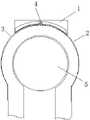
图1 为本发明的结构示意图;Fig. 1 is the structural schematic diagram of the present invention;
图2为本发明的使用结合结构示意图;2 is a schematic diagram of a combined structure of the present invention;
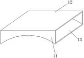
图3 为本发明的固定框结构示意图。FIG. 3 is a schematic structural diagram of the fixing frame of the present invention.
图中:1、固定框,11、侧板,12、顶板,13、底板,2、上夹体,3、下夹体,4、滑锁机构,5、晾晒杆。In the figure: 1. Fixed frame, 11, Side plate, 12, Top plate, 13, Bottom plate, 2. Upper clip body, 3, Lower clip body, 4. Slide lock mechanism, 5. Drying rod.
具体实施方式Detailed ways
实施例1Example 1
如图1、2所示的一种晾晒用夹,包括固定框1、上夹体2、下夹体3和滑锁机构4,滑锁机构4、上夹体2和下夹体3通过固定框1安装,所述滑锁机构4连接上夹体2和下夹体3,在滑锁机构4运动时,上夹体2和下夹体3跟随运动,滑锁机构4锁定时,上夹体2和下夹体3被锁定;在晾晒时,上夹体2和下夹体3卡接在晾晒物外部并包向晾晒杆5,通过滑锁机构4运动将上夹体2和下夹体3逐渐靠近,而后锁定,形成夹持状态,晾晒结束时,滑锁机构4打开锁定,通过滑锁机构4运动将上夹体2和下夹体3打开。As shown in Figures 1 and 2, a drying clip includes a
作为具体设计,所述下夹体2为一个弧形的下夹臂,在下夹臂一侧的弧形外壁上设置若干齿牙;所述上夹体3包括一个上夹臂,在上夹臂对应下夹臂齿牙一侧开通槽,在通槽上方设置弧形齿臂,齿臂的两端通过两个连接边与通槽两端连接,在弧形齿臂的内表面上设置若干齿牙;滑锁机构4具有一根齿杆,齿杆上的齿分别与弧形齿臂和下夹臂上的齿牙啮合,齿杆的齿杆轴分别安装在两块侧板上,在固定框上设置锁结构。As a specific design, the
如图3所示,所述固定框1至少具有两个侧板11和一个顶板12、一个底板13,顶板12安装在两块侧板11的顶部,底板12安装在两块侧板11的底部。As shown in FIG. 3 , the
实施例2Example 2
作为对实施例1的具体设计,所述锁结构为锁柱和设置在齿杆端面的锁孔,通过锁柱插入锁孔实现锁定,锁柱拉出锁孔解锁。As a specific design for
所述底板12为弧形且在底板的内表面两侧分别设置一个具有容纳上夹臂和下夹臂两边的滑槽。该结构设计用于限定上夹臂和下夹臂沿轨道滑动,使得运动更准确,操作更顺畅。The
所述上夹臂、下夹臂的悬空端部设置一个夹脚。A clip foot is provided on the suspended ends of the upper clip arm and the lower clip arm.
实施例3Example 3
作为对实施例1的具体设计,所述锁结构为锁杆或锁板,在固定框的两个侧板上均设置滑槽,在两个滑槽内设置锁杆或锁板,通过锁杆或锁板压紧。As a specific design for
作为锁结构,现有技术中具有很多,本发明在实施例中列举了两个,但是,以现有技术直接的替换都是可行的,关键在于方便操作和价格低廉。There are many lock structures in the prior art, two of which are listed in the embodiments of the present invention. However, direct replacement with the prior art is feasible, and the key lies in convenient operation and low price.
本发明结构简单,易于制作,成本低,适宜大众购买使用;以滑锁机构调节上夹体和下夹体,实现夹紧和放开,操作简单,特别适合晾晒杆上晾晒大型衣物用品。The invention is simple in structure, easy to manufacture, low in cost, and suitable for the public to buy and use; the upper and lower clamping bodies are adjusted by the sliding lock mechanism to realize clamping and releasing, and the operation is simple, and is especially suitable for drying large clothes on a drying rod.
尽管上文对本发明的具体实施方式给予了详细描述和说明,但是应该指明的是,我们可以依据本发明的构想对上述实施方式进行各种等效改变和修改,其所产生的功能作用仍未超出说明书所涵盖的精神时,均应在本发明的保护范围之内。Although the specific embodiments of the present invention have been described and illustrated in detail above, it should be pointed out that various equivalent changes and modifications can be made to the above-mentioned embodiments according to the concept of the present invention, and the resulting functional effects are still not available. Anything beyond the spirit covered by the description should fall within the protection scope of the present invention.
Claims (7)
Priority Applications (1)
| Application Number | Priority Date | Filing Date | Title |
|---|---|---|---|
| CN202210063841.1ACN114369933A (en) | 2022-01-20 | 2022-01-20 | Clip for airing |
Applications Claiming Priority (1)
| Application Number | Priority Date | Filing Date | Title |
|---|---|---|---|
| CN202210063841.1ACN114369933A (en) | 2022-01-20 | 2022-01-20 | Clip for airing |
Publications (1)
| Publication Number | Publication Date |
|---|---|
| CN114369933Atrue CN114369933A (en) | 2022-04-19 |
Family
ID=81145049
Family Applications (1)
| Application Number | Title | Priority Date | Filing Date |
|---|---|---|---|
| CN202210063841.1APendingCN114369933A (en) | 2022-01-20 | 2022-01-20 | Clip for airing |
Country Status (1)
| Country | Link |
|---|---|
| CN (1) | CN114369933A (en) |
Citations (31)
| Publication number | Priority date | Publication date | Assignee | Title |
|---|---|---|---|---|
| WO1998018991A1 (en)* | 1996-10-29 | 1998-05-07 | Christoph Heiland | Clamping device and production process |
| JP2006102021A (en)* | 2004-10-04 | 2006-04-20 | Kenji Tanaka | Clothespin |
| TWM298600U (en)* | 2006-02-27 | 2006-10-01 | Far East College | Improved structure of clothespin set |
| CN101664262A (en)* | 2009-10-12 | 2010-03-10 | 吴良桂 | Hanger of clothes rack |
| JP2011250968A (en)* | 2010-06-02 | 2011-12-15 | Hiroshi Ishizaka | Laundry pole pinch |
| CN102782204A (en)* | 2009-12-18 | 2012-11-14 | 刘璜 | Clips & Clip Hangers |
| CN203749127U (en)* | 2014-03-14 | 2014-08-06 | 骆元郡 | Multifunctional spring windproof clothes hanger and movable clothes hanger rod thereof |
| WO2014133080A1 (en)* | 2013-02-27 | 2014-09-04 | ぺんてる株式会社 | Attachment structure for clip |
| CN104545350A (en)* | 2015-02-02 | 2015-04-29 | 陈世德 | Trousers rack |
| CN104918650A (en)* | 2013-01-03 | 2015-09-16 | 威格米德公司 | Spring clip needle guard |
| CN107720261A (en)* | 2017-09-13 | 2018-02-23 | 兔皇羊绒有限公司 | A kind of rubber strip pinch mechanism |
| CN108838885A (en)* | 2018-06-26 | 2018-11-20 | 芜湖虹点帮网络科技有限公司 | A kind of hardware polishing machine clamping device improving stability |
| CN208183366U (en)* | 2018-04-02 | 2018-12-04 | 浙江师范大学 | A kind of shift fork locking type radix saposhnikoviae is shone by clip |
| CN108993635A (en)* | 2018-08-22 | 2018-12-14 | 梁才 | A kind of medical inspection test tube clamper |
| CN208337652U (en)* | 2018-07-13 | 2019-01-04 | 深圳市法码尔科技开发有限公司 | Electronic clamp bracket |
| KR20190046476A (en)* | 2017-10-26 | 2019-05-07 | 김래균 | Hanger for pipe |
| CN209485221U (en)* | 2018-12-28 | 2019-10-11 | 天津泰美科科技有限公司 | A kind of crankshaft external diameter detection device |
| US10531755B1 (en)* | 2018-12-27 | 2020-01-14 | Pei-Hsiu Huang | Drink holder mounting structure for attaching to various tubular objects |
| CN111411491A (en)* | 2020-05-07 | 2020-07-14 | 广东好太太科技集团股份有限公司 | Airing clip |
| CN211305810U (en)* | 2019-12-20 | 2020-08-21 | 天津市万基钢管有限公司 | Steel pipe off-line inner burr grinding machine |
| CN211689236U (en)* | 2020-03-14 | 2020-10-16 | 舟山振航船舶修造服务有限公司 | Laser cladding clamp for repairing gear |
| CN111997441A (en)* | 2020-09-14 | 2020-11-27 | 雷关东 | Rack-driven multi-coding anti-theft lock cylinder |
| CN212367263U (en)* | 2020-06-29 | 2021-01-15 | 德清创赢机械科技有限公司 | Can with fixed handheld intercom of arm |
| CN112454569A (en)* | 2020-11-06 | 2021-03-09 | 常宁市常鑫竹筷厂 | Chopsticks processing is with bamboo burst device |
| CN213681377U (en)* | 2020-11-06 | 2021-07-13 | 广东海泰金属制品有限公司 | Universal clothes rod clamp |
| CN213873982U (en)* | 2020-10-08 | 2021-08-03 | 江苏金冠警用器材制造有限公司 | Stainless steel fork with self-locking device |
| CN214061003U (en)* | 2020-10-22 | 2021-08-27 | 无锡职业技术学院 | a drying rack |
| CN214433530U (en)* | 2021-03-31 | 2021-10-22 | 揭阳市榕城区梅云顺财不锈钢制品厂 | Slide lock multipurpose food clamp |
| CN214454956U (en)* | 2021-03-30 | 2021-10-22 | 山东轻工职业学院 | Material handling manipulator |
| CN113694361A (en)* | 2021-08-27 | 2021-11-26 | 南阳市中心医院 | Powder and liquid medicine applicator for thoracic surgery |
| CN215425185U (en)* | 2021-04-30 | 2022-01-07 | 吕启凤 | Fat clamp for eye plastic surgery |
- 2022
- 2022-01-20CNCN202210063841.1Apatent/CN114369933A/enactivePending
Patent Citations (31)
| Publication number | Priority date | Publication date | Assignee | Title |
|---|---|---|---|---|
| WO1998018991A1 (en)* | 1996-10-29 | 1998-05-07 | Christoph Heiland | Clamping device and production process |
| JP2006102021A (en)* | 2004-10-04 | 2006-04-20 | Kenji Tanaka | Clothespin |
| TWM298600U (en)* | 2006-02-27 | 2006-10-01 | Far East College | Improved structure of clothespin set |
| CN101664262A (en)* | 2009-10-12 | 2010-03-10 | 吴良桂 | Hanger of clothes rack |
| CN102782204A (en)* | 2009-12-18 | 2012-11-14 | 刘璜 | Clips & Clip Hangers |
| JP2011250968A (en)* | 2010-06-02 | 2011-12-15 | Hiroshi Ishizaka | Laundry pole pinch |
| CN104918650A (en)* | 2013-01-03 | 2015-09-16 | 威格米德公司 | Spring clip needle guard |
| WO2014133080A1 (en)* | 2013-02-27 | 2014-09-04 | ぺんてる株式会社 | Attachment structure for clip |
| CN203749127U (en)* | 2014-03-14 | 2014-08-06 | 骆元郡 | Multifunctional spring windproof clothes hanger and movable clothes hanger rod thereof |
| CN104545350A (en)* | 2015-02-02 | 2015-04-29 | 陈世德 | Trousers rack |
| CN107720261A (en)* | 2017-09-13 | 2018-02-23 | 兔皇羊绒有限公司 | A kind of rubber strip pinch mechanism |
| KR20190046476A (en)* | 2017-10-26 | 2019-05-07 | 김래균 | Hanger for pipe |
| CN208183366U (en)* | 2018-04-02 | 2018-12-04 | 浙江师范大学 | A kind of shift fork locking type radix saposhnikoviae is shone by clip |
| CN108838885A (en)* | 2018-06-26 | 2018-11-20 | 芜湖虹点帮网络科技有限公司 | A kind of hardware polishing machine clamping device improving stability |
| CN208337652U (en)* | 2018-07-13 | 2019-01-04 | 深圳市法码尔科技开发有限公司 | Electronic clamp bracket |
| CN108993635A (en)* | 2018-08-22 | 2018-12-14 | 梁才 | A kind of medical inspection test tube clamper |
| US10531755B1 (en)* | 2018-12-27 | 2020-01-14 | Pei-Hsiu Huang | Drink holder mounting structure for attaching to various tubular objects |
| CN209485221U (en)* | 2018-12-28 | 2019-10-11 | 天津泰美科科技有限公司 | A kind of crankshaft external diameter detection device |
| CN211305810U (en)* | 2019-12-20 | 2020-08-21 | 天津市万基钢管有限公司 | Steel pipe off-line inner burr grinding machine |
| CN211689236U (en)* | 2020-03-14 | 2020-10-16 | 舟山振航船舶修造服务有限公司 | Laser cladding clamp for repairing gear |
| CN111411491A (en)* | 2020-05-07 | 2020-07-14 | 广东好太太科技集团股份有限公司 | Airing clip |
| CN212367263U (en)* | 2020-06-29 | 2021-01-15 | 德清创赢机械科技有限公司 | Can with fixed handheld intercom of arm |
| CN111997441A (en)* | 2020-09-14 | 2020-11-27 | 雷关东 | Rack-driven multi-coding anti-theft lock cylinder |
| CN213873982U (en)* | 2020-10-08 | 2021-08-03 | 江苏金冠警用器材制造有限公司 | Stainless steel fork with self-locking device |
| CN214061003U (en)* | 2020-10-22 | 2021-08-27 | 无锡职业技术学院 | a drying rack |
| CN112454569A (en)* | 2020-11-06 | 2021-03-09 | 常宁市常鑫竹筷厂 | Chopsticks processing is with bamboo burst device |
| CN213681377U (en)* | 2020-11-06 | 2021-07-13 | 广东海泰金属制品有限公司 | Universal clothes rod clamp |
| CN214454956U (en)* | 2021-03-30 | 2021-10-22 | 山东轻工职业学院 | Material handling manipulator |
| CN214433530U (en)* | 2021-03-31 | 2021-10-22 | 揭阳市榕城区梅云顺财不锈钢制品厂 | Slide lock multipurpose food clamp |
| CN215425185U (en)* | 2021-04-30 | 2022-01-07 | 吕启凤 | Fat clamp for eye plastic surgery |
| CN113694361A (en)* | 2021-08-27 | 2021-11-26 | 南阳市中心医院 | Powder and liquid medicine applicator for thoracic surgery |
Non-Patent Citations (1)
| Title |
|---|
| 上海市机电设计院: "铸造车间机械化 第3篇 第8-10章 制芯机械化", vol. 1, 北京航空航天大学出版社, pages: 128 - 130* |
Similar Documents
| Publication | Publication Date | Title |
|---|---|---|
| CN114369933A (en) | Clip for airing | |
| CN218259384U (en) | A textile storage device for textiles | |
| CN103498554B (en) | A kind of split type concrete blinding | |
| CN2742886Y (en) | Expansion wind proof clothes hanger | |
| CN205513933U (en) | Multifunctional clothes hanger | |
| CN203619271U (en) | Lock latch of needle clamp | |
| CN205994213U (en) | A kind of clothes hanger | |
| CN2511200Y (en) | Seat with clothes hanger | |
| CN206371808U (en) | The double-deck telescopic clothes rack that level is pulled | |
| CN212047652U (en) | A retractable device for an intelligent single garage | |
| CN205711483U (en) | A kind of underwear disinfection drying integrated device | |
| CN203531373U (en) | Split concrete template | |
| CN110742472A (en) | A clothes hanger with a folding and shrinking function for automobiles | |
| CN220601418U (en) | Folding and recycling LED shoe box lamp arm | |
| CN201480996U (en) | Telescopic trouser rack | |
| CN211815084U (en) | Clothes placing device for clothes ironing | |
| CN2384972Y (en) | Improved telescopic clothes rail | |
| CN219430336U (en) | Towel rack with rack | |
| CN218355608U (en) | Double-layer pulley clothes hanger | |
| CN222730175U (en) | Clothes drying rack for clothes | |
| CN2633928Y (en) | Ironing board | |
| CN201356400Y (en) | Multilayered clothes rack | |
| CN215820054U (en) | A portable suitcase with convertible coffee table | |
| CN211212495U (en) | A clothes fork for easy pulling and hooking of clothes hangers | |
| CN215738287U (en) | Adjustable clothes hanger |
Legal Events
| Date | Code | Title | Description |
|---|---|---|---|
| PB01 | Publication | ||
| PB01 | Publication | ||
| SE01 | Entry into force of request for substantive examination | ||
| SE01 | Entry into force of request for substantive examination | ||
| RJ01 | Rejection of invention patent application after publication | ||
| RJ01 | Rejection of invention patent application after publication | Application publication date:20220419 |