CN114366301B - Navigation positioning system for hip replacement surgery and use method thereof - Google Patents
Navigation positioning system for hip replacement surgery and use method thereofDownload PDFInfo
- Publication number
- CN114366301B CN114366301BCN202210107945.8ACN202210107945ACN114366301BCN 114366301 BCN114366301 BCN 114366301BCN 202210107945 ACN202210107945 ACN 202210107945ACN 114366301 BCN114366301 BCN 114366301B
- Authority
- CN
- China
- Prior art keywords
- assembly
- positioning
- frame
- rotating
- calibration frame
- Prior art date
- Legal status (The legal status is an assumption and is not a legal conclusion. Google has not performed a legal analysis and makes no representation as to the accuracy of the status listed.)
- Active
Links
- 238000001356surgical procedureMethods0.000titleclaimsabstractdescription29
- 238000011540hip replacementMethods0.000titleclaimsdescription8
- 238000000034methodMethods0.000titleabstractdescription22
- 230000003287optical effectEffects0.000claimsdescription16
- 210000004394hip jointAnatomy0.000abstractdescription20
- 230000008569processEffects0.000description7
- 238000010586diagramMethods0.000description5
- 210000000588acetabulumAnatomy0.000description4
- 230000009286beneficial effectEffects0.000description4
- 238000007906compressionMethods0.000description4
- 230000006835compressionEffects0.000description4
- 238000007907direct compressionMethods0.000description3
- 238000009434installationMethods0.000description2
- 230000007774longtermEffects0.000description2
- 230000000399orthopedic effectEffects0.000description2
- 230000004044responseEffects0.000description2
- 230000009466transformationEffects0.000description2
- 230000008859changeEffects0.000description1
- 230000004048modificationEffects0.000description1
- 238000012986modificationMethods0.000description1
Images


Classifications
- A—HUMAN NECESSITIES
- A61—MEDICAL OR VETERINARY SCIENCE; HYGIENE
- A61B—DIAGNOSIS; SURGERY; IDENTIFICATION
- A61B34/00—Computer-aided surgery; Manipulators or robots specially adapted for use in surgery
- A61B34/20—Surgical navigation systems; Devices for tracking or guiding surgical instruments, e.g. for frameless stereotaxis
- A—HUMAN NECESSITIES
- A61—MEDICAL OR VETERINARY SCIENCE; HYGIENE
- A61B—DIAGNOSIS; SURGERY; IDENTIFICATION
- A61B34/00—Computer-aided surgery; Manipulators or robots specially adapted for use in surgery
- A61B34/30—Surgical robots
- A—HUMAN NECESSITIES
- A61—MEDICAL OR VETERINARY SCIENCE; HYGIENE
- A61F—FILTERS IMPLANTABLE INTO BLOOD VESSELS; PROSTHESES; DEVICES PROVIDING PATENCY TO, OR PREVENTING COLLAPSING OF, TUBULAR STRUCTURES OF THE BODY, e.g. STENTS; ORTHOPAEDIC, NURSING OR CONTRACEPTIVE DEVICES; FOMENTATION; TREATMENT OR PROTECTION OF EYES OR EARS; BANDAGES, DRESSINGS OR ABSORBENT PADS; FIRST-AID KITS
- A61F2/00—Filters implantable into blood vessels; Prostheses, i.e. artificial substitutes or replacements for parts of the body; Appliances for connecting them with the body; Devices providing patency to, or preventing collapsing of, tubular structures of the body, e.g. stents
- A61F2/02—Prostheses implantable into the body
- A61F2/30—Joints
- A61F2/46—Special tools for implanting artificial joints
- A61F2/4601—Special tools for implanting artificial joints for introducing bone substitute, for implanting bone graft implants or for compacting them in the bone cavity
- A—HUMAN NECESSITIES
- A61—MEDICAL OR VETERINARY SCIENCE; HYGIENE
- A61F—FILTERS IMPLANTABLE INTO BLOOD VESSELS; PROSTHESES; DEVICES PROVIDING PATENCY TO, OR PREVENTING COLLAPSING OF, TUBULAR STRUCTURES OF THE BODY, e.g. STENTS; ORTHOPAEDIC, NURSING OR CONTRACEPTIVE DEVICES; FOMENTATION; TREATMENT OR PROTECTION OF EYES OR EARS; BANDAGES, DRESSINGS OR ABSORBENT PADS; FIRST-AID KITS
- A61F2/00—Filters implantable into blood vessels; Prostheses, i.e. artificial substitutes or replacements for parts of the body; Appliances for connecting them with the body; Devices providing patency to, or preventing collapsing of, tubular structures of the body, e.g. stents
- A61F2/02—Prostheses implantable into the body
- A61F2/30—Joints
- A61F2/46—Special tools for implanting artificial joints
- A61F2/4603—Special tools for implanting artificial joints for insertion or extraction of endoprosthetic joints or of accessories thereof
- A61F2/4609—Special tools for implanting artificial joints for insertion or extraction of endoprosthetic joints or of accessories thereof of acetabular cups
- A—HUMAN NECESSITIES
- A61—MEDICAL OR VETERINARY SCIENCE; HYGIENE
- A61B—DIAGNOSIS; SURGERY; IDENTIFICATION
- A61B34/00—Computer-aided surgery; Manipulators or robots specially adapted for use in surgery
- A61B34/20—Surgical navigation systems; Devices for tracking or guiding surgical instruments, e.g. for frameless stereotaxis
- A61B2034/2046—Tracking techniques
- A61B2034/2055—Optical tracking systems
- A—HUMAN NECESSITIES
- A61—MEDICAL OR VETERINARY SCIENCE; HYGIENE
- A61F—FILTERS IMPLANTABLE INTO BLOOD VESSELS; PROSTHESES; DEVICES PROVIDING PATENCY TO, OR PREVENTING COLLAPSING OF, TUBULAR STRUCTURES OF THE BODY, e.g. STENTS; ORTHOPAEDIC, NURSING OR CONTRACEPTIVE DEVICES; FOMENTATION; TREATMENT OR PROTECTION OF EYES OR EARS; BANDAGES, DRESSINGS OR ABSORBENT PADS; FIRST-AID KITS
- A61F2/00—Filters implantable into blood vessels; Prostheses, i.e. artificial substitutes or replacements for parts of the body; Appliances for connecting them with the body; Devices providing patency to, or preventing collapsing of, tubular structures of the body, e.g. stents
- A61F2/02—Prostheses implantable into the body
- A61F2/30—Joints
- A61F2/46—Special tools for implanting artificial joints
- A61F2002/4681—Special tools for implanting artificial joints by applying mechanical shocks, e.g. by hammering
- A—HUMAN NECESSITIES
- A61—MEDICAL OR VETERINARY SCIENCE; HYGIENE
- A61F—FILTERS IMPLANTABLE INTO BLOOD VESSELS; PROSTHESES; DEVICES PROVIDING PATENCY TO, OR PREVENTING COLLAPSING OF, TUBULAR STRUCTURES OF THE BODY, e.g. STENTS; ORTHOPAEDIC, NURSING OR CONTRACEPTIVE DEVICES; FOMENTATION; TREATMENT OR PROTECTION OF EYES OR EARS; BANDAGES, DRESSINGS OR ABSORBENT PADS; FIRST-AID KITS
- A61F2/00—Filters implantable into blood vessels; Prostheses, i.e. artificial substitutes or replacements for parts of the body; Appliances for connecting them with the body; Devices providing patency to, or preventing collapsing of, tubular structures of the body, e.g. stents
- A61F2/02—Prostheses implantable into the body
- A61F2/30—Joints
- A61F2/46—Special tools for implanting artificial joints
- A61F2002/4687—Mechanical guides for implantation instruments
- A—HUMAN NECESSITIES
- A61—MEDICAL OR VETERINARY SCIENCE; HYGIENE
- A61F—FILTERS IMPLANTABLE INTO BLOOD VESSELS; PROSTHESES; DEVICES PROVIDING PATENCY TO, OR PREVENTING COLLAPSING OF, TUBULAR STRUCTURES OF THE BODY, e.g. STENTS; ORTHOPAEDIC, NURSING OR CONTRACEPTIVE DEVICES; FOMENTATION; TREATMENT OR PROTECTION OF EYES OR EARS; BANDAGES, DRESSINGS OR ABSORBENT PADS; FIRST-AID KITS
- A61F2/00—Filters implantable into blood vessels; Prostheses, i.e. artificial substitutes or replacements for parts of the body; Appliances for connecting them with the body; Devices providing patency to, or preventing collapsing of, tubular structures of the body, e.g. stents
- A61F2/02—Prostheses implantable into the body
- A61F2/30—Joints
- A61F2/46—Special tools for implanting artificial joints
- A61F2002/4688—Special tools for implanting artificial joints having operating or control means
- A61F2002/4696—Special tools for implanting artificial joints having operating or control means optical
Landscapes
- Health & Medical Sciences (AREA)
- Life Sciences & Earth Sciences (AREA)
- Engineering & Computer Science (AREA)
- Animal Behavior & Ethology (AREA)
- Transplantation (AREA)
- Surgery (AREA)
- Biomedical Technology (AREA)
- Heart & Thoracic Surgery (AREA)
- Orthopedic Medicine & Surgery (AREA)
- Veterinary Medicine (AREA)
- Public Health (AREA)
- General Health & Medical Sciences (AREA)
- Nuclear Medicine, Radiotherapy & Molecular Imaging (AREA)
- Molecular Biology (AREA)
- Medical Informatics (AREA)
- Physical Education & Sports Medicine (AREA)
- Robotics (AREA)
- Cardiology (AREA)
- Oral & Maxillofacial Surgery (AREA)
- Vascular Medicine (AREA)
- Surgical Instruments (AREA)
- Prostheses (AREA)
Abstract
Translated fromChinese
Description
Translated fromChinese技术领域technical field
本公开涉及定位技术领域,尤其涉及一种用于髋关节置换手术的导航定位系统及其使用方法。The present disclosure relates to the field of positioning technology, in particular to a navigation and positioning system for hip joint replacement surgery and a method for using the same.
背景技术Background technique
骨科手术机器人前端工具是用于骨科手术过程中的医疗器械,当手术人员进行髋关节置换手术过程中,需要用到直压配杆对髋臼进行锤击,使髋臼杯压配至髋关节内。The front-end tool of the orthopedic surgery robot is a medical device used in the process of orthopedic surgery. When the surgeon performs hip joint replacement surgery, it is necessary to use a direct pressure rod to hammer the acetabulum so that the acetabular cup is pressed into the hip joint. Inside.
然而,由于直压配杆长期受到击打,很容易导致直压配杆的标定架位置发生变化,并且由于医生在实际手术使用中,希望直压配杆的标定架可以沿着手柄轴旋转,以方便手术操作。However, due to the long-term impact of the direct compression rod, it is easy to cause the position of the calibration frame of the direct compression rod to change, and because the doctor hopes that the calibration frame of the direct compression rod can rotate along the handle axis in actual operation, To facilitate the operation.
但是现有技术并未提供相应的结构以及解决上述问题的方法。However, the prior art does not provide a corresponding structure and a method for solving the above problems.
公开于本申请背景技术部分的信息仅仅旨在加深对本申请的一般背景技术的理解,而不应当被视为承认或以任何形式暗示该信息构成已为本领域技术人员所公知的现有技术。The information disclosed in the background technology section of the application is only intended to deepen the understanding of the general background technology of the application, and should not be regarded as an acknowledgment or any form of suggestion that the information constitutes the prior art known to those skilled in the art.
发明内容Contents of the invention
本公开实施例提供一种用于髋关节置换手术导航定位系统及其使用方法,能够至少解决现有技术中的部分问题。Embodiments of the present disclosure provide a navigation and positioning system for hip replacement surgery and a method for using the same, which can solve at least part of the problems in the prior art.
本公开实施例的第一方面,In a first aspect of an embodiment of the present disclosure,
提供一种髋关节置换手术导航定位系统,包括:前端击打组件、标定架组件、旋转组件以及手柄组件;A navigation and positioning system for hip replacement surgery is provided, including: a front-end hitting component, a calibration frame component, a rotating component, and a handle component;
所述旋转组件分别连接所述前端击打组件、所述标定架组件以及所述手柄组件,所述旋转组件在转动时,带动所述标定架组件同步旋转,所述标定架组件为所述导航定位系统提供所述前端击打组件的坐标信息;The rotating assembly is respectively connected to the front-end hitting assembly, the calibration frame assembly and the handle assembly. When the rotation assembly rotates, it drives the calibration frame assembly to rotate synchronously. The calibration frame assembly is the navigation The positioning system provides coordinate information of the front-end striking assembly;
所述手柄组件远离所述旋转组件的一端,在受到打击力的情况下,将所承受的打击力经由所述前端击打组件传递至目标位置。The end of the handle assembly far away from the rotating assembly transmits the received striking force to the target position via the front end striking assembly when receiving an impact force.
在一种可选的实施方式中,In an alternative embodiment,
所述旋转组件包括棘轮模块、旋转定位架以及中心轴,所述棘轮模块包括棘轮,The rotating assembly includes a ratchet module, a rotating positioning frame and a central shaft, and the ratchet module includes a ratchet,
所述旋转定位架包括多个安装位置,所述棘轮与所述旋转定位架刚性连接,The rotating positioning frame includes a plurality of installation positions, the ratchet is rigidly connected with the rotating positioning frame,
所述棘轮沿着所述中心轴相对滑动。The ratchet relatively slides along the central axis.
在一种可选的实施方式中,In an alternative embodiment,
所述旋转组件还包括深沟球轴承、轴肩套、定位块、开关帽、开关定位块、轴向限位块、消隙螺母、棘轮块以及旋转定位架;The rotating assembly also includes a deep groove ball bearing, a shoulder sleeve, a positioning block, a switch cap, a switch positioning block, an axial limit block, an anti-backlash nut, a ratchet block, and a rotating positioning frame;
所述棘轮设置有滑动槽,所述滑动槽与所述棘轮块配合,用以限制中心轴旋转;The ratchet is provided with a sliding groove, and the sliding groove cooperates with the ratchet block to limit the rotation of the central shaft;
所述滑动槽沿自身圆周均匀分布,The sliding grooves are evenly distributed along their own circumference,
所述深沟球轴承安装在所述旋转定位架两端,所述深沟球轴承外圈与所述旋转定位架配合,所述深沟球轴承内圈与所述中心轴配合;The deep groove ball bearings are installed at both ends of the rotating positioning frame, the outer ring of the deep groove ball bearing cooperates with the rotating positioning frame, and the inner ring of the deep groove ball bearing cooperates with the central shaft;
所述轴肩套与右端深沟球轴承内圈配合,所述轴肩套右端依次与轴向限位块和消隙螺母配合,所述消隙螺母与中心轴螺纹配合;The shoulder sleeve cooperates with the inner ring of the deep groove ball bearing at the right end, the right end of the shoulder sleeve cooperates with the axial limit block and the anti-backlash nut in sequence, and the anti-backlash nut is threadedly engaged with the central shaft;
所述开关帽与所述定位块固定连接,所述开关定位块与轴向限位块固定连接。The switch cap is fixedly connected with the positioning block, and the switch positioning block is fixedly connected with the axial limit block.
在一种可选的实施方式中,In an alternative embodiment,
当所述开关帽被按压后,所述定位块沿所述旋转定位架移动,以使所述定位块脱离所述旋转定位架的卡槽,所述定位块与所述旋转定位架形成相对转动。When the switch cap is pressed, the positioning block moves along the rotating positioning frame, so that the positioning block breaks away from the slot of the rotating positioning frame, and the positioning block forms a relative rotation with the rotating positioning frame .
在一种可选的实施方式中,In an alternative embodiment,
所述旋转定位架与所述棘轮采用螺栓连接固定;The rotating positioning frame and the ratchet are connected and fixed by bolts;
所述深沟球轴承外圆与所述旋转定位架过盈配合。The outer circle of the deep groove ball bearing is in interference fit with the rotary positioning frame.
在一种可选的实施方式中,In an alternative embodiment,
所述旋转组件包括消隙螺母,The rotating assembly includes an anti-backlash nut,
所述消隙螺母对所述轴向限位块施加预紧力后,预紧力传递至深沟球轴承内圈;After the anti-backlash nut applies a pre-tightening force to the axial limit block, the pre-tightening force is transmitted to the inner ring of the deep groove ball bearing;
所述深沟球轴承内圈相向移动,用以消除所述深沟球轴承向游隙。The inner rings of the deep groove ball bearings move toward each other to eliminate the backlash of the deep groove ball bearings.
在一种可选的实施方式中,In an alternative embodiment,
所述标定架组件包括标定架、标定架支撑杆、反射光球柱、反射光球,The calibration frame assembly includes a calibration frame, a calibration frame support rod, a reflected light ball column, a reflected light ball,
所述标定架通过所述标定架支撑杆连接至所述旋转组件;The calibration frame is connected to the rotating assembly through the calibration frame support rod;
所述反射光球柱设置在所述标定架的两端;The reflected light ball column is arranged at both ends of the calibration frame;
所述反射光球通过所述反射光球柱安装在所述标定架上;The reflective light sphere is installed on the calibration frame through the reflective light sphere column;
所述反射光球提供坐标信息。The reflective photosphere provides coordinate information.
在一种可选的实施方式中,In an alternative embodiment,
所述前端击打组件包括中心轴和髋臼杯假体,The frontal impact assembly includes a central shaft and an acetabular cup prosthesis,
所述中心轴将经由所述手柄组件传来的力传递至所述髋臼杯假体,以将所述髋臼杯假体压配至人体髋臼内。The central shaft transmits the force transmitted through the handle assembly to the acetabular cup prosthesis, so as to press fit the acetabular cup prosthesis into the human acetabulum.
本公开实施例的第二方面,The second aspect of the embodiment of the present disclosure,
提供一种应用于如上所述的用于髋关节置换手术导航定位系统的使用方法,所述方法包括:A method for using the navigation and positioning system for hip joint replacement surgery as described above is provided, the method comprising:
将前端击打组件的髋臼杯假体置于人体髋臼窝内;Place the acetabular cup prosthesis of the front-end striking component in the human acetabular fossa;
转动旋转组件,以带动标定架组件转动;Turn the rotating assembly to drive the calibration frame assembly to rotate;
基于转动后的标定架组件的第一位置信息,确定所述前端击打组件的第二位置信息;Determining second position information of the front-end hitting component based on the first position information of the rotated calibration frame component;
在确定所述第二位置信息满足预设位置条件时,压配所述髋臼杯假体。When it is determined that the second position information satisfies a preset position condition, the acetabular cup prosthesis is press-fitted.
本公开实施例的第三方面,A third aspect of the embodiments of the present disclosure,
提供一种手术机器人系统,包括光学导航仪、光学导航仪显示器以及如前述任一项所述的髋关节置换手术导航定位系统,所述光学导航仪用于定位所述标定架组件的空间位置信息,并将所述空间位置信息传输至所述光学导航仪显示器上显示;A surgical robot system is provided, comprising an optical navigator, an optical navigator display, and a navigation and positioning system for hip joint replacement surgery as described in any one of the foregoing, the optical navigator being used to locate the spatial position information of the calibration frame assembly , and transmit the spatial position information to the display of the optical navigator for display;
基于所述空间位置信息,通过所述前端击打组件的中心轴压配髋臼杯假体。Based on the spatial position information, the acetabular cup prosthesis is press-fitted through the central axis of the front-end striking component.
本公开提供的用于髋关节置换手术的导航定位系统及其使用方法,旋转组件可旋转可停在特定角度,通过转动旋转组件,可以带动标定架组件的旋转,从而很好地解决了现有技术因为直压配杆长期受到击打,导致直压配杆的标定架位置发生变化,操作人员无法通过标定架组件为所述导航定位系统提供所述前端击打组件的坐标信息,从而导致定位不准确的问题。进一步地,实际操作人员能够根据实际需要,转动标定架实现精确定位,并且由于可转动式的结构,便于实际操作。The navigation and positioning system for hip joint replacement surgery and its application method provided by the present disclosure, the rotating assembly can rotate and stop at a specific angle, and the rotation of the rotating assembly can drive the rotation of the calibration frame assembly, thus solving the existing problems Technology Because the direct pressure distribution rod has been hit for a long time, the position of the calibration frame of the direct pressure distribution rod changes, and the operator cannot provide the coordinate information of the front-end striking component for the navigation and positioning system through the calibration frame component, resulting in positioning Inaccurate question. Furthermore, actual operators can rotate the calibration frame to achieve precise positioning according to actual needs, and the rotatable structure is convenient for actual operation.
附图说明Description of drawings
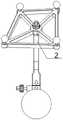
图1为本公开实施例髋关节置换手术导航定位系统的立体结构图;FIG. 1 is a three-dimensional structure diagram of a navigation and positioning system for hip joint replacement surgery according to an embodiment of the present disclosure;
图2为本公开实施例髋关节置换手术导航定位系统的主视图;FIG. 2 is a front view of a navigation and positioning system for hip joint replacement surgery according to an embodiment of the present disclosure;
图3为本公开实施例髋关节置换手术导航定位系统的俯视图;3 is a top view of the navigation and positioning system for hip joint replacement surgery according to an embodiment of the present disclosure;
图4为本公开实施例髋关节置换手术导航定位系统的左视图;Fig. 4 is a left view of the navigation and positioning system for hip joint replacement surgery according to the embodiment of the present disclosure;
图5为本公开实施例旋转组件的剖面结构示意图;5 is a schematic cross-sectional structure diagram of a rotating assembly according to an embodiment of the present disclosure;
图6为本公开实施例提供的一种手术机器人系统的结构示意图。Fig. 6 is a schematic structural diagram of a surgical robot system provided by an embodiment of the present disclosure.
其中:in:
1、前端击打组件;2、标定架组件;3、旋转组件;4、手柄组件;32、定位块;33、开关帽;34、开关帽压缩弹簧;36、消隙螺母;37、轴向限位块;38、开关定位块;39、轴肩套;40、棘轮块压缩弹簧;41、棘轮块;42、中心轴;43、锁紧帽;44、棘轮;45、深沟球轴承;46、旋转定位架;5、光学导航仪;6、光学导航仪显示器;7、髋臼。1. Front-end hitting component; 2. Calibration frame component; 3. Rotating component; 4. Handle component; 32. Positioning block; 33. Switch cap; 34. Switch cap compression spring; 36. Anti-backlash nut; 37. Axial Limiting block; 38, switch positioning block; 39, shaft shoulder sleeve; 40, ratchet block compression spring; 41, ratchet block; 42, central shaft; 43, locking cap; 44, ratchet; 45, deep groove ball bearing; 46. Rotating positioning frame; 5. Optical navigator; 6. Optical navigator display; 7. Acetabulum.
具体实施方式Detailed ways
为使本公开实施例的目的、技术方案和优点更加清楚,下面将结合本公开实施例中的附图,对本公开实施例中的技术方案进行清楚、完整地描述,显然,所描述的实施例仅仅是本公开一部分实施例,而不是全部的实施例。基于本公开中的实施例,本领域普通技术人员在没有做出创造性劳动前提下所获得的所有其他实施例,都属于本公开保护的范围。In order to make the purpose, technical solutions and advantages of the embodiments of the present disclosure clearer, the technical solutions in the embodiments of the present disclosure will be clearly and completely described below in conjunction with the drawings in the embodiments of the present disclosure. Obviously, the described embodiments It is only a part of the embodiments of the present disclosure, but not all the embodiments. Based on the embodiments in the present disclosure, all other embodiments obtained by persons of ordinary skill in the art without making creative efforts belong to the protection scope of the present disclosure.
本公开的说明书和权利要求书及上述附图中的术语“第一”、“第二”、“第三”“第四”等(如果存在)是用于区别类似的对象,而不必用于描述特定的顺序或先后次序。应该理解这样使用的数据在适当情况下可以互换,以便这里描述的本公开的实施例能够以除了在这里图示或描述的那些以外的顺序实施。The terms "first", "second", "third", "fourth", etc. (if any) in the description and claims of the present disclosure and the above drawings are used to distinguish similar objects and not necessarily Describe a specific order or sequence. It is to be understood that the data so used are interchangeable under appropriate circumstances such that the embodiments of the disclosure described herein can be practiced in sequences other than those illustrated or described herein.
应当理解,在本公开的各种实施例中,各过程的序号的大小并不意味着执行顺序的先后,各过程的执行顺序应以其功能和内在逻辑确定,而不应对本公开实施例的实施过程构成任何限定。It should be understood that in various embodiments of the present disclosure, the sequence numbers of the processes do not mean the order of execution, and the execution order of the processes should be determined by their functions and internal logic, rather than by the implementation order of the embodiments of the present disclosure. The implementation process constitutes no limitation.
应当理解,在本公开中,“包括”和“具有”以及他们的任何变形,意图在于覆盖不排他的包含,例如,包含了一系列步骤或单元的过程、方法、系统、产品或设备不必限于清楚地列出的那些步骤或单元,而是可包括没有清楚地列出的或对于这些过程、方法、产品或设备固有的其它步骤或单元。It should be understood that in the present disclosure, "comprising" and "having" and any variations thereof are intended to cover a non-exclusive inclusion, for example, a process, method, system, product or device comprising a series of steps or units is not necessarily limited to Those steps or elements are not explicitly listed, but may include other steps or elements not explicitly listed or inherent to the process, method, product or apparatus.
应当理解,在本公开中,“多个”是指两个或两个以上。“和/或”仅仅是一种描述关联对象的关联关系,表示可以存在三种关系,例如,和/或B,可以表示:单独存在A,同时存在A和B,单独存在B这三种情况。字符“/”一般表示前后关联对象是一种“或”的关系。“包含A、B和C”、“包含A、B、C”是指A、B、C三者都包含,“包含A、B或C”是指包含A、B、C三者之一,“包含A、B和/或C”是指包含A、B、C三者中任1个或任2个或3个。It should be understood that in the present disclosure, "plurality" means two or more. "And/or" is just an association relationship describing associated objects, which means that there can be three kinds of relationships, for example, and/or B, which can mean: A exists alone, A and B exist at the same time, and B exists alone. . The character "/" generally indicates that the contextual objects are an "or" relationship. "Includes A, B and C", "Includes A, B, C" means that A, B, and C are all included, "includes A, B, or C" means includes one of A, B, and C, "Containing A, B and/or C" means containing any 1 or any 2 or 3 of A, B and C.
应当理解,在本公开中,“与A对应的B”、“与A相对应的B”、“A与BIt should be understood that in this disclosure, "B corresponding to A", "B corresponding to A", "A and B
相对应”或者“B与A相对应”,表示B与A相关联,根据A可以确定B。根据A确定B并不意味着仅仅根据A确定B,还可以根据A和/或其他信息确定B。A与B的匹配,是A与B的相似度大于或等于预设的阈值。Corresponding" or "B corresponds to A", means that B is associated with A, and B can be determined based on A. Determining B based on A does not mean determining B only based on A, but B can also be determined based on A and/or other information The matching between A and B means that the similarity between A and B is greater than or equal to the preset threshold.
取决于语境,如在此所使用的“若”可以被解释成为“在……时”或“当……时”或“响应于确定”或“响应于检测”。Depending on the context, "if" as used herein may be interpreted as "at" or "when" or "in response to determining" or "in response to detecting".
下面以具体地实施例对本公开的技术方案进行详细说明。下面这几个具体的实施例可以相互结合,对于相同或相似的概念或过程可能在某些实施例不再赘述。The technical solution of the present disclosure will be described in detail below with specific embodiments. The following specific embodiments may be combined with each other, and the same or similar concepts or processes may not be repeated in some embodiments.
图1-4分别示例性地示出本公开实施例用于髋关节置换手术的导航定位系统的立体结构图、主视图、俯视图、左视图,1-4 exemplarily show the three-dimensional structure diagram, front view, top view, and left view of the navigation and positioning system for hip joint replacement surgery according to the embodiment of the present disclosure,
所述髋关节置换手术导航定位系统包括:The navigation and positioning system for hip replacement surgery includes:
前端击打组件1、标定架组件2、旋转组件3以及手柄组件4;Front-
所述旋转组件3分别连接所述前端击打组件1、所述标定架组件2以及所述手柄组件4,所述旋转组件3在转动时,带动所述标定架组件2同步旋转,所述标定架组件2为导航定位系统提供所述前端击打组件1的坐标信息;The
所述手柄组件4远离所述旋转组件3的一端,在受到打击力的情况下,将所承受的打击力经由所述前端击打组件1传递至目标位置。The end of the
示例性地,本公开的髋关节置换手术导航定位系统在实际使用过程中,能够通过击打手柄组件4的尾部,将打击力经前端击打组件1传递至髋臼杯假体处,从而将髋臼杯假体压配人体髋臼窝处。可选的,上述提到的目标位置可以理解为髋臼窝处。Exemplarily, during actual use, the navigation and positioning system for hip joint replacement surgery of the present disclosure can transmit the strike force to the acetabular cup prosthesis through the front
旋转组件3连接前端击打组件1、标定架组件2以及手柄组件4,在实际使用过程中,可以通过旋转本公开的旋转组件3,带动标定架组件2的旋转,调整标定架组件2的位置,提高了操作的便利性和实用性。The
所述旋转组件3在转动时,带动所述标定架组件2同步旋转,所述标定架组件2为导航定位系统提供所述前端击打组件1的坐标信息。When the
在一种可选的实施方式中,In an alternative embodiment,
所述标定架组件2包括标定架、标定架支撑杆、反射光球柱、反射光球,The
所述标定架通过所述标定架支撑杆连接至所述旋转组件3;The calibration frame is connected to the
所述反射光球柱设置在所述标定架的两端;The reflected light ball column is arranged at both ends of the calibration frame;
所述反射光球通过所述反射光球柱安装在所述标定架上;The reflective light sphere is installed on the calibration frame through the reflective light sphere column;
所述反射光球提供坐标信息。The reflective photosphere provides coordinate information.
示例性地,反射光球柱分布至标定架4个顶点处,反射光球柱安装在标定架的内螺纹孔,标定架的两侧螺纹固定,反射光球安装在反射光球柱上,反射光球为用于髋关节置换手术的导航定位系统提供位置信息。Exemplarily, the reflected light spheres are distributed to the four vertices of the calibration frame, the reflected light spheres are installed in the inner threaded holes of the calibration frame, the two sides of the calibration frame are screwed, the reflected light spheres are installed on the reflected light spheres, and the reflection Photospheres provide position information for navigation and positioning systems used in hip replacement surgery.
在一种可选的实施方式中,In an alternative embodiment,
所述旋转组件3包括棘轮模块、旋转定位架46以及中心轴42,所述棘轮模块包括棘轮44,The
所述旋转定位架46包括多个安装位置,所述棘轮44与所述旋转定位架46刚性连接,The
所述棘轮44沿着所述中心轴42相对滑动。The
在一种可选的实施方式中,In an alternative embodiment,
所述旋转组件3还包括深沟球轴承45、轴肩套39、定位块32、开关帽33、开关定位块38、轴向限位块37、消隙螺母36、棘轮块44以及旋转定位架46;The
所述棘轮44设置有滑动槽,所述滑动槽与所述棘轮块44配合,用以限制中心轴42旋转;The
所述滑动槽沿自身圆周均匀分布,The sliding grooves are evenly distributed along their own circumference,
所述深沟球轴承45安装在所述旋转定位架46两端,所述深沟球轴承45外圈与所述旋转定位架46配合,所述深沟球轴承45内圈与所述中心轴42配合;The deep
所述轴肩套39与右端深沟球轴承45内圈配合,所述轴肩套39右端依次与轴向限位块37和消隙螺母36配合,所述消隙螺母36与中心轴42螺纹配合;The
所述开关帽33与所述定位块32固定连接,所述开关定位块38与轴向限位块37固定连接。The
在一种可选的实施方式中,In an alternative embodiment,
当所述开关帽33被按压后,所述定位块32沿所述旋转定位架46移动,以使所述定位块32脱离所述旋转定位架46的卡槽,所述定位块32与所述旋转定位架46形成相对转动。After the
在一种可选的实施方式中,In an alternative embodiment,
所述旋转定位架46与所述棘轮44采用螺栓连接固定;The
所述深沟球轴承45外圆与所述旋转定位架46过盈配合。The outer circle of the deep
在一种可选的实施方式中,In an alternative embodiment,
所述旋转组件3包括消隙螺母,The
所述消隙螺母对所述轴向限位块37施加预紧力后,预紧力传递至深沟球轴承45内圈;After the anti-backlash nut applies a pre-tightening force to the
所述深沟球轴承45内圈相向移动,用以消除所述深沟球轴承45向游隙。The inner rings of the deep
在一种可选的实施方式中,In an alternative embodiment,
所述前端击打组件1包括中心轴42和髋臼杯假体,The front-
所述中心轴42将经由所述手柄组件4传来的力传递至所述髋臼杯假体,以将所述髋臼杯假体压配至人体髋臼窝内。The
图5示例性地示出本公开实施例旋转组件3的结构示意图,如图5所示,所述旋转组件3可以包括:Fig. 5 exemplarily shows a schematic structural diagram of a
中心轴42、棘轮块41、棘轮块压缩弹簧40、棘轮44、深沟球轴承45、轴肩套39、定位块32、开关帽33、开关帽弹簧、开关定位块38、轴向限位块37、消隙螺母36、旋转定位架46、不脱头套、通用防脱螺母、锁紧帽43组成。
示例性地,以棘轮块41的数量为2个为例,棘轮44可以对立安装在中心轴42对应通孔内,两者之间设置有棘轮块压缩弹簧40,2个棘轮块41可沿着中心轴42通孔相对滑动。其中,棘轮44安装至旋转定位架46的前端内孔,旋转定位架46的外圆可以包括多个过孔,过孔内有螺钉并与棘轮44固定,棘轮44与旋转定位架46刚性连接。Exemplarily, taking the number of ratchet blocks 41 as two as an example, the
棘轮44可以设置有若干滑动槽,滑动槽可以与棘轮块41配合,可限制中心轴42旋转。可选地,滑动槽可以沿着自身圆周均匀分布。深沟球轴承45可以安装至旋转定位架46的两端,深沟球轴承45外圈与旋转定位架46配合,内圈与中心轴42配合。轴肩套39与右端深沟球轴承45内圈配合,轴肩套39右端依次与轴向限位块37和消隙螺母36配合,消隙螺母36与中心轴42螺纹配合。开关帽33与定位块32螺纹固定连接,开关定位块38与轴向限位块37固定连接。The
可选地,开关定位块38与轴向限位块37的固定方式可采用过盈配合或螺栓连接固定。旋转定位架46设置有若干均匀分布的卡槽,定位块32可卡至旋转定位架46卡槽内,两则无法相对转动,当开关帽33按压后,定位块32也随之向下移动,致使定位块32脱离旋转定位架46的卡槽,同时两者相对旋转限位取消,可相对转动。锁紧帽43与中心轴42螺纹固定连接,其右端与旋转固定架端面具有较小间隙,可相对转动、不接触。Optionally, the fixing method of the
示例性地,旋转定位架46与棘轮44刚性连接,其中,旋转定位架46与棘轮44可以采用螺栓连接固定,深沟球轴承45外圆与旋转定位架46过盈配合;Exemplarily, the
示例性地,旋转定位架46可相对中心轴42转动,其中,旋转定位架46可沿中心轴42,以一定角度转动,其中,具体的角度可以根据实际需要进行设定,本公开实施例对此并不进行设定。Exemplarily, the
示例性地,定位块32可限制旋转定位架46旋转,当开关帽33按压后,定位块32与旋转定位架46卡槽脱离,旋转定位架46可沿着棘轮44以一定角度旋转,其中,具体的角度可以根据实际需要进行设定,本公开实施例对此并不进行设定。Exemplarily, the positioning block 32 can limit the rotation of the
可选地,消隙螺母36对轴向限位块37施加一定预紧力后,经力传递至深沟球轴承45内圈,两个深沟球轴承45内圈相向移动后,消除了深沟球轴承45轴向游隙,提高了轴承内外圈同轴度,降低了旋转定位架46的装配框量,提高了标定架的定位精度。Optionally, after the
本公开提供一种用于髋关节置换手术的导航定位系统,包括:前端击打组件、标定架组件、旋转组件以及手柄组件,The present disclosure provides a navigation and positioning system for hip replacement surgery, including: a front-end hitting component, a calibration frame component, a rotating component and a handle component,
所述旋转组件分别连接所述前端击打组件、所述标定架组件以及所述手柄组件,所述旋转组件在转动时,带动所述标定架组件同步旋转,所述标定架组件为所述导航定位系统提供所述前端击打组件的坐标信息;The rotating assembly is respectively connected to the front-end hitting assembly, the calibration frame assembly and the handle assembly. When the rotation assembly rotates, it drives the calibration frame assembly to rotate synchronously. The calibration frame assembly is the navigation The positioning system provides coordinate information of the front-end striking assembly;
所述手柄组件远离所述旋转组件的一端,在受到打击力的情况下,将所承受的打击力经由所述前端击打组件传递至目标位置。The end of the handle assembly far away from the rotating assembly transmits the received striking force to the target position via the front end striking assembly when receiving an impact force.
本公开的髋关节置换手术导航定位系统可旋转可停在特定角度,通过转动旋转组件,可以带动标定架组件的旋转,从而很好地解决了现有技术因为直压配杆长期受到击打,导致直压配杆的标定架位置发生变化,操作人员无法通过标定架组件为所述导航定位系统提供所述前端击打组件的坐标信息,从而导致定位不准确的问题。进一步地,实际操作人员能够根据实际需要,转动标定架实现精确定位,并且由于可转动式的结构,便于实际操作。The navigation and positioning system for hip joint replacement surgery of the present disclosure can be rotated and stopped at a specific angle. By rotating the rotating assembly, it can drive the rotation of the calibration frame assembly, thus solving the problem of the long-term impact of the direct pressure distribution rod in the prior art. As a result, the position of the calibration frame of the direct pressure distribution rod changes, and the operator cannot provide the coordinate information of the front-end striking component for the navigation and positioning system through the calibration frame assembly, resulting in the problem of inaccurate positioning. Furthermore, actual operators can rotate the calibration frame to achieve precise positioning according to actual needs, and the rotatable structure is convenient for actual operation.
本公开实施例的第二方面,提供一种应用于如上所述的用于髋关节置换手术导航系统的使用方法,所述方法包括:The second aspect of the embodiments of the present disclosure provides a method for using the navigation system for hip joint replacement surgery as described above, the method comprising:
将前端击打组件的髋臼杯假体置于人体髋臼窝内;Place the acetabular cup prosthesis of the front-end striking component in the human acetabular fossa;
转动旋转组件,以带动标定架组件转动;Turn the rotating assembly to drive the calibration frame assembly to rotate;
基于转动后的标定架组件的第一位置信息,确定所述前端击打组件的第二位置信息;Determining second position information of the front-end hitting component based on the first position information of the rotated calibration frame component;
在确定所述第二位置信息满足预设位置条件时,压配所述髋臼杯假体。When it is determined that the second position information satisfies a preset position condition, the acetabular cup prosthesis is press-fitted.
需要说明的是,由于前端击打组件相对于标定架组件的位置是固定的,因此,通过确定标定架组件上的反射光球的位置坐标信息,便可以得到前端击打组件的实际位置坐标信息(也就是上述提到的第二位置信息)。可选地,确定前端击打组件的实际位置坐标信息,可以是确定前端击打组件的髋臼杯假体的实际位置坐标信息。在确定出前端击打组件的实际位置坐标信息之后,若确定实际位置坐标信息与理论位置坐标信息的差值小于或等于第一预设差值(即确定第二位置信息满足预设位置条件),则可以基于确定出的实际位置坐标信息压配髋臼杯假体,以使髋臼杯假体置入人体的髋臼窝处。若确定实际位置坐标信息与理论位置坐标信息的差值大于第一预设差值(即确定第二位置信息不满足预设位置条件),则调整前端击打组件的位置,直至前端击打组件的实际位置坐标信息与理论位置坐标信息的差值小于或等于第一预设差值时为止。It should be noted that since the position of the front-end hitting component relative to the calibration frame component is fixed, the actual position coordinate information of the front-end hitting component can be obtained by determining the position coordinate information of the reflected light ball on the calibration frame component (that is, the above-mentioned second location information). Optionally, determining the actual position coordinate information of the front-end impact component may be determining the actual position coordinate information of the acetabular cup prosthesis of the front-end impact component. After determining the actual position coordinate information of the front-end hitting component, if it is determined that the difference between the actual position coordinate information and the theoretical position coordinate information is less than or equal to the first preset difference (that is, it is determined that the second position information satisfies the preset position condition) , the acetabular cup prosthesis can be press-fitted based on the determined actual position coordinate information, so that the acetabular cup prosthesis can be placed in the acetabular fossa of the human body. If it is determined that the difference between the actual position coordinate information and the theoretical position coordinate information is greater than the first preset difference (that is, it is determined that the second position information does not meet the preset position condition), then adjust the position of the front-end hitting component until the front-end hitting component until the difference between the actual position coordinate information and the theoretical position coordinate information is less than or equal to the first preset difference.
可以理解的是,本公开方法实施例的有益效果,可以参考前述用于髋关节置换手术的导航定位系统实施例的有益效果,本公开实施例在此不再赘述。It can be understood that, for the beneficial effects of the embodiments of the disclosed method, reference may be made to the beneficial effects of the aforementioned embodiments of the navigation and positioning system for hip joint replacement surgery, and the embodiments of the present disclosure will not be repeated here.
本公开实施例的第三方面,A third aspect of the embodiments of the present disclosure,
提供一种手术机器人系统,包括光学导航仪5、光学导航仪显示器6以及如前述任一项所述的髋关节置换手术导航定位系统,所述光学导航仪5用于定位所述标定架组件的空间位置信息,并将所述空间位置信息传输至所述光学导航仪显示器6上显示;A surgical robot system is provided, including an optical navigator 5, an optical navigator display 6, and a navigation and positioning system for hip joint replacement surgery as described in any one of the foregoing, and the optical navigator 5 is used for positioning the calibration frame assembly Spatial position information, and the spatial position information is transmitted to the display on the optical navigator display 6;
基于所述空间位置信息,通过所述前端击打组件压配目标对象。Based on the spatial position information, a target object is press-fitted through the front end striking component.
示例性地,前端击打组件包括中心轴和髋臼杯假体,中心轴的一端与髋臼杯假体通过螺纹连接。本公开实施例手术机器人系统,前端击打组件的髋臼杯假体,置于髋臼7的髋臼窝内,由于髋臼杯假体相对于标定架组件的位置信息是可以通过坐标转换得到的,通过获取标定架组件的位置信息,实际上就可以得到髋臼杯假体的位置信息。Exemplarily, the front-end striking assembly includes a central shaft and an acetabular cup prosthesis, and one end of the central shaft is connected to the acetabular cup prosthesis through threads. In the surgical robot system of the disclosed embodiment, the acetabular cup prosthesis of the front-end hitting component is placed in the acetabular fossa of the acetabulum 7, since the position information of the acetabular cup prosthesis relative to the calibration frame component can be obtained through coordinate transformation Yes, by obtaining the position information of the calibration frame assembly, the position information of the acetabular cup prosthesis can actually be obtained.
通过光学导航仪定位标定架组件的空间位置信息,并将空间位置信息传输至光学导航仪显示器上显示,实际操作人员能够根据实际需要,能够准确获取相应的位置信息,便于实际操作。The spatial position information of the calibration frame assembly is positioned by the optical navigator, and the spatial position information is transmitted to the display of the optical navigator for display. The actual operator can accurately obtain the corresponding position information according to actual needs, which is convenient for actual operation.
可以理解的是,本公开手术机器人系统实施例的有益效果,可以参考前述髋关节置换手术导航定位系统实施例的有益效果外,本公开实施例手术机器人系统,前端击打组件的击打头,相对于标定架组件的位置信息是可以通过坐标转换得到的,通过获取标定架组件的位置信息,实际上就可以得到击打头的位置信息。It can be understood that the beneficial effects of the embodiments of the surgical robot system of the present disclosure can refer to the beneficial effects of the aforementioned embodiments of the navigation and positioning system for hip joint replacement surgery. Since the position information of the calibration frame assembly can be obtained through coordinate transformation, by obtaining the position information of the calibration frame assembly, the position information of the striking head can actually be obtained.
最后应说明的是:以上各实施例仅用以说明本公开的技术方案,而非对其限制;尽管参照前述各实施例对本公开进行了详细的说明,本领域的普通技术人员应当理解:其依然可以对前述各实施例所记载的技术方案进行修改,或者对其中部分或者全部技术特征进行等同替换;而这些修改或者替换,并不使相应技术方案的本质脱离本公开各实施例技术方案的范围。Finally, it should be noted that: the above embodiments are only used to illustrate the technical solutions of the present disclosure, not to limit them; although the present disclosure has been described in detail with reference to the foregoing embodiments, those of ordinary skill in the art should understand that: It is still possible to modify the technical solutions described in the foregoing embodiments, or perform equivalent replacements for some or all of the technical features; and these modifications or replacements do not make the essence of the corresponding technical solutions deviate from the technical solutions of the various embodiments of the present disclosure. scope.
Claims (7)
Priority Applications (2)
| Application Number | Priority Date | Filing Date | Title |
|---|---|---|---|
| CN202210107945.8ACN114366301B (en) | 2022-01-28 | 2022-01-28 | Navigation positioning system for hip replacement surgery and use method thereof |
| PCT/CN2023/070787WO2023142955A1 (en) | 2022-01-28 | 2023-01-05 | Navigation and location system for hip replacement surgery, and method for using same |
Applications Claiming Priority (1)
| Application Number | Priority Date | Filing Date | Title |
|---|---|---|---|
| CN202210107945.8ACN114366301B (en) | 2022-01-28 | 2022-01-28 | Navigation positioning system for hip replacement surgery and use method thereof |
Publications (2)
| Publication Number | Publication Date |
|---|---|
| CN114366301A CN114366301A (en) | 2022-04-19 |
| CN114366301Btrue CN114366301B (en) | 2022-11-15 |
Family
ID=81146591
Family Applications (1)
| Application Number | Title | Priority Date | Filing Date |
|---|---|---|---|
| CN202210107945.8AActiveCN114366301B (en) | 2022-01-28 | 2022-01-28 | Navigation positioning system for hip replacement surgery and use method thereof |
Country Status (2)
| Country | Link |
|---|---|
| CN (1) | CN114366301B (en) |
| WO (1) | WO2023142955A1 (en) |
Families Citing this family (5)
| Publication number | Priority date | Publication date | Assignee | Title |
|---|---|---|---|---|
| CN114366301B (en)* | 2022-01-28 | 2022-11-15 | 北京长木谷医疗科技有限公司 | Navigation positioning system for hip replacement surgery and use method thereof |
| CN116370015B (en)* | 2022-07-01 | 2024-04-30 | 北京和华瑞博医疗科技有限公司 | Hip replacement surgery actuator and surgical system |
| CN116725684A (en)* | 2022-09-27 | 2023-09-12 | 北京和华瑞博医疗科技有限公司 | Joint operation device and surgical operation system |
| CN117462204B (en)* | 2023-12-22 | 2024-04-30 | 北京爱康宜诚医疗器材有限公司 | Acetabular file |
| CN117919010A (en)* | 2024-03-22 | 2024-04-26 | 北京爱康宜诚医疗器材有限公司 | Hip joint operation tool |
Citations (5)
| Publication number | Priority date | Publication date | Assignee | Title |
|---|---|---|---|---|
| CN110037768A (en)* | 2019-04-23 | 2019-07-23 | 雅客智慧(北京)科技有限公司 | Joint replacement surgery assisted location method, positioning device and system |
| CN110495975A (en)* | 2019-08-29 | 2019-11-26 | 北京长木谷医疗科技有限公司 | Positioning navigation system, implantation method of prosthesis |
| CN113017834A (en)* | 2021-02-26 | 2021-06-25 | 杭州柳叶刀机器人有限公司 | Joint replacement surgery navigation device and method |
| CN214382411U (en)* | 2020-12-28 | 2021-10-12 | 杭州柳叶刀机器人有限公司 | Optical tracking fixing device for orthopedic navigation/robot surgery |
| CN215130040U (en)* | 2021-03-25 | 2021-12-14 | 江苏集萃复合材料装备研究所有限公司 | A kind of auxiliary positioning surgical robot |
Family Cites Families (6)
| Publication number | Priority date | Publication date | Assignee | Title |
|---|---|---|---|---|
| CA2334495A1 (en)* | 2001-02-06 | 2002-08-06 | Surgical Navigation Specialists, Inc. | Computer-aided positioning method and system |
| US7885705B2 (en)* | 2006-02-10 | 2011-02-08 | Murphy Stephen B | System and method for facilitating hip surgery |
| CN106419998B (en)* | 2016-10-27 | 2023-08-18 | 中山大学附属第一医院 | A positioning guide device for acetabular reaming and implantation of acetabular prosthesis and its positioning method |
| CN112971980A (en)* | 2021-03-02 | 2021-06-18 | 北京长木谷医疗科技有限公司 | Navigation power system for acetabular bruise and use method thereof |
| CN113576662B (en)* | 2021-06-28 | 2022-07-08 | 北京天智航医疗科技股份有限公司 | A kind of hip joint replacement navigation system and navigation method |
| CN114366301B (en)* | 2022-01-28 | 2022-11-15 | 北京长木谷医疗科技有限公司 | Navigation positioning system for hip replacement surgery and use method thereof |
- 2022
- 2022-01-28CNCN202210107945.8Apatent/CN114366301B/enactiveActive
- 2023
- 2023-01-05WOPCT/CN2023/070787patent/WO2023142955A1/ennot_activeCeased
Patent Citations (5)
| Publication number | Priority date | Publication date | Assignee | Title |
|---|---|---|---|---|
| CN110037768A (en)* | 2019-04-23 | 2019-07-23 | 雅客智慧(北京)科技有限公司 | Joint replacement surgery assisted location method, positioning device and system |
| CN110495975A (en)* | 2019-08-29 | 2019-11-26 | 北京长木谷医疗科技有限公司 | Positioning navigation system, implantation method of prosthesis |
| CN214382411U (en)* | 2020-12-28 | 2021-10-12 | 杭州柳叶刀机器人有限公司 | Optical tracking fixing device for orthopedic navigation/robot surgery |
| CN113017834A (en)* | 2021-02-26 | 2021-06-25 | 杭州柳叶刀机器人有限公司 | Joint replacement surgery navigation device and method |
| CN215130040U (en)* | 2021-03-25 | 2021-12-14 | 江苏集萃复合材料装备研究所有限公司 | A kind of auxiliary positioning surgical robot |
Also Published As
| Publication number | Publication date |
|---|---|
| CN114366301A (en) | 2022-04-19 |
| WO2023142955A1 (en) | 2023-08-03 |
Similar Documents
| Publication | Publication Date | Title |
|---|---|---|
| CN114366301B (en) | Navigation positioning system for hip replacement surgery and use method thereof | |
| US12369949B2 (en) | External bone fixation struts and systems | |
| US12295593B2 (en) | Systems and tools for use with surgical robotic manipulators | |
| US12178522B2 (en) | Versatile tracking arrays for a navigation system and methods of recovering registration using the same | |
| US10730167B2 (en) | Disposable surgical screwdriver | |
| CN218572248U (en) | Joint molding executor and surgical operation system | |
| KR20020040653A (en) | Mounting and dismounting mechanism for a straightening or calibrating roller rotatable about a spindle and provided with a circular groove | |
| US5226905A (en) | Instrument for surgery of the cornea | |
| WO2018108194A1 (en) | Method for ultraprecise centering of a transmissive or reflective optical unit | |
| CN100394890C (en) | Detachable C-shaped arm calibration target | |
| CN116370014B (en) | Joint forming actuator and surgical system | |
| US5284390A (en) | Guide post, guide sleeve and modified ball bearing assembly | |
| US2933800A (en) | Profiling tool | |
| CN101194842A (en) | C-arm calibration target calibration template structure | |
| JPH08177808A (en) | Hydraulic ram | |
| CN219126689U (en) | Adjusting mechanism of calibration device of surgical robot | |
| CN114166261A (en) | Fine adjustment locking mechanism for precision measurement | |
| CN118453028B (en) | Bone milling cutter with adjustable angle | |
| CN116269614B (en) | Automatic bone grinding system | |
| CN108121071A (en) | An adjustment structure and electronic equipment | |
| CN117562620A (en) | Orthopedics power mobile phone and orthopedics operation system | |
| JPH0332968Y2 (en) | ||
| JP2954458B2 (en) | Rotating swash plate type press | |
| CN2205466Y (en) | Steel ball column groove equi-speed universal joint | |
| CN114800558A (en) | Connecting device and tooth planting robot |
Legal Events
| Date | Code | Title | Description |
|---|---|---|---|
| PB01 | Publication | ||
| PB01 | Publication | ||
| SE01 | Entry into force of request for substantive examination | ||
| SE01 | Entry into force of request for substantive examination | ||
| GR01 | Patent grant | ||
| GR01 | Patent grant | ||
| CP01 | Change in the name or title of a patent holder | ||
| CP01 | Change in the name or title of a patent holder | Address after:100176 2201, 22 / F, building 1, yard 2, Ronghua South Road, Beijing Economic and Technological Development Zone, Daxing District, Beijing Patentee after:Beijing Changmugu Medical Technology Co.,Ltd. Patentee after:Zhang Yiling Address before:100176 2201, 22 / F, building 1, yard 2, Ronghua South Road, Beijing Economic and Technological Development Zone, Daxing District, Beijing Patentee before:BEIJING CHANGMUGU MEDICAL TECHNOLOGY Co.,Ltd. Patentee before:Zhang Yiling |