CN114366286A - Ablation catheter - Google Patents
Ablation catheterDownload PDFInfo
- Publication number
- CN114366286A CN114366286ACN202210102213.XACN202210102213ACN114366286ACN 114366286 ACN114366286 ACN 114366286ACN 202210102213 ACN202210102213 ACN 202210102213ACN 114366286 ACN114366286 ACN 114366286A
- Authority
- CN
- China
- Prior art keywords
- catheter
- electrode
- tube
- ablation
- electrode pair
- Prior art date
- Legal status (The legal status is an assumption and is not a legal conclusion. Google has not performed a legal analysis and makes no representation as to the accuracy of the status listed.)
- Granted
Links
Images


Classifications
- A—HUMAN NECESSITIES
- A61—MEDICAL OR VETERINARY SCIENCE; HYGIENE
- A61B—DIAGNOSIS; SURGERY; IDENTIFICATION
- A61B18/00—Surgical instruments, devices or methods for transferring non-mechanical forms of energy to or from the body
- A61B18/04—Surgical instruments, devices or methods for transferring non-mechanical forms of energy to or from the body by heating
- A61B18/12—Surgical instruments, devices or methods for transferring non-mechanical forms of energy to or from the body by heating by passing a current through the tissue to be heated, e.g. high-frequency current
- A61B18/14—Probes or electrodes therefor
- A61B18/1492—Probes or electrodes therefor having a flexible, catheter-like structure, e.g. for heart ablation
- A—HUMAN NECESSITIES
- A61—MEDICAL OR VETERINARY SCIENCE; HYGIENE
- A61B—DIAGNOSIS; SURGERY; IDENTIFICATION
- A61B90/00—Instruments, implements or accessories specially adapted for surgery or diagnosis and not covered by any of the groups A61B1/00 - A61B50/00, e.g. for luxation treatment or for protecting wound edges
- A61B90/06—Measuring instruments not otherwise provided for
- A—HUMAN NECESSITIES
- A61—MEDICAL OR VETERINARY SCIENCE; HYGIENE
- A61B—DIAGNOSIS; SURGERY; IDENTIFICATION
- A61B18/00—Surgical instruments, devices or methods for transferring non-mechanical forms of energy to or from the body
- A61B2018/00315—Surgical instruments, devices or methods for transferring non-mechanical forms of energy to or from the body for treatment of particular body parts
- A61B2018/00345—Vascular system
- A61B2018/00351—Heart
- A61B2018/00357—Endocardium
- A—HUMAN NECESSITIES
- A61—MEDICAL OR VETERINARY SCIENCE; HYGIENE
- A61B—DIAGNOSIS; SURGERY; IDENTIFICATION
- A61B18/00—Surgical instruments, devices or methods for transferring non-mechanical forms of energy to or from the body
- A61B2018/00315—Surgical instruments, devices or methods for transferring non-mechanical forms of energy to or from the body for treatment of particular body parts
- A61B2018/00345—Vascular system
- A61B2018/00351—Heart
- A61B2018/00375—Ostium, e.g. ostium of pulmonary vein or artery
- A—HUMAN NECESSITIES
- A61—MEDICAL OR VETERINARY SCIENCE; HYGIENE
- A61B—DIAGNOSIS; SURGERY; IDENTIFICATION
- A61B18/00—Surgical instruments, devices or methods for transferring non-mechanical forms of energy to or from the body
- A61B2018/00571—Surgical instruments, devices or methods for transferring non-mechanical forms of energy to or from the body for achieving a particular surgical effect
- A61B2018/00577—Ablation
- A—HUMAN NECESSITIES
- A61—MEDICAL OR VETERINARY SCIENCE; HYGIENE
- A61B—DIAGNOSIS; SURGERY; IDENTIFICATION
- A61B18/00—Surgical instruments, devices or methods for transferring non-mechanical forms of energy to or from the body
- A61B2018/00571—Surgical instruments, devices or methods for transferring non-mechanical forms of energy to or from the body for achieving a particular surgical effect
- A61B2018/00595—Cauterization
- A—HUMAN NECESSITIES
- A61—MEDICAL OR VETERINARY SCIENCE; HYGIENE
- A61B—DIAGNOSIS; SURGERY; IDENTIFICATION
- A61B18/00—Surgical instruments, devices or methods for transferring non-mechanical forms of energy to or from the body
- A61B2018/00636—Sensing and controlling the application of energy
- A61B2018/00773—Sensed parameters
- A61B2018/00839—Bioelectrical parameters, e.g. ECG, EEG
- A—HUMAN NECESSITIES
- A61—MEDICAL OR VETERINARY SCIENCE; HYGIENE
- A61B—DIAGNOSIS; SURGERY; IDENTIFICATION
- A61B18/00—Surgical instruments, devices or methods for transferring non-mechanical forms of energy to or from the body
- A61B18/04—Surgical instruments, devices or methods for transferring non-mechanical forms of energy to or from the body by heating
- A61B18/12—Surgical instruments, devices or methods for transferring non-mechanical forms of energy to or from the body by heating by passing a current through the tissue to be heated, e.g. high-frequency current
- A61B18/14—Probes or electrodes therefor
- A61B2018/1405—Electrodes having a specific shape
- A61B2018/1407—Loop
- A—HUMAN NECESSITIES
- A61—MEDICAL OR VETERINARY SCIENCE; HYGIENE
- A61B—DIAGNOSIS; SURGERY; IDENTIFICATION
- A61B18/00—Surgical instruments, devices or methods for transferring non-mechanical forms of energy to or from the body
- A61B18/04—Surgical instruments, devices or methods for transferring non-mechanical forms of energy to or from the body by heating
- A61B18/12—Surgical instruments, devices or methods for transferring non-mechanical forms of energy to or from the body by heating by passing a current through the tissue to be heated, e.g. high-frequency current
- A61B18/14—Probes or electrodes therefor
- A61B2018/1405—Electrodes having a specific shape
- A61B2018/1435—Spiral
- A—HUMAN NECESSITIES
- A61—MEDICAL OR VETERINARY SCIENCE; HYGIENE
- A61B—DIAGNOSIS; SURGERY; IDENTIFICATION
- A61B18/00—Surgical instruments, devices or methods for transferring non-mechanical forms of energy to or from the body
- A61B18/04—Surgical instruments, devices or methods for transferring non-mechanical forms of energy to or from the body by heating
- A61B18/12—Surgical instruments, devices or methods for transferring non-mechanical forms of energy to or from the body by heating by passing a current through the tissue to be heated, e.g. high-frequency current
- A61B18/14—Probes or electrodes therefor
- A61B2018/1467—Probes or electrodes therefor using more than two electrodes on a single probe
- A—HUMAN NECESSITIES
- A61—MEDICAL OR VETERINARY SCIENCE; HYGIENE
- A61B—DIAGNOSIS; SURGERY; IDENTIFICATION
- A61B34/00—Computer-aided surgery; Manipulators or robots specially adapted for use in surgery
- A61B34/20—Surgical navigation systems; Devices for tracking or guiding surgical instruments, e.g. for frameless stereotaxis
- A61B2034/2046—Tracking techniques
- A61B2034/2051—Electromagnetic tracking systems
Landscapes
- Health & Medical Sciences (AREA)
- Surgery (AREA)
- Life Sciences & Earth Sciences (AREA)
- Engineering & Computer Science (AREA)
- Heart & Thoracic Surgery (AREA)
- General Health & Medical Sciences (AREA)
- Veterinary Medicine (AREA)
- Public Health (AREA)
- Nuclear Medicine, Radiotherapy & Molecular Imaging (AREA)
- Biomedical Technology (AREA)
- Animal Behavior & Ethology (AREA)
- Medical Informatics (AREA)
- Molecular Biology (AREA)
- Physics & Mathematics (AREA)
- Plasma & Fusion (AREA)
- Otolaryngology (AREA)
- Cardiology (AREA)
- Oral & Maxillofacial Surgery (AREA)
- Pathology (AREA)
- Surgical Instruments (AREA)
Abstract
Description
Translated fromChinese技术领域technical field
本发明涉及电生理消融领域,更具体涉及一种具有直径可调节的环形远端的消融导管。The invention relates to the field of electrophysiological ablation, and more particularly to an ablation catheter with a diameter-adjustable annular distal end.
背景技术Background technique
目前临床上常用于治疗心房颤动等心律失常的方式为射频(RF)消融和冷冻消融两种。消融的成功主要取决于在手术过程中产生的损伤的质量和充分性。损伤必须足够才能破坏致心律失常组织或充分干扰或隔离心肌组织内的异常电传导。但过分的消融将会对周围健康组织以及神经组织产生影响。射频消融缺点为消融手术时间较长,对术者导管操作水平要求较高,由于为热损伤,消融时会伴有疼痛感,术后容易产生肺静脉狭窄问题。射频能量施加到目标组织对非目标组织具有影响,将射频能量施加到心房壁组织可能造成食管或膈神经损伤,另外射频消融具有组织结痂的风险,进一步导致栓塞问题。而对于冷冻消融,若冷冻球囊与肺静脉贴合紧密,一次或数次即可完成环形消融隔离,患者不产生疼痛感,缩短手术时间,但冷冻消融对膈神经损伤率较高。Radiofrequency (RF) ablation and cryoablation are currently commonly used clinically for the treatment of arrhythmias such as atrial fibrillation. The success of ablation depends primarily on the quality and adequacy of the lesions produced during the procedure. The damage must be sufficient to destroy the arrhythmogenic tissue or adequately interfere or isolate abnormal electrical conduction within the myocardial tissue. Excessive ablation, however, will have an impact on surrounding healthy tissue as well as neural tissue. The disadvantage of radiofrequency ablation is that the ablation operation time is long, and the operator has a high level of catheter operation. Due to the thermal injury, there will be pain during ablation, and pulmonary vein stenosis is likely to occur after surgery. The application of RF energy to the target tissue has an effect on non-target tissue, the application of RF energy to the atrial wall tissue may cause esophageal or phrenic nerve damage, and RF ablation has the risk of tissue scab, further causing embolism problems. For cryoablation, if the cryo-balloon is closely attached to the pulmonary vein, the annular ablation isolation can be completed in one or several times, the patient does not feel pain, and the operation time is shortened, but the rate of phrenic nerve injury is high in cryoablation.
利用脉冲电场技术可以将短暂的高电压施加到组织可以产生每厘米数百伏特的局部高电场,局部高电场通过在细胞膜中产生孔隙来破坏细胞膜(细胞膜变为“渗透”现象)。由于不同的组织细胞对电压穿透的阈值不一样,采用脉冲电场技术可以选择性的处理心肌细胞(阈值相对较低),而不对其他非靶点细胞组织(如神经、食道、血管、血液细胞等)产生影响。同时由于释放能量时间极短,脉冲技术将不会产生热效应,进而避免组织结痂、肺静脉狭窄等问题。Using the pulsed electric field technique, short-lived high voltages can be applied to the tissue to generate localized high electric fields of hundreds of volts per centimeter, which disrupt the cell membrane by creating pores in the cell membrane (the cell membrane becomes a "permeable" phenomenon). Since different tissue cells have different thresholds for voltage penetration, the pulsed electric field technology can selectively treat cardiomyocytes (with a relatively low threshold), but not other non-target cells and tissues (such as nerves, esophagus, blood vessels, blood cells). etc.) have an impact. At the same time, due to the extremely short energy release time, the pulse technology will not produce thermal effects, thereby avoiding problems such as tissue crusting and pulmonary vein stenosis.
但是高压脉冲的电压较高,电极之间的能量不能过于集中,易发生安全事故,需要加强电极绝缘和导管内部绝缘。现有的消融导管若采用高压脉冲进行消融,电极之间容易产生电离,且采用高压脉冲消融的时间短,需要更加精准的定位。However, the voltage of the high-voltage pulse is high, and the energy between the electrodes cannot be too concentrated, which is prone to safety accidents. It is necessary to strengthen the electrode insulation and the internal insulation of the catheter. If the existing ablation catheter uses high-voltage pulses for ablation, ionization is likely to occur between electrodes, and the ablation time using high-voltage pulses is short, requiring more precise positioning.
心房颤动(AF)是常见的持续性心律失常,严重危害人类的健康和影响生活质量。肺静脉之所以成为心房颤动最常见的局部病灶是因为肺静脉肌袖的存在。肺静脉的内膜和外膜之间有心肌细胞集落,由心房侧向肺侧呈袖状包绕肺静脉,称为心肌袖。由于形成心肌袖的细胞与心房肌的起源不同,电生理特性也不同,因此会形成异常激动的基质。肺静脉周围的心房肌与肺静脉同样,也包含有AF的触发灶或者维持AF的心律失常基质,因此在消融隔离时肺静脉周围的心肌组织有时也会被消融。Atrial fibrillation (AF) is a common persistent arrhythmia that seriously endangers human health and affects the quality of life. The reason why the pulmonary veins are the most common local lesions in atrial fibrillation is the presence of the pulmonary vein muscle sleeves. There are myocardial cell colonies between the intima and adventitia of the pulmonary vein, which surround the pulmonary vein in a sleeve shape from the atrium side to the lung side, called the myocardial sleeve. Because the cells that form the myocardial sleeve are of different origin and electrophysiological properties than the atrial myocardium, they form an abnormally excited matrix. Like the pulmonary veins, the atrial myocardium around the pulmonary veins also contains the trigger foci of AF or the arrhythmia matrix that maintains AF. Therefore, the myocardial tissue around the pulmonary veins is sometimes ablated during ablation isolation.
目前常用的方式为逐点式点消融肺静脉前庭以形成环形隔离带,该方式手术时间长,给患者及医生带了巨大压力,且经常存在漏点而导致复发,因此亟需设计出一种能一次性快速消融隔离肺静脉前庭的导管。At present, the commonly used method is point-by-point ablation of the pulmonary vein vestibule to form a ring-shaped isolation belt. This method takes a long time to operate, puts a lot of pressure on patients and doctors, and often has leaks and leads to recurrence. Therefore, it is urgent to design a method that can One-time rapid ablation of the catheter for isolating the pulmonary vein vestibule.
目前已知的环电极导管为固定形状及尺寸的形式,针对不同腔道尺寸的结构组织,无法实现良好的贴靠与操控。Currently known ring electrode catheters are in the form of fixed shape and size, and cannot achieve good abutment and manipulation for structural tissues of different cavity sizes.
因此,需要一种具有环形远端的消融导管,该环形远端具有直径可调节的性能,以适应不同组织结构以及良好的贴靠,消融放电时能形成封闭的环形消融带。Therefore, there is a need for an ablation catheter with an annular distal end, which has the capability of adjustable diameter to adapt to different tissue structures and good fit, and can form a closed annular ablation zone during ablation discharge.
发明内容SUMMARY OF THE INVENTION
本发明提供一种具有环形远端的消融导管。一方面,环形远端的直径可以调节,以便适应不同组织结构以及实现良好的贴靠;另一方面,在环形远端上布置了电极对,以便适应环形远端直径调节导致的变形收缩。而且,电极对中的环电极在消融模式下成对起作用,而在标测模式下单独起作用。The present invention provides an ablation catheter having an annular distal end. On the one hand, the diameter of the annular distal end can be adjusted to adapt to different tissue structures and achieve good fit; on the other hand, electrode pairs are arranged on the annular distal end to accommodate the deformation and contraction caused by the adjustment of the annular distal end diameter. Also, the ring electrodes in the electrode pair function in pairs in ablation mode and alone in mapping mode.
根据本发明的第一方面,提供一种消融导管。所述消融导管具有环形远端,所述环形远端包括呈弧形的末端管体。沿所述末端管体的弧形延伸方向间隔设置有多个电极对,所述多个电极对分别环绕在末端管体上。According to a first aspect of the present invention, there is provided an ablation catheter. The ablation catheter has an annular distal end that includes an arcuate tip body. A plurality of electrode pairs are arranged at intervals along the arc extending direction of the end pipe body, and the plurality of electrode pairs respectively surround the end pipe body.
优选地,电极对的数量为2N+1,其中N为正整数。Preferably, the number of electrode pairs is 2N+1, where N is a positive integer.
在根据本发明第一方面的消融导管中,每个电极对包括环绕在末端管体上的两个环电极,每个环电极在末端管体的弧形延伸方向上的宽度为L,同一个电极对中两个环电极的间距为d,相邻电极对之间的间距为D,每个环电极的直径为S,则:S>D=(2×L+d)×k,其中k为修正系数,且k取值在0.7到1.4之间。In the ablation catheter according to the first aspect of the present invention, each electrode pair includes two ring electrodes surrounding the distal tubular body, and each ring electrode has a width L in the arcuate extension direction of the distal tubular body. The distance between two ring electrodes in the electrode pair is d, the distance between adjacent electrode pairs is D, and the diameter of each ring electrode is S, then: S>D=(2×L+d)×k, where k is the correction coefficient, and the value of k is between 0.7 and 1.4.
优选地,L取值为0.50-1.5毫米,d取值为1-3毫米,D取值为3-6毫米。Preferably, L is 0.50-1.5 mm, d is 1-3 mm, and D is 3-6 mm.
优选地,所述环电极可以是螺旋电极。所述螺旋电极可以是电极导线绕制而成的,也可以将环电极切割成螺旋形态的电极。Preferably, the ring electrode may be a helical electrode. The spiral electrode can be wound by electrode wires, or the ring electrode can be cut into spiral electrodes.
优选地,所述导管是脉冲电场消融导管,用于传递与释放脉冲消融能量至预期消融部位。Preferably, the catheter is a pulsed electric field ablation catheter for delivering and releasing pulsed ablation energy to the intended ablation site.
优选地,所述导管用于心脏及其周边组织消融。Preferably, the catheter is used for ablation of the heart and surrounding tissue.
当用于脉冲电场消融时,每个电极对中的两个电极的极性相同,等效为同一个电极施加电压,并且相邻的电极对的极性相反。When used for pulsed electric field ablation, the polarities of the two electrodes in each electrode pair are the same, which is equivalent to applying a voltage to the same electrode, and the polarities of adjacent electrode pairs are opposite.
当用于电生理标测时,每个电极对中的两个电极被分别独立用来采集电生理信号。When used for electrophysiological mapping, the two electrodes in each electrode pair are used independently to acquire electrophysiological signals.
优选地,每个电极对所施加的电压的幅值为1000-4000V。Preferably, the magnitude of the voltage applied to each electrode pair is 1000-4000V.
在根据本发明第一方面的消融导管中,在所述电极对下方设置定位传感器,处于所述末端管体内部。In the ablation catheter according to the first aspect of the present invention, a positioning sensor is provided below the electrode pair, inside the distal tube body.
优选地,定位传感器在末端管体的弧形延伸方向上的长度等于所述电极对在末端管体的弧形延伸方向上的宽度。具体地说,定位传感器在末端管体的弧形延伸方向上的长度等于所述电极对中两个环电极分别在末端管体的弧形延伸方向上的宽度及其间距之和。Preferably, the length of the positioning sensor in the arcuate extension direction of the end tube body is equal to the width of the electrode pair in the arcuate extension direction of the end tube body. Specifically, the length of the positioning sensor in the arc-shaped extension direction of the end pipe body is equal to the sum of the widths of the two ring electrodes in the electrode pair in the arc-shaped extension direction of the end pipe body and the distance between them.
优选地,所述定位传感器包括第一定位传感器和第二定位传感器。所述第一定位传感器设置在环形远端的头端开始的第一个电极对下方。所述第二定位传感器设置在环形远端中间段位置处的电极对的下方。Preferably, the positioning sensor includes a first positioning sensor and a second positioning sensor. The first positioning sensor is disposed below the first electrode pair beginning at the head end of the annular distal end. The second positioning sensor is disposed below the electrode pair at the position of the annular distal mid-section.
在根据本发明第一方面的消融导管中,所述环形远端的环形直径能够收缩。In the ablation catheter according to the first aspect of the present invention, the annular diameter of the annular distal end can be contracted.
在自然状态下,所述环形远端可以呈现螺旋状,环形直径可以是20-35毫米。所述环形远端的头端和末端之间分离,该分离的距离为圆环周长的1/5-1/4。In a natural state, the annular distal end may exhibit a helical shape, and the annular diameter may be 20-35 mm. The head end and the end of the ring-shaped distal end are separated by a distance of 1/5-1/4 of the circumference of the ring.
在所述环形远端收缩到最小时,所述环形直径可以是12-15毫米。所述环形远端在环形截面上呈封闭的圆环,且所述环形远端的头端和末端上的电极对不发生搭接。With the annular distal end retracted to a minimum, the annular diameter may be 12-15 mm. The annular distal end is a closed ring on the annular cross section, and the electrode pairs on the head end and the distal end of the annular distal end do not overlap.
在根据本发明第一方面的消融导管中,所述末端管体的一端为自由端,处于所述环形远端的头端。所述自由端上具有防损伤头端。所述末端管体的另一端为固定端。所述导管可以进一步包括:末端硬管,其一端连接到所述末端管体的固定端;远端管体,其一端连接到所述末端硬管的另一端;近端管体,其一端连接到所述远端管体的另一端;手柄组件,其一端连接到所述近端管体的另一端;连接器,其连接到所述手柄组件的另一端。In the ablation catheter according to the first aspect of the present invention, one end of the distal tube body is a free end at the head end of the annular distal end. The free end has an atraumatic head end on it. The other end of the end pipe body is a fixed end. The catheter may further comprise: a distal rigid tube, one end of which is connected to the fixed end of the distal tubular body; a distal tubular body, one end of which is connected to the other end of the distal rigid tube; and a proximal tubular body, whose one end is connected to the other end of the distal body; a handle assembly, one end of which is connected to the other end of the proximal body; and a connector, which is connected to the other end of the handle assembly.
优选地,所述导管可以进一步包括:支撑构件,贯穿设置在所述末端管体和所述末端硬管内部,为记忆合金材料制成;收缩绳,其设置在支撑构件的环形内侧,其一端与所述支撑构件的一端共同固定于所述防损伤头端。所述收缩绳收缩时带动所述支撑构件形变,以调节所述环形远端的直径。Preferably, the catheter may further comprise: a support member, which is disposed through the end tube body and the end hard tube, and is made of memory alloy material; a shrinkage rope, which is disposed on the annular inner side of the support member, one end of which is It is fixed to the atraumatic head end together with one end of the support member. When the retraction cord is retracted, the support member is deformed to adjust the diameter of the annular distal end.
优选地,所述导管可以进一步包括保护管,包裹在所述支撑构件和所述收缩绳外部。Preferably, the catheter may further comprise a protective tube wrapped around the support member and the shrink cord.
优选地,所述手柄组件上具有旋钮。所述旋钮被设置为通过旋转以控制收缩绳的收缩与恢复。Preferably, the handle assembly has a knob. The knob is configured to control retraction and recovery of the retraction cord through rotation.
优选地,在所述保护管外周上固定定位传感器,所述定位传感器为圆柱体结构,所述保护管穿过所述圆柱体结构的中心。Preferably, a positioning sensor is fixed on the outer periphery of the protection tube, the positioning sensor is a cylindrical structure, and the protection tube passes through the center of the cylindrical structure.
优选地,将所述定位传感器与所述保护管用护套管进行固定。Preferably, the positioning sensor and the protective tube are fixed with a sheath tube.
优选地,根据本发明第一方面的消融导管可以进一步包括推纽,设置在所述手柄组件和所述近端管体之间。所述推扭连接设置在所述远端管体内的牵引组件的一端,所述牵引组件的另一端连接所述末端硬管,推动所述推扭可以控制所述牵引组件的松紧,以实现所述远端管体打弯。Preferably, the ablation catheter according to the first aspect of the present invention may further comprise a push button disposed between the handle assembly and the proximal tubular body. The push-torque connection is provided at one end of the traction component in the distal tube body, and the other end of the traction component is connected to the end rigid tube. Pushing the push-torque can control the tension of the traction component to achieve the desired effect. The distal tube body is bent.
优选地,所述牵引组件设置在所述远端管体内的侧边。Preferably, the traction assembly is provided on the side of the distal tube body.
在根据本发明第一方面的消融导管中,可以在所述末端硬管上设置定位电极,在所述末端硬管内部设置第三定位传感器。In the ablation catheter according to the first aspect of the present invention, a positioning electrode may be provided on the distal end tube, and a third positioning sensor may be provided inside the distal end tube.
在根据本发明第一方面的消融导管中,所述连接器包括:第一连接器,其通过第一线缆与定位传感器连接,被配置用于传输定位信息;第二连接器,其通过第二线缆分别与每个电极对上的环电极连接,被配置为传输消融能量。In the ablation catheter according to the first aspect of the present invention, the connector includes: a first connector connected to the positioning sensor through a first cable and configured to transmit positioning information; a second connector connected to the positioning sensor through a first cable Two cables are respectively connected to the ring electrodes on each electrode pair and are configured to transmit ablation energy.
根据本发明的第二方面,提供一种用于控制根据本发明第一方面的消融导管上的电极对的功能的方法。所述消融导管是用于心脏及其周边组织消融的脉冲电场消融导管。该方法包括:在导管的消融模式下,向每个电极对中的两个电极传输极性相同的电场能量,使电极对中的两个电极等效为同一个电极向相应组织施加电压,而向相邻的电极对传输极性相反的电场能量,以实现脉冲电场消融功能;以及在导管的标测模式下,通过每个电极对中的两个电极来分别独立采集电生理信号,以实现电生理标测功能。According to a second aspect of the invention there is provided a method for controlling the function of an electrode pair on an ablation catheter according to the first aspect of the invention. The ablation catheter is a pulsed electric field ablation catheter used for ablation of the heart and surrounding tissues. The method includes: in the ablation mode of the catheter, transmitting electric field energy with the same polarity to the two electrodes in each electrode pair, so that the two electrodes in the electrode pair are equivalent to the same electrode applying voltage to the corresponding tissue, while Transfer electric field energy of opposite polarity to adjacent electrode pairs to achieve pulsed electric field ablation function; and in the mapping mode of the catheter, through the two electrodes in each electrode pair to independently collect electrophysiological signals to achieve Electrophysiological mapping function.
根据本发明的第三方面,提供一种计算机可读介质,其上存储有可由处理器执行的指令,所述指令在被处理器执行时,使得处理器执行根据本发明第二方面的用于控制消融导管上的电极对的功能的方法。According to a third aspect of the present invention, there is provided a computer readable medium having stored thereon instructions executable by a processor which, when executed by the processor, cause the processor to perform the method for A method of controlling the function of electrode pairs on an ablation catheter.
前文已经提到,目前固定直径的环形脉冲消融导管无法对腔道结构实现良好的贴靠:直径过大,无法进入腔道结构;直径过小,无法对腔道结构实现良好的贴靠,从而影响消融的效率及效果。与此同时,脉冲电场消融由于需要避免电场过于集中引发安全风险,需要单个电极面积大(电极长度或宽度尺寸尽可能大),但环形导管结构需要直径可调节,电极面积大、电极长度或宽度尺寸更大则不适用于环形直径调节,因为可变直径需要对环形段形状进行压缩变化,电极尺寸过大会增加环形导管局部刚性段长度增加,使环形导管难以变形收缩。As mentioned above, the current fixed-diameter annular pulse ablation catheter cannot achieve good abutment to the lumen structure: the diameter is too large, and it cannot enter the lumen structure; Affect the efficiency and effect of ablation. At the same time, pulsed electric field ablation requires a large single electrode area (the length or width of the electrode is as large as possible) due to the need to avoid the safety risk caused by the excessive concentration of the electric field, but the annular catheter structure requires adjustable diameter, large electrode area, electrode length or width If the size is larger, it is not suitable for adjusting the annular diameter, because the variable diameter needs to compress the shape of the annular segment. If the electrode size is too large, the length of the local rigid segment of the annular catheter will increase, making the annular catheter difficult to deform and shrink.
为保证脉冲电场消融的安全性,脉冲消融使用的电极间距一般会设计得较大些。但过大的电极间距在电生理信号采集时容易引入其他干扰信号,无法精确采集局部的电信号,容易影响术者分析判断,影响手术效率。电生理信号标测更希望微小电极且电极间距更加小以实现精确标测。In order to ensure the safety of pulsed electric field ablation, the electrode spacing used in pulsed ablation is generally designed to be larger. However, too large electrode spacing is easy to introduce other interference signals when collecting electrophysiological signals, and it is impossible to accurately collect local electrical signals, which easily affects the analysis and judgment of the surgeon and affects the efficiency of the operation. Electrophysiological signal mapping prefers tiny electrodes with smaller electrode spacing to achieve accurate mapping.
有鉴于此,本发明提议采用电极对。这样,在用作消融电极时,可以将一对电极等效为一个电极起作用;而在用作标测电极时,则将电极对中的两个电极分别独立使用。电极对设计在保证消融有效性与安全性前提下,更加便于环形远端直径调节,同时电极对用于电生理信号采集更加精确,避免电极间距过大影响电信号变化判断。In view of this, the present invention proposes the use of electrode pairs. In this way, when used as an ablation electrode, a pair of electrodes can be equivalently functioning as one electrode; when used as a mapping electrode, the two electrodes in the electrode pair can be used independently. Under the premise of ensuring the effectiveness and safety of ablation, the electrode pair design is more convenient to adjust the diameter of the distal end of the ring. At the same time, the electrode pair is used for more accurate electrophysiological signal acquisition, avoiding excessive electrode spacing to affect the judgment of electrical signal changes.
定位传感器有助于实现对环形导管的定位与形态显示。由于可调节直径的环形段需要进行大幅度压缩变形,目前常规定位传感器刚性较大,难以随环形段形变而变形。但若无定位传感器,环形脉冲导管具有极高的安全风险,不同极性的电极发生搭接就会出现打火问题,打火将会灼伤心脏组织。The positioning sensor helps to achieve the positioning and shape display of the annular catheter. Since the ring segment with adjustable diameter needs to undergo a large compression deformation, the current conventional positioning sensor is relatively rigid, and it is difficult to deform with the deformation of the ring segment. However, if there is no positioning sensor, the annular pulse catheter has a very high safety risk. When electrodes of different polarities overlap, there will be a problem of ignition, and the ignition will burn the heart tissue.
因此,在本发明的优选实施例中,提出可自由变形且不影响性能的定位传感器的设置方式,适用于导管的可调节直径的环形段上。Therefore, in a preferred embodiment of the present invention, an arrangement of a positioning sensor that is freely deformable and does not affect performance is proposed, suitable for use on an annular segment of an adjustable diameter of the catheter.
附图说明Description of drawings
通过以下详细的描述并结合附图将更充分地理解本发明,其中相似的元件以相似的方式编号,其中:The present invention will be more fully understood from the following detailed description, taken in conjunction with the accompanying drawings, wherein like elements are numbered in a like manner, wherein:
图1是根据本发明的消融导管的整体示意图。Figure 1 is an overall schematic view of an ablation catheter according to the present invention.
图2是环形远端的自然状态示意图。Figure 2 is a schematic diagram of the natural state of the annular distal end.
图3是环形远端的自然状态下电极对设置的示意图。Figure 3 is a schematic diagram of the electrode pair arrangement in the natural state of the annular distal end.
图4是远端管体牵引组件布置的示意图。Figure 4 is a schematic illustration of the arrangement of the distal tubular body traction assembly.
图5是环形远端的收缩状态示意图。Figure 5 is a schematic diagram of the retracted state of the annular distal end.
图6是环形远端的收缩状态下电极对设置的示意图。Figure 6 is a schematic illustration of the electrode pair arrangement in the retracted state of the annular distal end.
图7是支撑构件的示意图。Figure 7 is a schematic view of a support member.
图8是环形远端内部示意图。Figure 8 is a schematic diagram of the inside of the annular distal end.
图9是环形远端中定位传感器布置示意图。Figure 9 is a schematic diagram of the positioning sensor arrangement in the annular distal end.
图10是环形远端拉伸侧面示意图。Figure 10 is a schematic side view of the annular distal stretch.
图11是环形远端头端剖面示意图。Figure 11 is a schematic cross-sectional view of the annular distal tip.
图12是远端管体截面示意图。Figure 12 is a schematic cross-sectional view of the distal tube body.
图13是环电极为螺旋电极的示意图。FIG. 13 is a schematic diagram of the ring electrode being a spiral electrode.
图14是远端管体弯折效果示意图。Figure 14 is a schematic diagram of the bending effect of the distal tube body.
图15是环形远端的收缩控制组件的内部示意图。Figure 15 is an internal schematic view of the retraction control assembly of the annular distal end.
图16是根据本发明的实施例的一个应用示意图。FIG. 16 is a schematic diagram of an application according to an embodiment of the present invention.
图17是根据本发明的实施例的另一个应用示意图。FIG. 17 is another application schematic diagram according to an embodiment of the present invention.
图18是根据本发明的消融导管释放电场能量时的电场分布示意图。18 is a schematic diagram of the electric field distribution when the ablation catheter according to the present invention releases electric field energy.
附图标记reference number
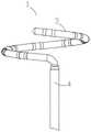
1-环形远端1 - Ring distal end
2-电极对2- Electrode pair
3-末端管体3-Terminal Body
4-末端硬管4-End Hard Tube
41-定位电极41 - Positioning Electrodes
42-牵引组件42 - Traction Assembly
5-远端管体5 - Distal body
6-近端管体6-Proximal body
7-支撑构件7-Support member
71-支撑构件头端71-Support member head end
72-支撑构件近端72-Proximal end of support member
8-防损伤头端8-Anti-damage head end
9-收缩绳9-shrink rope
10-保护管10-Protection tube
11-环电极11-ring electrode
12-环电极12-ring electrode
131-第一定位传感器131-First positioning sensor
132-第二定位传感器132-Second positioning sensor
133-第三定位传感器133-Third positioning sensor
14-护套管14-Sheathing tube
15-手柄组件15-Handle assembly
16-推钮16-Push button
17-旋钮17-Knob
171-滑动块171-Slider
172-旋转芯轴172-Rotating Mandrel
173-滑动槽173-Sliding groove
18-第一连接器18-First connector
19-第二连接器19-Second connector
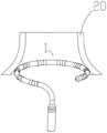
20-腔道结构20-cavity structure
111-第一电极对111-First electrode pair
112-第二电极对112-Second electrode pair
113-第三电极对113-Third electrode pair
114-第四电极对114 - Fourth electrode pair
115-第五电极对115-Fifth electrode pair
116-第六电极对116-Sixth electrode pair
117-第七电极对117-Seventh electrode pair
118-第八电极对118-Eighth electrode pair
119-第九电极对119-Ninth electrode pair
21-心肌组织21 - Myocardial tissue
22-放电形成的电场区域22- Electric field region formed by discharge
具体实施方式Detailed ways
下面通过实施例,并结合附图,对本发明的技术方案作进一步详细的说明,但本发明不限于下面的实施例。The technical solutions of the present invention will be described in further detail below through the examples and in conjunction with the accompanying drawings, but the present invention is not limited to the following examples.
消融导管Ablation catheter
图1是根据本发明的消融导管的整体示意图。Figure 1 is an overall schematic view of an ablation catheter according to the present invention.
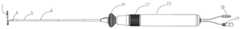
如图1所示,根据本发明的消融导管在整体结构上从远端到近端依次可以包括环形远端1、末端硬管4、远端管体5、近端管体6、手柄组件15、连接器18和19。环形远端1设置在导管的最远端。末端硬管4用于连接环形远端1与远端管体5。末端硬管4优选材质硬度较高的聚醚醚酮高分子材料。远端管体5设置在近端管体6与末端硬管4之间。远端管体5在手柄组件15的操控下可进行弯曲,用于使环形远端1到达预期部位。近端管体6用于连接远端管体5与手柄组件15。图1中所示的消融导管的连接器至少包括两种连接器:连接器18用于在导管与设备间传输定位信息,连接器19用于与设备之间进行消融能量的传输。As shown in FIG. 1 , the overall structure of the ablation catheter according to the present invention may include an annular
图1所示的消融导管还包括在近端管体6和手柄组件15之间的推钮16、手柄组件15上的旋钮17。The ablation catheter shown in FIG. 1 also includes a push button 16 between the
在本公开的表述中,“远端”和“近端”是相对于导管操作者而言的,例如,远端可以是更靠近待消融组织的一端,而近端可以是更靠近导管操作者的一端。此外,“头端”和“末端”一般是指自由端和固定端(或称“连接端”)。In the expressions of the present disclosure, "distal" and "proximal" are relative to the catheter operator, for example, the distal end may be the end closer to the tissue to be ablated, and the proximal end may be closer to the catheter operator one end. In addition, "head end" and "end" generally refer to the free end and the fixed end (or "connected end").
本领域技术人员应该理解,尽管将上述元件和组件组合在一起形成根据本发明的消融导管的一个优选实施例,然而根据本发明的消融导管并不限于包括所有这些元件和组件。It will be understood by those skilled in the art that although the above-described elements and components are combined together to form a preferred embodiment of an ablation catheter according to the present invention, ablation catheters according to the present invention are not limited to including all of these elements and components.
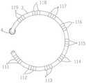
图2是环形远端的自然状态示意图。如图2所示,环形远端在自然状态下外径为20-35毫米,呈现字母“C”形的外观。环形远端的头端是防损伤头端8,末端是硬端,头端和末端之间分离一定距离,这个分离距离为大致圆形结构的1/4-1/5。环形远端自然状态下呈螺旋状,环形远端上设置有与环形远端的形状相应而呈弧形的末端管体3。末端管体3优选由高弹性的聚氨酯材料支撑。末端管体3上设置有多个电极对2。在本发明的优选实施例中,电极对的数量为2N+1个,N为正整数。每个电极对都由两个电极组成。例如,在距离头端(防损伤头端8)最近的第一个电极对是由环电极11和环电极12组成的。Figure 2 is a schematic diagram of the natural state of the annular distal end. As shown in Figure 2, the annular distal end has an outer diameter of 20-35 mm in its natural state, and has the appearance of the letter "C". The head end of the annular distal end is the
简言之,根据本发明的消融导管具有环形远端1。环形远端1包括呈弧形的末端管体3。本发明的创新点在于,沿末端管体的弧形延伸方向间隔设置有多个电极对。这多个电极对2分别都环绕在末端管体3上。Briefly, the ablation catheter according to the present invention has an annular
图2还示出了末端硬管4及其上设置的定位电极41,下文将有对定位电极41更详细的描述。FIG. 2 also shows the end
结合图1和图2可知,末端管体3的一端为自由端,处于环形远端1的头端。所述自由端上具有防损伤头端8。末端管体3的另一端为固定端。末端硬管4一端连接到末端管体3的固定端。远端管体5一端连接到末端硬管4的另一端。近端管体6一端连接到远端管体5的另一端。手柄组件15一端连接到近端管体6的另一端。可以在手柄组件15和近端管体6之间设置推钮16。另外,可以在手柄组件15上设置旋钮17。连接器18、19连接到手柄组件15的另一端。1 and 2 , one end of the
图3是环形远端的自然状态下电极对设置的示意图。例如,如图3中所示,第一电极对111由两个微细环电极组成。环电极优选为黄金或铂金电极,在末端管体的弧形延伸方向上的尺寸(可以称之为“长度”或者“宽度”)为0.50-1.5毫米。环电极之间的净空间距为1-3毫米。环电极对之间的净空间距为3-6毫米。这里需要注意的是,这里所采用的电极宽度、间距等的设计初衷在于,由于环形远端的直径可收缩,所以电极尺寸需要与之相适应,特别是在末端管体的弧形延伸方向上的电极尺寸即所谓的“长度”或“宽度”需要适当,尺寸过大将影响环形远端的收缩效果,因此设置为两个环电极组成为一组电极对。Figure 3 is a schematic diagram of the electrode pair arrangement in the natural state of the annular distal end. For example, as shown in FIG. 3 , the
简言之,每个电极对2都包括环绕在末端管体3上的两个环电极,例如环电极11和12,每个环电极在末端管体的弧形延伸方向上的宽度、同一个电极对中两个环电极的间距、相邻电极对之间的间距需要被设置为合适的尺寸。在优选实施例中,这些尺寸与每个环电极的直径之间存在一定的约束关系(下文将更详细描述)。In short, each
在本公开中使用了“在末端管体的弧形延伸方向上的尺寸”、“间距”等术语来表示与待消融的心肌组织相接触的环形远端的环形或弧形周长上的尺寸,而并非表示末端管体或环形远端的管体粗细方面的尺寸。本领域技术人员应该理解,这样的尺寸既可以被描述为“长度”,也可以被描述为“宽度”,默认情况下,无论“长度”或“宽度”,指的都是在环形周长上的尺寸,而并非表示管体粗细方面的尺寸。The terms "dimension in the arcuate extension of the distal body", "pitch", etc. are used in this disclosure to refer to the dimension on the annular or arcuate perimeter of the annular distal end that is in contact with the myocardial tissue to be ablated , rather than dimensions in terms of body thickness at the end body or the annular distal end. It should be understood by those skilled in the art that such dimensions can be described as both "length" and "width". By default, either "length" or "width" refers to the circumference of the ring size, rather than the size of the tube body thickness.
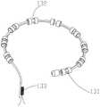
如前所述,环形远端上可以设置有2N+1个(奇数个)环电极对。如图3中所示,放电消融时,第一电极对到第九电极111-119呈正负交替加载电压,例如第一电极对111加载正极,第二电极对112加载负极,依次顺序加载,也就是说,相邻的电极对的极性相反。图3中最后一个电极对是第九电极对119,其极性为正。由于电极对的数量为奇数个,所以最末电极对与第一电极对的极性是相同的。例如,第一电极对111和第九电极对119的极性都为正。这样设置的目的是为了确保环形远端收缩时,即使电极发生搭接,也不发生电弧问题,从而保证了使用的安全性。在消融模式下,电极对中的两个电极在放电消融时极性相同,可等效视为一个电极。分离式的电极对的设计(由两个环电极构成)可以减少末端管体的刚性,便于环形远端尺寸收缩。As previously mentioned, there may be 2N+1 (odd number) of ring electrode pairs disposed on the distal end of the ring. As shown in FIG. 3 , during discharge ablation, the first electrode pair to the ninth electrodes 111-119 are alternately loaded with positive and negative voltages, for example, the
如图13所示,环电极可以为螺旋电极。螺旋电极为电极导线绕制或者是环形电极进行切割成螺旋形态的电极。As shown in Figure 13, the ring electrode may be a helical electrode. The spiral electrode is an electrode that is wound by electrode wire or cut into a spiral shape by a ring electrode.
回过来看图3,将环电极设置在末端管体3上时,可以减少末端管体刚性,便于环形远端直径收缩。电极对111-119均为环状,优选以等间距的形式,环绕在末端管体3上。末端管体3与末端硬管4相连接。电极材料可以为铂铱合金、黄金。Looking back at FIG. 3 , when the ring electrode is arranged on the
在本发明的优选实施例中,消融导管是脉冲电场消融导管,用于传递与释放脉冲消融能量至预期消融部位。也就是说,消融导管主要用于通过向人体组织施加高压脉冲电场来进行消融。更具体地,根据本发明的消融导管可以用于心脏及其周边组织的消融。In a preferred embodiment of the present invention, the ablation catheter is a pulsed electric field ablation catheter for delivering and releasing pulsed ablation energy to the intended ablation site. That is, the ablation catheter is mainly used for ablation by applying a high-voltage pulsed electric field to human tissue. More specifically, the ablation catheter according to the present invention can be used for ablation of the heart and surrounding tissue.
由于脉冲电场消融为电极之间加载高电压进行放电消融,电压为1000-4000V,因此要求电极表面积需足够大,否则在放电时会因局部场强过于集中而产生电弧现象。但是,如前所述,要兼顾环形远端直径可调节问题,因此电极设置为电极对布置。单个电极间隔一定较短的距离后再设置一个电极,从而这两个电极能够形成电极对,在放电时将这一对电极(电极对)等效地视为一个电极,发挥出表面积足够大的电极的放电作用,同时又不会因为电极尺寸太大而影响到环形远端的直径调节。Since the pulsed electric field ablation is performed by loading a high voltage between the electrodes for discharge ablation, the voltage is 1000-4000V, so the electrode surface area must be large enough, otherwise, the arc phenomenon will be generated due to the excessive concentration of the local field intensity during discharge. However, as mentioned earlier, the adjustable diameter of the annular distal end has to be taken into account, so the electrodes are arranged in an electrode pair arrangement. A single electrode is separated by a certain short distance and then an electrode is set, so that the two electrodes can form an electrode pair, and this pair of electrodes (electrode pair) is equivalently regarded as an electrode during discharge, and the surface area is large enough. The discharge effect of the electrode will not affect the diameter adjustment of the distal end of the ring because the size of the electrode is too large.
另一方面,电极对中的两个电极间距较近,可以同时分别单独用于标测作用。由于脉冲电场能量输出较高且集中,因此要求加载的正负电极之间的距离应尽量大一些,但过大的电极间距将使采集的电生理信号范围过大,影响局部消融效果判断。因此,在消融完成后,使用电极对中的两个间距较近的电极进行电生理信号的采集,由此判断电生理信号更加精准,可以更加精细地判断局部电信号,避免过大的电极间距引入大范围的电生理信号而影响消融效果判断。On the other hand, the two electrodes in the electrode pair are closely spaced and can be used for mapping independently at the same time. Due to the high and concentrated energy output of the pulsed electric field, the distance between the positive and negative electrodes to be loaded should be as large as possible, but an excessive electrode distance will make the range of collected electrophysiological signals too large, affecting the judgment of local ablation effects. Therefore, after the ablation is completed, the electrophysiological signals are collected by using the two electrodes in the electrode pair that are closely spaced, so that the electrophysiological signals can be judged more accurately, and the local electrical signals can be judged more precisely, so as to avoid excessive electrode spacing. The introduction of a large range of electrophysiological signals affects the judgment of the ablation effect.
因此,简言之,当用于脉冲电场消融时,消融导管处于消融模式下,每个电极对中的两个电极的极性相同,由此可以被等效为同一个电极施加电压,从而在消融时起到一个表面积足够大的电极的放电作用。同时,相邻的电极对的极性是相反的。Therefore, in short, when used for pulsed electric field ablation, the ablation catheter is in the ablation mode, and the polarity of the two electrodes in each electrode pair is the same, so it can be equivalently applied to the same electrode, so that in the During ablation, it acts as a discharge of an electrode with a sufficiently large surface area. Meanwhile, the polarities of adjacent electrode pairs are opposite.
另一方面,当用于电生理标测时,消融导管处于标测模式下,每个电极对中的两个电极分别发挥作用,即被分别独立用来采集电生理信号,起到两个间距较近的电极的作用。On the other hand, when it is used for electrophysiological mapping, the ablation catheter is in the mapping mode, and the two electrodes in each electrode pair play their roles respectively, that is, they are independently used to collect electrophysiological signals, and play two spacings. The effect of the closer electrode.
图4是远端管体牵引组件布置的示意图。如图4所示,环形远端1设置在末端硬管4上。末端管体3在靠近近端方向上的不弯曲段与末端硬管4相连接。末端硬管4内部放置有牵引组件42。牵引组件42固定在末端硬管4上,在手柄组件15与近端管体6之间的推钮16的控制下可实现远端管体5弯曲(参考图14)。末端硬管4上设置有定位电极41,用于配合定位传感器(例如下文中所述的定位传感器131、132、133)的定位。Figure 4 is a schematic illustration of the arrangement of the distal tubular body traction assembly. As shown in FIG. 4 , the annular
图5是环形远端的收缩状态示意图。图6是环形远端的收缩状态下电极对设置的示意图。图10是环形远端拉伸侧面示意图。图15是环形远端的收缩控制组件的内部示意图。Figure 5 is a schematic diagram of the retracted state of the annular distal end. Figure 6 is a schematic illustration of the electrode pair arrangement in the retracted state of the annular distal end. Figure 10 is a schematic side view of the annular distal stretch. Figure 15 is an internal schematic view of the retraction control assembly of the annular distal end.
如前所述,手柄组件15上可以具有旋钮17。通过旋转旋钮17,可以控制收缩绳的收缩与恢复,从而实现环形远端的环形直径的变化。As previously mentioned, the
参考图5、6、10、15,更具体如图15所示,当操控手柄组件15上的旋钮17时,滑动块171会带动收缩绳9移动。收缩绳9和滑动块171固定在一起。旋转芯轴172内部设置有内螺纹,与滑动块171上的外螺纹配合。当顺时针旋转旋钮17时,旋钮17将带动旋转芯轴172转动,旋转芯轴172将使滑动块171向后移动,拉动收缩绳9,进而实现环形远端1收缩。当逆时针旋转旋钮17时,收缩绳9恢复,环形远端1直径实现增大或恢复。5 , 6 , 10 , and 15 , and more specifically as shown in FIG. 15 , when the
如前所述,在自然状态下,环形远端呈现螺旋状环形,环形直径为20-35毫米。环形远端1的头端和末端之间分离,该分离的距离为圆环周长的1/5-1/4。如图5、6、10所示,当环形远端1收缩到最小时,末端管体3上首尾两个电极对111与电极对119不发生搭接,进一步增加安全性。环形远端直径收缩到最小时环形远端1在环形截面上呈封闭的圆环,环形直径为12-15毫米,头端和末端上的电极对不发生搭接。图5和图10中除了示出末端管体3和电极对(例如111和119)之外,还示出了末端硬管4或其一部分。As previously mentioned, in the natural state, the distal end of the ring presents a helical ring with a ring diameter of 20-35 mm. The head end and the end of the annular
根据本发明的消融导管可以进一步包括贯穿设置在末端管体和末端硬管内部的支撑构件以及设置在支撑构件的环形内侧的收缩绳。收缩绳的一端与支撑构件的一端共同固定于防损伤头端。收缩绳收缩时带动支撑构件形变,以调节环形远端的环形直径。The ablation catheter according to the present invention may further comprise a support member disposed through the distal tube body and the distal end tube and a retraction cord disposed inside the annular shape of the support member. One end of the retraction cord is fixed to the atraumatic head end together with one end of the support member. When the retraction cord is retracted, the supporting member is deformed to adjust the annular diameter of the annular distal end.
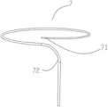
图7是支撑构件的示意图。如图7所示,支撑构件7呈环形状。环形远端的形状主要为支撑构件的形状决定。支撑构件的材料为具有高弹性的记忆合金材料,如镍钛合金(NiTi)等,能自去除外界力后瞬间恢复原始形态。在优选实施例中,支撑构件头端71与支撑构件近端72直径不一致。为实现环形远端的直径可调节功能,支撑构件头端71的直径小于支撑构件近端72的直径,且头端到近端,直径是渐变式增大。为实现环形远端1收缩,在收缩绳9的作用下,环形远端1收缩,但若头端刚性过大,便不能实现头端变形以及收缩,因此头端直径小于近端,且依次渐变式增大,头端直径为近端直径的1/3-4/5。收缩绳9材质优选为柔性且具有较高抗拉强度的不锈钢丝绳,直径0.10-0.15毫米。柔软的收缩绳9将不会引起环形远端1的刚性增加,进而影响环形圈的变形。收缩绳9也可以为聚乙烯绳(PE绳),柔软且具有较高的抗拉强度。有关收缩绳9,在下文中还将详细描述。Figure 7 is a schematic view of a support member. As shown in FIG. 7 , the
图8是环形远端内部示意图。图9是环形远端中定位传感器布置示意图。图11是环形远端头端剖面示意图。Figure 8 is a schematic diagram of the inside of the annular distal end. Figure 9 is a schematic diagram of the positioning sensor arrangement in the annular distal end. Figure 11 is a schematic cross-sectional view of the annular distal tip.
如图8所示,在支撑构件7的环形内侧设置收缩绳9,以利用收缩绳9带动支撑构件7形变,从而造成环形远端1的直径变化,即,使得环形远端1的环形直径可以收缩。支撑构件7与收缩绳9共同固定在环形远端1头端末端的防损伤头端8内部。如图11所示,使用保护管10包裹在支撑构件7和收缩绳9的外部。保护管10用于保护收缩绳9在收缩时不影响末端管体3内部的器件,同时使收缩绳9的收缩更加顺滑。保护管10的材质优选为聚四氟乙烯管材。As shown in FIG. 8 , a
在本发明的优选实施例中,可以在电极对的下方设置定位传感器,使定位传感器处于末端管体的内部。In a preferred embodiment of the present invention, a positioning sensor can be arranged below the electrode pair, so that the positioning sensor is located inside the end pipe body.
如图9所示,第一定位传感器131设置在环形远端1的头端,第一个电极对111下面。第二定位传感器132设置在环形远端1的中间位置,例如可以在环形远端1中间段位置处的电极对的下方,例如在第六电极对116的下方。第三定位传感器133设置在末端硬管4内部。这些定位传感器配合定位电极41(图2、图4),以及末端管体3上的电极,能显示环形远端1形态以及电极的位置关系,便于观察电极之间是否存在搭接,以便更好保证电极的安全性。依靠磁定位功能可以监控最易搭接位置,以在极端状况下限制能量输出。定位传感器在末端管体的弧形延伸方向上的尺寸(例如可被称为“长度”)等于两个环电极分别的尺寸(在末端管体的弧形延伸方向上的“长度”或“宽度”)及其间距之和,也就是一个电极对的尺寸(一个电极对在末端管体的弧形延伸方向上的宽度),且设置在电极对正下方。如此设计就是为了避免增加环形段刚性。定位传感器为圆柱体结构,中间为空心。由此,支撑构件7可以穿过该圆柱体结构的中心并将定位传感器固定在支撑构件7上。定位传感器为铜导线螺旋绕制的圆柱体结构,本身具有一定弹性,在外侧高弹性的聚氨酯材质保护固定后,形成可自由变形且不影响性能的定位传感器,适合用在环形可调节的环形圈上。As shown in FIG. 9 , the
如图11所示,每个定位传感器都设置固定在支撑构件7上。为了稳定地固定在其上,将第一定位传感器131与保护管10(包括保护管10内的支撑构件7、收缩绳9)用护套管14进行固定。同理,也可以将第二定位传感器132与保护管10用护套管14进行固定。护套管14的材料优选为高弹性的聚氨酯管材,具有高弹性且便于粘接。支撑构件7、收缩绳9以及保护管10在防损伤头端8处固定在一起。在图11的示意中,定位传感器131设置在环形远端1的头端,第一对环电极11和12下面。定位传感器131在末端管体的弧形延伸方向上的尺寸(例如可被称为“长度”)等于两个环电极11和12的尺寸(在末端管体的弧形延伸方向上的“长度”或“宽度”)以及其间距,也就是一个电极对的尺寸,且设置在这对电极11和12的正下方。As shown in FIG. 11 , each positioning sensor is provided and fixed on the
如图11所示,在保护管10的外周上固定第一定位传感器131。由于第一定位传感器131为圆柱体结构,中间为空心,保护管10可以穿过第一定位传感器131的圆柱体结构的中心。也就是说,支撑构件7穿过第一定位传感器131的圆柱体结构的中心。As shown in FIG. 11 , the
同理,也可以在保护管10的外周上固定第二定位传感器132。由于第二定位传感器132为圆柱体结构,中间为空心,保护管10可以穿过第二定位传感器132的圆柱体结构的中心。也就是说,支撑构件7穿过第二定位传感器132的圆柱体结构的中心。Similarly, the
图12是远端管体截面示意图。图14是远端管体弯折效果示意图。Figure 12 is a schematic cross-sectional view of the distal tube body. Figure 14 is a schematic diagram of the bending effect of the distal tube body.
如前所述,根据本发明的消融导管可以进一步包括推纽16,其设置在手柄组件15和近端管体6之间。根据本发明的优选实施例,推扭15连接设置在远端管体5内的牵引组件42的一端。牵引组件42的另一端则连接末端硬管4。通过推动推扭16,可以控制牵引组件42的松紧,由此实现远端管体5打弯。As previously described, the ablation catheter according to the present invention may further include a push button 16 disposed between the
如图12、14所示,推动推钮16可控制远端管体5打弯,以帮助环形远端1达到目标位置。如图12所示,远端管体5为多腔管结构,环形远端1的收缩绳9放置中间腔。因为放置在中间腔,当收缩绳9收缩运动时不会影响远端管体5弯曲以及带动远端管体5折弯。牵引组件42设置在远端管体5的侧边,以便于远端管体5弯曲的同时不影响中间的收缩绳9。收缩绳9在中间,无论远端管体5在弯曲或伸直状态下均不会引起收缩绳9相对运动。这样就避免了环形远端1收缩与远端管体5弯曲可能会相互干涉的问题。As shown in Figures 12 and 14, pushing the push button 16 can control the
图14中示出了与图1中相同的元件和组件,即除了推钮16、旋钮17之外,还包括环形远端1、末端硬管4、远端管体5、近端管体6、手柄组件15、连接器18和19。本领域技术人员应该理解,尽管将上述元件和组件组合在一起形成根据本发明的消融导管的一个优选实施例,然而根据本发明的消融导管并不限于包括所有这些元件和组件。14 shows the same elements and components as in FIG. 1 , namely, in addition to the push button 16, the
此外,如前所述,图1、14中所示的消融导管的连接器至少包括两种连接器:连接器18用于在导管与设备间传输定位信息,连接器19用于与设备之间进行消融能量的传输。参考图11的描绘可知,连接器18通过第一线缆与定位传感器连接,从而传输定位信息。连接器19则通过第二线缆分别与每个电极对上的环电极连接,从而传输消融能量;另外在消融导管处于标测模式下,连接器19和第二线缆还可用来采集电生理标测信号。In addition, as mentioned above, the connectors of the ablation catheters shown in Figures 1 and 14 include at least two types of connectors: the
应用实施例Application Example
下面来通过应用实施例更详细说明根据的本发明环形远端直径可变的消融导管的具体使用情况。The specific use of the annular ablation catheter with variable distal diameter according to the present invention will be described in more detail below through application examples.
图16是根据本发明的实施例的一个应用示意图。图17是根据本发明的实施例的另一个应用示意图。FIG. 16 is a schematic diagram of an application according to an embodiment of the present invention. FIG. 17 is another application schematic diagram according to an embodiment of the present invention.
在图16和17的应用实施例中,可以包括如下的操作步骤:In the application embodiments of FIGS. 16 and 17 , the following operation steps may be included:
第一步:如图16所示,将环形远端1直径收缩为小直径环形远端1,然后伸入腔道结构20;The first step: as shown in Figure 16, the diameter of the annular
第二步:对腔道结构20内部进行电生理信号标测以及构建腔道结构20物理模型;The second step: performing electrophysiological signal mapping inside the
第三步:如图17所示,控制环形远端1直径增大,使电极能与腔道结构20进行很好的贴靠;The third step: as shown in FIG. 17 , the diameter of the
第四步:放电消融,电压幅值为1000-4000V。消融后通过电极对里的两个电极采集电生理信号。通过比较电生理信号的变化可以确定即刻消融效果,直至腔道结构20电活动被完全隔离。The fourth step: discharge ablation, the voltage amplitude is 1000-4000V. After ablation, electrophysiological signals are collected through two electrodes in the electrode pair. The immediate ablation effect can be determined by comparing changes in the electrophysiological signals until the electrical activity of the
图18是根据本发明的消融导管释放电场能量时的电场分布示意图。18 is a schematic diagram of the electric field distribution when the ablation catheter according to the present invention releases electric field energy.
如图18所示,进行脉冲放电时,消融导管上的所有电极在心肌组织21中形成了连续的消融带,即图中所示的放电形成的电场区域22。一般地,心肌消融有效性阈值为400V/CM。在电场区域22中,电压强度均大于400V/CM,达到了该阈值,从而在这个连续区域上都能够进行有效地心肌消融。电极对数量为2N+1个(N为正整数)。每个电极对由两个环电极组成,如图18中所示,电极对数量为9对。无论第一电极对111还是第九电极对119都是由两个微细环电极组成。环电极优选为黄金或铂金电极,尺寸(末端管体的弧形延伸方向上的“长度”或“宽度”)为0.50-1.5毫米,环电极之间的净空间距为1-3毫米,环电极对之间的净空间距为3-6毫米,施加的脉冲电场幅值为1000-4000V。为提升消融效率,电极放电时应形成连续的消融带,以防止消融漏点。根据电极形成电场分布与力学设计,在保证电极对表面积足够大,且电极对之间间距适当前提下,放电消融时形成连续的消融带且保证环形可调节功能,有如下关系:As shown in FIG. 18 , when the pulsed discharge is performed, all electrodes on the ablation catheter form a continuous ablation zone in the
(2×L+d)×k=D,且S>D,(2×L+d)×k=D, and S>D,
其中,L为环电极在末端管体弧形延伸方向上的宽度(或称为“长度”),d为同一电极对中两个环电极的间距,D为相邻电极对之间的间距,S为每个环电极的直径,k为修正系数且取值在0.7-1.4之间(k=0.7-1.4)。如前所述,在优选实施例中,L取值为0.50-1.5毫米,d取值为1-3毫米,D取值为3-6毫米。Among them, L is the width (or "length") of the ring electrode in the arc extending direction of the end tube body, d is the distance between two ring electrodes in the same electrode pair, D is the distance between adjacent electrode pairs, S is the diameter of each ring electrode, and k is a correction coefficient, and the value is between 0.7-1.4 (k=0.7-1.4). As mentioned above, in a preferred embodiment, L is 0.50-1.5 mm, d is 1-3 mm, and D is 3-6 mm.
本领域技术人员应该理解,尽管上面的各种实施例中分别提到了消融导管的各种元件和组件,然而,除非上述说明书中明确排除或者实践中不允许或无法实现,这些元件和组件是可以任意组合在消融导管之中,从而发挥各自的作用以实现相应功能的。上述实施例或实施方式均无法限制本发明的范围。It should be understood by those skilled in the art that although various elements and components of the ablation catheter are respectively mentioned in the various embodiments above, unless explicitly excluded in the above description or not allowed or impossible in practice, these elements and components can be Arbitrary combination in the ablation catheter, so as to play their respective roles to achieve corresponding functions. None of the above examples or embodiments limit the scope of the present invention.
电极功能控制方法Electrode function control method
由于本发明的消融导管可以分别在消融模式下和标测模式下使用,所以可以相应地控制消融导管上的电极和电极对,使之在不同模式下可以分别发挥不同作用以实现不同功能。Since the ablation catheter of the present invention can be used in the ablation mode and the mapping mode respectively, the electrodes and electrode pairs on the ablation catheter can be controlled accordingly, so that they can play different roles in different modes to achieve different functions.
具体地说,本发明提议一种用于控制如本发明所述的消融导管上的电极对的功能的方法。消融导管具体是用于心脏及其周边组织消融的脉冲电场消融导管。根据本发明提议的方法,在导管的消融模式下,向每个电极对中的两个间距较小的电极传输极性相同的电场能量,使电极对中的两个电极等效为尺寸或表面积较大的同一个电极向相应组织施加电压,而向相邻的电极对传输极性相反的电场能量,以实现脉冲电场消融功能。另一方面,在导管的标测模式下,将每个电极对中的两个间距较小的电极分别单独使用,即通过每个电极对中的两个电极来分别独立采集电生理信号,以实现电生理标测功能。Specifically, the present invention proposes a method for controlling the function of electrode pairs on an ablation catheter as described in the present invention. The ablation catheter is specifically a pulsed electric field ablation catheter used for ablation of the heart and surrounding tissues. According to the method proposed by the present invention, in the ablation mode of the catheter, electric field energy of the same polarity is delivered to the two closely spaced electrodes in each electrode pair, so that the two electrodes in the electrode pair are equivalent in size or surface area The larger same electrode applies voltage to the corresponding tissue, and transmits electric field energy of opposite polarity to the adjacent electrode pair, so as to realize the pulse electric field ablation function. On the other hand, in the mapping mode of the catheter, the two electrodes with smaller spacing in each electrode pair are used separately, that is, the electrophysiological signals are collected independently through the two electrodes in each electrode pair, so as to Realize the function of electrophysiological mapping.
计算机程序或计算机程序产品以及计算机可读介质Computer program or computer program product and computer readable medium
此外,本领域普通技术人员应该认识到,本公开的方法可以实现为计算机程序。通过一个或多个程序执行上述方法,包括指令来使得计算机或处理器执行相应算法。这些程序可以使用各种类型的非瞬时计算机可读介质存储并提供给计算机或处理器。非瞬时计算机可读介质包括各种类型的有形存贮介质。非瞬时计算机可读介质的示例包括磁性记录介质(诸如软盘、磁带和硬盘驱动器)、磁光记录介质(诸如磁光盘)、CD-ROM(紧凑盘只读存储器)、CD-R、CD-R/W以及半导体存储器(诸如ROM、PROM(可编程ROM)、EPROM(可擦写PROM)、闪存ROM和RAM(随机存取存储器))。进一步,这些程序可以通过使用各种类型的瞬时计算机可读介质而提供给计算机。瞬时计算机可读介质的示例包括电信号、光信号和电磁波。瞬时计算机可读介质可以用于通过诸如电线和光纤的有线通信路径或无线通信路径提供程序给计算机。Furthermore, one of ordinary skill in the art will recognize that the methods of the present disclosure can be implemented as computer programs. The above-described methods are performed by one or more programs, including instructions to cause a computer or processor to execute the corresponding algorithm. These programs can be stored and provided to a computer or processor using various types of non-transitory computer-readable media. Non-transitory computer readable media include various types of tangible storage media. Examples of non-transitory computer-readable media include magnetic recording media (such as floppy disks, magnetic tapes, and hard drives), magneto-optical recording media (such as magneto-optical disks), CD-ROMs (Compact Disc Read Only Memory), CD-Rs, CD-Rs /W and semiconductor memories such as ROM, PROM (Programmable ROM), EPROM (Erasable PROM), Flash ROM and RAM (Random Access Memory). Further, these programs can be provided to a computer by using various types of transitory computer-readable media. Examples of transitory computer-readable media include electrical signals, optical signals, and electromagnetic waves. Transitory computer readable media can be used to provide the program to a computer through wired or wireless communication paths such as wires and optical fibers.
例如,根据本公开的一个实施例,可以提供一种计算机可读介质,其上存储有可由处理器执行的指令,所述指令在被处理器执行时,使得处理器执行如前所述的用于控制消融导管上的电极对的功能的方法。For example, according to one embodiment of the present disclosure, there may be provided a computer-readable medium having stored thereon instructions executable by a processor that, when executed by the processor, cause the processor to perform the functions described above. Methods for controlling the function of electrode pairs on an ablation catheter.
根据本发明公开的内容,还可以提议一种计算机程序或计算机程序产品,当所述计算机程序被执行时,可实现如前所述的用于控制消融导管上的电极对的功能的方法。According to the present disclosure, it is also possible to propose a computer program or computer program product which, when executed, can implement the method for controlling the function of electrode pairs on an ablation catheter as previously described.
另外,本发明还涉及一种计算装置或计算系统,包括处理器和存储器,所述存储器中存储有计算机程序,当所述计算机程序由所述处理器执行时,可实现如前所述的用于控制消融导管上的电极对的功能的方法。In addition, the present invention also relates to a computing device or computing system, comprising a processor and a memory, wherein a computer program is stored in the memory, and when the computer program is executed by the processor, the aforementioned functions can be implemented. Methods for controlling the function of electrode pairs on an ablation catheter.
有益效果beneficial effect
综上所述,根据本发明的消融导管至少具有以下的有益效果:To sum up, the ablation catheter according to the present invention has at least the following beneficial effects:
1.可调节环形远端大小的脉冲导管设计适用不同的腔道结构,可调节方式有利于环形远端上的电极能更好的与组织结构进行贴靠。1. The design of the pulse catheter with adjustable annular distal end size is suitable for different cavity structures, and the adjustable way is beneficial to the electrodes on the annular distal end to better adhere to the tissue structure.
2.电极对设计在保证消融有效性与安全性前提下,更加便于环形远端直径调节,同时电极对用于电生理信号采集更加精确,避免电极间距过大影响电信号变化判断。2. The electrode pair design is more convenient to adjust the diameter of the distal end of the ring under the premise of ensuring the effectiveness and safety of ablation. At the same time, the electrode pair is used to collect electrophysiological signals more accurately, avoiding excessive electrode spacing to affect the judgment of electrical signal changes.
3.该发明电极设计具有在消融时电极对合并为一个电极进行消融,标测时电极对分离为两个电极进行标测,充分兼顾脉冲电场消融的有效性与电生理标测的精确性。3. The electrode design of the invention has the advantages that the electrode pair is combined into one electrode for ablation during ablation, and the electrode pair is separated into two electrodes for mapping during mapping, fully taking into account the effectiveness of pulsed electric field ablation and the accuracy of electrophysiological mapping.
4.提出可自由变形且不影响性能的定位传感器的设置方式,适用于导管的可调节直径的环形段上,使得消融导管在操作中可以提供形态与电极间距实时显示,以指导术者精确的消融操作,同时能监控电极间距以增加安全性。4. Propose the setting method of the positioning sensor that can be freely deformed and does not affect the performance, which is suitable for the annular segment of the catheter with adjustable diameter, so that the ablation catheter can provide real-time display of the shape and electrode spacing during operation, so as to guide the operator accurately. Ablation procedures, while monitoring electrode spacing for added safety.
5.高压脉冲能量精确有效地施加至目标组织,大大缩短手术时间,高压脉冲能量可以选择性地消融目标组织,减少并发症。5. The high-voltage pulse energy is accurately and effectively applied to the target tissue, which greatly shortens the operation time. The high-voltage pulse energy can selectively ablate the target tissue and reduce complications.
6.导管具备标测、建模、消融为一体的功能,可节约手术时间以及费用。6. The catheter has the functions of mapping, modeling and ablation, which can save operation time and cost.
本发明的实施方式并不限于上述实施例所述,在不偏离本发明的精神和范围的情况下,本领域普通技术人员可以在形式和细节上对本发明做出各种改变和改进,而这些均被认为落入了本发明的保护范围。The embodiments of the present invention are not limited to those described in the above-mentioned embodiments, without departing from the spirit and scope of the present invention, those skilled in the art can make various changes and improvements to the present invention in form and detail, and these All are considered to fall within the protection scope of the present invention.
Claims (31)
Priority Applications (4)
| Application Number | Priority Date | Filing Date | Title |
|---|---|---|---|
| CN202210102213.XACN114366286B (en) | 2022-01-27 | 2022-01-27 | Ablation Catheter |
| EP22923365.5AEP4470489A1 (en) | 2022-01-27 | 2022-10-31 | Ablation catheter |
| JP2024543201AJP2025503056A (en) | 2022-01-27 | 2022-10-31 | Ablation Catheters |
| PCT/CN2022/128641WO2023142567A1 (en) | 2022-01-27 | 2022-10-31 | Ablation catheter |
Applications Claiming Priority (1)
| Application Number | Priority Date | Filing Date | Title |
|---|---|---|---|
| CN202210102213.XACN114366286B (en) | 2022-01-27 | 2022-01-27 | Ablation Catheter |
Publications (2)
| Publication Number | Publication Date |
|---|---|
| CN114366286Atrue CN114366286A (en) | 2022-04-19 |
| CN114366286B CN114366286B (en) | 2024-11-22 |
Family
ID=81145718
Family Applications (1)
| Application Number | Title | Priority Date | Filing Date |
|---|---|---|---|
| CN202210102213.XAActiveCN114366286B (en) | 2022-01-27 | 2022-01-27 | Ablation Catheter |
Country Status (4)
| Country | Link |
|---|---|
| EP (1) | EP4470489A1 (en) |
| JP (1) | JP2025503056A (en) |
| CN (1) | CN114366286B (en) |
| WO (1) | WO2023142567A1 (en) |
Cited By (8)
| Publication number | Priority date | Publication date | Assignee | Title |
|---|---|---|---|---|
| CN115137466A (en)* | 2022-07-11 | 2022-10-04 | 洲瓴(上海)医疗器械有限公司 | Electrode catheter for pulse electric field ablation |
| CN115429420A (en)* | 2022-09-02 | 2022-12-06 | 深圳惠泰医疗器械股份有限公司 | Adjustable bending magnetic positioning high-density mapping ablation electrode catheter |
| CN116115331A (en)* | 2023-02-07 | 2023-05-16 | 上海博动医疗科技股份有限公司 | A pulse ablation system |
| WO2023142567A1 (en)* | 2022-01-27 | 2023-08-03 | 四川锦江电子医疗器械科技股份有限公司 | Ablation catheter |
| CN117442325A (en)* | 2023-10-25 | 2024-01-26 | 四川锦江生命科技有限公司 | Multipolar ablation electrode catheter |
| CN117694997A (en)* | 2024-02-05 | 2024-03-15 | 成都飞云科技有限公司 | Ablation catheter, ablation handle and ablation assembly |
| CN117752404A (en)* | 2024-02-22 | 2024-03-26 | 四川锦江电子医疗器械科技股份有限公司 | Cardiac electrophysiology mapping and ablation catheter |
| US12076071B2 (en) | 2020-08-14 | 2024-09-03 | Kardium Inc. | Systems and methods for treating tissue with pulsed field ablation |
Citations (3)
| Publication number | Priority date | Publication date | Assignee | Title |
|---|---|---|---|---|
| CN111388085A (en)* | 2020-03-27 | 2020-07-10 | 四川锦江电子科技有限公司 | Cardiac pulse multipolar ablation catheter |
| CN111658134A (en)* | 2020-07-10 | 2020-09-15 | 四川锦江电子科技有限公司 | Cardiac pulse electric field ablation catheter |
| CN113349922A (en)* | 2021-07-06 | 2021-09-07 | 上海安钛克医疗科技有限公司 | Electrophysiology catheter and electrophysiology system |
Family Cites Families (8)
| Publication number | Priority date | Publication date | Assignee | Title |
|---|---|---|---|---|
| ATE333843T1 (en)* | 2000-12-11 | 2006-08-15 | Bard Inc C R | MAPPING DEVICE |
| US20100191232A1 (en)* | 2009-01-27 | 2010-07-29 | Boveda Marco Medical Llc | Catheters and methods for performing electrophysiological interventions |
| US11364072B2 (en)* | 2017-01-27 | 2022-06-21 | Medtronic, Inc. | Catheter electrodes for energy management |
| EP3768185B1 (en)* | 2018-05-21 | 2023-06-14 | St. Jude Medical, Cardiology Division, Inc. | Radio-frequency ablation and direct current electroporation catheters |
| WO2021009648A1 (en)* | 2019-07-16 | 2021-01-21 | Cathrx Ltd | Pulse field ablation catheter |
| CN110974404A (en)* | 2019-12-24 | 2020-04-10 | 四川锦江电子科技有限公司 | Multipolar catheter with accurate morphology display |
| CN111772783A (en)* | 2020-08-21 | 2020-10-16 | 白龙腾 | Ablation system with bendable electrodes |
| CN114366286B (en)* | 2022-01-27 | 2024-11-22 | 四川锦江电子医疗器械科技股份有限公司 | Ablation Catheter |
- 2022
- 2022-01-27CNCN202210102213.XApatent/CN114366286B/enactiveActive
- 2022-10-31EPEP22923365.5Apatent/EP4470489A1/enactivePending
- 2022-10-31JPJP2024543201Apatent/JP2025503056A/enactivePending
- 2022-10-31WOPCT/CN2022/128641patent/WO2023142567A1/ennot_activeCeased
Patent Citations (3)
| Publication number | Priority date | Publication date | Assignee | Title |
|---|---|---|---|---|
| CN111388085A (en)* | 2020-03-27 | 2020-07-10 | 四川锦江电子科技有限公司 | Cardiac pulse multipolar ablation catheter |
| CN111658134A (en)* | 2020-07-10 | 2020-09-15 | 四川锦江电子科技有限公司 | Cardiac pulse electric field ablation catheter |
| CN113349922A (en)* | 2021-07-06 | 2021-09-07 | 上海安钛克医疗科技有限公司 | Electrophysiology catheter and electrophysiology system |
Non-Patent Citations (2)
| Title |
|---|
| ANDERS AHLSSON ET AL.: "Positioning of the ablation catheter in total endoscopic ablation", 《INTERACT CARDIOVASC THORAC SURG》, pages 125 - 127* |
| 赵晓溪等: "起源于冠状静脉窦憩室旁道导管消融一例", 《中国心脏起搏与心电生理杂志》, pages 607 - 609* |
Cited By (10)
| Publication number | Priority date | Publication date | Assignee | Title |
|---|---|---|---|---|
| US12076071B2 (en) | 2020-08-14 | 2024-09-03 | Kardium Inc. | Systems and methods for treating tissue with pulsed field ablation |
| WO2023142567A1 (en)* | 2022-01-27 | 2023-08-03 | 四川锦江电子医疗器械科技股份有限公司 | Ablation catheter |
| CN115137466A (en)* | 2022-07-11 | 2022-10-04 | 洲瓴(上海)医疗器械有限公司 | Electrode catheter for pulse electric field ablation |
| CN115429420A (en)* | 2022-09-02 | 2022-12-06 | 深圳惠泰医疗器械股份有限公司 | Adjustable bending magnetic positioning high-density mapping ablation electrode catheter |
| CN116115331A (en)* | 2023-02-07 | 2023-05-16 | 上海博动医疗科技股份有限公司 | A pulse ablation system |
| CN117442325A (en)* | 2023-10-25 | 2024-01-26 | 四川锦江生命科技有限公司 | Multipolar ablation electrode catheter |
| CN117694997A (en)* | 2024-02-05 | 2024-03-15 | 成都飞云科技有限公司 | Ablation catheter, ablation handle and ablation assembly |
| CN117694997B (en)* | 2024-02-05 | 2024-04-26 | 成都飞云科技有限公司 | Ablation catheter, ablation handle and ablation assembly |
| CN117752404A (en)* | 2024-02-22 | 2024-03-26 | 四川锦江电子医疗器械科技股份有限公司 | Cardiac electrophysiology mapping and ablation catheter |
| CN117752404B (en)* | 2024-02-22 | 2024-05-07 | 四川锦江电子医疗器械科技股份有限公司 | Cardiac electrophysiology mapping and ablation catheter |
Also Published As
| Publication number | Publication date |
|---|---|
| EP4470489A1 (en) | 2024-12-04 |
| WO2023142567A1 (en) | 2023-08-03 |
| JP2025503056A (en) | 2025-01-30 |
| CN114366286B (en) | 2024-11-22 |
Similar Documents
| Publication | Publication Date | Title |
|---|---|---|
| CN114366286B (en) | Ablation Catheter | |
| US6063077A (en) | Linear ablation device and assembly | |
| US6302880B1 (en) | Linear ablation assembly | |
| US5863291A (en) | Linear ablation assembly | |
| CN112451083B (en) | Multipolar catheter that melts and subassembly thereof | |
| US6972016B2 (en) | Helically shaped electrophysiology catheter | |
| US8249685B2 (en) | Method and apparatus for mapping and/or ablation of cardiac tissue | |
| CN215874912U (en) | Ablation catheter and medical device | |
| CN114404035B (en) | Ablation Device | |
| WO1994024930A1 (en) | Electrophysiology catheter with pre-curved tip | |
| JP2002531165A (en) | Internal mechanism for moving slidable electrodes | |
| JP2012517306A (en) | Ablation catheter and method for electrically insulating heart tissue | |
| CN114081616A (en) | Multi-electrode-arm ablation catheter | |
| US20220218412A1 (en) | Mapping and ablation catheter with multiple loop segments | |
| CN115363744A (en) | Pulse ablation catheter and pulse ablation system | |
| US20230210433A1 (en) | Reconfigurable electrode apparatus for diagnosis of arrhythmias | |
| JP2022051511A (en) | Atrial fibrillation treatment catheter and atrial fibrillation treatment method using the same | |
| CN115844512A (en) | Ablation catheter and medical device | |
| CN219579013U (en) | Pulse ablation catheter and pulse ablation system | |
| US20240366297A1 (en) | Neuromodulation catheter | |
| WO2022187096A1 (en) | Catheter for ablating tissue within a human or animal body | |
| JP2023010544A (en) | pulse field ablation catheter | |
| CN114343827A (en) | Ablation catheter | |
| CN221617237U (en) | Pulmonary vein ablation catheter | |
| JP6113780B2 (en) | Ablation catheter and method for electrically insulating heart tissue |
Legal Events
| Date | Code | Title | Description |
|---|---|---|---|
| PB01 | Publication | ||
| PB01 | Publication | ||
| SE01 | Entry into force of request for substantive examination | ||
| SE01 | Entry into force of request for substantive examination | ||
| CB02 | Change of applicant information | ||
| CB02 | Change of applicant information | Address after:610045 Sichuan city of Chengdu province Wuhou District three Vuko East Road No. 5 Applicant after:Sichuan Jinjiang Electronic Medical Device Technology Co.,Ltd. Address before:610045 Sichuan city of Chengdu province Wuhou District three Vuko East Road No. 5 Applicant before:SICHUAN JINJIANG ELECTRONIC SCIENCE AND TECHNOLOGY Co.,Ltd. | |
| GR01 | Patent grant | ||
| GR01 | Patent grant |