CN114366240A - Shock wave device with polarity switching - Google Patents
Shock wave device with polarity switchingDownload PDFInfo
- Publication number
- CN114366240A CN114366240ACN202210118562.0ACN202210118562ACN114366240ACN 114366240 ACN114366240 ACN 114366240ACN 202210118562 ACN202210118562 ACN 202210118562ACN 114366240 ACN114366240 ACN 114366240A
- Authority
- CN
- China
- Prior art keywords
- electrode
- pulses
- electrode pair
- voltage
- shock wave
- Prior art date
- Legal status (The legal status is an assumption and is not a legal conclusion. Google has not performed a legal analysis and makes no representation as to the accuracy of the status listed.)
- Granted
Links
Images


Classifications
- A—HUMAN NECESSITIES
- A61—MEDICAL OR VETERINARY SCIENCE; HYGIENE
- A61B—DIAGNOSIS; SURGERY; IDENTIFICATION
- A61B17/00—Surgical instruments, devices or methods
- A61B17/22—Implements for squeezing-off ulcers or the like on inner organs of the body; Implements for scraping-out cavities of body organs, e.g. bones; for invasive removal or destruction of calculus using mechanical vibrations; for removing obstructions in blood vessels, not otherwise provided for
- A61B17/22004—Implements for squeezing-off ulcers or the like on inner organs of the body; Implements for scraping-out cavities of body organs, e.g. bones; for invasive removal or destruction of calculus using mechanical vibrations; for removing obstructions in blood vessels, not otherwise provided for using mechanical vibrations, e.g. ultrasonic shock waves
- A61B17/22012—Implements for squeezing-off ulcers or the like on inner organs of the body; Implements for scraping-out cavities of body organs, e.g. bones; for invasive removal or destruction of calculus using mechanical vibrations; for removing obstructions in blood vessels, not otherwise provided for using mechanical vibrations, e.g. ultrasonic shock waves in direct contact with, or very close to, the obstruction or concrement
- A61B17/2202—Implements for squeezing-off ulcers or the like on inner organs of the body; Implements for scraping-out cavities of body organs, e.g. bones; for invasive removal or destruction of calculus using mechanical vibrations; for removing obstructions in blood vessels, not otherwise provided for using mechanical vibrations, e.g. ultrasonic shock waves in direct contact with, or very close to, the obstruction or concrement the ultrasound transducer being inside patient's body at the distal end of the catheter
- A—HUMAN NECESSITIES
- A61—MEDICAL OR VETERINARY SCIENCE; HYGIENE
- A61B—DIAGNOSIS; SURGERY; IDENTIFICATION
- A61B17/00—Surgical instruments, devices or methods
- A61B17/22—Implements for squeezing-off ulcers or the like on inner organs of the body; Implements for scraping-out cavities of body organs, e.g. bones; for invasive removal or destruction of calculus using mechanical vibrations; for removing obstructions in blood vessels, not otherwise provided for
- A61B17/22004—Implements for squeezing-off ulcers or the like on inner organs of the body; Implements for scraping-out cavities of body organs, e.g. bones; for invasive removal or destruction of calculus using mechanical vibrations; for removing obstructions in blood vessels, not otherwise provided for using mechanical vibrations, e.g. ultrasonic shock waves
- A61B17/22012—Implements for squeezing-off ulcers or the like on inner organs of the body; Implements for scraping-out cavities of body organs, e.g. bones; for invasive removal or destruction of calculus using mechanical vibrations; for removing obstructions in blood vessels, not otherwise provided for using mechanical vibrations, e.g. ultrasonic shock waves in direct contact with, or very close to, the obstruction or concrement
- A61B17/22022—Implements for squeezing-off ulcers or the like on inner organs of the body; Implements for scraping-out cavities of body organs, e.g. bones; for invasive removal or destruction of calculus using mechanical vibrations; for removing obstructions in blood vessels, not otherwise provided for using mechanical vibrations, e.g. ultrasonic shock waves in direct contact with, or very close to, the obstruction or concrement using electric discharge
- A—HUMAN NECESSITIES
- A61—MEDICAL OR VETERINARY SCIENCE; HYGIENE
- A61B—DIAGNOSIS; SURGERY; IDENTIFICATION
- A61B17/00—Surgical instruments, devices or methods
- A61B17/22—Implements for squeezing-off ulcers or the like on inner organs of the body; Implements for scraping-out cavities of body organs, e.g. bones; for invasive removal or destruction of calculus using mechanical vibrations; for removing obstructions in blood vessels, not otherwise provided for
- A61B17/22004—Implements for squeezing-off ulcers or the like on inner organs of the body; Implements for scraping-out cavities of body organs, e.g. bones; for invasive removal or destruction of calculus using mechanical vibrations; for removing obstructions in blood vessels, not otherwise provided for using mechanical vibrations, e.g. ultrasonic shock waves
- A61B17/22029—Means for measuring shock waves
- E—FIXED CONSTRUCTIONS
- E06—DOORS, WINDOWS, SHUTTERS, OR ROLLER BLINDS IN GENERAL; LADDERS
- E06B—FIXED OR MOVABLE CLOSURES FOR OPENINGS IN BUILDINGS, VEHICLES, FENCES OR LIKE ENCLOSURES IN GENERAL, e.g. DOORS, WINDOWS, BLINDS, GATES
- E06B9/00—Screening or protective devices for wall or similar openings, with or without operating or securing mechanisms; Closures of similar construction
- E06B9/02—Shutters, movable grilles, or other safety closing devices, e.g. against burglary
- E06B9/08—Roll-type closures
- E06B9/11—Roller shutters
- E06B9/17—Parts or details of roller shutters, e.g. suspension devices, shutter boxes, wicket doors, ventilation openings
- E06B9/17007—Shutter boxes; Details or component parts thereof
- E06B9/17023—Shutter boxes; Details or component parts thereof made of more than two pieces
- E—FIXED CONSTRUCTIONS
- E06—DOORS, WINDOWS, SHUTTERS, OR ROLLER BLINDS IN GENERAL; LADDERS
- E06B—FIXED OR MOVABLE CLOSURES FOR OPENINGS IN BUILDINGS, VEHICLES, FENCES OR LIKE ENCLOSURES IN GENERAL, e.g. DOORS, WINDOWS, BLINDS, GATES
- E06B9/00—Screening or protective devices for wall or similar openings, with or without operating or securing mechanisms; Closures of similar construction
- E06B9/02—Shutters, movable grilles, or other safety closing devices, e.g. against burglary
- E06B9/08—Roll-type closures
- E06B9/11—Roller shutters
- E06B9/17—Parts or details of roller shutters, e.g. suspension devices, shutter boxes, wicket doors, ventilation openings
- E06B9/174—Bearings specially adapted therefor
- E—FIXED CONSTRUCTIONS
- E06—DOORS, WINDOWS, SHUTTERS, OR ROLLER BLINDS IN GENERAL; LADDERS
- E06B—FIXED OR MOVABLE CLOSURES FOR OPENINGS IN BUILDINGS, VEHICLES, FENCES OR LIKE ENCLOSURES IN GENERAL, e.g. DOORS, WINDOWS, BLINDS, GATES
- E06B9/00—Screening or protective devices for wall or similar openings, with or without operating or securing mechanisms; Closures of similar construction
- E06B9/24—Screens or other constructions affording protection against light, especially against sunshine; Similar screens for privacy or appearance; Slat blinds
- E06B9/40—Roller blinds
- E06B9/42—Parts or details of roller blinds, e.g. suspension devices, blind boxes
- E06B9/50—Bearings specially adapted therefor
- A—HUMAN NECESSITIES
- A61—MEDICAL OR VETERINARY SCIENCE; HYGIENE
- A61B—DIAGNOSIS; SURGERY; IDENTIFICATION
- A61B17/00—Surgical instruments, devices or methods
- A61B2017/00017—Electrical control of surgical instruments
- A61B2017/00137—Details of operation mode
- A61B2017/00154—Details of operation mode pulsed
- A61B2017/00172—Pulse trains, bursts, intermittent continuous operation
- A—HUMAN NECESSITIES
- A61—MEDICAL OR VETERINARY SCIENCE; HYGIENE
- A61B—DIAGNOSIS; SURGERY; IDENTIFICATION
- A61B17/00—Surgical instruments, devices or methods
- A61B2017/00017—Electrical control of surgical instruments
- A61B2017/00137—Details of operation mode
- A61B2017/00154—Details of operation mode pulsed
- A61B2017/00181—Means for setting or varying the pulse energy
- A61B2017/0019—Means for setting or varying the pulse width
- A—HUMAN NECESSITIES
- A61—MEDICAL OR VETERINARY SCIENCE; HYGIENE
- A61B—DIAGNOSIS; SURGERY; IDENTIFICATION
- A61B17/00—Surgical instruments, devices or methods
- A61B2017/00367—Details of actuation of instruments, e.g. relations between pushing buttons, or the like, and activation of the tool, working tip, or the like
- A61B2017/00411—Details of actuation of instruments, e.g. relations between pushing buttons, or the like, and activation of the tool, working tip, or the like actuated by application of energy from an energy source outside the body
- A—HUMAN NECESSITIES
- A61—MEDICAL OR VETERINARY SCIENCE; HYGIENE
- A61B—DIAGNOSIS; SURGERY; IDENTIFICATION
- A61B17/00—Surgical instruments, devices or methods
- A61B17/22—Implements for squeezing-off ulcers or the like on inner organs of the body; Implements for scraping-out cavities of body organs, e.g. bones; for invasive removal or destruction of calculus using mechanical vibrations; for removing obstructions in blood vessels, not otherwise provided for
- A61B2017/22001—Angioplasty, e.g. PCTA
- A—HUMAN NECESSITIES
- A61—MEDICAL OR VETERINARY SCIENCE; HYGIENE
- A61B—DIAGNOSIS; SURGERY; IDENTIFICATION
- A61B17/00—Surgical instruments, devices or methods
- A61B17/22—Implements for squeezing-off ulcers or the like on inner organs of the body; Implements for scraping-out cavities of body organs, e.g. bones; for invasive removal or destruction of calculus using mechanical vibrations; for removing obstructions in blood vessels, not otherwise provided for
- A61B17/22004—Implements for squeezing-off ulcers or the like on inner organs of the body; Implements for scraping-out cavities of body organs, e.g. bones; for invasive removal or destruction of calculus using mechanical vibrations; for removing obstructions in blood vessels, not otherwise provided for using mechanical vibrations, e.g. ultrasonic shock waves
- A61B17/22012—Implements for squeezing-off ulcers or the like on inner organs of the body; Implements for scraping-out cavities of body organs, e.g. bones; for invasive removal or destruction of calculus using mechanical vibrations; for removing obstructions in blood vessels, not otherwise provided for using mechanical vibrations, e.g. ultrasonic shock waves in direct contact with, or very close to, the obstruction or concrement
- A61B17/2202—Implements for squeezing-off ulcers or the like on inner organs of the body; Implements for scraping-out cavities of body organs, e.g. bones; for invasive removal or destruction of calculus using mechanical vibrations; for removing obstructions in blood vessels, not otherwise provided for using mechanical vibrations, e.g. ultrasonic shock waves in direct contact with, or very close to, the obstruction or concrement the ultrasound transducer being inside patient's body at the distal end of the catheter
- A61B2017/22021—Implements for squeezing-off ulcers or the like on inner organs of the body; Implements for scraping-out cavities of body organs, e.g. bones; for invasive removal or destruction of calculus using mechanical vibrations; for removing obstructions in blood vessels, not otherwise provided for using mechanical vibrations, e.g. ultrasonic shock waves in direct contact with, or very close to, the obstruction or concrement the ultrasound transducer being inside patient's body at the distal end of the catheter electric leads passing through the catheter
- A—HUMAN NECESSITIES
- A61—MEDICAL OR VETERINARY SCIENCE; HYGIENE
- A61B—DIAGNOSIS; SURGERY; IDENTIFICATION
- A61B17/00—Surgical instruments, devices or methods
- A61B17/22—Implements for squeezing-off ulcers or the like on inner organs of the body; Implements for scraping-out cavities of body organs, e.g. bones; for invasive removal or destruction of calculus using mechanical vibrations; for removing obstructions in blood vessels, not otherwise provided for
- A61B17/22004—Implements for squeezing-off ulcers or the like on inner organs of the body; Implements for scraping-out cavities of body organs, e.g. bones; for invasive removal or destruction of calculus using mechanical vibrations; for removing obstructions in blood vessels, not otherwise provided for using mechanical vibrations, e.g. ultrasonic shock waves
- A61B17/22012—Implements for squeezing-off ulcers or the like on inner organs of the body; Implements for scraping-out cavities of body organs, e.g. bones; for invasive removal or destruction of calculus using mechanical vibrations; for removing obstructions in blood vessels, not otherwise provided for using mechanical vibrations, e.g. ultrasonic shock waves in direct contact with, or very close to, the obstruction or concrement
- A61B2017/22025—Implements for squeezing-off ulcers or the like on inner organs of the body; Implements for scraping-out cavities of body organs, e.g. bones; for invasive removal or destruction of calculus using mechanical vibrations; for removing obstructions in blood vessels, not otherwise provided for using mechanical vibrations, e.g. ultrasonic shock waves in direct contact with, or very close to, the obstruction or concrement applying a shock wave
- A—HUMAN NECESSITIES
- A61—MEDICAL OR VETERINARY SCIENCE; HYGIENE
- A61B—DIAGNOSIS; SURGERY; IDENTIFICATION
- A61B17/00—Surgical instruments, devices or methods
- A61B17/22—Implements for squeezing-off ulcers or the like on inner organs of the body; Implements for scraping-out cavities of body organs, e.g. bones; for invasive removal or destruction of calculus using mechanical vibrations; for removing obstructions in blood vessels, not otherwise provided for
- A61B2017/22051—Implements for squeezing-off ulcers or the like on inner organs of the body; Implements for scraping-out cavities of body organs, e.g. bones; for invasive removal or destruction of calculus using mechanical vibrations; for removing obstructions in blood vessels, not otherwise provided for with an inflatable part, e.g. balloon, for positioning, blocking, or immobilisation
- A61B2017/22062—Implements for squeezing-off ulcers or the like on inner organs of the body; Implements for scraping-out cavities of body organs, e.g. bones; for invasive removal or destruction of calculus using mechanical vibrations; for removing obstructions in blood vessels, not otherwise provided for with an inflatable part, e.g. balloon, for positioning, blocking, or immobilisation to be filled with liquid
- A—HUMAN NECESSITIES
- A61—MEDICAL OR VETERINARY SCIENCE; HYGIENE
- A61B—DIAGNOSIS; SURGERY; IDENTIFICATION
- A61B17/00—Surgical instruments, devices or methods
- A61B17/22—Implements for squeezing-off ulcers or the like on inner organs of the body; Implements for scraping-out cavities of body organs, e.g. bones; for invasive removal or destruction of calculus using mechanical vibrations; for removing obstructions in blood vessels, not otherwise provided for
- A61B2017/22051—Implements for squeezing-off ulcers or the like on inner organs of the body; Implements for scraping-out cavities of body organs, e.g. bones; for invasive removal or destruction of calculus using mechanical vibrations; for removing obstructions in blood vessels, not otherwise provided for with an inflatable part, e.g. balloon, for positioning, blocking, or immobilisation
- A61B2017/22065—Functions of balloons
- A61B2017/22068—Centering
- A—HUMAN NECESSITIES
- A61—MEDICAL OR VETERINARY SCIENCE; HYGIENE
- A61B—DIAGNOSIS; SURGERY; IDENTIFICATION
- A61B17/00—Surgical instruments, devices or methods
- A61B17/22—Implements for squeezing-off ulcers or the like on inner organs of the body; Implements for scraping-out cavities of body organs, e.g. bones; for invasive removal or destruction of calculus using mechanical vibrations; for removing obstructions in blood vessels, not otherwise provided for
- A61B2017/22097—Valve removal in veins
- A—HUMAN NECESSITIES
- A61—MEDICAL OR VETERINARY SCIENCE; HYGIENE
- A61B—DIAGNOSIS; SURGERY; IDENTIFICATION
- A61B17/00—Surgical instruments, devices or methods
- A61B17/22—Implements for squeezing-off ulcers or the like on inner organs of the body; Implements for scraping-out cavities of body organs, e.g. bones; for invasive removal or destruction of calculus using mechanical vibrations; for removing obstructions in blood vessels, not otherwise provided for
- A61B2017/22098—Decalcification of valves
- E—FIXED CONSTRUCTIONS
- E06—DOORS, WINDOWS, SHUTTERS, OR ROLLER BLINDS IN GENERAL; LADDERS
- E06B—FIXED OR MOVABLE CLOSURES FOR OPENINGS IN BUILDINGS, VEHICLES, FENCES OR LIKE ENCLOSURES IN GENERAL, e.g. DOORS, WINDOWS, BLINDS, GATES
- E06B9/00—Screening or protective devices for wall or similar openings, with or without operating or securing mechanisms; Closures of similar construction
- E06B9/52—Devices affording protection against insects, e.g. fly screens; Mesh windows for other purposes
- E06B9/54—Roller fly screens
Landscapes
- Health & Medical Sciences (AREA)
- Engineering & Computer Science (AREA)
- Life Sciences & Earth Sciences (AREA)
- Surgery (AREA)
- Biomedical Technology (AREA)
- Medical Informatics (AREA)
- Orthopedic Medicine & Surgery (AREA)
- Vascular Medicine (AREA)
- Nuclear Medicine, Radiotherapy & Molecular Imaging (AREA)
- Mechanical Engineering (AREA)
- Veterinary Medicine (AREA)
- Public Health (AREA)
- General Health & Medical Sciences (AREA)
- Molecular Biology (AREA)
- Heart & Thoracic Surgery (AREA)
- Animal Behavior & Ethology (AREA)
- Structural Engineering (AREA)
- Civil Engineering (AREA)
- Architecture (AREA)
- Plasma Technology (AREA)
- Surgical Instruments (AREA)
Abstract
Description
Translated fromChinese本申请是申请号为201780025574.6的专利申请的分案申请,原申请的申请日为2017年2月1日,发明名称为“具有极性切换的冲击波装置”。This application is a divisional application of the patent application with the application number of 201780025574.6. The application date of the original application is February 1, 2017, and the name of the invention is "Shock wave device with polarity switching".
技术领域technical field
本发明涉及用于产生冲击波的装置和方法。这些装置和方法可用于血管成形术和/或瓣膜成形术。The present invention relates to apparatus and methods for generating shock waves. These devices and methods can be used in angioplasty and/or valvuloplasty.
背景技术Background technique
目前,血管成形术球囊用于打开动脉壁中的钙化病灶。然而,当血管成形术球囊膨胀从而使得血管壁中的病灶扩展时,膨胀压力在球囊中储存大量能量,直到钙化病灶破裂或裂开。储存的能量然后释放并且可能压迫并损伤血管壁。Currently, angioplasty balloons are used to open calcified lesions in the arterial wall. However, when an angioplasty balloon is inflated such that a lesion in the vessel wall expands, the inflation pressure stores a large amount of energy in the balloon until the calcified lesion ruptures or dehiscences. The stored energy is then released and may compress and damage the vessel wall.
电液压碎石术通常用于破坏尿道或胆道中的钙化沉积物或“结石”。碎石电极可类似地用于破坏血管结构壁中的钙化斑块。由碎石电极生成的冲击波可用于选择性地破坏钙化病灶,以帮助防止当使用球囊扩张时脉管或瓣膜壁的突然应力和损伤。因此,找到在球囊中形成冲击波的改进方式可能是有用的。Electrohydraulic lithotripsy is often used to break up calcified deposits or "stones" in the urethra or bile duct. Lithotripsy electrodes can similarly be used to disrupt calcified plaque in the walls of vascular structures. Shock waves generated by lithotripsy electrodes can be used to selectively disrupt calcified lesions to help prevent sudden stress and damage to the vessel or valve wall when balloon dilation is used. Therefore, it may be useful to find improved ways of creating shock waves in the balloon.
发明内容SUMMARY OF THE INVENTION
本文描述了用于在血管成形术或瓣膜成形术中形成冲击波的装置和方法。一般而言,本文描述的冲击波装置包括轴向延伸的细长构件。该细长构件可包括第一电极对,该第一电极对包括第一电极和第二电极。电极对可以位于导电流体内。控制器可以耦合/联接到第一电极对,并且可以被配置为将一系列单独的脉冲传送到第一电极对,使得每个脉冲在导电流体中产生冲击波。控制器可以使得电流对于该系列中的一部分脉冲沿第一方向流过电极对,而对于该系列中的其余脉冲沿与第一方向相反的第二方向流过电极对。在一些变型中,电流对于该系列中百分之二十五到百分之五十之间的脉冲可以沿第二方向流动。本文描述的冲击波装置和方法可以有助于促进均匀和一致地向电极输送能量,这可以增强电极的耐用性和性能。Described herein are devices and methods for generating shock waves during angioplasty or valvuloplasty. In general, the shock wave devices described herein include an axially extending elongated member. The elongated member may include a first electrode pair including a first electrode and a second electrode. The electrode pair may be located within the conductive fluid. The controller may be coupled/coupled to the first electrode pair and may be configured to deliver a series of individual pulses to the first electrode pair such that each pulse generates a shock wave in the conductive fluid. The controller may cause current to flow through the electrode pair in a first direction for a portion of the pulses in the series and flow through the electrode pair in a second direction opposite the first direction for the remaining pulses in the series. In some variations, the current may flow in the second direction for between twenty-five and fifty percent of the pulses in the series. The shock wave devices and methods described herein can help facilitate uniform and consistent energy delivery to electrodes, which can enhance electrode durability and performance.
在一些变型中,控制器可以使得对于该系列中三分之一到一半之间的脉冲电流沿第二方向流动。在另一些变型中,控制器可以使得对于该系列中至少约一半的脉冲电流沿第二方向流动。In some variations, the controller may cause the current to flow in the second direction for between one third and one half of the pulsed current in the series. In other variations, the controller may cause the current to flow in the second direction for at least about half of the pulses in the series.
在一些变型中,控制器可包括电压极性开关,以在正和负之间切换电极的极性。电极可具有相反的极性。在另一些变型中,第一电极的第一导电区域的第一表面积可以小于第二电极的第二导电区域的第二表面积。In some variations, the controller may include a voltage polarity switch to switch the polarity of the electrodes between positive and negative. The electrodes can have opposite polarities. In other variations, the first surface area of the first conductive region of the first electrode may be smaller than the second surface area of the second conductive region of the second electrode.
在一些变型中,控制器可包括电压源。第一导线可以将第一电极连接到电压源的第一端子,第二导线可以将第二电极连接到电压源的第二端子。在一些情况下,在第一电流流动方向上,第一端子是正的且第二端子是负的,而在第二方向上,第一端子是负的且第二端子是正的。In some variations, the controller may include a voltage source. The first wire may connect the first electrode to the first terminal of the voltage source, and the second wire may connect the second electrode to the second terminal of the voltage source. In some cases, in the first current flow direction, the first terminal is positive and the second terminal is negative, and in the second direction, the first terminal is negative and the second terminal is positive.
在一些变型中,可以提供第二电极对,并且控制器还可以包括多路复用器,该多路复用器被配置为选择性地将一系列脉冲传送到第一电极对和第二电极对。在另一些变型中,该装置还可包括包围电极对的流体封罩。该流体封罩可包括包围细长构件的一部分的球囊。该球囊可以被配置为填充有导电流体,并且第一电极对可被封装在球囊内并与球囊间隔开。In some variations, a second electrode pair may be provided, and the controller may further include a multiplexer configured to selectively deliver a series of pulses to the first electrode pair and the second electrode right. In other variations, the device may also include a fluid enclosure surrounding the electrode pair. The fluid enclosure may include a balloon surrounding a portion of the elongated member. The balloon can be configured to be filled with a conductive fluid, and the first electrode pair can be encapsulated within and spaced apart from the balloon.
在又一些变型中,本文描述的冲击波装置可包括轴向延伸的细长构件。该细长构件可包括第一电极组件,该第一电极组件包括第一电极对和第二电极对。第一电极组件可以位于导电流体内。控制器可以耦合到第一电极组件并且被配置为将一系列单独的脉冲传送到第一电极组件以使得每个脉冲在导电流体中产生冲击波。控制器可以使得对于该系列中的一部分脉冲电流沿第一方向流过电极组件,而对于该系列中的其余脉冲电流沿与第一方向相反的第二方向流过电极组件。在一些情况下,对于该系列中百分之二十五到百分之五十之间的脉冲电流沿第二方向流动。In yet other variations, the shock wave devices described herein may include axially extending elongate members. The elongated member may include a first electrode assembly including a first electrode pair and a second electrode pair. The first electrode assembly may be located within the conductive fluid. A controller may be coupled to the first electrode assembly and configured to deliver a series of individual pulses to the first electrode assembly such that each pulse generates a shock wave in the conductive fluid. The controller may cause the pulsed current to flow through the electrode assembly in a first direction for a portion of the series and to flow through the electrode assembly in a second direction opposite the first direction for the remainder of the series. In some cases, the current flows in the second direction for between twenty-five and fifty percent of the pulses in the series.
在一些变型中,第一电极组件可包括第一电极、第二电极和公共电极。第一电极对以包括第一电极和公共电极,第二电极对可包括第二电极和公共电极。在一些情况下,控制器可包括电压极性开关,以在正和负之间切换第一电极和第二电极的极性。第一电极和第二电极可具有相反的极性。在另一些情况下,第一电极的第一导电区域的第一表面积和第二电极的第二导电区域的第二表面积可以不同于公共电极的第三导电区域的第三表面积。在一些情况下,控制器可包括电压源,其中第一导线可以将第一电极连接到电压源的第一端子,并且第二导线可以将第二电极连接到电压源的第二端子。在一些情况下,控制器可包括电压源,其中第一导线可以将第一电极连接到电压源的第一端子,第二导线可以将第二电极连接到电压源的第二端子,并且第三导线可以将公共电极连接到电压源的第三端子。In some variations, the first electrode assembly may include a first electrode, a second electrode, and a common electrode. The first electrode pair may include a first electrode and a common electrode, and the second electrode pair may include a second electrode and a common electrode. In some cases, the controller may include a voltage polarity switch to switch the polarity of the first electrode and the second electrode between positive and negative. The first electrode and the second electrode may have opposite polarities. In other cases, the first surface area of the first conductive region of the first electrode and the second surface area of the second conductive region of the second electrode may be different from the third surface area of the third conductive region of the common electrode. In some cases, the controller can include a voltage source, wherein a first wire can connect the first electrode to a first terminal of the voltage source, and a second wire can connect the second electrode to a second terminal of the voltage source. In some cases, the controller can include a voltage source, wherein a first wire can connect the first electrode to a first terminal of the voltage source, a second wire can connect the second electrode to a second terminal of the voltage source, and a third wire A wire may connect the common electrode to the third terminal of the voltage source.
在一些变型中,第二电极组件可以串联耦合到第一电极组件。在一些情况下,控制器可包括电压源,其中第一导线可以将第一电极组件连接到电压源的第一端子,第二导线可以将第二电极组件连接到第二电极组件,并且第三导线可以将第二电极组件连接到电压源的第二端子。In some variations, the second electrode assembly may be coupled to the first electrode assembly in series. In some cases, the controller can include a voltage source, wherein the first wire can connect the first electrode assembly to the first terminal of the voltage source, the second wire can connect the second electrode assembly to the second electrode assembly, and the third A wire may connect the second electrode assembly to the second terminal of the voltage source.
在另一些变型中,该装置可包括第二电极组件。控制器还可包括多路复用器,该多路复用器选择性地将一系列脉冲传送到第一电极组件和第二电极组件。在又一些变型中,该装置还可包括包围第一电极组件的流体封罩。该流体封罩可包括包围细长构件的一部分的球囊。该球囊可以被配置为填充有导电流体,并且第一电极组件可被封装在球囊内并与球囊间隔开。In other variations, the device may include a second electrode assembly. The controller may also include a multiplexer that selectively delivers a series of pulses to the first electrode assembly and the second electrode assembly. In yet other variations, the device may further include a fluid enclosure surrounding the first electrode assembly. The fluid enclosure may include a balloon surrounding a portion of the elongated member. The balloon can be configured to be filled with a conductive fluid, and the first electrode assembly can be enclosed within and spaced from the balloon.
在一些变型中,本文描述的形成冲击波的方法可包括将冲击波装置推进到血管中。该冲击波装置可包括轴向延伸的细长构件。该细长构件可包括第一电极对,该第一电极对包括第一电极和第二电极。第一电极对可以位于导电流体内。可以将一系列单独的脉冲传送到第一电极对以在导电流体中产生冲击波,从而使得电流对于该系列中的一部分脉冲沿第一方向流过电极对,而对于该系列中的其余脉冲沿与第一方向相反的第二方向流过电极对。在一些变型中,电流可以对于该系列中百分之二十五到百分之五十之间的脉冲沿第二方向流动。In some variations, the methods of forming a shock wave described herein can include advancing a shock wave device into a blood vessel. The shock wave device may include an axially extending elongate member. The elongated member may include a first electrode pair including a first electrode and a second electrode. The first electrode pair may be located within the conductive fluid. A series of individual pulses can be delivered to the first electrode pair to generate shock waves in the conductive fluid such that current flows through the electrode pair in a first direction for some of the pulses in the series and along the same direction as the remaining pulses in the series. A second direction opposite the first direction flows through the electrode pair. In some variations, the current may flow in the second direction for between twenty-five and fifty percent of the pulses in the series.
在一些变型中,电流对于该系列中三分之一到一半之间的脉冲可以沿第二方向流动。在另一些变型中,电流对于该系列中至少约一半的脉冲可以沿第二方向流动。在一些变型中,可测量电压脉冲宽度以监测冲击波装置的状态。在这些变型中的一些变型中,可以根据测定的电压脉冲宽度来调整使电流沿第二方向流动的脉冲的百分比。In some variations, the current may flow in the second direction for between one third and one half of the pulses in the series. In other variations, the current may flow in the second direction for at least about half of the pulses in the series. In some variations, the voltage pulse width may be measured to monitor the state of the shock wave device. In some of these variations, the percentage of pulses that flow current in the second direction may be adjusted based on the measured voltage pulse width.
附图说明Description of drawings
图1A-1D是电极组件的一个变型的说明性图示。图1A和1D是耦合到电极组件的控制器的变型的框图。图1B和1C是扁平电极组件的变型的说明性图示。1A-1D are illustrative illustrations of one variation of an electrode assembly. 1A and ID are block diagrams of variations of a controller coupled to an electrode assembly. 1B and 1C are illustrative illustrations of variations of a flat electrode assembly.
图2A-2B是一系列电极组件的一个变型的说明性图示。图2A是耦合到该系列电极组件的控制器的一个变型的框图。图2B是扁平电极组件的一个变型的说明性图示。2A-2B are illustrative illustrations of one variation of a series of electrode assemblies. Figure 2A is a block diagram of one variation of a controller coupled to the series of electrode assemblies. 2B is an illustrative illustration of a variation of a flat electrode assembly.
图3是包括电极组件、控制器和电压源的冲击波系统的一个变型的说明性框图。3 is an illustrative block diagram of one variation of a shock wave system including an electrode assembly, a controller, and a voltage source.
图4是冲击波系统的一个变型的说明性时序图。4 is an illustrative timing diagram of a variation of a shock wave system.
图5是冲击波装置的另一变型的透视图。Figure 5 is a perspective view of another variation of the shock wave device.
图6A-6C是电极组件的另一变型的说明性图示。图6A是电极组件的一个变型的顶视图/俯视图,图6B是其底视图/仰视图。图6C是公共电极的一个变型的透视图。6A-6C are illustrative illustrations of another variation of an electrode assembly. Figure 6A is a top/top view of a variation of the electrode assembly, and Figure 6B is a bottom/bottom view thereof. FIG. 6C is a perspective view of a modification of the common electrode.
图7A-7B是一系列电极组件的一个变型的说明性图示。图7A是一系列电极组件的一个变型的顶视图,图7B是其底视图。7A-7B are illustrative illustrations of one variation of a series of electrode assemblies. Figure 7A is a top view of a variation of a series of electrode assemblies, and Figure 7B is a bottom view thereof.
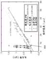
图8A是比较根据切换和非切换能量脉冲之间的脉冲数变化的电压降的说明性曲线图。图8B和8C是比较根据分别用于非切换电极组件和切换电极组件的脉冲宽度变化的电压降的说明性曲线图。8A is an illustrative graph comparing voltage drop as a function of pulse number between switched and non-switched energy pulses. 8B and 8C are illustrative graphs comparing voltage drop as a function of pulse width variation for non-switched electrode assemblies and switched electrode assemblies, respectively.
图9A是根据电压极性变化的脉冲数的说明性曲线图。图9B是根据切换和非切换能量脉冲之间的脉冲数变化的在电极组件处传送的能量的说明性曲线图。FIG. 9A is an explanatory graph of the number of pulses according to voltage polarity changes. 9B is an illustrative graph of energy delivered at an electrode assembly as a function of pulse number between switched and non-switched energy pulses.
具体实施方式Detailed ways
本文描述了包括一个或多个冲击波电极的装置和系统,所述冲击波电极可适用于血管成形术和/或瓣膜成形术。一般而言,冲击波电极沿着轴向延伸的细长构件(例如,导管)设置,并且可以附接到针对各种脉冲持续时间处于0.1kV至10kV的范围内的高压脉冲源上。在一些变型中,电极可以由运送导电流体(例如,盐水)的封罩围绕。在一些变型中,该封罩可包括围绕细长构件的一部分并且被配置为填充有导电流体的球囊,其中电极可以被封装在球囊壁内并与球囊壁间隔开。Described herein are devices and systems that include one or more shockwave electrodes that may be suitable for use in angioplasty and/or valvuloplasty. In general, shock wave electrodes are positioned along an axially extending elongated member (eg, a catheter) and can be attached to high voltage pulse sources in the range of 0.1 kV to 10 kV for various pulse durations. In some variations, the electrodes may be surrounded by an enclosure that carries a conductive fluid (eg, saline). In some variations, the enclosure can include a balloon surrounding a portion of the elongated member and configured to be filled with a conductive fluid, wherein the electrodes can be encapsulated within and spaced apart from the balloon wall.
控制器可以耦合到第一电极对以传送一系列能量脉冲,从而产生冲击波。所生成的冲击波可以破坏动脉或瓣膜中的钙化障碍物。下面描述冲击波形成的一种机制。当跨越位于导电流体内的一对电极施加高电压时,在它们之间可能形成等离子弧,从而在流体中产生蒸汽泡。当蒸汽泡首先形成时可能出现第一冲击波,而当蒸汽泡破裂时可能出现第二冲击波。冲击波可以经由流体被机械地传导以施加机械力或压力,从而破开脉管系统壁上或其中的任何钙化斑块。A controller may be coupled to the first electrode pair to deliver a series of energy pulses to generate shock waves. The resulting shock waves can destroy calcified obstructions in arteries or valves. One mechanism of shock wave formation is described below. When a high voltage is applied across a pair of electrodes located within a conductive fluid, a plasma arc may form between them, creating vapor bubbles in the fluid. A first shock wave may occur when the vapor bubble first forms, and a second shock wave may occur when the vapor bubble bursts. The shock wave can be mechanically conducted via the fluid to apply mechanical force or pressure to rupture any calcified plaque on or in the vasculature wall.
气泡的尺寸、膨胀率和塌缩(以及进而机械力的大小、持续时间和分布)可以基于电压脉冲的振幅和持续时间而变化。此外,气泡的时序和尺寸以及合成冲击波的声波输出和传播方向至少部分地取决于电极的位置、几何形状、尺寸、状态和电极之间的距离(电极间隙距离)。例如,电极间隙距离的增大会减少相应的声波输出。电极的尺寸和布置也会影响可以通过冲击波装置接近和治疗的血管结构的类型。冲击波电极可以由能够耐受在使用期间可能生成的高电压水平和强机械力(例如,在几微秒内约300-3000psi或20-200ATM)的材料制成。例如,电极可由不锈钢、钨、镍、铁、钢等制成。The size, expansion rate and collapse of the bubble (and thus the magnitude, duration and distribution of the mechanical force) can vary based on the amplitude and duration of the voltage pulse. Furthermore, the timing and size of the bubbles and the acoustic output and direction of propagation of the resultant shock wave depend, at least in part, on the location, geometry, size, state, and distance between electrodes (electrode gap distance). For example, an increase in the electrode gap distance reduces the corresponding acoustic output. The size and placement of the electrodes also affects the type of vascular structures that can be accessed and treated with the shock wave device. Shockwave electrodes can be made of materials that can withstand the high voltage levels and strong mechanical forces that may be generated during use (eg, about 300-3000 psi or 20-200 ATM in a few microseconds). For example, the electrodes may be made of stainless steel, tungsten, nickel, iron, steel, and the like.
一般而言,在导电流体中的一对电极之间流动的电流引起金属从正极端子移动到负极端子,最终耗尽正极端子材料,并且在电流流动方向固定时可称为单面腐蚀。由于流过流体的必要地高的电流(例如,数百安培)、由等离子弧产生的热量和机械冲击波力,冲击波电极会经历较高的磨损和腐蚀率。In general, current flowing between a pair of electrodes in a conductive fluid causes metal to move from the positive terminal to the negative terminal, eventually depleting the positive terminal material, and can be referred to as one-sided corrosion when the direction of current flow is fixed. Shockwave electrodes experience high wear and corrosion rates due to the necessarily high current (eg, hundreds of amps) flowing through the fluid, heat generated by the plasma arc, and mechanical shockwave forces.
本文描述的装置、系统和方法可有助于降低电极磨损率以增强电极耐久性和冲击波一致性。电极对的寿命可取决于以下中的至少一者:电压脉冲的极性、电压脉冲的长度、电压脉冲的大小、材料特性、流体传导率、电极对中的每个电极的导电区域之间的电极间隙距离、和/或该电极对中的电极的导电区域的表面积。与较短的脉冲相比,较长的脉冲可以增加电极对的磨损/腐蚀。在电极对具有不同尺寸的电极的一些变型中,其中一个电极具有比另一个电极更小的导电区域表面积,具有较小导电区域的电极会比具有较大导电区域的电极更容易受到腐蚀。也就是说,具有较小导电区域的电极腐蚀速率可以比具有较大导电区域的电极的腐蚀速率更快。本文描述的装置和方法可以有助于平衡电极对中的电极之间的腐蚀率,使得电极以大致相同的速率腐蚀。这可以增强整个电极对的耐久性,并且还可以促进在更大数量的脉冲上均匀地向电极对传送能量。The devices, systems, and methods described herein can help reduce electrode wear rates to enhance electrode durability and shock wave consistency. The lifetime of an electrode pair may depend on at least one of the following: polarity of the voltage pulse, length of the voltage pulse, magnitude of the voltage pulse, material properties, fluid conductivity, electrical conductivity between the conductive regions of each electrode in the electrode pair. The electrode gap distance, and/or the surface area of the conductive areas of the electrodes in the electrode pair. Longer pulses can increase wear/corrosion of the electrode pair compared to shorter pulses. In some variations of electrode pairs having electrodes of different sizes, where one electrode has a smaller conductive area surface area than the other electrode, the electrode with the smaller conductive area may be more susceptible to corrosion than the electrode with the larger conductive area. That is, electrodes with smaller conductive areas may corrode faster than electrodes with larger conductive areas. The devices and methods described herein can help balance the corrosion rate between electrodes in an electrode pair such that the electrodes corrode at approximately the same rate. This can enhance the durability of the entire electrode pair, and can also facilitate uniform energy delivery to the electrode pair over a larger number of pulses.
应当理解,当电极的尺寸不同并且其中较小的电极具有正极性而较大的电极具有负极性时,冲击波装置生成最强的冲击波。因此,虽然具有较小的正极端子电极和较大的负极端子电极的电极对可以形成最强的冲击波,但是这种尺寸和极性的组合会缩短电极对的寿命。寿命短的问题可能不是增加电极尺寸的简单事项,这是因为冲击波装置和电极的尺寸可能受到其被推进通过的脉管系统的尺寸限制。然而,如下面进一步详细描述的,电压极性切换可以促进电极寿命,同时保持电极尺寸,使得电极可以被导航通过脉管系统。附加地或替代地,电压极性切换可有利于在具有与非极性切换装置相似的电极寿命的情况下减小电极尺寸。It will be appreciated that the shock wave device generates the strongest shock waves when the electrodes are of different sizes and where the smaller electrodes have positive polarity and the larger electrodes have negative polarity. Therefore, while electrode pairs with smaller positive terminal electrodes and larger negative terminal electrodes can form the strongest shock waves, this combination of size and polarity can shorten the life of the electrode pairs. The issue of short lifetime may not be a simple matter of increasing electrode size, as the size of the shock wave device and electrode may be limited by the size of the vasculature through which it is propelled. However, as described in further detail below, voltage polarity switching can facilitate electrode longevity while maintaining electrode size so that the electrode can be navigated through the vasculature. Additionally or alternatively, voltage polarity switching may facilitate electrode size reduction with similar electrode lifetime as non-polar switching devices.
此外,本文描述的装置、系统和方法可促进形成在沿着冲击波装置的不同位置处的冲击波强度的均匀性。在一些变型中,冲击波装置可包括串联连接的多个间隔开的电极对。即使电极对的尺寸和形状相同,由电极对生成的冲击波的强度也可以变化。例如,彼此相隔180度定位的串联的相同电极对可从装置的相对两侧形成不同强度的冲击波。对于任何单个脉冲,这种差异可以忽略不计。然而,对于一系列脉冲,冲击波装置的一侧可能比装置的另一侧更有效地裂解钙沉积物。如下面进一步详细描述的电压极性切换可促进在不同电极对中形成的冲击波强度的均匀性。Furthermore, the devices, systems and methods described herein can promote uniformity of shock wave intensity formed at different locations along the shock wave device. In some variations, the shock wave device may include a plurality of spaced electrode pairs connected in series. The strength of the shock wave generated by the electrode pair can vary even if the electrode pair is the same size and shape. For example, identical electrode pairs in series positioned 180 degrees apart from each other can create shock waves of different intensities from opposite sides of the device. For any single pulse, this difference is negligible. However, for a series of pulses, one side of the shock wave device may break up calcium deposits more efficiently than the other side of the device. Voltage polarity switching, as described in further detail below, can promote uniformity of shock wave intensity formed in different electrode pairs.
例如,控制器可以使得对于一部分脉冲电流沿第一方向流过电极对,而对于另一部分脉冲电流沿与第一方向相反的第二方向流过电极对。作为示例,电流流动方向可以在每个脉冲或每两个脉冲之间变化,并且不受特别限制。应当指出,脉冲是离散地输出的,使得当电流未流过冲击波装置时脉冲之间存在时间间隔。可以根据例如冲击波产生的期望速率或频率来预先选择时间间隔的持续时间。此外,每个脉冲具有单一电流流动方向并且在脉冲内不切换。例如,电压极性切换可以仅在电流没有流向冲击波装置时切换(即,电压极性切换可以仅发生在电压脉冲之间的间隔中,而不发生在电压脉冲期间)。For example, the controller may cause the current to flow through the electrode pair in a first direction for a portion of the pulsed current and to flow through the electrode pair in a second direction opposite the first direction for another portion of the pulsed current. As an example, the current flow direction may vary between every pulse or every two pulses, and is not particularly limited. It should be noted that the pulses are output discretely so that there is a time interval between the pulses when current is not flowing through the shock wave device. The duration of the time interval may be pre-selected depending on, for example, the desired rate or frequency of shock wave generation. Furthermore, each pulse has a single current flow direction and does not switch within a pulse. For example, voltage polarity switching may only switch when current is not flowing to the shock wave device (ie, voltage polarity switching may only occur in the interval between voltage pulses, not during voltage pulses).
此外,对于每个脉冲,电流流动方向可以随机变化,只要脉冲的总数保持预定的电流流动方向比即可。例如,对于均匀分割为第一方向和第二方向的一组50个脉冲而言,不需要对于每个脉冲都切换电流流动方向。作为说明性示例,沿第一方向的20个脉冲之后可以跟随沿第二方向的10个脉冲,然后是沿第一方向的3个脉冲、沿第二方向的15个脉冲以及沿第一方向的2个脉冲。因此,虽然脉冲总数在第一和第二方向之间均匀地分割,但电流流动的切换次数不一定对应于电流流动比方向。Furthermore, for each pulse, the current flow direction can be changed randomly as long as the total number of pulses maintains a predetermined current flow direction ratio. For example, for a set of 50 pulses evenly divided into a first direction and a second direction, it is not necessary to switch the current flow direction for each pulse. As an illustrative example, 20 pulses in the first direction may be followed by 10 pulses in the second direction, then 3 pulses in the first direction, 15 pulses in the second direction, and 10 pulses in the
在一些变型中,可以在第二方向上提供单个脉冲,其余脉冲在第一方向上,反之亦然。相比于接收具有恒定极性的脉冲的电极对而言,这允许电极对在失效之前产生具有更多脉冲数的冲击波。因此,可以通过在两个电极上分配正脉冲的电极磨损/损耗来改善耐久性。In some variations, a single pulse may be provided in the second direction with the remaining pulses in the first direction, or vice versa. This allows the electrode pair to generate a shock wave with a higher number of pulses before failure than an electrode pair that receives pulses of constant polarity. Thus, durability can be improved by distributing the electrode wear/wear of the positive pulse across both electrodes.
在一个变型中,电流对于该系列中的大约一半脉冲可以沿第一方向流动,而对于该系列中的另外一半脉冲沿相反的第二方向流动。这样一来,对于大约一半的脉冲,每个电极被设置为正极端子,由此将任何一个电极所经历的高腐蚀正脉冲的数量大致相等地分布在该电极对的各电极之间。电流流动方向可以切换一次或多次。在一些情况下,电极对的寿命可以是具有单一电流流动方向的电极的大约两倍,从而允许形成更多的冲击波和/或形成比具有单一电流流动方向的电极更小的电极对。因此,本文描述的冲击波装置可能特别适用于诸如冠状动脉的小动脉。此外,包括多个电极对的冲击波装置可以促进由电极对生成的冲击波强度的均匀性,所述电极对具有在两个方向上都有电流流动的脉冲。In one variation, the current may flow in a first direction for about half of the pulses in the series and in the opposite second direction for the other half of the pulses in the series. In this way, for approximately half of the pulses, each electrode is set as the positive terminal, thereby distributing the number of high corrosion positive pulses experienced by any one electrode approximately equally between the electrodes of the electrode pair. The direction of current flow can be switched one or more times. In some cases, electrode pairs may last approximately twice as long as electrodes with a single current flow direction, allowing more shock waves to form and/or smaller electrode pairs than electrodes with a single current flow direction. Thus, the shock wave device described herein may be particularly useful in small arteries such as coronary arteries. Additionally, shock wave devices that include multiple electrode pairs can promote uniformity of shock wave intensity generated by electrode pairs having pulses with current flow in both directions.
I.装置I. Device
本文一般描述的是用于血管成形术和/或瓣膜成形术的冲击波装置。本文描述的装置和方法可使用在标题为“LOW PROFILE ELECTRODES FOR AN ANGIOPLASTY SHOCK WAVECATHETER(用于血管成形冲击波导管的低剖面电极)”的美国专利No.8,888,788中描述的一个或多个装置或元件和/或在标题为“SHOCK WAVE BALLOON CATHETER WITH MULTIPLESHOCK WAVE SOURCES(具有多个冲击波源的冲击波球囊导管)”的美国专利No.9,011,463中描述的一个或多个装置或元件,在此通过引用将各专利整体并入。Described generally herein are shock wave devices for angioplasty and/or valvuloplasty. The devices and methods described herein may use one or more of the devices or elements described in US Pat. No. 8,888,788 entitled "LOW PROFILE ELECTRODES FOR AN ANGIOPLASTY SHOCK WAVECATHETER" and and/or one or more of the devices or elements described in US Patent No. 9,011,463 entitled "SHOCK WAVE BALLOON CATHETER WITH MULTIPLESHOCK WAVE SOURCES", each of which is incorporated herein by reference The patent is incorporated in its entirety.
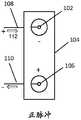
图1A是耦合到电极组件100的控制器120的框图。电极组件100可包括第一电极102、第二电极104和第三电极106。第一电极102可通过第一导线108连接到控制器120的电压源的第一电压输出端子V01,第三电极106可通过第二导线110连接到控制器120的电压源的第二电压输出端子V02,并且第二或公共电极104可串联设置在第一电极102与第三电极106之间。在施加足够的电压脉冲时,可以在第一电极102与第二电极104(即,第一电极对)之间形成第一等离子弧,并且可以在第二电极104与第三电极106(即,第二电极对)之间形成第二等离子弧。第一和第二电极对串联连接,其中第二电极104在第一和第二电极对之间共用。尽管以上将电极组件100描述为包括形成两个电极对的三个电极,但是电极组件的一些变型可包括形成一个电极对的两个电极。FIG. 1A is a block diagram of
能量脉冲的第一电流流动方向112可以通过控制器120的电压源122传送到电极组件100。控制器120可以使得传送到电极组件100的其它脉冲具有与第一方向112相反的第二电流流动方向116。对于传送到电极组件100的每个脉冲,控制器120可选择电流流动方向,并因此选择电极的电压极性。为了选择电流流动方向,控制器120可包括电压极性开关124,以在正极与负极之间切换电极102、106的极性,其中电极102、106具有相反的极性。The first
在一些变型中,对于一系列脉冲,控制器可以使得对于该系列中的一部分脉冲电流沿第一方向流过电极对,而对于该系列中的其余脉冲电流沿与第一方向相反的第二方向流过电极对。在一个变型中,可以为脉冲中的至少一个脉冲提供第一电流流动方向。在另一变型中,可以为至少约5%的脉冲提供第一电流流动方向。在另一变型中,可以为至少约10%的脉冲提供第一电流流动方向。在另一变型中,可以为至少约15%的脉冲提供第一电流流动方向。在另一变型中,可以为至少约20%的脉冲提供第一电流流动方向。在另一变型中,可以为至少约25%的脉冲提供第一电流流动方向。在另一变型中,可以为至少约30%的脉冲提供第一电流流动方向。在又一变型中,可以为至少约三分之一的脉冲提供第一电流流动方向。在另一变型中,可以为至少约40%的脉冲提供第一电流流动方向。在另一变型中,可以为至少约45%的脉冲提供第一电流流动方向。在再另一变型中,可以为至少约一半的脉冲提供第一电流流动方向。In some variations, for a series of pulses, the controller may cause current to flow through the electrode pair in a first direction for a portion of the series of pulses and in a second direction opposite the first direction for the remainder of the series of pulses flow through the electrode pair. In a variant, at least one of the pulses may be provided with a first current flow direction. In another variation, the first current flow direction may be provided for at least about 5% of the pulses. In another variation, the first current flow direction may be provided for at least about 10% of the pulses. In another variation, the first current flow direction may be provided for at least about 15% of the pulses. In another variation, the first current flow direction may be provided for at least about 20% of the pulses. In another variation, the first current flow direction may be provided for at least about 25% of the pulses. In another variation, the first current flow direction may be provided for at least about 30% of the pulses. In yet another variation, the first current flow direction may be provided for at least about one third of the pulses. In another variation, the first current flow direction may be provided for at least about 40% of the pulses. In another variation, the first current flow direction may be provided for at least about 45% of the pulses. In yet another variation, the first current flow direction may be provided for at least about half of the pulses.
在再另一些变型中,脉冲在第一方向上的电流流动与第二方向的比率可以是大约1:6。在另一变型中,脉冲在第一方向上的电流流动与第二方向的比率可以是大约5:6。在另一变型中,脉冲在第一方向上的电流流动与第二方向的比率可以是大约1:8。在另一变型中,脉冲在第一方向上的电流流动与第二方向的比率可以是大约3:8。在另一变型中,脉冲在第一方向上的电流流动与第二方向的比率可以是大约5:8。在另一变型中,脉冲在第一方向上的电流流动与第二方向的比率可以是大约7:8。在另一变型中,脉冲在第一方向上的电流流动与第二方向的比率可以是大约1:9。在另一变型中,脉冲在第一方向上的电流流动与第二方向的比率可以是大约2:9。在另一变型中,脉冲在第一方向上的电流流动与第二方向的比率可以是大约4:9。在另一变型中,脉冲在第一方向上的电流流动与第二方向的比率可以是大约5:9。在另一变型中,脉冲在第一方向上的电流流动与第二方向的比率可以是大约7:9。在另一变型中,脉冲在第一方向上的电流流动与第二方向的比率可以是大约8:9。在另一变型中,脉冲在第一方向上的电流流动与第二方向的比率可以是大约1:12。在另一变型中,脉冲在第一方向上的电流流动与第二方向的比率可以是大约1:16。在另一变型中,脉冲在第一方向上的电流流动与第二方向的比率可以是大约1:32。In still other variations, the ratio of current flow in the first direction to the second direction of the pulses may be about 1:6. In another variation, the ratio of current flow in the first direction to the second direction of the pulses may be approximately 5:6. In another variation, the ratio of the current flow of the pulses in the first direction to the second direction may be about 1:8. In another variation, the ratio of current flow in the first direction to the second direction of the pulses may be approximately 3:8. In another variation, the ratio of current flow in the first direction to the second direction of the pulses may be approximately 5:8. In another variation, the ratio of current flow in the first direction to the second direction of the pulses may be about 7:8. In another variation, the ratio of current flow in the first direction to the second direction of the pulses may be approximately 1:9. In another variation, the ratio of current flow in the first direction to the second direction of the pulses may be approximately 2:9. In another variation, the ratio of current flow in the first direction to the second direction of the pulses may be approximately 4:9. In another variation, the ratio of current flow in the first direction to the second direction of the pulses may be approximately 5:9. In another variation, the ratio of current flow in the first direction to the second direction of the pulses may be about 7:9. In another variation, the ratio of current flow in the first direction to the second direction of the pulses may be approximately 8:9. In another variation, the ratio of current flow in the first direction to the second direction of the pulses may be about 1:12. In another variation, the ratio of current flow in the first direction to the second direction of the pulses may be approximately 1:16. In another variation, the ratio of current flow in the first direction to the second direction of the pulses may be about 1:32.
应当理解的是,这些示例是非限制性的。例如,除了在第二方向上提供的一个脉冲之外,控制器可以针对每个脉冲提供沿第一方向的电流输送,反之亦然。每个电流流动方向上的脉冲数(例如,第一方向的电流流动与第二方向的比率)可以基于冲击波装置的期望寿命、冲击波均匀性、冲击波能量等来确定。在一些变型中,为大约一半脉冲提供第一电流流动方向可以使冲击波装置的寿命最大化。It should be understood that these examples are non-limiting. For example, the controller may provide current delivery in the first direction for each pulse in addition to one pulse provided in the second direction, and vice versa. The number of pulses in each current flow direction (eg, the ratio of current flow in the first direction to the second direction) may be determined based on the expected life of the shock wave device, shock wave uniformity, shock wave energy, and the like. In some variations, providing the first current flow direction for about half of the pulses may maximize the life of the shock wave device.
电流流动方向之间的转变次数没有特别限制。在一些情况下,可以根据第一方向上与第二方向上的脉冲的比率来切换电流流动方向。例如,当存在相等数量的正脉冲和负脉冲时,电流的方向可以针对每个脉冲转变。然而,对于每个脉冲,电流流动方向也可以随机变化,只要脉冲的总数保持预定的电流流动方向比即可。因此,即使每个方向上的脉冲数相等,电流流动方向也不需要针对每个脉冲切换。作为另一示例,平均交替脉冲的电流流动方向可以使较小电极的耐久性提高大约一倍,从而使电极组件的寿命提高大约一倍。即使当电极对中的电极具有相等尺寸时,交替电流流动方向以使得每个电极接收大约相同数量的正脉冲也将使磨损分布在两个电极上,从而使电极对的耐久性与接收单一电流方向的电极相比提高大约一倍。应当指出,任何数量的脉冲的极性切换均有助于耐久性(例如,电极在电极失效之前生成的冲击波的数量)。The number of transitions between current flow directions is not particularly limited. In some cases, the current flow direction may be switched according to the ratio of pulses in the first direction to the second direction. For example, when there are equal numbers of positive and negative pulses, the direction of the current flow can be switched for each pulse. However, the current flow direction may also vary randomly for each pulse, as long as the total number of pulses maintains a predetermined current flow direction ratio. Therefore, even if the number of pulses in each direction is equal, the current flow direction does not need to be switched for each pulse. As another example, the current flow direction of the average alternating pulses can approximately double the durability of smaller electrodes, thereby approximately doubling the life of the electrode assembly. Even when the electrodes in an electrode pair are of equal size, alternating the direction of current flow so that each electrode receives approximately the same number of positive pulses will distribute wear over both electrodes, making the electrode pair as durable as receiving a single current The direction of the electrode is approximately doubled compared to that of the electrode. It should be noted that polarity switching of any number of pulses contributes to durability (eg, the number of shock waves generated by the electrode before the electrode fails).
此外,由于极性切换允许每个电极对接收正脉冲,因此从不同电极对输出的冲击波平均起来可以促进冲击波位置之间的冲击波力的均匀性。这允许更易预测的结果:其中在每个冲击波位置处传送更高的平均冲击波强度。例如,图9B是根据静态(恒定极性)冲击波装置和切换(交替极性)冲击波装置的脉冲数输送的能量的说明性曲线图。在图9B中,与输送到恒定极性装置的能量相比,由极性切换冲击波装置输送的电能平均下来每个脉冲更高,并且衰减更小。输送的电能可与冲击波强度正相关。Furthermore, since the polarity switching allows each electrode pair to receive a positive pulse, the shock waves output from different electrode pairs, averaged, can promote uniformity of shock wave force between shock wave locations. This allows for more predictable results: where a higher average shock wave intensity is delivered at each shock wave location. For example, FIG. 9B is an illustrative graph of energy delivered as a function of the number of pulses for a static (constant polarity) shockwave device and a switched (alternating polarity) shockwave device. In Figure 9B, the power delivered by the polarity-switching shock wave device is on average higher per pulse and less attenuated than the power delivered to the constant polarity device. The delivered electrical energy may be positively related to the shock wave intensity.
接下来,图1B和1C中所示的第二电极104可具有筒形(圆柱形)或环形形状,类似于如下面进一步详细讨论的图6C中所示的形状。然而,为了便于解释,图1B和1C描绘了扁平的第二电极104,以说明可以施加至电极组件100的不同电压极性。在图1B中,控制器120可以在第一电流流动方向112上输出一个或多个正脉冲,其中第一导线108耦合到控制器120的电压源122的正极端子和第一电极102,并且第二导线110耦合到控制器120的电压源的负极端子和第三电极106。在使用中,施加电压脉冲在流体中产生等离子体,该等离子体延伸穿过电极对并允许电流传导。然后电流从第一电极102流到第二电极104,然后流到第三电极106。因此,等离子体形成产生了两个串联连接的电极对。如上所述,当从控制器120接收正脉冲时,正极端子的第一电极102可能经历比负极端子的第三电极106更高的磨损率。Next, the
相反,在图1C中,当从控制器120的电压源122接收在第二电流流动方向116上的负脉冲时,负极端子的第一电极102可以消耗比正极端子的第三电极106更少的材料。为了更均匀地分布第一电极102与第三电极106之间的磨损,控制器120可以使得对于一部分脉冲电流沿第一方向112流动(图1B)并且对于其它脉冲电流沿与第一方向112相反的第二方向116流动(图1C)。结果,在一个或两个较小电极(102,106)耗尽并且电极组件100失效之前,电极组件100可形成更大数量的具有改善的一致性的冲击波。Conversely, in FIG. 1C, when receiving a negative pulse in the second
此外,如图1B和1C所示,无论电流流动方向如何,第一电极102和第三电极106都将具有相反的电压极性。因此,由第一电极对和第二电极对形成的冲击波的强度对于每个脉冲将不同。在图示的实施例中,第一电极102和第三电极106的导电区域可以小于第二电极104的导电区域。因此,接收正脉冲112(图1B)的第一电极对可以生成比第二电极对更强的冲击波。类似地,接收负脉冲116的第一电极对可以生成比第二电极对更弱的冲击波。Furthermore, as shown in Figures IB and 1C, regardless of the direction of current flow, the
然而,通过将正脉冲和负脉冲交替到电极组件100,由第一电极对和第二电极对输出的平均冲击波强度可以更均,从而减小变化性。这可以通过冲击波装置提供更一致和可预测的处理,使得实际工作者可以不需要基于电极对之间的冲击波强度的差异来将脉管系统中的冲击波装置对准。However, by alternating positive and negative pulses to the
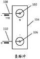
图1D是耦合到电极组件100的控制器120的另一变型的框图。电极组件100可包括第一电极102、第二电极104和第三电极106。第一电极102和第二或公共电极104形成第一电极对,第三电极106和第二电极104形成第二电极对。能量脉冲的第一电流流动方向112可以通过控制器120的电压源122传递到电极组件100。控制器120可以使得输送到电极组件100的其它脉冲具有与通过电极组件100的第一方向112相反的第二电流流动方向116。对于传送到电极组件100的每个脉冲,控制器120的电压极性开关124可选择电流流动方向,并因此选择电极的电压极性。FIG. ID is a block diagram of another variation of the
在图1D中,第一电极102可通过第一导线108连接到控制器120的电压源122的第一电压输出端子V01,第三电极106可通过第二导线110连接到控制器120的电压源122的第二电压输出端子V02,并且第二电极104可通过第三导线114连接到控制器120的电压源122的第三电压输出端子V03(接地通道)。在一些变型中,对于一部分脉冲,第一电压输出端子V01和第二电压输出端子V02可以是正通道,而第三电压输出端子V03可以是负通道。对于其余脉冲,控制器120也可以将第一电压输出端子V01和第二电压输出端子V02设置为负通道,而第三电压输出端子V03可以是正通道。In FIG. 1D , the
在第一和/或第二电压输出端子V01、V02上的高电压脉冲期间,电流可沿第一方向112或第二方向116经第一导线108和/或第二导线110流到相应的第一电极102和第三电极106。控制器120的电压源122可以在输出端子V01上施加正或负脉冲,使得第一电极102与第二电极104之间的电位差足够大以在它们之间形成等离子弧,从而产生气泡,该气泡产生冲击波。类似地,控制器120的电压源122可以在输出端子V02上同时或依次施加正或负脉冲,使得第三电极106与第二电极104之间的电位差足够大以在它们之间形成等离子弧,从而产生气泡,该气泡产生不同的冲击波。在一些变型中,当能量脉冲同时施加至输出端子V01和V02时,可以同时形成在第一电极102与第二电极104之间形成的第一冲击波和在第三电极106与第二电极104之间形成的第二冲击波。During the high voltage pulses on the first and/or second voltage output terminals V01, V02, current may flow in the
在第一电极102和第三电极106彼此在周向上相对地定位(例如,围绕细长构件的圆周彼此间隔180度)的情况下,由第一和第二电极对生成的冲击波可以在从冲击波装置的两侧向外延伸的相反方向上传播。穿过气泡从第一电极102和/或第三电极106到达第二电极104的电流可经由第三导线114返回到电压输出端子V03(其可以是接地通道)。电压输出端子V01和V02可以被独立地寻址(例如,电压和电流可以施加至一个输出端但不一定施加至另一输出端),或者可以不被独立地寻址(例如,激活一个输出端必然激活另一输出端)。With the
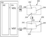
在另一变型中,图2A是耦合到第一和第二电极组件200、250的控制器220的框图。第一电极202和第一公共电极206形成可生成第一冲击波的第一电极对,并且第二电极204和第一公共电极206形成可生成第二冲击波的第二电极对。同样,第三电极252和第二公共电极256形成可生成第三冲击波的第三电极对,并且第四电极254和第二公共电极256形成可生成第四冲击波的第四电极对。In another variation, FIG. 2A is a block diagram of a
第一、第二、第三和第四电极对可以以串联构型连接并接收一系列脉冲。该系列中的一部分脉冲的第一电流流动方向214可通过控制器220的电压源222传送到第一和第二电极组件200、250。控制器220可以使得输送到第一和第二电极组件200、250的该系列中的剩余脉冲具有通过电极组件200、250的第二电流流动方向216。对于传送到电极组件200、250的每个脉冲,控制器220的电压极性开关224可选择电流流动方向,并因此选择电极的电压极性。例如,电压极性开关224可将第一电极202和第四电极254的极性在正和负之间切换,其中第一电极202和第四电极254具有相反的极性。The first, second, third and fourth electrode pairs may be connected in a series configuration and receive a series of pulses. The first
在一些变型中,对于一系列脉冲,控制器可以使得对于该系列中的一部分脉冲电流沿第一方向流过电极对,而对于该系列中的其余脉冲电流沿与第一方向相反的第二方向流过电极对。在一个变型中,可以为脉冲中的至少一个脉冲提供第一电流流动方向。在另一变型中,可以为至少约5%的脉冲提供第一电流流动方向。在另一变型中,可以为至少约10%的脉冲提供第一电流流动方向。在另一变型中,可以为至少约15%的脉冲提供第一电流流动方向。在另一变型中,可以为至少约20%的脉冲提供第一电流流动方向。在另一变型中,可以为至少约25%的脉冲提供第一电流流动方向。在另一变型中,可以为至少约30%的脉冲提供第一电流流动方向。在又一变型中,可以为至少约三分之一的脉冲提供第一电流流动方向。在另一变型中,可以为至少约40%的脉冲提供第一电流流动方向。在另一变型中,可以为至少约45%的脉冲提供第一电流流动方向。在再另一变型中,可以为至少约一半的脉冲提供第一电流流动方向。In some variations, for a series of pulses, the controller may cause current to flow through the electrode pair in a first direction for a portion of the series of pulses and in a second direction opposite the first direction for the remainder of the series of pulses flow through the electrode pair. In a variant, at least one of the pulses may be provided with a first current flow direction. In another variation, the first current flow direction may be provided for at least about 5% of the pulses. In another variation, the first current flow direction may be provided for at least about 10% of the pulses. In another variation, the first current flow direction may be provided for at least about 15% of the pulses. In another variation, the first current flow direction may be provided for at least about 20% of the pulses. In another variation, the first current flow direction may be provided for at least about 25% of the pulses. In another variation, the first current flow direction may be provided for at least about 30% of the pulses. In yet another variation, the first current flow direction may be provided for at least about one third of the pulses. In another variation, the first current flow direction may be provided for at least about 40% of the pulses. In another variation, the first current flow direction may be provided for at least about 45% of the pulses. In yet another variation, the first current flow direction may be provided for at least about half of the pulses.
在再另一些变型中,脉冲在第一方向上的电流流动与第二方向的比率可以是大约1:6。在另一变型中,脉冲在第一方向上的电流流动与第二方向的比率可以是大约5:6。在另一变型中,脉冲在第一方向上的电流流动与第二方向的比率可以是大约1:8。在另一变型中,脉冲在第一方向上的电流流动与第二方向的比率可以是大约3:8。在另一变型中,脉冲在第一方向上的电流流动与第二方向的比率可以是大约5:8。在另一变型中,脉冲在第一方向上的电流流动与第二方向的比率可以是大约7:8。在另一变型中,脉冲在第一方向上的电流流动与第二方向的比率可以是大约1:9。在另一变型中,脉冲在第一方向上的电流流动与第二方向的比率可以是大约2:9。在另一变型中,脉冲在第一方向上的电流流动与第二方向的比率可以是大约4:9。在另一变型中,脉冲在第一方向上的电流流动与第二方向的比率可以是大约5:9。在另一变型中,脉冲在第一方向上的电流流动与第二方向的比率可以是大约7:9。在另一变型中,脉冲在第一方向上的电流流动与第二方向的比率可以是大约8:9。在另一变型中,脉冲在第一方向上的电流流动与第二方向的比率可以是大约1:12。在另一变型中,脉冲在第一方向上的电流流动与第二方向的比率可以是大约1:16。在另一变型中,脉冲在第一方向上的电流流动与第二方向的比率可以是大约1:32。In still other variations, the ratio of current flow in the first direction to the second direction of the pulses may be about 1:6. In another variation, the ratio of current flow in the first direction to the second direction of the pulses may be about 5:6. In another variation, the ratio of the current flow of the pulses in the first direction to the second direction may be about 1:8. In another variation, the ratio of current flow in the first direction to the second direction of the pulses may be approximately 3:8. In another variation, the ratio of current flow in the first direction to the second direction of the pulses may be about 5:8. In another variation, the ratio of current flow in the first direction to the second direction of the pulses may be about 7:8. In another variation, the ratio of current flow in the first direction to the second direction of the pulses may be approximately 1:9. In another variation, the ratio of current flow in the first direction to the second direction of the pulses may be approximately 2:9. In another variation, the ratio of current flow in the first direction to the second direction of the pulses may be approximately 4:9. In another variation, the ratio of current flow in the first direction to the second direction of the pulses may be approximately 5:9. In another variation, the ratio of current flow in the first direction to the second direction of the pulses may be about 7:9. In another variation, the ratio of current flow in the first direction to the second direction of the pulses may be approximately 8:9. In another variation, the ratio of current flow in the first direction to the second direction of the pulses may be about 1:12. In another variation, the ratio of current flow in the first direction to the second direction of the pulses may be approximately 1:16. In another variation, the ratio of current flow in the first direction to the second direction of the pulses may be about 1:32.
在一些变型中,每个电流流动方向上的脉冲数(例如,第一方向的电流流动与第二方向的比率)可以基于冲击波装置的期望寿命、冲击波均匀性、冲击波能量、材料特性、电极间隙距离、流体传导率等来确定。在一些情况下,可以根据第一方向上与第二方向上的脉冲的比率来切换电流流动方向。在另一些情况下,对于每个脉冲,电流流动方向可以随机变化,只要脉冲的总数保持预定的电流流动方向比即可。In some variations, the number of pulses in each current flow direction (eg, the ratio of current flow in the first direction to the second direction) may be based on the expected life of the shock wave device, shock wave uniformity, shock wave energy, material properties, electrode gap distance, fluid conductivity, etc. In some cases, the current flow direction may be switched according to the ratio of pulses in the first direction to the second direction. In other cases, the current flow direction can be randomly varied for each pulse, as long as the total number of pulses maintains a predetermined current flow direction ratio.
此外,从第一至第四电极对输出的冲击波平均起来可具有更均匀的强度,因为极性切换允许每个电极对接收正脉冲。这允许更易预测的结果,其中向每个电极对输送更大量的电能,这可以促进更强冲击波的生成。因此,无论冲击波装置在脉管系统内的取向如何,冲击波装置都能够更均匀地施加机械力/压力。Furthermore, the shock waves output from the first to fourth electrode pairs may have, on average, a more uniform intensity because the polarity switching allows each electrode pair to receive a positive pulse. This allows for more predictable results, where a greater amount of electrical energy is delivered to each electrode pair, which can facilitate the generation of stronger shock waves. Thus, the shock wave device is able to apply mechanical force/pressure more uniformly regardless of its orientation within the vasculature.
在一些变型中,图2A所示的第一和第二公共电极206、256可具有筒形或环形形状,类似于如下面进一步详细讨论的图6C中所示的形状。然而,为了便于说明,图2B描绘了扁平的第一和第二公共电极206、256,以图示可以施加至第一和第二电极组件200、250的不同电压极性。控制器220的电压源222可输出一个或多个脉冲,其中第一导线208耦合到控制器220的正极端子V01,并且第三导线212耦合到控制器220的负极端子V02。第二电极204可经由第二导线210(例如,互连导线)连接到第三电极252。在该构型中,第一和第二电极组件200、250接收正脉冲,其中第一和第三电极对生成比第二和第四电极对更强的冲击波。In some variations, the first and second
相反地,控制器220的电压源222可输出一个或多个脉冲,其中第一导线208耦合到控制器220的负极端子V01,并且第三导线212耦合到控制器220的正极端子V02。在该构型中,第一和第二电极组件200、250接收负脉冲,其中第二和第四电极对生成较强的冲击波。因此,为了更均匀地分布第一和第二电极组件200、250的电极之间的磨损,控制器220的电压极性开关224可以使得电流对于一系列脉冲中的一部分脉冲沿第一方向流动并且对于该系列中的其余脉冲沿与第一方向相反的第二方向流动。结果,电极组件200、250可以在一个或多个较小的内部电极(202,204,252,254)耗尽之前形成更多数量的冲击波,以及从电极组件(200,250)平均传播的更均匀冲击波。Conversely, the
图3是冲击波系统300的一个变型的说明性框图,冲击波系统300包括第一电极组件302、第二电极组件303、第三电极组件304、第四电极组件306和第五电极组件307。第一电极组件302可包括第一电极302a、第二电极302b和第三电极302c,其分别具有类似于如图1A和1B所示的第一电极102、第二电极104和第三电极106的结构。如图3中象征性地表示,第一电极302a和第三电极302c的导电表面积可以比第二电极302b的导电表面积小。在另一些变型中,较大电极302b可包括通过例如互连导线连接的单独电极。第二至第五电极组件303、304、306和307可包括与第一电极组件302类似的电极构型。3 is an illustrative block diagram of one variation of a
第一和第二电极组件302和303串联连接。第四和第五电极组件306、307串联连接。如图3所示,电极组件302、303、304、306和307可切换地与控制器310并联连接。控制器310可包括电压源312,以将脉冲传递到电极组件302、303、304、306和307。控制器310的多路复用器316可选择性地激活第一和第二电极组件302和303、第三电极组件304以及第四和第五电极组件306和307。多路复用器316可被配置为单独地、一次一个地或以任何组合选择性地跨越并联的电极组件线路连接电压源312。控制器310还可以包括电压极性开关314,其被配置为提供与第一开关位置318相对应的第一电流流动方向和与第一方向相反的第二电流流动方向,第二方向对应于第二开关位置320。The first and
例如,电压源312将预定的电压脉冲输出到电压极性开关314。在开关314中,在第一电流流动方向和与第一方向相反的第二方向之间选择电流流动方向。多路复用器316可以在第一方向或第二方向上接收能量脉冲,然后选择性地将具有由电压极性开关314选择的电流流动方向的一系列脉冲传送到电极组件302、303、304、306和307,如图4的时序图所示。For example,
图4是用于以选择性的电流传送方向选择性地将电极耦合到电源的冲击波系统300的一个变型的说明性时序图。例如,控制器310可以以第一电压极性依次地(例如,一次一个地)激活不同组的电极组件,然后以第二电压极性依次地激活不同组的电极组件。这为各冲击波保存了全部高电压,从而形成要施加至沿整个脉管系统的钙沉淀物的最大强度的冲击波。针对每个电极组件302、303、304、306和307在后续脉冲中反转极性可以在电极组件的电极对内更均匀地分配电极磨损和冲击波强度,从而提高冲击波装置的寿命和一致性。在另一些示例中,电极组件的电压极性可以对每个脉冲、每隔两个脉冲、每隔三个脉冲进行变化,并且不受特别限制。此外,电压极性可随机变化。例如,对于在第一电压极性(例如,正脉冲)与第二电压极性(例如,负脉冲)之间均匀地分割的一组50个脉冲,电压极性不需要针对每个脉冲进行切换。作为说明性示例,第一电压极性下的8个脉冲之后可以跟随第二电压极性下的5个脉冲,然后是第一电压极性下的7个脉冲、第二电压极性下的5个脉冲、第一电压极性下的10个脉冲以及第二电压极性下的15个脉冲。因此,虽然脉冲总数在第一和第二电压极性之间均匀地分割,但极性的切换次数不一定对应于/依赖于电流流动比。4 is an illustrative timing diagram of one variation of a
在一些变型中,多路复用器可耦合到电极组件302、303、304、306和307中的一个或多个,如图3所示。例如,本文讨论的任何电压极性切换顺序均可与多路复用器316合并。在一些变型中,电压极性的选择可以与通过多路复用器选择的电极组件无关。交替的极性和时序可提供在多个电极上分配正脉冲磨损和增加电极组件的休息时间的双重益处。In some variations, a multiplexer may be coupled to one or more of
上述极性切换和多路复用可以应用于本文描述的任何冲击波装置,包括如下面详细描述的图5-7B的说明性变型。在一个变型中,描述了具有多个电极组件的冲击波装置。特别地,图5描绘了具有两个电极组件506、508的冲击波装置的远侧部分。特别地,图5描绘了冲击波装置500的一个变型,冲击波装置500包括细长构件502、在沿细长构件502的长度的第一位置处的第一电极组件506、在沿细长构件502的长度的第二位置处的第二电极组件508以及可选的封罩504,所述封罩504被配置为可填充有导电流体以可密封地封装第一和第二电极组件506、508。在一些变型中,封罩可包括膜和/或球囊,其可由电绝缘材料制成,该电绝缘材料可以是非顺应性的(例如,PET等)、半顺应性的(例如,PBAX、尼龙、PEBA、聚乙烯等)和/或顺应性的(例如聚氨酯、硅树脂等)。封罩504可封装任何数量的电极组件。The above-described polarity switching and multiplexing can be applied to any of the shock wave devices described herein, including the illustrative variations of FIGS. 5-7B as described in detail below. In one variation, a shock wave device having multiple electrode assemblies is described. In particular, FIG. 5 depicts a distal portion of a shock wave device having two
冲击波装置500可包括流体内腔(未示出),该流体内腔与将导电流体引入封罩506中的流体源连通。具有第一端子510和第二端子512的电压源(未示出)可以耦合到冲击波装置500。如上所述,端子510、512的极性可以每脉冲或以预定序列变化。能量脉冲可以施加到电极对506、508,由此产生一个或多个冲击波,该冲击波可通过流体传播以撞击钙化障碍物。尽管图5中的冲击波装置500被描绘为具有两个电极对506、508,但是应当理解,其它变型也可具有不同数量的电极对(例如,3、4、5、6或更多个电极对)。
在一些变型中,电极组件506、508各自都可包括两个彼此在周向上相对地定位的内电极、具有在两个内电极上对准的两个开口的绝缘护套、以及具有与绝缘护套的两个开口同轴对准的两个开口的外公共电极。图6A-6C示出了这种构型下的电极组件的一个变型,该电极组件包括两个内电极和一个外公共电极。每个电极组件506、508可以被配置为生成一对定向冲击波,其中到达第一内电极的由高电压脉冲产生的冲击波在与到达第二内电极的由高电压脉冲产生的冲击波的方向相反的方向上传播。在一些变型中,电极组件506、508可生成冲击波,这些冲击波从细长构件502的圆周周围的不同位置向外传播。例如,电极组件506可生成从细长构件的左右纵向两侧传播的冲击波,而电极组件508可生成从细长构件502的上下纵向两侧传播的冲击波。In some variations, each of the
在另一些变型中,电极组件506可生成一对从细长构件502的圆周周围的0度和180度位置向外传播的冲击波,而电极组件508可生成一对从细长构件的圆周周围的60度和240度的位置向外传播的冲击波。在再另一些变型中,电极组件506、508可各自生成一对在细长构件的圆周周围的相同位置处但从沿着细长构件的长度的不同位置向外传播的冲击波。可选地,可沿细长构件的长度设置一个或多个不透射线的标记带,以允许实际工作者在冲击波装置500插入穿过患者的脉管系统时识别它的位置和/或取向。In other variations,
应当理解,具有沿着导管长度分布的多个电极组件的冲击波装置可适用于血管成形术以破坏可沿着血管长度定位的钙化斑块。具有沿着弯曲的细长构件的长度的多个电极组件的冲击波装置可适用于瓣膜成形术以破坏可位于瓣膜的圆周周围(例如,瓣膜的小叶处或其周围)的钙化斑块。应当指出,当电极组件506、508各自都包括如图6所示的两个电极对时,图2A的电路图和图2B的简化布局在电气上对应于图5的实施例。It will be appreciated that a shock wave device having multiple electrode assemblies distributed along the length of the catheter may be suitable for use in angioplasty to disrupt calcified plaque that may be located along the length of the vessel. A shock wave device having multiple electrode assemblies along the length of the curved elongated member may be suitable for use in valvuloplasty to destroy calcified plaque that may be located around the circumference of the valve (eg, at or around the leaflets of the valve). It should be noted that the circuit diagram of FIG. 2A and the simplified layout of FIG. 2B correspond electrically to the embodiment of FIG. 5 when the
图6A-6B分别描绘了具有电极组件600的冲击波装置的一个变型的顶视图和底视图,该电极组件600可以被配置为生成沿相反方向的冲击波。图6A是电极组件600的顶视图,其中示出了第一内电极602,图6B是电极组件600的底视图,其中示出了第二内电极604。第一和第二内电极共用公共电极606并且彼此在周向上相对地定位(即,隔开180度)。第一电极602可以通过第一导线608连接到控制器(图6A-6B中未示出)的电压源的第一电压输出端子V01,并且第二电极604可以通过第二导线610连接到控制器的电压源的第二电压输出端子V02。第一电极602和公共电极606形成第一电极对,其可生成在第一冲击波方向上向外传播的第一冲击波,并且第二电极604和公共电极606形成第二电极对,其可生成在与第一冲击波方向相反的第二冲击波方向上向外传播的第二冲击波。对于在第一电流方向616上提供的正脉冲,电流从第一电极对流到第二电极对。同样,对于在与第一电流方向616相反的第二电流方向618上提供的负脉冲,电流从第二电极对流到第一电极对。6A-6B depict top and bottom views, respectively, of a variation of a shock wave device having an
可以提供电极对内的导电区域的表面积的差异以生成更大的冲击波。例如,第一电极602和第二电极604的边缘的表面积可用作导电区域,并且可以是电极的由于高能量脉冲而最容易磨损的部分。诸如公共电极606的电极可以针对具有不同表面积的第一和第二电极602、604中的每一个形成两个导电区域。在一些变型中,第一电极602和第二电极604的导电区域的表面积可以比公共电极606的表面积小。因此,电极组件600的寿命可取决于较小电极602、604的消耗率。Differences in the surface area of the conductive regions within the electrode pairs can be provided to generate larger shock waves. For example, the surface areas of the edges of the
当能量脉冲施加至电极对以形成冲击波时,来自内电极和外电极的电极材料的腐蚀可以增加电极对中的各电极之间的距离,直至不再可能形成等离子弧。此时,电极对已经失效并达到其使用寿命。如下面进一步详细讨论的,可以通过测量电压降、电压脉冲宽度、电压脉冲宽度的低电压模拟和/或指示电极对两侧的高电压脉冲的持续时间(或与之相关)的任何信号中的一者或多者来确定腐蚀和磨损程度。When energy pulses are applied to the electrode pair to form a shock wave, corrosion of the electrode material from the inner and outer electrodes can increase the distance between the electrodes in the electrode pair until a plasma arc is no longer possible. At this point, the electrode pair has failed and reached its useful life. As discussed in further detail below, this can be accomplished by measuring voltage drop, voltage pulse width, low voltage simulation of voltage pulse width, and/or any signal indicative of the duration of (or related to) high voltage pulses across the electrode pair. one or more to determine the degree of corrosion and wear.
图6C描绘了外公共电极606的透视图。如其中所示,第一开口612可直接定位在第二开口614对面。外公共电极606可具有在第二内电极上同轴对准的第二开口614,并且第一内电极604可以与外公共电极606的第一开口612同轴对准。此构型可生成在第一方向上向外传播的第一冲击波和在与第一方向相反的第二方向上向外传播的第二冲击波。FIG. 6C depicts a perspective view of the outer
回到图6A和6B,导线608、610可以沿着其长度电绝缘(例如,通过由例如聚酰亚胺、PEBA、PET、FEP、PTFE等制成的绝缘涂层或护套),其中导线的导电芯露出以接触内电极和/或外电极的一部分的一个或多个区域除外。导线608、610可由任何导电材料制成,例如,无氧铜或铜或银。Returning to Figures 6A and 6B, the
图7A-7B描绘了具有第一电极组件700和第二电极组件750的冲击波装置的一个变型的顶视图和底视图,第一电极组件700和第二电极组件750可以被配置为沿着冲击波装置的长度生成冲击波。电极组件700、750可以相对于彼此串联连接,使得激活第一电极组件700也激活了第二电极组件750。在一些变型中,可能希望具有多个冲击波源而没有尽可能多的导线并且在控制器上使用较少的端子。例如,将两个电极组件串联连接可允许冲击波装置仅使用两个电压输出端子(例如,一个正通道和一个负通道)同时产生多达四个不同的冲击波。另外,减少沿着细长构件的长度延伸的导线的数量可允许细长构件在其被推进通过患者的脉管系统时更自由地弯曲和收缩(例如,可以允许更小的转弯半径)。7A-7B depict top and bottom views of one variation of a shock wave device having a
图7A是电极组件700、750的顶视图,其中描绘了第一内电极706和第四内电极754。图7B是电极组件700、750的底视图,其中示出了第二内电极704和第三内电极752。第一和第二内电极702、704共用第一公共电极706并且彼此在周向上相对地定位(即,隔开180度)。第三和第四内电极752、754共用第二公共电极756并且还彼此在周向上相对地定位。或者,内电极和电极组件可以以如上所述的某些其它方式彼此偏移。Figure 7A is a top view of the
第一电极702和第一公共电极706形成第一电极对,其可生成在第一冲击波方向上向外传播的第一冲击波,并且第二电极704和第一公共电极706形成第二电极对,其可生成在第二方向上向外传播的第二冲击波。同样,第三电极752和第二公共电极756形成可生成在第三方向上向外传播的第三冲击波的第三电极对,并且第四电极754和第二公共电极756形成可生成在第四方向上向外传播的第四冲击波的第四电极对。The
图7A-7B中的第一和第二电极组件700、750可串联连接。第一电极702可通过第一导线708连接到控制器的电压源的第一电压输出端子V01(图7A-7B中未示出)。第二电极704可经由第二导线710(例如,互连导线)连接到第三电极752。第四电极754可通过第三导线712连接到控制器的电压源的第二电压输出端子V02。因此,对于在第一电流方向714上提供的正脉冲,电流从第一电极对(按升序)流到第四电极对。同样,对于在与第一电流方向714相反的第二电流方向716上提供的负脉冲,电流从第四电极对(按降序)流到第一电极对。第一至第四电极702、704、752、754中的每一者的尺寸可小于第一和第二公共电极706、756。在一些变型中,尺寸可以指电极的总尺寸和/或电极的导电区域的表面积。因此,电极组件700、750的寿命可取决于较小电极702、704、752、754的消耗率。The first and
本文描述的任何冲击波装置可以设置在适用于血管成形术或瓣膜成形术的冲击波系统中。冲击波系统(未示出)可包括冲击波装置、导管、高电压脉冲发生器(例如,电压源)和/或被配置为可填充有导电流体的封罩。导管可具有穿过其中的导线内腔。在一些变型中,高压脉冲发生器可以是0.1kV至10kV的脉冲电源,例如,2kV至6kV的脉冲电源。Any of the shock wave devices described herein may be provided in a shock wave system suitable for use in angioplasty or valvuloplasty. A shock wave system (not shown) may include a shock wave device, a conduit, a high voltage pulse generator (eg, a voltage source), and/or an enclosure configured to be filled with a conductive fluid. The catheter may have a guidewire lumen therethrough. In some variations, the high voltage pulse generator may be a 0.1 kV to 10 kV pulsed power source, eg, a 2kV to 6 kV pulsed power source.
II.方法II. Methods
本文大体上描述了用于形成冲击波的方法。本文描述的任何冲击波装置可用于血管成形术和/或瓣膜成形术。本文描述的方法可包括将导丝从患者的进入部位(例如,腿的腹股沟区域中的动脉)推进到血管的目标区域(例如,具有需要被破坏的钙化斑块的区域)。冲击波装置可包括具有导丝内腔的轴向延伸的细长构件、包括第一电极和第二电极的电极对和/或沿着细长构件的长度设置的电极组件。电极对和/或电极组件可以是本文描述的任何电极。Methods for forming shock waves are generally described herein. Any of the shock wave devices described herein can be used in angioplasty and/or valvuloplasty. The methods described herein can include advancing a guidewire from a patient's access site (eg, an artery in the groin region of the leg) to a target area of the blood vessel (eg, an area with calcified plaque that needs to be destroyed). The shock wave device may include an axially extending elongated member having a guidewire lumen, an electrode pair including a first electrode and a second electrode, and/or an electrode assembly disposed along the length of the elongated member. The electrode pair and/or electrode assembly can be any electrode described herein.
在一些变型中,当装置被推进通过脉管系统时,球囊可以塌缩在细长构件上。在一些变型中,冲击波装置的位置可以通过X射线成像和/或荧光透视来确定。当冲击波装置到达目标区域时,可以用导电流体(例如,盐水和/或与造影剂混合的盐水)填充球囊。例如,可以将一系列脉冲输送到第一电极对和/或电极组件以产生可以破坏钙化斑块的冲击波。In some variations, the balloon may collapse on the elongated member as the device is advanced through the vasculature. In some variations, the location of the shock wave device may be determined by X-ray imaging and/or fluoroscopy. When the shock wave device reaches the target area, the balloon can be filled with a conductive fluid (eg, saline and/or saline mixed with a contrast agent). For example, a series of pulses can be delivered to the first electrode pair and/or electrode assembly to generate shock waves that can disrupt calcified plaque.
在一些变型中,电流对于该系列中的一部分脉冲沿第一方向流过电极对和/或电极组件,而对于该系列中的其余脉冲沿与第一方向相反的第二方向流过电极对和/或电极组件。在一个变型中,可以为脉冲中的至少一个脉冲提供第一电流流动方向。在另一变型中,可以为至少约5%的脉冲提供第一电流流动方向。在另一变型中,可以为至少约10%的脉冲提供第一电流流动方向。在另一变型中,可以为至少约15%的脉冲提供第一电流流动方向。在另一变型中,可以为至少约20%的脉冲提供第一电流流动方向。在另一变型中,可以为至少约25%的脉冲提供第一电流流动方向。在另一变型中,可以为至少约30%的脉冲提供第一电流流动方向。在又一变型中,可以为至少约三分之一的脉冲提供第一电流流动方向。在另一变型中,可以为至少约40%的脉冲提供第一电流流动方向。在另一变型中,可以为至少约45%的脉冲提供第一电流流动方向。在再另一变型中,可以为至少约一半的脉冲提供第一电流流动方向。In some variations, current flows through the electrode pairs and/or electrode assemblies in a first direction for a portion of the pulses in the series, and flows through the electrode pairs and/or electrode assemblies in a second direction opposite the first direction for the remaining pulses in the series /or electrode assembly. In a variant, at least one of the pulses may be provided with a first current flow direction. In another variation, the first current flow direction may be provided for at least about 5% of the pulses. In another variation, the first current flow direction may be provided for at least about 10% of the pulses. In another variation, the first current flow direction may be provided for at least about 15% of the pulses. In another variation, the first current flow direction may be provided for at least about 20% of the pulses. In another variation, the first current flow direction may be provided for at least about 25% of the pulses. In another variation, the first current flow direction may be provided for at least about 30% of the pulses. In yet another variation, the first current flow direction may be provided for at least about one third of the pulses. In another variation, the first current flow direction may be provided for at least about 40% of the pulses. In another variation, the first current flow direction may be provided for at least about 45% of the pulses. In yet another variation, the first current flow direction may be provided for at least about half of the pulses.
在再另一些变型中,脉冲在第一方向上的电流流动与第二方向的比率可以是大约1:6。在另一变型中,脉冲在第一方向上的电流流动与第二方向的比率可以是大约5:6。在另一变型中,脉冲在第一方向上的电流流动与第二方向的比率可以是大约1:8。在另一变型中,脉冲在第一方向上的电流流动与第二方向的比率可以是大约3:8。在另一变型中,脉冲在第一方向上的电流流动与第二方向的比率可以是大约5:8。在另一变型中,脉冲在第一方向上的电流流动与第二方向的比率可以是大约7:8。在另一变型中,脉冲在第一方向上的电流流动与第二方向的比率可以是大约1:9。在另一变型中,脉冲在第一方向上的电流流动与第二方向的比率可以是大约2:9。在另一变型中,脉冲在第一方向上的电流流动与第二方向的比率可以是大约4:9。在另一变型中,脉冲在第一方向上的电流流动与第二方向的比率可以是大约5:9。在另一变型中,脉冲在第一方向上的电流流动与第二方向的比率可以是大约7:9。在另一变型中,脉冲在第一方向上的电流流动与第二方向的比率可以是大约8:9。在另一变型中,脉冲在第一方向上的电流流动与第二方向的比率可以是大约1:12。在另一变型中,脉冲在第一方向上的电流流动与第二方向的比率可以是大约1:16。在另一变型中,脉冲在第一方向上的电流流动与第二方向的比率可以是大约1:32。每个电流流动方向上的脉冲数(例如,第一方向的电流流动与第二方向的比率)可以基于冲击波装置的期望寿命、冲击波均匀性、冲击波能量等来确定。In still other variations, the ratio of the current flow of the pulses in the first direction to the second direction may be about 1:6. In another variation, the ratio of current flow in the first direction to the second direction of the pulses may be approximately 5:6. In another variation, the ratio of the current flow of the pulses in the first direction to the second direction may be about 1:8. In another variation, the ratio of current flow in the first direction to the second direction of the pulses may be approximately 3:8. In another variation, the ratio of current flow in the first direction to the second direction of the pulses may be approximately 5:8. In another variation, the ratio of current flow in the first direction to the second direction of the pulses may be about 7:8. In another variation, the ratio of current flow in the first direction to the second direction of the pulses may be approximately 1:9. In another variation, the ratio of current flow in the first direction to the second direction of the pulses may be approximately 2:9. In another variation, the ratio of current flow in the first direction to the second direction of the pulses may be approximately 4:9. In another variation, the ratio of current flow in the first direction to the second direction of the pulses may be approximately 5:9. In another variation, the ratio of current flow in the first direction to the second direction of the pulses may be about 7:9. In another variation, the ratio of current flow in the first direction to the second direction of the pulses may be approximately 8:9. In another variation, the ratio of current flow in the first direction to the second direction of the pulses may be about 1:12. In another variation, the ratio of current flow in the first direction to the second direction of the pulses may be approximately 1:16. In another variation, the ratio of current flow in the first direction to the second direction of the pulses may be about 1:32. The number of pulses in each current flow direction (eg, the ratio of current flow in the first direction to the second direction) may be determined based on the expected life of the shock wave device, shock wave uniformity, shock wave energy, and the like.
电流流动方向的转变次数没有特别限制。在一些情况下,可以根据第一方向上与第二方向上的脉冲的比率来切换电流流动方向。在另一些情况下,对于每个脉冲,电流流动方向可以随机变化,只要脉冲的总数保持预定的电流流动方向比即可。因此,即使每个方向上的脉冲数相等,电流流动方向也不需要针对每个脉冲进行切换。平均交替脉冲的电流流动方向可以使较小电极的耐久性提高大约一倍,从而使电极组件的寿命提高大约一倍。即使当电极对中的电极具有相等尺寸时,交替电流流动方向以使得每个电极接收大约相同数量的正脉冲将使磨损分布在两个电极上,从而使电极对的耐久性提高大约一倍。The number of transitions in the current flow direction is not particularly limited. In some cases, the current flow direction may be switched according to the ratio of pulses in the first direction to the second direction. In other cases, the current flow direction can be randomly varied for each pulse, as long as the total number of pulses maintains a predetermined current flow direction ratio. Therefore, even if the number of pulses in each direction is equal, the current flow direction does not need to be switched for each pulse. The current flow direction of the average alternating pulses can approximately double the durability of the smaller electrodes and thus approximately double the life of the electrode assembly. Even when the electrodes in an electrode pair are of equal size, alternating current flow directions such that each electrode receives approximately the same number of positive pulses will distribute wear on both electrodes, approximately doubling the durability of the electrode pair.
此外,从不同电极对输出的冲击波平均起来可具有更均匀的强度,因为极性切换允许每个电极对接收正脉冲。这允许更易预测的冲击波,其中冲击波强度的变化更小。In addition, the shock waves output from different electrode pairs may have, on average, a more uniform intensity because the polarity switching allows each electrode pair to receive a positive pulse. This allows for a more predictable shock wave with less variation in shock wave intensity.
可通过X射线成像和/或荧光透视检查来监测斑块破裂的进展。如果钙化区域比具有电极组件的细长构件的长度更长,和/或如果钙化区域太远离电极组件以致于不能接收所生成的冲击波的全部力,则冲击波装置可以沿着脉管的长度移动。例如,冲击波装置可以沿钙化血管区域的长度步进/移位以依次使斑块破裂。The progression of plaque rupture can be monitored by X-ray imaging and/or fluoroscopy. The shock wave device may move along the length of the vessel if the calcified region is longer than the length of the elongated member having the electrode assembly, and/or if the calcified region is too far from the electrode assembly to receive the full force of the shock wave generated. For example, a shock wave device may be stepped/displaced along the length of the calcified vascular region to sequentially rupture the plaque.
可以在负载(在此为电极组件)处进行电压和电流测量,以确定在输送脉冲时冲击波装置的状况。如下面进一步详细讨论的,包括电压降、电压脉冲宽度和电流的测量值可用于确定冲击波装置的状况/寿命。Voltage and current measurements can be made at the load (here the electrode assembly) to determine the condition of the shock wave device when pulses are delivered. As discussed in further detail below, measurements including voltage drop, voltage pulse width, and current can be used to determine the condition/lifetime of the shock wave device.
在一些变型中,脉冲的极性切换可以基于冲击波装置中的电极的状况。例如,可以使用与电压降相关的测量值——例如电压脉冲宽度,其可以与电极的状况相关——来确定一系列脉冲的电流流动方向。例如,可针对第一电流方向测量跨电极对的第一电压脉冲宽度,并且可以针对第二电流流动方向测量跨电极对的第二电压脉冲宽度。第一电压脉冲宽度与第二电压脉冲宽度之间的差异(如果有的话)可以指示电极磨损的差异。在一些情况下,一对电极之间的电极腐蚀程度的差异可能导致整个冲击波装置的寿命缩短。通过基于测得的电压脉冲宽度来切换电流流动方向以平衡第一和第二电极之间的磨损,可以延长冲击波装置的寿命。In some variations, the polarity switching of the pulses may be based on the condition of the electrodes in the shock wave device. For example, measurements related to voltage drop, such as voltage pulse width, which can be related to the condition of the electrodes, can be used to determine the direction of current flow for a series of pulses. For example, a first voltage pulse width across the electrode pair may be measured for a first current direction, and a second voltage pulse width across the electrode pair may be measured for a second current flow direction. The difference, if any, between the first voltage pulse width and the second voltage pulse width may indicate a difference in electrode wear. In some cases, differences in the degree of electrode corrosion between a pair of electrodes may lead to a reduction in the life of the entire shock wave device. By switching the direction of current flow based on the measured voltage pulse width to balance the wear between the first and second electrodes, the life of the shock wave device can be extended.
在一些变型中,可以根据测定的电压脉冲宽度来选择一系列脉冲的电流流动方向(例如,一系列电压脉冲中的每个脉冲的极性)。例如,可以选择电流流动方向,以使得当电流沿第一方向流动时跨电极对的电压脉冲宽度与当电流沿第二方向流动时的电压脉冲宽度之间的差值在预定阈值内。在另一些变型中,可以选择电流流动方向,以使得当电流沿第一方向流动时跨电极对的电压脉冲宽度基本上等于当电流沿第二方向流动时跨电极对的电压脉冲宽度。可以至少部分地通过测定的电压脉冲宽度来确定在第一方向上与第二(相反)方向上的脉冲电流流动的比率(即,极性比率)。例如,如果在第一电流方向(即,第一极性)上测定的电压脉冲宽度满足或超过预定阈值,则控制器可以判定为电极对的第一电极具有比电极对的第二电极更大的腐蚀程度。然后,控制器可以调整极性比率,使得第二电流流动方向(即,第二极性)相比于第一电流流动方向增加。这可以帮助降低或稳定第一电极的腐蚀速率,使得与不切换极性和/或不调整极性比率的冲击波系统相比,整个电极对可以更耐用(例如,寿命更长)。In some variations, the current flow direction of the series of pulses (eg, the polarity of each pulse in the series of voltage pulses) may be selected based on the measured voltage pulse width. For example, the current flow direction may be selected such that the difference between the voltage pulse width across the electrode pair when current is flowing in the first direction and the voltage pulse width when current is flowing in the second direction is within a predetermined threshold. In other variations, the current flow direction may be selected such that the voltage pulse width across the electrode pair when current flows in the first direction is substantially equal to the voltage pulse width across the electrode pair when current flows in the second direction. The ratio of pulsed current flow in the first direction to the second (opposite) direction (ie, the polarity ratio) can be determined at least in part by the measured voltage pulse width. For example, the controller may determine that the first electrode of the electrode pair has a greater width than the second electrode of the electrode pair if the measured voltage pulse width in the first current direction (ie, the first polarity) meets or exceeds a predetermined threshold degree of corrosion. The controller may then adjust the polarity ratio such that the second current flow direction (ie, the second polarity) increases relative to the first current flow direction. This can help reduce or stabilize the corrosion rate of the first electrode so that the entire electrode pair can be more durable (eg, have a longer lifespan) than a shock wave system that does not switch polarity and/or adjust polarity ratios.
冲击波装置的电极组件可以被串联连接,并且可以被同时和/或依次地激活,如上所述。例如,一对电极组件可以被串联连接,并被同时或依次地激活。The electrode assemblies of the shock wave device may be connected in series and may be activated simultaneously and/or sequentially, as described above. For example, a pair of electrode assemblies can be connected in series and activated simultaneously or sequentially.
一旦钙化区域已被充分处理,球囊便可以被进一步充胀或泄放,并且可以从患者体内抽出冲击波装置和导线。可以通过显微镜目测检查来评估冲击波装置的磨损。Once the calcified area has been adequately treated, the balloon can be further inflated or deflated, and the shock wave device and lead can be withdrawn from the patient. Wear of the shock wave device can be assessed by visual inspection with a microscope.
III.示例III. Examples
在以下示例中,向电极提供测试结果,以比较向利用对于每个脉冲的恒定极性(静态装置)和如上所述的交替极性(切换装置)接收的一组电极的电能输送。作为脉冲的函数的电流、电压、能量测量值和目测检查取自8间隙铜线圈发射器以确定腐蚀、电极完整性和电极寿命。In the following example, test results are provided to electrodes to compare power delivery to a set of electrodes received with constant polarity for each pulse (static device) and alternating polarity (switching device) as described above. Current, voltage, energy measurements and visual inspections as functions of pulses were taken from an 8-gap copper coil transmitter to determine corrosion, electrode integrity, and electrode life.
在将装置脉冲之后,进行亮视野显微镜评估以目测检查电极的磨损。确定静电装置中的正极端子消耗了比负极端子更多的导体。切换装置具有比静态装置更均匀的磨损。在下面讨论的图8和9A-9B中,冲击波装置以0.5Hz或更慢的频率进行脉动,其中脉冲宽度为约6μs。After pulsing the device, bright field microscopy evaluations were performed to visually inspect the electrodes for wear. Determine that the positive terminal in an electrostatic device consumes more conductor than the negative terminal. Switching devices have more uniform wear than static devices. In Figures 8 and 9A-9B discussed below, the shock wave device is pulsed at a frequency of 0.5 Hz or slower, with a pulse width of about 6 [mu]s.
图8A是作为脉冲数的函数的电压降(kV)的说明性曲线图。电压降定义为电流流动之前的最高和最低电压之间的差值(表示与电极磨损相关的电压损失)。如图8A所示,电压降随脉冲数的增加而增加。然而,与指示更多电极磨损的切换能量输送相比,静态能量输送具有大得多的电压降速率。图8A示出了具有线性最佳拟合(R)的电压降的速率(斜率a)。根据该线性最佳拟合,对于静态能量而言由电压降(kV)表示的电压损失以比切换能量的速率802快得多的速率800增加。应当指出,在切换冲击波装置在大约70个脉冲下发生故障之前,静态冲击波装置在大约40个脉冲下失效804。8A is an illustrative graph of voltage drop (kV) as a function of pulse number. The voltage drop is defined as the difference between the highest and lowest voltage before current flow (representing the voltage loss associated with electrode wear). As shown in Figure 8A, the voltage drop increases with the number of pulses. However, static energy delivery has a much larger rate of voltage drop compared to switched energy delivery, which indicates more electrode wear. Figure 8A shows the rate of voltage drop (slope a) with a linear best fit (R). According to this linear best fit, the voltage loss represented by the voltage drop (kV) for static energy increases at a
尽管在图8A中描绘了电压降,但是电压脉冲宽度与电压降非常相关,使得电压脉冲宽度的测量值可用于针对各个脉冲监测冲击波装置的寿命和/或状况。例如,图8B和8C是比较根据分别用于非切换电极组件和切换电极组件的脉冲宽度变化的电压降的说明性曲线图。在图8B中,线808表示非切换冲击波装置的电压降与脉冲宽度之间的高度相关的拟合。类似地,线810示出了极性切换冲击波装置的电压降与脉冲宽度之间的高度相关的拟合。每个脉冲(例如,电压、电流)的宽度在本文中定义为脉冲达到最大电压峰值的20%的第一时间和最后时间。与电压降(kV)类似,电压脉冲宽度随脉冲数的增加而增加,并且是电极劣化的指标。换句话说,电压脉冲宽度的测量值可以用作电压降的代表,以监测电极对的状况(例如,劣化)。也就是说,测定的电压脉冲宽度越长,具有正极性的电极腐蚀或劣化得越多。或者,可以使用指示跨电极对的高电压脉冲的起振和偏移的内部信号的测量值来监测电极的状况。例如,内部信号可以是高电压脉冲发生器的触发器TTL输出信号。Although the voltage drop is depicted in Figure 8A, the voltage pulse width is closely related to the voltage drop such that a measurement of the voltage pulse width can be used to monitor the life and/or condition of the shock wave device for each pulse. For example, FIGS. 8B and 8C are illustrative graphs comparing voltage drop as a function of pulse width variation for non-switched electrode assemblies and switched electrode assemblies, respectively. In Figure 8B,
图9A是作为电压极性的函数的脉冲数的说明性曲线图。如上所述,图9B是作为脉冲数的函数输送的能量的说明性曲线图。由于可以向切换装置提供比静态装置更多的脉冲,因此切换装置的寿命可以是静态装置的寿命的大约一倍。在图9B中,显然由于极性切换,脉冲数和由切换装置输送的能量的平均量明显多于静态装置。例如,静态装置在静态装置失效900之前提供大约40个脉冲,而切换装置在切换装置失效902之前提供大约70个脉冲。9A is an illustrative graph of pulse number as a function of voltage polarity. As noted above, FIG. 9B is an illustrative graph of energy delivered as a function of pulse number. Since more pulses can be provided to the switching device than the static device, the life of the switching device can be approximately double that of the static device. In Figure 9B, it is evident that due to the polarity switching, the number of pulses and the average amount of energy delivered by the switching device is significantly more than the static device. For example, the static device provides about 40 pulses before the static device fails 900 , and the switching device provides about 70 pulses before the switching device fails 902 .
测试结果表明,相比于恒定电流流动方向8间隙冲击波装置,切换电流流动方向可以增加8间隙冲击波装置的寿命和能量输送。目测检查还显示与交替电流流动相比当施加单一电流流动方向时电极的偏置磨损。实验测试表明,电压脉冲宽度与电流流动前的能量电压降成正比。因此,与切换装置相比,静态装置具有更多的电压损失。电压脉冲宽度可以被用作计量工具,以针对各个脉冲监测冲击波装置的寿命和/或状况。因此,切换电流流动方向可提高由冲击波装置输出的冲击波的效率和/或一致性。The test results show that switching the current flow direction can increase the lifespan and energy delivery of the 8-gap shock wave device compared to the constant current flow direction of the 8-gap shock wave device. Visual inspection also showed bias wear of the electrodes when a single current flow direction was applied compared to alternating current flow. Experimental tests have shown that the voltage pulse width is proportional to the energy voltage drop before the current flows. Therefore, static devices have more voltage losses than switching devices. The voltage pulse width can be used as a metrology tool to monitor the life and/or condition of the shock wave device for each pulse. Thus, switching the direction of current flow may improve the efficiency and/or consistency of the shock wave output by the shock wave device.
应当理解,前述内容仅用于说明本发明的原理,并且在不偏离本发明的范围和精神的情况下,可以由本领域的技术人员作出各种修改、变更和组合。本文所公开的各种冲击波装置的变型中的任一个可以包括任何其它冲击波装置或所公开装置的组合所描述的特征。因此,本发明不应被限制,除了由所附权利要求限制以外。对于上述的所有变型,所述方法的步骤不需要依次地执行。It should be understood that the foregoing is only for illustrating the principles of the present invention and that various modifications, changes and combinations may be made by those skilled in the art without departing from the scope and spirit of the invention. Any of the various shock wave device variations disclosed herein may include the features described by any other shock wave device or combination of the disclosed devices. Accordingly, the invention should not be limited except by the appended claims. For all of the above variants, the steps of the method need not be performed sequentially.
Claims (14)
Translated fromChineseApplications Claiming Priority (4)
| Application Number | Priority Date | Filing Date | Title |
|---|---|---|---|
| US15/138,147US10226265B2 (en) | 2016-04-25 | 2016-04-25 | Shock wave device with polarity switching |
| US15/138,147 | 2016-04-25 | ||
| PCT/US2017/016066WO2017189068A1 (en) | 2016-04-25 | 2017-02-01 | Shock wave device with polarity switching |
| CN201780025574.6ACN109069167B (en) | 2016-04-25 | 2017-02-01 | Shock wave device with polarity switching |
Related Parent Applications (1)
| Application Number | Title | Priority Date | Filing Date |
|---|---|---|---|
| CN201780025574.6ADivisionCN109069167B (en) | 2016-04-25 | 2017-02-01 | Shock wave device with polarity switching |
Publications (2)
| Publication Number | Publication Date |
|---|---|
| CN114366240Atrue CN114366240A (en) | 2022-04-19 |
| CN114366240B CN114366240B (en) | 2025-02-28 |
Family
ID=58046769
Family Applications (2)
| Application Number | Title | Priority Date | Filing Date |
|---|---|---|---|
| CN202210118562.0AActiveCN114366240B (en) | 2016-04-25 | 2017-02-01 | Shockwave device with polarity switching |
| CN201780025574.6AActiveCN109069167B (en) | 2016-04-25 | 2017-02-01 | Shock wave device with polarity switching |
Family Applications After (1)
| Application Number | Title | Priority Date | Filing Date |
|---|---|---|---|
| CN201780025574.6AActiveCN109069167B (en) | 2016-04-25 | 2017-02-01 | Shock wave device with polarity switching |
Country Status (6)
| Country | Link |
|---|---|
| US (2) | US10226265B2 (en) |
| EP (3) | EP4042955B1 (en) |
| JP (2) | JP7016815B2 (en) |
| CN (2) | CN114366240B (en) |
| ES (2) | ES2994350T3 (en) |
| WO (1) | WO2017189068A1 (en) |
Cited By (2)
| Publication number | Priority date | Publication date | Assignee | Title |
|---|---|---|---|---|
| CN115778485A (en)* | 2022-12-02 | 2023-03-14 | 鑫易舟(上海)医疗器械有限公司 | Shock wave generating device, shock wave generating system and method |
| CN118662191A (en)* | 2024-08-22 | 2024-09-20 | 苏州中荟医疗科技有限公司 | A shock wave guide system |
Families Citing this family (62)
| Publication number | Priority date | Publication date | Assignee | Title |
|---|---|---|---|---|
| US9554815B2 (en) | 2012-08-08 | 2017-01-31 | Shockwave Medical, Inc. | Shockwave valvuloplasty with multiple balloons |
| US10226265B2 (en)* | 2016-04-25 | 2019-03-12 | Shockwave Medical, Inc. | Shock wave device with polarity switching |
| AU2017339980B2 (en) | 2016-10-06 | 2022-08-18 | Shockwave Medical, Inc. | Aortic leaflet repair using shock wave applicators |
| US10966737B2 (en) | 2017-06-19 | 2021-04-06 | Shockwave Medical, Inc. | Device and method for generating forward directed shock waves |
| US10765440B2 (en)* | 2017-11-14 | 2020-09-08 | Sonic Vascular, Inc. | Focused intraluminal lithectomy catheter device and methods |
| US11103262B2 (en) | 2018-03-14 | 2021-08-31 | Boston Scientific Scimed, Inc. | Balloon-based intravascular ultrasound system for treatment of vascular lesions |
| US11819229B2 (en) | 2019-06-19 | 2023-11-21 | Boston Scientific Scimed, Inc. | Balloon surface photoacoustic pressure wave generation to disrupt vascular lesions |
| EP3809988B1 (en) | 2018-06-21 | 2023-06-07 | Shockwave Medical, Inc. | System for treating occlusions in body lumens |
| WO2020086361A1 (en) | 2018-10-24 | 2020-04-30 | Boston Scientific Scimed, Inc. | Photoacoustic pressure wave generation for intravascular calcification disruption |
| US11826092B2 (en) | 2018-10-25 | 2023-11-28 | Medtronic Vascular, Inc. | Cavitation guidewire |
| US11266425B2 (en) | 2018-10-25 | 2022-03-08 | Medtronic Vascular, Inc. | Cavitation catheter |
| CN111184553B (en)* | 2019-04-29 | 2023-05-09 | 谱创医疗科技(上海)有限公司 | High coverage low profile electrode assembly for angioplasty impact waveguides |
| CN110811761B (en)* | 2019-05-17 | 2021-01-22 | 谱创医疗科技(上海)有限公司 | Shock wave generation system applied to angioplasty |
| US12402946B2 (en) | 2019-06-19 | 2025-09-02 | Boston Scientific Scimed, Inc. | Breakdown of laser pulse energy for breakup of vascular calcium |
| US11717139B2 (en) | 2019-06-19 | 2023-08-08 | Bolt Medical, Inc. | Plasma creation via nonaqueous optical breakdown of laser pulse energy for breakup of vascular calcium |
| US11660427B2 (en) | 2019-06-24 | 2023-05-30 | Boston Scientific Scimed, Inc. | Superheating system for inertial impulse generation to disrupt vascular lesions |
| US12280223B2 (en) | 2019-06-26 | 2025-04-22 | Boston Scientific Scimed, Inc. | Focusing element for plasma system to disrupt vascular lesions |
| WO2021061523A1 (en) | 2019-09-24 | 2021-04-01 | Shockwave Medical, Inc. | System for treating thrombus in body lumens |
| WO2021061451A1 (en) | 2019-09-24 | 2021-04-01 | Shockwave Medical, Inc. | Lesion crossing shock wave catheter |
| US11583339B2 (en) | 2019-10-31 | 2023-02-21 | Bolt Medical, Inc. | Asymmetrical balloon for intravascular lithotripsy device and method |
| US12102384B2 (en) | 2019-11-13 | 2024-10-01 | Bolt Medical, Inc. | Dynamic intravascular lithotripsy device with movable energy guide |
| US12274497B2 (en) | 2019-12-18 | 2025-04-15 | Bolt Medical, Inc. | Multiplexer for laser-driven intravascular lithotripsy device |
| US11672599B2 (en) | 2020-03-09 | 2023-06-13 | Bolt Medical, Inc. | Acoustic performance monitoring system and method within intravascular lithotripsy device |
| US20210290286A1 (en) | 2020-03-18 | 2021-09-23 | Bolt Medical, Inc. | Optical analyzer assembly and method for intravascular lithotripsy device |
| US11707323B2 (en) | 2020-04-03 | 2023-07-25 | Bolt Medical, Inc. | Electrical analyzer assembly for intravascular lithotripsy device |
| US12295654B2 (en) | 2020-06-03 | 2025-05-13 | Boston Scientific Scimed, Inc. | System and method for maintaining balloon integrity within intravascular lithotripsy device with plasma generator |
| US12207870B2 (en) | 2020-06-15 | 2025-01-28 | Boston Scientific Scimed, Inc. | Spectroscopic tissue identification for balloon intravascular lithotripsy guidance |
| US11992232B2 (en) | 2020-10-27 | 2024-05-28 | Shockwave Medical, Inc. | System for treating thrombus in body lumens |
| US12016610B2 (en) | 2020-12-11 | 2024-06-25 | Bolt Medical, Inc. | Catheter system for valvuloplasty procedure |
| US12232755B2 (en) | 2020-12-11 | 2025-02-25 | Shockwave Medical, Inc. | Lesion crossing shock wave catheter |
| MX2023006886A (en) | 2020-12-11 | 2023-07-18 | Shockwave Medical Inc | Lesion crossing shock wave catheter. |
| WO2022127506A1 (en)* | 2020-12-16 | 2022-06-23 | 深圳市赛禾医疗技术有限公司 | Pressure wave generating apparatus and medical device |
| US11672585B2 (en) | 2021-01-12 | 2023-06-13 | Bolt Medical, Inc. | Balloon assembly for valvuloplasty catheter system |
| EP4277548B1 (en) | 2021-01-12 | 2025-06-04 | Bolt Medical, Inc. | Balloon assembly for valvuloplasty catheter system |
| CN114869401B (en)* | 2021-02-05 | 2023-09-22 | 沛嘉医疗科技(苏州)有限公司 | Shock wave device |
| US11944331B2 (en) | 2021-02-26 | 2024-04-02 | Fastwave Medical Inc. | Intravascular lithotripsy |
| US11911056B2 (en) | 2021-02-26 | 2024-02-27 | Fastwave Medical Inc. | Intravascular lithotripsy |
| US11484327B2 (en) | 2021-02-26 | 2022-11-01 | Fastwave Medical Inc. | Intravascular lithotripsy |
| US11648057B2 (en) | 2021-05-10 | 2023-05-16 | Bolt Medical, Inc. | Optical analyzer assembly with safety shutdown system for intravascular lithotripsy device |
| US11806075B2 (en) | 2021-06-07 | 2023-11-07 | Bolt Medical, Inc. | Active alignment system and method for laser optical coupling |
| CN113349882B (en)* | 2021-06-23 | 2022-12-06 | 苏州中荟医疗科技有限公司 | Shock wave generating system |
| CN113648048A (en)* | 2021-07-15 | 2021-11-16 | 深圳市赛禾医疗技术有限公司 | Shock wave balloon catheter system with controllable discharge |
| US12089861B2 (en) | 2021-08-05 | 2024-09-17 | Nextern Innovation, Llc | Intravascular lithotripsy system and device |
| US11957369B2 (en) | 2021-08-05 | 2024-04-16 | Nextern Innovation, Llc | Intravascular lithotripsy systems and methods |
| US20230040190A1 (en)* | 2021-08-05 | 2023-02-09 | Nextern Innovation, Llc | Systems, devices and methods for generating subsonic pressure waves in intravascular lithotripsy |
| US11801066B2 (en) | 2021-08-05 | 2023-10-31 | Nextern Innovation, Llc | Systems, devices and methods for selection of arc location within a lithoplasty balloon spark gap |
| US11877761B2 (en) | 2021-08-05 | 2024-01-23 | Nextern Innovation, Llc | Systems, devices and methods for monitoring voltage and current and controlling voltage of voltage pulse generators |
| US11896248B2 (en) | 2021-08-05 | 2024-02-13 | Nextern Innovation, Llc | Systems, devices and methods for generating subsonic pressure waves in intravascular lithotripsy |
| US12023098B2 (en) | 2021-10-05 | 2024-07-02 | Shockwave Medical, Inc. | Lesion crossing shock wave catheter |
| CR20240179A (en)* | 2021-10-19 | 2024-06-12 | Shockwave Medical Inc | Intravascular lithotripsy catheter with interfering shock waves |
| US12377018B2 (en) | 2021-10-27 | 2025-08-05 | Curative Sound, LLC | Handheld focused extracorporeal shock wave therapy device, kit, and method |
| US20230165598A1 (en) | 2021-11-30 | 2023-06-01 | Shockwave Medical, Inc. | Electrode design for directional lithotripsy catheters |
| US11839391B2 (en) | 2021-12-14 | 2023-12-12 | Bolt Medical, Inc. | Optical emitter housing assembly for intravascular lithotripsy device |
| AU2023280407A1 (en) | 2022-06-01 | 2024-11-07 | Fastwave Medical Inc. | Intravascular lithotripsy |
| US12193738B2 (en) | 2022-06-01 | 2025-01-14 | Fastwave Medical Inc. | Intravascular lithotripsy |
| US12035932B1 (en) | 2023-04-21 | 2024-07-16 | Shockwave Medical, Inc. | Intravascular lithotripsy catheter with slotted emitter bands |
| CN117338373B (en)* | 2023-09-14 | 2024-08-20 | 深圳高性能医疗器械国家研究院有限公司 | Shock wave balloon catheter excitation method and shock wave balloon catheter system |
| US12426904B2 (en) | 2023-11-17 | 2025-09-30 | Shockwave Medical, Inc. | Intravascular lithotripsy catheter with oscillating impactor |
| US12402899B2 (en)* | 2023-11-30 | 2025-09-02 | Shockwave Medical, Inc. | Systems, devices, and methods for generating shock waves in a forward direction |
| WO2025171173A1 (en) | 2024-02-08 | 2025-08-14 | IV-X Medical, LLC | Intravascular lithotripsy system |
| US12433620B2 (en) | 2024-02-23 | 2025-10-07 | Shockwave Medical, Inc. | Locus emitter shock wave catheter devices with increased longevity and higher sonic output |
| US12178458B1 (en) | 2024-05-16 | 2024-12-31 | Shockwave Medical, Inc. | Guidewireless shock wave catheters |
Citations (17)
| Publication number | Priority date | Publication date | Assignee | Title |
|---|---|---|---|---|
| EP0082508A1 (en)* | 1981-12-22 | 1983-06-29 | Olympus Optical Co., Ltd. | A calculus disintegrating apparatus |
| JPS58114749A (en)* | 1981-12-26 | 1983-07-08 | オリンパス光学工業株式会社 | Electric stone crushing apparatus |
| US4799482A (en)* | 1985-10-18 | 1989-01-24 | Olympus Optical Co., Ltd. | Stone disintegrator apparatus |
| US5540682A (en)* | 1994-01-19 | 1996-07-30 | Smiths Industries Public Limited Company | Electrosurgery apparatus |
| CN101447649A (en)* | 2007-11-27 | 2009-06-03 | 通用电气公司 | electric pulse circuit |
| US20100194311A1 (en)* | 2009-02-03 | 2010-08-05 | Seiko Epson Corporation | Driving device for discharge lamp, light source device, projector, and driving method for discharge lamp |
| US20110028868A1 (en)* | 2008-04-14 | 2011-02-03 | Avner Spector | Automatic adjustable voltage to stabilize pressure for shockwave medicaltherapy device |
| CN202113127U (en)* | 2011-06-15 | 2012-01-18 | 湛江经济技术开发区海滨医疗器械有限公司 | Ultrasonic lithotripsy apparatus |
| US20120220998A1 (en)* | 2011-02-28 | 2012-08-30 | Ethicon Endo-Surgery, Inc. | Electrical ablation devices and methods |
| US20140031813A1 (en)* | 2012-07-30 | 2014-01-30 | Ethicon Endo-Surgery, Inc. | Needle probe guide |
| CN103781433A (en)* | 2011-07-29 | 2014-05-07 | 麦德托尼克消融前沿有限公司 | Intracardiac tools and methods for delivering electroporation therapy |
| CN104114120A (en)* | 2011-12-13 | 2014-10-22 | 拉热尔科学股份有限公司 | Control and delivery of electric fields via an electrode array |
| US20150039002A1 (en)* | 2013-07-31 | 2015-02-05 | Shockwave Medical, Inc. | Angioplasty balloon |
| CN104582621A (en)* | 2012-08-06 | 2015-04-29 | 冲击波医疗公司 | Low profile electrode for an angioplasty shock waveguide |
| CN104582597A (en)* | 2012-06-27 | 2015-04-29 | 冲击波医疗公司 | Shock wave balloon catheter with multiple shock wave sources |
| CN104619272A (en)* | 2012-09-13 | 2015-05-13 | 冲击波医疗公司 | Shockwave catheter system with energy control |
| CN109069167A (en)* | 2016-04-25 | 2018-12-21 | 冲击波医疗公司 | Shock wave device with polarity switching |
Family Cites Families (135)
| Publication number | Priority date | Publication date | Assignee | Title |
|---|---|---|---|---|
| US3413976A (en) | 1963-07-29 | 1968-12-03 | G Elektrotekhnichesky Zd Vef | Arrangement for removal of concretions from urinary tract |
| AT309663B (en) | 1971-05-14 | 1973-08-27 | Phil Heinz Schmidt Kloiber Dr | Device for destroying stones in the bladder, ureter, kidney and the like. like |
| US3902499A (en) | 1974-01-02 | 1975-09-02 | Hoffman Saul | Stone disintegrator |
| US4027674A (en) | 1975-06-06 | 1977-06-07 | Tessler Arthur N | Method and device for removing concretions within human ducts |
| US4900303A (en) | 1978-03-10 | 1990-02-13 | Lemelson Jerome H | Dispensing catheter and method |
| DE3038445A1 (en) | 1980-10-11 | 1982-05-27 | Dornier Gmbh, 7990 Friedrichshafen | Pressure wave generator for diagnosis and therapy - has spark gap in inflatable balloon at end of catheter |
| US4685458A (en) | 1984-03-01 | 1987-08-11 | Vaser, Inc. | Angioplasty catheter and method for use thereof |
| US4671254A (en) | 1985-03-01 | 1987-06-09 | Memorial Hospital For Cancer And Allied Diseases | Non-surgical method for suppression of tumor growth |
| US5176675A (en) | 1985-04-24 | 1993-01-05 | The General Hospital Corporation | Use of lasers to break down objects for removal from within the body |
| DE3543881C1 (en) | 1985-12-12 | 1987-03-26 | Dornier Medizintechnik | Underwater electrode for non-contact lithotripsy |
| JPS62275446A (en) | 1986-05-21 | 1987-11-30 | オリンパス光学工業株式会社 | Discharge stone crushing apparatus |
| US4662126A (en) | 1986-05-23 | 1987-05-05 | Fike Corporation | Vibration resistant explosion control vent |
| US4813418A (en) | 1987-02-02 | 1989-03-21 | Staodynamics, Inc. | Nerve fiber stimulation using symmetrical biphasic waveform applied through plural equally active electrodes |
| WO1989011311A1 (en) | 1988-05-18 | 1989-11-30 | Kasevich Associates, Inc. | Microwave balloon angioplasty |
| EP0355177A1 (en) | 1988-08-17 | 1990-02-28 | Siemens Aktiengesellschaft | Apparatus for the contactless desintegration of concrements in a living thing body |
| US4955377A (en) | 1988-10-28 | 1990-09-11 | Lennox Charles D | Device and method for heating tissue in a patient's body |
| US5425735A (en) | 1989-02-22 | 1995-06-20 | Psi Medical Products, Inc. | Shielded tip catheter for lithotripsy |
| US5246447A (en) | 1989-02-22 | 1993-09-21 | Physical Sciences, Inc. | Impact lithotripsy |
| US5281231A (en) | 1989-02-22 | 1994-01-25 | Physical Sciences, Inc. | Impact lithotrypsy |
| US5078717A (en) | 1989-04-13 | 1992-01-07 | Everest Medical Corporation | Ablation catheter with selectively deployable electrodes |
| DE3937904C2 (en) | 1989-11-15 | 1994-05-11 | Dornier Medizintechnik | Improvement of the ignition behavior on an underwater spark gap |
| US5002085A (en) | 1990-02-12 | 1991-03-26 | Bs&B Safety Systems, Inc. | Low pressure non-fragmenting rupture disks |
| US5057103A (en) | 1990-05-01 | 1991-10-15 | Davis Emsley A | Compressive intramedullary nail |
| US5364393A (en) | 1990-07-02 | 1994-11-15 | Heart Technology, Inc. | Tissue dissipative recanalization catheter |
| US5103804A (en) | 1990-07-03 | 1992-04-14 | Boston Scientific Corporation | Expandable tip hemostatic probes and the like |
| US5152767A (en) | 1990-11-23 | 1992-10-06 | Northgate Technologies, Inc. | Invasive lithotripter with focused shockwave |
| US5324255A (en) | 1991-01-11 | 1994-06-28 | Baxter International Inc. | Angioplasty and ablative devices having onboard ultrasound components and devices and methods for utilizing ultrasound to treat or prevent vasopasm |
| US5152768A (en)* | 1991-02-26 | 1992-10-06 | Bhatta Krishna M | Electrohydraulic lithotripsy |
| US5395335A (en) | 1991-05-24 | 1995-03-07 | Jang; G. David | Universal mode vascular catheter system |
| CA2120516A1 (en) | 1991-10-03 | 1993-04-15 | Ralph De La Torre | Apparatus and method for vasodilation |
| US6406486B1 (en) | 1991-10-03 | 2002-06-18 | The General Hospital Corporation | Apparatus and method for vasodilation |
| US6179824B1 (en) | 1993-05-10 | 2001-01-30 | Arthrocare Corporation | System and methods for electrosurgical restenosis of body lumens |
| EP0571306A1 (en) | 1992-05-22 | 1993-11-24 | LASER MEDICAL TECHNOLOGY, Inc. | Apparatus and method for removal of deposits from the walls of body passages |
| US5362309A (en) | 1992-09-14 | 1994-11-08 | Coraje, Inc. | Apparatus and method for enhanced intravascular phonophoresis including dissolution of intravascular blockage and concomitant inhibition of restenosis |
| JPH06125915A (en) | 1992-10-21 | 1994-05-10 | Inter Noba Kk | Catheter type medical instrument |
| DE69417465T2 (en) | 1993-02-05 | 1999-07-22 | The Joe W. And Dorothy Dorsett Brown Foundation, New Orleans | Ultrasound balloon catheter for angioplasty |
| US5321715A (en) | 1993-05-04 | 1994-06-14 | Coherent, Inc. | Laser pulse format for penetrating an absorbing fluid |
| CA2118886C (en) | 1993-05-07 | 1998-12-08 | Dennis Vigil | Method and apparatus for dilatation of a stenotic vessel |
| US5417208A (en) | 1993-10-12 | 1995-05-23 | Arrow International Investment Corp. | Electrode-carrying catheter and method of making same |
| US8025661B2 (en) | 1994-09-09 | 2011-09-27 | Cardiofocus, Inc. | Coaxial catheter instruments for ablation with radiant energy |
| US5603731A (en) | 1994-11-21 | 1997-02-18 | Whitney; Douglass G. | Method and apparatus for thwarting thrombosis |
| DE19504261A1 (en) | 1995-02-09 | 1996-09-12 | Krieg Gunther | Angioplasty catheter for dilating and / or opening blood vessels |
| US5582578A (en) | 1995-08-01 | 1996-12-10 | Duke University | Method for the comminution of concretions |
| US20020045890A1 (en) | 1996-04-24 | 2002-04-18 | The Regents Of The University O F California | Opto-acoustic thrombolysis |
| JP3640110B2 (en)* | 1996-08-27 | 2005-04-20 | 松下電工株式会社 | Low frequency treatment device |
| US5846218A (en) | 1996-09-05 | 1998-12-08 | Pharmasonics, Inc. | Balloon catheters having ultrasonically driven interface surfaces and methods for their use |
| US6352535B1 (en) | 1997-09-25 | 2002-03-05 | Nanoptics, Inc. | Method and a device for electro microsurgery in a physiological liquid environment |
| US6083232A (en) | 1996-09-27 | 2000-07-04 | Advanced Cardivascular Systems, Inc. | Vibrating stent for opening calcified lesions |
| DE19718513C5 (en) | 1997-05-02 | 2010-06-02 | Sanuwave, Inc., | Device for generating acoustic shock waves, in particular for medical use |
| US6024740A (en) | 1997-07-08 | 2000-02-15 | The Regents Of The University Of California | Circumferential ablation device assembly |
| US5931805A (en) | 1997-06-02 | 1999-08-03 | Pharmasonics, Inc. | Catheters comprising bending transducers and methods for their use |
| US6500174B1 (en) | 1997-07-08 | 2002-12-31 | Atrionix, Inc. | Circumferential ablation device assembly and methods of use and manufacture providing an ablative circumferential band along an expandable member |
| ATE433306T1 (en) | 1997-07-08 | 2009-06-15 | Univ California | DEVICE FOR CIRCUMFERENTIAL ABLATION |
| CA2306867A1 (en) | 1997-10-21 | 1999-04-29 | The Regents Of The University Of California | Photoacoustic removal of occlusions from blood vessels |
| EP0911804B1 (en) | 1997-10-24 | 2007-05-09 | MTS Europe GmbH | Method for the automatic adjustment of the distance between the electrodes of a spark gap in electrohydraulic shock wave generators |
| US6755821B1 (en) | 1998-12-08 | 2004-06-29 | Cardiocavitational Systems, Inc. | System and method for stimulation and/or enhancement of myocardial angiogenesis |
| US6210408B1 (en) | 1999-02-24 | 2001-04-03 | Scimed Life Systems, Inc. | Guide wire system for RF recanalization of vascular blockages |
| US6277138B1 (en) | 1999-08-17 | 2001-08-21 | Scion Cardio-Vascular, Inc. | Filter for embolic material mounted on expandable frame |
| US6398792B1 (en) | 1999-06-21 | 2002-06-04 | O'connor Lawrence | Angioplasty catheter with transducer using balloon for focusing of ultrasonic energy and method for use |
| DE19929112A1 (en) | 1999-06-24 | 2001-01-11 | Ferton Holding Sa | Medical instrument for the treatment of biological tissue and method for transmitting pressure waves |
| US6524251B2 (en) | 1999-10-05 | 2003-02-25 | Omnisonics Medical Technologies, Inc. | Ultrasonic device for tissue ablation and sheath for use therewith |
| US20040097996A1 (en) | 1999-10-05 | 2004-05-20 | Omnisonics Medical Technologies, Inc. | Apparatus and method of removing occlusions using an ultrasonic medical device operating in a transverse mode |
| US6652547B2 (en) | 1999-10-05 | 2003-11-25 | Omnisonics Medical Technologies, Inc. | Apparatus and method of removing occlusions using ultrasonic medical device operating in a transverse mode |
| US6371971B1 (en) | 1999-11-15 | 2002-04-16 | Scimed Life Systems, Inc. | Guidewire filter and methods of use |
| US6589253B1 (en) | 1999-12-30 | 2003-07-08 | Advanced Cardiovascular Systems, Inc. | Ultrasonic angioplasty transmission wire |
| US20010044596A1 (en) | 2000-05-10 | 2001-11-22 | Ali Jaafar | Apparatus and method for treatment of vascular restenosis by electroporation |
| US7744595B2 (en) | 2000-08-01 | 2010-06-29 | Arqos Surgical, Inc. | Voltage threshold ablation apparatus |
| US6367203B1 (en) | 2000-09-11 | 2002-04-09 | Oklahoma Safety Equipment Co., Inc. | Rupture panel |
| US6638246B1 (en) | 2000-11-28 | 2003-10-28 | Scimed Life Systems, Inc. | Medical device for delivery of a biologically active material to a lumen |
| US6514203B2 (en) | 2001-02-12 | 2003-02-04 | Sonata Technologies Ltd. | Method for ultrasonic coronary thrombolysis |
| US6607003B1 (en) | 2001-04-23 | 2003-08-19 | Oklahoma Safety Equipment Co, | Gasket-lined rupture panel |
| US6666828B2 (en) | 2001-06-29 | 2003-12-23 | Medtronic, Inc. | Catheter system having disposable balloon |
| US7674258B2 (en) | 2002-09-24 | 2010-03-09 | Endoscopic Technologies, Inc. (ESTECH, Inc.) | Electrophysiology electrode having multiple power connections and electrophysiology devices including the same |
| US6740081B2 (en) | 2002-01-25 | 2004-05-25 | Applied Medical Resources Corporation | Electrosurgery with improved control apparatus and method |
| US7087061B2 (en) | 2002-03-12 | 2006-08-08 | Lithotech Medical Ltd | Method for intracorporeal lithotripsy fragmentation and apparatus for its implementation |
| US6989009B2 (en) | 2002-04-19 | 2006-01-24 | Scimed Life Systems, Inc. | Cryo balloon |
| US7829029B2 (en) | 2002-05-29 | 2010-11-09 | NanoVibronix, Inv. | Acoustic add-on device for biofilm prevention in urinary catheter |
| US7153315B2 (en) | 2002-06-11 | 2006-12-26 | Boston Scientific Scimed, Inc. | Catheter balloon with ultrasonic microscalpel blades |
| US6866662B2 (en) | 2002-07-23 | 2005-03-15 | Biosense Webster, Inc. | Ablation catheter having stabilizing array |
| JP2004081374A (en) | 2002-08-26 | 2004-03-18 | Dairin Kk | Instrument for removing sediment in tubular organ |
| US20040097963A1 (en) | 2002-11-19 | 2004-05-20 | Seddon J. Michael | Method and apparatus for disintegrating urinary tract stones |
| US20040162508A1 (en) | 2003-02-19 | 2004-08-19 | Walter Uebelacker | Shock wave therapy method and device |
| DE10311659B4 (en) | 2003-03-14 | 2006-12-21 | Sws Shock Wave Systems Ag | Apparatus and method for optimized electrohydraulic pressure pulse generation |
| US7628785B2 (en) | 2003-06-13 | 2009-12-08 | Piezo Technologies | Endoscopic medical treatment involving acoustic ablation |
| US7559904B2 (en)* | 2003-07-17 | 2009-07-14 | Moshe Ein-Gal | Shockwave generating system |
| US7247269B2 (en) | 2003-07-21 | 2007-07-24 | Biosense Webster, Inc. | Method for making a spiral array ultrasound transducer |
| JP4072580B2 (en) | 2003-09-25 | 2008-04-09 | ケイセイ医科工業株式会社 | Thrombectomy catheter |
| US20070282301A1 (en) | 2004-02-26 | 2007-12-06 | Segalescu Victor A | Dilatation Balloon Catheter Including External Means For Endoluminal Therapy And For Drug Activation |
| US7754047B2 (en) | 2004-04-08 | 2010-07-13 | Boston Scientific Scimed, Inc. | Cutting balloon catheter and method for blade mounting |
| US7720521B2 (en) | 2004-04-21 | 2010-05-18 | Acclarent, Inc. | Methods and devices for performing procedures within the ear, nose, throat and paranasal sinuses |
| WO2006006169A2 (en) | 2004-07-14 | 2006-01-19 | By-Pass, Inc. | Material delivery system |
| US20060184076A1 (en) | 2004-12-01 | 2006-08-17 | Gill Robert P | Ultrasonic device and method for treating stones within the body |
| US20060241524A1 (en) | 2005-03-11 | 2006-10-26 | Qi Yu | Intravascular ultrasound catheter device and method for ablating atheroma |
| EP1714642A1 (en) | 2005-04-18 | 2006-10-25 | Bracco Research S.A. | Pharmaceutical composition comprising gas-filled microcapsules for ultrasound mediated delivery |
| US8162859B2 (en) | 2005-06-09 | 2012-04-24 | General Patent , LLC | Shock wave treatment device and method of use |
| US20070088380A1 (en) | 2005-10-14 | 2007-04-19 | Endocross Ltd. | Balloon catheter system for treating vascular occlusions |
| US20070239082A1 (en) | 2006-01-27 | 2007-10-11 | General Patent, Llc | Shock Wave Treatment Device |
| US20070239253A1 (en) | 2006-04-06 | 2007-10-11 | Jagger Karl A | Oscillation assisted drug elution apparatus and method |
| US20070255270A1 (en) | 2006-04-27 | 2007-11-01 | Medtronic Vascular, Inc. | Intraluminal guidance system using bioelectric impedance |
| US20080097251A1 (en) | 2006-06-15 | 2008-04-24 | Eilaz Babaev | Method and apparatus for treating vascular obstructions |
| CN101505668A (en) | 2006-06-20 | 2009-08-12 | 奥尔特克斯公司 | Prosthetic valve implant site preparation techniques |
| EP2076198A4 (en) | 2006-10-18 | 2009-12-09 | Minnow Medical Inc | Inducing desirable temperature effects on body tissue |
| CA2703345C (en) | 2007-10-22 | 2016-04-12 | Endocross Ltd. | Balloons and balloon catheter systems for treating vascular occlusions |
| WO2009121017A1 (en) | 2008-03-27 | 2009-10-01 | The Regents Of The University Of California | Balloon catheter for reducing restenosis via irreversible electroporation |
| SG188921A1 (en) | 2008-04-08 | 2013-04-30 | Univ Arizona | Assemblies and methods for reducing warp and bow of a flexible substrate during semiconductor processing |
| US20100036294A1 (en) | 2008-05-07 | 2010-02-11 | Robert Mantell | Radially-Firing Electrohydraulic Lithotripsy Probe |
| US7873404B1 (en) | 2008-05-29 | 2011-01-18 | Seth Caplan | Method for performing angioplasty and angiography with a single catheter |
| WO2009152352A2 (en) | 2008-06-13 | 2009-12-17 | Aspen Medtech, Inc. | Shockwave balloon catheter system |
| US20130030431A1 (en) | 2008-06-13 | 2013-01-31 | Adams John M | Shock wave balloon catheter system with off center shock wave generator |
| US9072534B2 (en) | 2008-06-13 | 2015-07-07 | Shockwave Medical, Inc. | Non-cavitation shockwave balloon catheter system |
| US20100016862A1 (en) | 2008-07-16 | 2010-01-21 | Daniel Hawkins | Method of providing embolic protection and shockwave angioplasty therapy to a vessel |
| JP5588978B2 (en) | 2008-07-27 | 2014-09-10 | ピー・アイ−アール スクエアド エル・ティー・ディー | Fracture of calcification in heart valve |
| US9180280B2 (en) | 2008-11-04 | 2015-11-10 | Shockwave Medical, Inc. | Drug delivery shockwave balloon catheter system |
| US9044618B2 (en) | 2008-11-05 | 2015-06-02 | Shockwave Medical, Inc. | Shockwave valvuloplasty catheter system |
| EP3228350B1 (en) | 2009-04-22 | 2025-09-24 | Nevro Corporation | Device for selective high frequency spinal cord modulation for inhibiting pain with reduced side effects, and associated systems and methods |
| DK3117784T3 (en) | 2009-07-08 | 2019-04-08 | Sanuwave Inc | USE OF INTRACORPORAL PRESSURE SHOCK WAVES IN MEDICINE |
| US9743980B2 (en) | 2010-02-24 | 2017-08-29 | Safepass Vascular Ltd | Method and system for assisting a wire guide to cross occluded ducts |
| WO2011126580A2 (en) | 2010-04-09 | 2011-10-13 | Minnow Medical, Inc. | Power generating and control apparatus for the treatment of tissue |
| US9192790B2 (en) | 2010-04-14 | 2015-11-24 | Boston Scientific Scimed, Inc. | Focused ultrasonic renal denervation |
| AU2011252976A1 (en) | 2010-05-12 | 2012-11-08 | Shifamed Holdings, Llc | Low profile electrode assembly |
| US9833373B2 (en) | 2010-08-27 | 2017-12-05 | Les Solutions Médicales Soundbite Inc. | Mechanical wave generator and method thereof |
| US20120116289A1 (en) | 2010-11-09 | 2012-05-10 | Daniel Hawkins | Shockwave valvuloplasty device with guidewire and debris basket |
| US20120203255A1 (en) | 2011-02-04 | 2012-08-09 | Daniel Hawkins | High pressure balloon shockwave catheter and method |
| US9358065B2 (en)* | 2011-06-23 | 2016-06-07 | Covidien Lp | Shaped electrode bipolar resection apparatus, system and methods of use |
| BR112014009634A2 (en) | 2011-10-19 | 2017-05-09 | Mercator Medsystems Inc | preparation and therapeutic agent |
| US8574247B2 (en) | 2011-11-08 | 2013-11-05 | Shockwave Medical, Inc. | Shock wave valvuloplasty device with moveable shock wave generator |
| US8574248B2 (en) | 2011-12-12 | 2013-11-05 | Kassab Kughn Endovascular Devices | Catheter system with balloon-mounted plaque-modifying elements |
| CN102765785A (en) | 2012-07-16 | 2012-11-07 | 广州埔玛电气有限公司 | Device and method for sterilizing and disinfecting wastewater by pulsed liquid-phase discharge plasma |
| CA2881184C (en) | 2012-08-06 | 2019-06-04 | Shockwave Medical, Inc. | Shockwave catheter |
| US9554815B2 (en) | 2012-08-08 | 2017-01-31 | Shockwave Medical, Inc. | Shockwave valvuloplasty with multiple balloons |
| US9237984B2 (en) | 2012-08-10 | 2016-01-19 | Shockwave Medical, Inc. | Shockwave nerve therapy system and method |
| US9138249B2 (en) | 2012-08-17 | 2015-09-22 | Shockwave Medical, Inc. | Shock wave catheter system with arc preconditioning |
| US9522012B2 (en) | 2012-09-13 | 2016-12-20 | Shockwave Medical, Inc. | Shockwave catheter system with energy control |
| US9559594B2 (en)* | 2013-06-24 | 2017-01-31 | Covidien Lp | Dead-time optimization of resonant inverters |
| US9730715B2 (en) | 2014-05-08 | 2017-08-15 | Shockwave Medical, Inc. | Shock wave guide wire |
- 2016
- 2016-04-25USUS15/138,147patent/US10226265B2/enactiveActive
- 2017
- 2017-02-01EPEP22165393.4Apatent/EP4042955B1/enactiveActive
- 2017-02-01ESES22165393Tpatent/ES2994350T3/enactiveActive
- 2017-02-01CNCN202210118562.0Apatent/CN114366240B/enactiveActive
- 2017-02-01JPJP2018555589Apatent/JP7016815B2/enactiveActive
- 2017-02-01ESES20150366Tpatent/ES2914851T3/enactiveActive
- 2017-02-01EPEP20150366.1Apatent/EP3653141B1/enactiveActive
- 2017-02-01CNCN201780025574.6Apatent/CN109069167B/enactiveActive
- 2017-02-01EPEP17705528.2Apatent/EP3448275B1/enactiveActive
- 2017-02-01WOPCT/US2017/016066patent/WO2017189068A1/ennot_activeCeased
- 2019
- 2019-01-29USUS16/261,391patent/US11026707B2/enactiveActive
- 2022
- 2022-01-26JPJP2022010039Apatent/JP2022058759A/enactivePending
Patent Citations (18)
| Publication number | Priority date | Publication date | Assignee | Title |
|---|---|---|---|---|
| US4535771A (en)* | 1981-12-22 | 1985-08-20 | Olympus Optical Co., Ltd. | Calculus disintegrating apparatus |
| EP0082508A1 (en)* | 1981-12-22 | 1983-06-29 | Olympus Optical Co., Ltd. | A calculus disintegrating apparatus |
| JPS58114749A (en)* | 1981-12-26 | 1983-07-08 | オリンパス光学工業株式会社 | Electric stone crushing apparatus |
| US4799482A (en)* | 1985-10-18 | 1989-01-24 | Olympus Optical Co., Ltd. | Stone disintegrator apparatus |
| US5540682A (en)* | 1994-01-19 | 1996-07-30 | Smiths Industries Public Limited Company | Electrosurgery apparatus |
| CN101447649A (en)* | 2007-11-27 | 2009-06-03 | 通用电气公司 | electric pulse circuit |
| US20110028868A1 (en)* | 2008-04-14 | 2011-02-03 | Avner Spector | Automatic adjustable voltage to stabilize pressure for shockwave medicaltherapy device |
| US20100194311A1 (en)* | 2009-02-03 | 2010-08-05 | Seiko Epson Corporation | Driving device for discharge lamp, light source device, projector, and driving method for discharge lamp |
| US20120220998A1 (en)* | 2011-02-28 | 2012-08-30 | Ethicon Endo-Surgery, Inc. | Electrical ablation devices and methods |
| CN202113127U (en)* | 2011-06-15 | 2012-01-18 | 湛江经济技术开发区海滨医疗器械有限公司 | Ultrasonic lithotripsy apparatus |
| CN103781433A (en)* | 2011-07-29 | 2014-05-07 | 麦德托尼克消融前沿有限公司 | Intracardiac tools and methods for delivering electroporation therapy |
| CN104114120A (en)* | 2011-12-13 | 2014-10-22 | 拉热尔科学股份有限公司 | Control and delivery of electric fields via an electrode array |
| CN104582597A (en)* | 2012-06-27 | 2015-04-29 | 冲击波医疗公司 | Shock wave balloon catheter with multiple shock wave sources |
| US20140031813A1 (en)* | 2012-07-30 | 2014-01-30 | Ethicon Endo-Surgery, Inc. | Needle probe guide |
| CN104582621A (en)* | 2012-08-06 | 2015-04-29 | 冲击波医疗公司 | Low profile electrode for an angioplasty shock waveguide |
| CN104619272A (en)* | 2012-09-13 | 2015-05-13 | 冲击波医疗公司 | Shockwave catheter system with energy control |
| US20150039002A1 (en)* | 2013-07-31 | 2015-02-05 | Shockwave Medical, Inc. | Angioplasty balloon |
| CN109069167A (en)* | 2016-04-25 | 2018-12-21 | 冲击波医疗公司 | Shock wave device with polarity switching |
Cited By (3)
| Publication number | Priority date | Publication date | Assignee | Title |
|---|---|---|---|---|
| CN115778485A (en)* | 2022-12-02 | 2023-03-14 | 鑫易舟(上海)医疗器械有限公司 | Shock wave generating device, shock wave generating system and method |
| CN115778485B (en)* | 2022-12-02 | 2023-11-07 | 鑫易舟(上海)医疗器械有限公司 | Shock wave generating device, shock wave generating system and method |
| CN118662191A (en)* | 2024-08-22 | 2024-09-20 | 苏州中荟医疗科技有限公司 | A shock wave guide system |
Also Published As
| Publication number | Publication date |
|---|---|
| CN109069167A (en) | 2018-12-21 |
| WO2017189068A1 (en) | 2017-11-02 |
| EP3653141B1 (en) | 2022-05-04 |
| EP4042955C0 (en) | 2024-10-09 |
| ES2914851T3 (en) | 2022-06-17 |
| ES2994350T3 (en) | 2025-01-22 |
| JP7016815B2 (en) | 2022-02-07 |
| EP4042955A1 (en) | 2022-08-17 |
| US20170303946A1 (en) | 2017-10-26 |
| US20190175198A1 (en) | 2019-06-13 |
| EP3653141A1 (en) | 2020-05-20 |
| CN109069167B (en) | 2022-03-04 |
| JP2022058759A (en) | 2022-04-12 |
| CN114366240B (en) | 2025-02-28 |
| EP3448275A1 (en) | 2019-03-06 |
| EP4042955B1 (en) | 2024-10-09 |
| JP2019514505A (en) | 2019-06-06 |
| US11026707B2 (en) | 2021-06-08 |
| EP3448275B1 (en) | 2020-03-25 |
| US10226265B2 (en) | 2019-03-12 |
Similar Documents
| Publication | Publication Date | Title |
|---|---|---|
| US11026707B2 (en) | Shock wave device with polarity switching | |
| US12114923B2 (en) | Shock wave balloon catheter with multiple shock wave sources | |
| EP4129213A1 (en) | Lithoplasty balloon systems, devices and methods with electrode pairs having multiple spark gaps | |
| JP2015525657A (en) | Shock wave catheter system with arc preconditioning | |
| US12089861B2 (en) | Intravascular lithotripsy system and device | |
| US20230040190A1 (en) | Systems, devices and methods for generating subsonic pressure waves in intravascular lithotripsy | |
| US11801066B2 (en) | Systems, devices and methods for selection of arc location within a lithoplasty balloon spark gap | |
| US11957369B2 (en) | Intravascular lithotripsy systems and methods | |
| US11877761B2 (en) | Systems, devices and methods for monitoring voltage and current and controlling voltage of voltage pulse generators | |
| CN118076305A (en) | Intravascular lithotripsy balloon systems, devices and methods | |
| US20240307081A1 (en) | Intravascular lithoplasty balloon systems, devices and methods | |
| US12433620B2 (en) | Locus emitter shock wave catheter devices with increased longevity and higher sonic output |
Legal Events
| Date | Code | Title | Description |
|---|---|---|---|
| PB01 | Publication | ||
| PB01 | Publication | ||
| SE01 | Entry into force of request for substantive examination | ||
| SE01 | Entry into force of request for substantive examination | ||
| GR01 | Patent grant | ||
| GR01 | Patent grant |