CN114366204B - Full suture anchor and implantation equipment - Google Patents
Full suture anchor and implantation equipmentDownload PDFInfo
- Publication number
- CN114366204B CN114366204BCN202210034576.4ACN202210034576ACN114366204BCN 114366204 BCN114366204 BCN 114366204BCN 202210034576 ACN202210034576 ACN 202210034576ACN 114366204 BCN114366204 BCN 114366204B
- Authority
- CN
- China
- Prior art keywords
- suture sleeve
- outer tube
- suture
- inserter
- sleeve
- Prior art date
- Legal status (The legal status is an assumption and is not a legal conclusion. Google has not performed a legal analysis and makes no representation as to the accuracy of the status listed.)
- Active
Links
Images


Classifications
- A—HUMAN NECESSITIES
- A61—MEDICAL OR VETERINARY SCIENCE; HYGIENE
- A61B—DIAGNOSIS; SURGERY; IDENTIFICATION
- A61B17/00—Surgical instruments, devices or methods
- A61B17/04—Surgical instruments, devices or methods for suturing wounds; Holders or packages for needles or suture materials
- A61B17/0401—Suture anchors, buttons or pledgets, i.e. means for attaching sutures to bone, cartilage or soft tissue; Instruments for applying or removing suture anchors
- A—HUMAN NECESSITIES
- A61—MEDICAL OR VETERINARY SCIENCE; HYGIENE
- A61B—DIAGNOSIS; SURGERY; IDENTIFICATION
- A61B17/00—Surgical instruments, devices or methods
- A61B17/064—Surgical staples, i.e. penetrating the tissue
- A61B17/0642—Surgical staples, i.e. penetrating the tissue for bones, e.g. for osteosynthesis or connecting tendon to bone
- A—HUMAN NECESSITIES
- A61—MEDICAL OR VETERINARY SCIENCE; HYGIENE
- A61B—DIAGNOSIS; SURGERY; IDENTIFICATION
- A61B17/00—Surgical instruments, devices or methods
- A61B17/56—Surgical instruments or methods for treatment of bones or joints; Devices specially adapted therefor
- A61B17/58—Surgical instruments or methods for treatment of bones or joints; Devices specially adapted therefor for osteosynthesis, e.g. bone plates, screws or setting implements
- A61B17/68—Internal fixation devices, including fasteners and spinal fixators, even if a part thereof projects from the skin
- A61B17/84—Fasteners therefor or fasteners being internal fixation devices
- A61B17/86—Pins or screws or threaded wires; nuts therefor
- A61B17/8625—Shanks, i.e. parts contacting bone tissue
- A—HUMAN NECESSITIES
- A61—MEDICAL OR VETERINARY SCIENCE; HYGIENE
- A61B—DIAGNOSIS; SURGERY; IDENTIFICATION
- A61B17/00—Surgical instruments, devices or methods
- A61B17/04—Surgical instruments, devices or methods for suturing wounds; Holders or packages for needles or suture materials
- A61B17/0401—Suture anchors, buttons or pledgets, i.e. means for attaching sutures to bone, cartilage or soft tissue; Instruments for applying or removing suture anchors
- A61B2017/0406—Pledgets
- A—HUMAN NECESSITIES
- A61—MEDICAL OR VETERINARY SCIENCE; HYGIENE
- A61B—DIAGNOSIS; SURGERY; IDENTIFICATION
- A61B17/00—Surgical instruments, devices or methods
- A61B17/04—Surgical instruments, devices or methods for suturing wounds; Holders or packages for needles or suture materials
- A61B17/0401—Suture anchors, buttons or pledgets, i.e. means for attaching sutures to bone, cartilage or soft tissue; Instruments for applying or removing suture anchors
- A61B2017/0409—Instruments for applying suture anchors
- A—HUMAN NECESSITIES
- A61—MEDICAL OR VETERINARY SCIENCE; HYGIENE
- A61B—DIAGNOSIS; SURGERY; IDENTIFICATION
- A61B17/00—Surgical instruments, devices or methods
- A61B17/56—Surgical instruments or methods for treatment of bones or joints; Devices specially adapted therefor
- A61B17/58—Surgical instruments or methods for treatment of bones or joints; Devices specially adapted therefor for osteosynthesis, e.g. bone plates, screws or setting implements
- A61B17/68—Internal fixation devices, including fasteners and spinal fixators, even if a part thereof projects from the skin
- A61B17/84—Fasteners therefor or fasteners being internal fixation devices
- A61B17/86—Pins or screws or threaded wires; nuts therefor
- A61B2017/8655—Pins or screws or threaded wires; nuts therefor with special features for locking in the bone
Landscapes
- Health & Medical Sciences (AREA)
- Surgery (AREA)
- Life Sciences & Earth Sciences (AREA)
- Heart & Thoracic Surgery (AREA)
- Molecular Biology (AREA)
- Veterinary Medicine (AREA)
- Engineering & Computer Science (AREA)
- Biomedical Technology (AREA)
- Public Health (AREA)
- Medical Informatics (AREA)
- Nuclear Medicine, Radiotherapy & Molecular Imaging (AREA)
- Animal Behavior & Ethology (AREA)
- General Health & Medical Sciences (AREA)
- Orthopedic Medicine & Surgery (AREA)
- Rheumatology (AREA)
- Neurology (AREA)
- Surgical Instruments (AREA)
Abstract
Translated fromChinese
Description
Translated fromChinese技术领域technical field
本发明涉及医疗器械技术领域,尤其涉及一种全缝线锚钉及植入设备。The invention relates to the technical field of medical devices, in particular to a full suture anchor and implantation equipment.
背景技术Background technique
关节外科和运动医学中的全缝线锚钉是一种骨锚钉类植入物,它依靠牵拉线的位移使锚钉产生形变,在骨内膨胀并挤压周围组织,从而获得固定点,方便医生进行后续的组织缝合工作。The full suture anchor in joint surgery and sports medicine is a bone anchor implant that relies on the displacement of the puller wire to deform the anchor, expand within the bone and squeeze the surrounding tissue to obtain a fixation point , it is convenient for the doctor to carry out the follow-up tissue suturing work.
全缝线锚钉的结构分为两种类型,单头圆柱型和对折型。单头圆柱型锚钉,其外形为简单的圆柱,依靠插入结构植入骨道,其插入结构的结构是两根不锈钢管的套叠,称为内外管,植入前,锚钉停留在内管孔内,植入时,内管后撤,将锚钉留在骨道内,随后收紧牵拉线可以完成植入。单头圆柱型锚钉的优点是植入成结动作稳定。对折型全缝线锚钉其结构是牵拉线与锚钉钉体的交替穿插,一般以对折形式插入骨道,不需内外管即可完成固定,其优点是结构简单,植入速度较快。The structure of the full suture anchor is divided into two types, the single head cylindrical type and the folded type. Single head cylindrical anchor, its shape is a simple cylinder, relying on the insertion structure to implant into the bone canal, the structure of the insertion structure is the intuition of two stainless steel tubes, called inner and outer tubes, before implantation, the anchor stays inside In the tube hole, when implanting, the inner tube is withdrawn to leave the anchor in the bone canal, and then the puller wire is tightened to complete the implantation. The advantage of the single-headed cylindrical anchor is that it is stable when implanted into a knot. The structure of the folded full suture anchor is that the puller wire and the anchor body are interspersed alternately. Generally, it is inserted into the bone tract in a folded form, and the fixation can be completed without inner and outer tubes. Its advantage is that the structure is simple and the implantation speed is fast. .
单头圆柱型锚钉虽然植入时的成结动作稳定可靠,但内外管的插入结构的设计使得植入动作繁琐,管的远端需要连接复杂的传动机构来实现内外管的交替动作,植入器成本高昂。对折型全缝线锚钉的最大缺陷在于其稳定性,其依靠植入后与骨道内壁的摩擦来形成支点,依托摩擦力来辅助成结,由于摩擦力存在个体差异,力的大小随骨性结构、手术方式、手术工具的不同而上下波动,导致对折型全缝线锚钉的固定性能不稳定,有一定几率出现直接脱出现象。因此需要设计一种既操作简单又稳定性高的锚钉来解决现有的问题。Although the knotting action of the single-headed cylindrical anchor is stable and reliable during implantation, the design of the insertion structure of the inner and outer tubes makes the implantation action cumbersome. Injection costs are high. The biggest defect of the double-fold full suture anchor lies in its stability. It relies on the friction with the inner wall of the bone canal to form a fulcrum after implantation, and relies on friction to assist knot formation. Due to individual differences in friction, the magnitude of the force varies with the bone. Due to the difference in sexual structure, surgical method, and surgical tools, the fixation performance of the double-fold full suture anchor is unstable, and there is a certain probability of direct prolapse. Therefore, it is necessary to design an anchor with simple operation and high stability to solve the existing problems.
发明内容Contents of the invention
为克服现有技术中的不足,本申请提供一种全缝线锚钉及植入设备。In order to overcome the deficiencies in the prior art, the present application provides a full suture anchor and implantation equipment.
为达上述目的,第一方面,本申请提供的一种全缝线锚钉包括:缝线套管、牵拉线、外管和插入器,所述外管内设置所述缝线套管,所述缝线套管内穿设所述牵拉线,所述牵拉线包裹在所述插入器上,所述缝线套管和所述外管均与所述插入器插接配合,所述牵拉线的两端分别从所述缝线套管内穿过并从所述外管远离所述缝线套管的一端穿出,所述插入器用于将所述缝线套管推出所述外管,所述牵拉线用于拉动推出所述外管的所述缝线套管,使所述缝线套管回缩堆叠膨胀。In order to achieve the above purpose, in the first aspect, a full suture anchor provided by the present application includes: a suture sleeve, a puller wire, an outer tube and an inserter, the outer tube is provided with the suture sleeve, and the The puller wire is passed through the suture sleeve, and the puller wire is wrapped on the inserter. Both the suture sleeve and the outer tube are plugged and fitted with the inserter. The two ends of the pull wire respectively pass through the suture sleeve and pass through the end of the outer tube away from the suture sleeve, and the inserter is used to push the suture sleeve out of the outer tube , the pulling wire is used to pull the suture sleeve pushed out of the outer tube, so that the suture sleeve retracts and expands.
结合第一方面,在一种可能的实施方式中,所述缝线套管的头端向所述缝线套管内回缩,所述缝线套管回缩的头端侧面开设第一过线孔,所述第一过线孔内穿入所述牵拉线。With reference to the first aspect, in a possible implementation manner, the head end of the suture sleeve is retracted into the suture sleeve, and the side of the retracted head end of the suture sleeve is provided with a first thread passage. hole, and the pulling wire is passed through the first wire passing hole.
结合第一方面,在一种可能的实施方式中,所述缝线套管侧面对称开设两个第二过线孔及两个第三过线孔,所述第三过线孔位于所述第二过线孔靠近所述外管的一侧,所述缝线套管内的所述牵拉线能从所述第二过线孔穿出所述缝线套管,并从对应的所述第三过线孔再穿入所述缝线套管内。With reference to the first aspect, in a possible implementation manner, two second thread passing holes and two third thread passing holes are symmetrically opened on the side of the suture sleeve, and the third thread passing holes are located on the first thread passing hole. Two thread passing holes are close to one side of the outer tube, and the pulling wire in the suture sleeve can pass through the suture sleeve through the second thread passing hole, and from the corresponding first The three thread holes are then inserted into the suture sleeve.
结合第一方面,在一种可能的实施方式中,所述缝线套管为中空编织结构。With reference to the first aspect, in a possible implementation manner, the suture sleeve is a hollow braided structure.
结合第一方面,在一种可能的实施方式中,所述缝线套管与所述外管内壁过盈配合连接。With reference to the first aspect, in a possible implementation manner, the suture sleeve is connected with the inner wall of the outer tube with an interference fit.
结合第一方面,在一种可能的实施方式中,所述插入器上设置肩状沉台,所述肩状沉台用于与所述缝线套管尾部相接触,以限制所述缝线套管的脱离。With reference to the first aspect, in a possible implementation manner, the inserter is provided with a shoulder-shaped platform, and the shoulder-shaped platform is used to contact with the tail of the suture sleeve to limit the suture. Disengagement of casing.
结合第一方面,在一种可能的实施方式中,所述外管和所述插入器采用SUS304医用不锈钢材质制成。With reference to the first aspect, in a possible implementation manner, the outer tube and the inserter are made of SUS304 medical stainless steel.
结合第一方面,在一种可能的实施方式中,所述外管和所述插入器的远离所述缝线套管的一端均连接同一个手柄,所述手柄内部贯穿通孔,所述外管外表面与所述通孔侧面固定连接。With reference to the first aspect, in a possible implementation manner, the outer tube and the end of the inserter far away from the suture sleeve are connected to the same handle, the inside of the handle runs through a through hole, and the outer tube The outer surface of the tube is fixedly connected to the side of the through hole.
结合第一方面,在一种可能的实施方式中,所述插入器通过所述通孔贯穿所述手柄,所述插入器位于所述手柄内的侧面安装滑轮,所述手柄内开设滑槽,所述滑轮在所述手柄内仅能沿所述滑槽移动。With reference to the first aspect, in a possible implementation manner, the inserter passes through the handle through the through hole, the inserter is located on the side of the handle with a pulley installed, and a chute is opened in the handle, The pulley can only move along the chute within the handle.
第二方面,提供一种植入设备,包括上述的全缝线锚钉。In a second aspect, an implant device is provided, including the above-mentioned full suture anchor.
本发明的实施例具有如下优点:Embodiments of the present invention have the following advantages:
相比现有技术,本发明提供的全缝线锚钉通过插入器将外管内的缝线套管推出,再通过牵拉线拉动缝线套管的端部回缩,缝线套管的端部由于回缩堆叠而膨胀,通过外管将膨胀的缝线套管封堵在骨道内。膨胀的缝线套管紧贴在骨道侧壁上为锚钉的固定提供支点,增加锚钉的轴向抗拔出力,提高了锚钉的稳定性和成结成功率,同时操作简便,省去了内外管植钉结构的交替联动。Compared with the prior art, the full suture anchor provided by the present invention pushes out the suture sleeve in the outer tube through the inserter, and then pulls the end of the suture sleeve to retract through the puller wire, and the end of the suture sleeve is retracted. Due to the expansion of the stack due to retraction, the expanded suture sleeve is blocked in the bone canal by the outer tube. The expanded suture sleeve is tightly attached to the side wall of the bone canal to provide a fulcrum for the fixation of the anchor, which increases the axial pull-out resistance of the anchor, improves the stability and success rate of the anchor, and is easy to operate. Alternate linkage of internal and external tube nailing structures is omitted.
为使本发明的上述目的、特征和优点能更明显和易懂,下文特举较佳实施例,并配合所附附图,做详细说明如下。In order to make the above objects, features and advantages of the present invention more obvious and comprehensible, preferred embodiments will be described below in detail together with the accompanying drawings.
附图说明Description of drawings
为了更清楚地说明本发明实施例的技术方案,下面将对实施例中所需要使用的附图作简单地介绍,应当理解,以下附图仅示出了本发明的某些实施例,因此不应被看作是对范围的限定,对于本领域普通技术人员来讲,在不付出创造性劳动的前提下,还可以根据这些附图获得其他相关的附图。In order to illustrate the technical solutions of the embodiments of the present invention more clearly, the accompanying drawings used in the embodiments will be briefly introduced below. It should be understood that the following drawings only show some embodiments of the present invention, and thus It should be regarded as a limitation on the scope, and those skilled in the art can also obtain other related drawings based on these drawings without creative work.
图1示出了锚钉的结构示意图;Fig. 1 shows the structural representation of anchor;
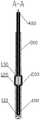
图2示出了图1沿A-A线的剖视图;Fig. 2 shows the sectional view of Fig. 1 along line A-A;
图3示出了图1的爆炸图;Figure 3 shows an exploded view of Figure 1;
图4示出了锚钉的使用状态图;Fig. 4 has shown the usage state figure of anchor;
图5示出了图4沿B-B线的剖视图;Fig. 5 shows the sectional view of Fig. 4 along line B-B;
图6示出了滑轮和滑槽的结构示意图。Figure 6 shows a schematic structural view of the pulley and the chute.
主要元件符号说明:Description of main component symbols:
100-缝线套管,110-第一过线孔,120-第二过线孔,130-第三过线孔,200-牵拉线,300-外管,400-插入器,410-肩状沉台,500-手柄,510-通孔,520-滑轮,530-滑槽。100-suture sleeve, 110-the first wire hole, 120-the second wire hole, 130-the third wire hole, 200-pull wire, 300-outer tube, 400-inserter, 410-shoulder Shape Shen platform, 500-handle, 510-through hole, 520-pulley, 530-chute.
具体实施方式detailed description
下面详细描述本发明的实施例,所述实施例的示例在附图中示出,其中自始至终相同或类似的标号表示相同或类似的元件或具有相同或类似功能的元件。下面通过参考附图描述的实施例是示例性的,仅用于解释本发明,而不能理解为对本发明的限制。Embodiments of the present invention are described in detail below, examples of which are shown in the drawings, wherein the same or similar reference numerals designate the same or similar elements or elements having the same or similar functions throughout. The embodiments described below by referring to the figures are exemplary only for explaining the present invention and should not be construed as limiting the present invention.
在本发明的描述中,需要理解的是,术语“中心”、“纵向”、“横向”、“长度”、“宽度”、“厚度”、“上”、“下”、“前”、“后”、“左”、“右”、“竖直”、“水平”、“顶”、“底”、“内”、“外”、“顺时针”、“逆时针”、“轴向”、“径向”、“周向”等指示的方位或位置关系为基于附图所示的方位或位置关系,仅是为了便于描述本发明和简化描述,而不是指示或暗示所指的装置或元件必须具有特定的方位、以特定的方位构造和操作,因此不能理解为对本发明的限制。In describing the present invention, it should be understood that the terms "center", "longitudinal", "transverse", "length", "width", "thickness", "upper", "lower", "front", " Back", "Left", "Right", "Vertical", "Horizontal", "Top", "Bottom", "Inner", "Outer", "Clockwise", "Counterclockwise", "Axial" , "radial", "circumferential" and other indicated orientations or positional relationships are based on the orientations or positional relationships shown in the drawings, which are only for the convenience of describing the present invention and simplifying the description, rather than indicating or implying the referred device or Elements must have certain orientations, be constructed and operate in certain orientations, and therefore should not be construed as limitations on the invention.
此外,术语“第一”、“第二”仅用于描述目的,而不能理解为指示或暗示相对重要性或者隐含指明所指示的技术特征的数量。由此,限定有“第一”、“第二”的特征可以明示或者隐含地包括一个或者更多个该特征。在本发明的描述中,“多个”的含义是两个或两个以上,除非另有明确具体的限定。In addition, the terms "first" and "second" are used for descriptive purposes only, and cannot be interpreted as indicating or implying relative importance or implicitly specifying the quantity of indicated technical features. Thus, a feature defined as "first" and "second" may explicitly or implicitly include one or more of these features. In the description of the present invention, "plurality" means two or more, unless otherwise specifically defined.
在本发明中,除非另有明确的规定和限定,术语“安装”、“相连”、“连接”、“固定”等术语应做广义理解,例如,可以是固定连接,也可以是可拆卸连接,或成一体;可以是机械连接,也可以是电连接;可以是直接相连,也可以通过中间媒介间接相连,可以是两个元件内部的连通或两个元件的相互作用关系。对于本领域的普通技术人员而言,可以根据具体情况理解上述术语在本发明中的具体含义。In the present invention, unless otherwise clearly specified and limited, terms such as "installation", "connection", "connection" and "fixation" should be understood in a broad sense, for example, it can be a fixed connection or a detachable connection , or integrated; it can be mechanically connected or electrically connected; it can be directly connected or indirectly connected through an intermediary, and it can be the internal communication of two components or the interaction relationship between two components. Those of ordinary skill in the art can understand the specific meanings of the above terms in the present invention according to specific situations.
在本发明中,除非另有明确的规定和限定,第一特征在第二特征“上”或“下”可以是第一和第二特征直接接触,或第一和第二特征通过中间媒介间接接触。而且,第一特征在第二特征“之上”、“上方”和“上面”可是第一特征在第二特征正上方或斜上方,或仅仅表示第一特征水平高度高于第二特征。第一特征在第二特征“之下”、“下方”和“下面”可以是第一特征在第二特征正下方或斜下方,或仅仅表示第一特征水平高度小于第二特征。In the present invention, unless otherwise clearly specified and limited, the first feature may be in direct contact with the first feature or the first and second feature may be in direct contact with the second feature through an intermediary. touch. Moreover, "above", "above" and "above" the first feature on the second feature may mean that the first feature is directly above or obliquely above the second feature, or simply means that the first feature is higher in level than the second feature. "Below", "beneath" and "beneath" the first feature may mean that the first feature is directly below or obliquely below the second feature, or simply means that the first feature is less horizontally than the second feature.
实施例一Embodiment one
请参阅图1,本发明提供一种全缝线锚钉,包括缝线套管100、牵拉线200、外管300和插入器400。所述外管300内设置所述缝线套管100,所述缝线套管100内穿设所述牵拉线200,所述牵拉线200包裹在所述插入器400上,所述缝线套管100和所述外管300与所述插入器400插接配合,所述牵拉线200的端部穿过所述缝线套管100内部位于所述外管300外端,所述插入器400用于将所述缝线套管100从所述外管300中推出,所述牵拉线200用于拉动所述缝线套管100回缩堆叠膨胀。Referring to FIG. 1 , the present invention provides a complete suture anchor, including a
在本实施例中,缝线套管100在使用前停留在外管300内部,缝线套管100与外管300和插入器400的连接方式为过盈配合,缝线套管100包裹在插入器400上,而外管300将缝线套管100紧紧地压缩在其内表面,缝线套管100在插入器400的作用下挤压变形储存能量。当缝线套管100开始使用时,推动插入器400向外管300内移动,插入器400端部将缝线套管100从外管300中顶出,缝线套管100不再受到外管300的限制释放能量并开始变形膨胀。In this embodiment, the
请参阅图2,当缝线套管100被完全顶出外管300时,缝线套管100变形结束,缝线套管100的直径与外管300的直径大致相同。此时,缝线套管100、插入器400和外管300三者之间的连接关系发生变化,缝线套管100紧密包裹在插入器400头端,二者属于紧密配合,插入器400上有一个肩状沉台410,与缝线套管100尾部相接触,限制了缝线套管100的向后运动。Referring to FIG. 2 , when the
在本实施例中,缝线套管100和牵拉线200组装在一起,二者由超高分子量聚乙烯纤维依靠线带编织机编织而成,缝线套管100是具有一定厚度的中空编织袋,因此缝线套管100在锚钉植入前能够与外管300内壁过盈配合,且中空结构的缝线套管100才能更好的从头端回缩。缝线套管100的作用是通过变形膨胀与骨组织侧面紧密贴合,从而为锚钉的固定提供支点。牵拉线200的作用是迫使缝线套管100变形膨胀,同时缝线远端可以连接软组织。In this embodiment, the
在本实施例中,外管300和插入器400是负责植入和辅助成结的功能性结构,都由SUS304医用不锈钢锻制而成,经过激光或线切割加工成指定尺寸和形状。In this embodiment, the
在本实施例中,牵拉线200与缝线套管100组成了一个完整的全缝线锚钉,但其成结需要插入器400和外管300的辅助,插入器400夹在缝线套管100内部,插入器400的作用是在植入锚钉时,为柔性缝线套管100提供刚性支撑,避免由于缝线套管100柔软的材质提前变形或无法脱离植入结构。而外管300则在缝线套管100进入骨道后限制缝线套管100尾端的移动,确保缝线套管100完全在骨道内部膨胀。In this embodiment, the
在本实施例中,插入器400为一种板状插入器,外管300和插入器400的配合是一种新型的植钉器,与传统双管植钉器在原理和结构运动过程上存在区别。传统的植钉器存在金属内管和金属外管,金属外管套金属内管,金属内管含锚钉,金属内管与金属外管之间滑动摩擦,使用时,先拉动金属内管使其向后移动,待锚钉完全露出后,金属内管停止移动,然后拉动牵拉线200,锚钉尾部受金属内管和金属外管的限位,锚钉将机械能转化为形变能,锚钉膨胀变形完成后植入动作完成,相比传统的植钉器,本装置能够通过更加简单的结构达到目的。In this embodiment, the
请参阅图3至图5,所述缝线套管100的头端向所述缝线套管100内回缩,所述缝线套管100回缩的头端侧面开设第一过线孔110,所述第一过线孔110中穿入所述牵拉线200,形成“膨胀引信”结构。所述缝线套管100尾端侧面对称开设两个第二过线孔120,位于所述缝线套管100内的所述牵拉线200两端分别从所述第二过线孔120中穿出所述缝线套管100,形成一组对称“锁止环”,所述缝线套管100侧面开设两个第三过线孔130,所述第三过线孔130位于所述第二过线孔120靠近所述外管300的一侧。所述牵拉线200的两端分别从同侧的所述第三过线孔130穿入所述缝线套管100内,最终从所述缝线套管100端部穿出,即为锁止结构。所述第二过线孔120与所述第三过线孔130之间的所述牵拉线200位于所述缝线套管100外。Please refer to Fig. 3 to Fig. 5, the head end of the
在本实施例中,进行锚钉植入动作时,牵拉线200和插入器400同时向后移动,由此产生一个向后的拉力,在此拉力的作用下,由于牵拉线200穿设在缝线套管100的回缩头端的侧面,因此缝线套管100的头端受拉向其尾端移动,缝线套管100头端从单层结构堆叠为双层结构。在缝线套管100变形过程中,外管300始终保持相对固定,外管300靠近缝线套管100的端部能够限制缝线套管100的持续移动,使得通过牵拉线200作用在缝线套管100上的力转换为缝线套管100的形变量。In this embodiment, when the anchor is implanted, the
当缝线套管100开始膨胀时,由于此时缝线套管100的堆叠作用,缝线套管100头端泊松比最大,第二过线孔120和第三过线孔130之间的缝线套管100侧面只受移动和限位的挤压作用,故此处的变形仅为压缩变形而变形不明显。缝线套管100膨胀完成后,缝线套管100的位移止于外管300靠近缝线套管100的端部,由于第二过线孔120和第三过线孔130处的缝线套管100变形而形成环状限位结构,缝线套管100尾部形成喇叭状结构,在摩擦阻力的作用下,缝线套管100的环状限位结构限制了缝线套管100头端正反方向的移动,即此时缝线套管100在骨组织内无法沿其长度方向移动,完成锁止动作。When the
请继续参阅图4和图5,所述缝线套管100头端上的所述牵拉线200端头将锚钉头部的一部分材料拉入所述缝线套管100,形成近似球状的内芯,此时所述缝线套管100形成内芯和外壳的双层结构,所述缝线套管100的环状限位结构将所述缝线套管100的内芯和外壳限制形成口袋状。此时,所述第二过线孔120和所述第三过线孔130之间的所述缝线套管100由于所述牵拉线200的拉力变形成类似于口袋绳扣结构。Please continue to refer to Fig. 4 and Fig. 5, the end of the pulling
在本实施例中,当本装置工作时,先在骨组织表面钻孔后准备插入锚钉,将锚钉插入至合适的深度,再通过插入器400将缝线套管100从外管300内推出,然后向外抽动牵拉线200和插入器400,此时缝线套管100头端向内回缩而膨胀呈圆球状,缝线套管100的直径大大增加,膨胀后的缝线套管100挤压周边骨组织,再抽出外管300,使外管300与缝线套管100分离,外管300和插入器400得到回收,使得缝线套管100固定在骨道内。缝线套管100在承担轴向拔出载荷时骨皮质层会产生与拉力方向相反的支反力,同时松质骨也会加压缝线套管100产生接触压力,使得缝线套管100稳固地停留在原位置。In this embodiment, when the device is working, the anchor is prepared to be inserted after drilling the surface of the bone tissue, the anchor is inserted to a suitable depth, and then the
实施例二Embodiment two
请参阅图1至图6,本实施例提供的全缝线锚钉是在上述实施例一的基础上对一些结构所做出的改进,相较于上述实施例一提供的全缝线锚钉,本实施例的具体改进如下:Please refer to Figures 1 to 6, the full suture anchor provided in this embodiment is an improvement on some structures based on the first embodiment above, compared with the full suture anchor provided in the first embodiment above , the specific improvements of this embodiment are as follows:
在本实施例提供的全缝线锚钉中,所述外管300和所述插入器400的远端均连接同一个手柄500,所述手柄500内部贯穿通孔510,所述外管300外表面与所述通孔510侧面固定连接,所述插入器400通过所述通孔510贯穿所述手柄500,所述插入器400位于所述手柄500内的侧面安装滑轮520,所述手柄500内开设滑槽530,所述滑轮520在所述手柄500内仅能沿所述滑槽530移动。In the full suture anchor provided in this embodiment, the
在本实施例中,外管300和插入器400的位移动作和连接关系均依靠手柄500来实现。当需要对缝线套管100进行打结操作时,通过手握手柄500限制手柄500的移动,由于外管300与手柄500固定连接,因此手柄500和外管300能保持相对静止。由于插入器400的运动被滑轮520和滑槽530限制,因此插入器400仅能沿滑槽530的长度方向做直线往复运动,能够避免插入器400与外管300发生相对转动而影响缝线套管100的成结,相反的,缝线套管100可以依靠插入器400与外管300两者间的相对运动完成成结过程。In this embodiment, the displacement action and connection relationship between the
实施例三Embodiment three
请参阅图1至图6,本实施例还提供一种植入设备,包括上述实施例一和实施例二所述的全缝线锚钉。Referring to FIG. 1 to FIG. 6 , this embodiment also provides an implantation device, including the full suture anchor described in the first and second embodiments above.
在本说明书的描述中,参考术语“一个实施例”、“一些实施例”、“示例”、“具体示例”、或“一些示例”等的描述意指结合该实施例或示例描述的具体特征、结构、材料或者特点包含于本发明的至少一个实施例或示例中。在本说明书中,对上述术语的示意性表述不必须针对的是相同的实施例或示例。而且,描述的具体特征、结构、材料或者特点可以在任一个或多个实施例或示例中以合适的方式结合。此外,在不相互矛盾的情况下,本领域的技术人员可以将本说明书中描述的不同实施例或示例以及不同实施例或示例的特征进行结合和组合。In the description of this specification, descriptions referring to the terms "one embodiment", "some embodiments", "example", "specific examples", or "some examples" mean that specific features described in connection with the embodiment or example , structure, material or characteristic is included in at least one embodiment or example of the present invention. In this specification, the schematic representations of the above terms are not necessarily directed to the same embodiment or example. Furthermore, the described specific features, structures, materials or characteristics may be combined in any suitable manner in any one or more embodiments or examples. In addition, those skilled in the art can combine and combine different embodiments or examples and features of different embodiments or examples described in this specification without conflicting with each other.
尽管上面已经示出和描述了本发明的实施例,可以理解的是,上述实施例是示例性的,不能理解为对本发明的限制,本领域的普通技术人员在本发明的范围内可以对上述实施例进行变化、修改、替换和变型。Although the embodiments of the present invention have been shown and described above, it can be understood that the above embodiments are exemplary and should not be construed as limiting the present invention, those skilled in the art can make the above-mentioned The embodiments are subject to changes, modifications, substitutions and variations.
Claims (8)
Translated fromChinesePriority Applications (4)
| Application Number | Priority Date | Filing Date | Title |
|---|---|---|---|
| CN202210034576.4ACN114366204B (en) | 2022-01-13 | 2022-01-13 | Full suture anchor and implantation equipment |
| PCT/CN2023/070846WO2023134556A1 (en) | 2022-01-13 | 2023-01-06 | Full suture anchor and implantation device |
| US18/030,082US20250082321A1 (en) | 2022-01-13 | 2023-01-06 | All-Suture Anchor and Implantable Device |
| EP23709304.2AEP4238508A4 (en) | 2022-01-13 | 2023-01-06 | FULL SUTURE ANCHOR AND IMPLANTATION DEVICE |
Applications Claiming Priority (1)
| Application Number | Priority Date | Filing Date | Title |
|---|---|---|---|
| CN202210034576.4ACN114366204B (en) | 2022-01-13 | 2022-01-13 | Full suture anchor and implantation equipment |
Publications (2)
| Publication Number | Publication Date |
|---|---|
| CN114366204A CN114366204A (en) | 2022-04-19 |
| CN114366204Btrue CN114366204B (en) | 2022-12-30 |
Family
ID=81144142
Family Applications (1)
| Application Number | Title | Priority Date | Filing Date |
|---|---|---|---|
| CN202210034576.4AActiveCN114366204B (en) | 2022-01-13 | 2022-01-13 | Full suture anchor and implantation equipment |
Country Status (4)
| Country | Link |
|---|---|
| US (1) | US20250082321A1 (en) |
| EP (1) | EP4238508A4 (en) |
| CN (1) | CN114366204B (en) |
| WO (1) | WO2023134556A1 (en) |
Families Citing this family (6)
| Publication number | Priority date | Publication date | Assignee | Title |
|---|---|---|---|---|
| CN114366204B (en)* | 2022-01-13 | 2022-12-30 | 北京天星博迈迪医疗器械有限公司 | Full suture anchor and implantation equipment |
| CN114831680A (en)* | 2022-06-02 | 2022-08-02 | 北京天星博迈迪医疗器械有限公司 | Full suture anchor implantation device |
| CN116712121B (en)* | 2023-08-07 | 2023-11-21 | 杭州翡宠生物科学有限公司 | Implant device |
| CN118902517B (en)* | 2024-08-23 | 2025-08-08 | 江苏唯德康医疗科技有限公司 | A tissue suturing system and an operating method thereof |
| CN118873196B (en)* | 2024-10-08 | 2025-02-07 | 北京天星医疗股份有限公司 | Manufacturing method of full-suture outer-row anchor and full-suture outer-row anchor |
| CN120078466B (en)* | 2025-04-25 | 2025-08-19 | 北京天星医疗股份有限公司 | Implant device and implant system for externally-arranged anchor |
Family Cites Families (28)
| Publication number | Priority date | Publication date | Assignee | Title |
|---|---|---|---|---|
| US5403348A (en)* | 1993-05-14 | 1995-04-04 | Bonutti; Peter M. | Suture anchor |
| FR2774580B1 (en)* | 1998-02-06 | 2000-09-08 | Laurent Fumex | BONE ANCHORING SURGICAL DEVICE |
| US7758594B2 (en)* | 2005-05-20 | 2010-07-20 | Neotract, Inc. | Devices, systems and methods for treating benign prostatic hyperplasia and other conditions |
| US8562647B2 (en)* | 2006-09-29 | 2013-10-22 | Biomet Sports Medicine, Llc | Method and apparatus for securing soft tissue to bone |
| CA2657619A1 (en)* | 2006-07-20 | 2008-01-24 | Lee D. Kaplan | Surgical instruments |
| US8814903B2 (en)* | 2009-07-24 | 2014-08-26 | Depuy Mitek, Llc | Methods and devices for repairing meniscal tissue |
| FR2965168A1 (en)* | 2010-09-23 | 2012-03-30 | Tornier Inc | SUTURE IMPLANT COMPONENT AND SUTURE IMPLANT DEVICE COMPRISING SUCH COMPONENT |
| US8795334B2 (en)* | 2011-01-28 | 2014-08-05 | Smith & Nephew, Inc. | Tissue repair |
| EP2675363B1 (en)* | 2011-02-16 | 2018-05-23 | Linvatec Corporation | Apparatus for securing an object to bone |
| CN116746973A (en)* | 2011-11-14 | 2023-09-15 | 亚瑟罗凯尔公司 | Tissue repair assembly |
| US9445803B2 (en)* | 2011-11-23 | 2016-09-20 | Howmedica Osteonics Corp. | Filamentary suture anchor |
| US9320512B2 (en)* | 2012-08-17 | 2016-04-26 | Arthrex, Inc. | Self-cinching soft anchors |
| CN103565485B (en)* | 2013-10-23 | 2015-07-15 | 孙思予 | Suture puncturing device, suture folding device, tissue perforation anastomat and anastomosis method thereof |
| US9962150B2 (en)* | 2013-12-20 | 2018-05-08 | Arthrocare Corporation | Knotless all suture tissue repair |
| US9949733B1 (en)* | 2014-01-03 | 2018-04-24 | Cayenne Medical, Inc. | All-suture suture anchor systems and methods |
| EP3297558B1 (en)* | 2015-05-22 | 2023-11-22 | Cayenne Medical, Inc. | Systems for repairing soft tissues |
| CN107296635B (en)* | 2016-06-29 | 2019-07-12 | 杭州锐健马斯汀医疗器材有限公司 | It is a kind of at knot medical suture and its at knot method |
| WO2018085663A1 (en)* | 2016-11-03 | 2018-05-11 | Smith & Nephew, Inc. | Tissue repair assembly and system with soft anchoring implant |
| US10631847B2 (en)* | 2017-05-24 | 2020-04-28 | Karl Storz Se & Co. Kg | Bone anchor including only suture material and delivery device thereof |
| CN107007314B (en)* | 2017-05-26 | 2023-09-01 | 上海利格泰生物科技股份有限公司 | Two-way self-locking full-suture anchor fixing device |
| EP4501247A3 (en)* | 2019-06-14 | 2025-04-23 | Smith & Nephew, Inc. | Soft anchoring tissue repair assembly and system |
| CN110215247A (en)* | 2019-06-25 | 2019-09-10 | 上海利格泰生物科技有限公司 | The more suture holdfasts of circle sheath and implanted device |
| US20230200799A1 (en)* | 2020-05-27 | 2023-06-29 | Smith & Nephew, Inc. | Tissue repair system |
| CN112515722B (en)* | 2020-12-01 | 2024-05-24 | 花沐医疗科技(上海)有限公司 | Full suture anchor structure and implantation device thereof |
| CN214259395U (en)* | 2020-12-23 | 2021-09-24 | 上海中医药大学附属曙光医院 | Bone-implantable full suture bag anchor implantation instrument |
| CN112754559B (en)* | 2021-01-27 | 2024-05-03 | 北京天星医疗股份有限公司 | Full-suture anchor and anchor traction forming set |
| CN215458300U (en)* | 2021-07-31 | 2022-01-11 | 江苏爱厚朴医疗器械有限公司 | Self-locking structure full suture anchor |
| CN114366204B (en)* | 2022-01-13 | 2022-12-30 | 北京天星博迈迪医疗器械有限公司 | Full suture anchor and implantation equipment |
- 2022
- 2022-01-13CNCN202210034576.4Apatent/CN114366204B/enactiveActive
- 2023
- 2023-01-06EPEP23709304.2Apatent/EP4238508A4/enactivePending
- 2023-01-06WOPCT/CN2023/070846patent/WO2023134556A1/ennot_activeCeased
- 2023-01-06USUS18/030,082patent/US20250082321A1/enactivePending
Also Published As
| Publication number | Publication date |
|---|---|
| US20250082321A1 (en) | 2025-03-13 |
| WO2023134556A1 (en) | 2023-07-20 |
| EP4238508A1 (en) | 2023-09-06 |
| CN114366204A (en) | 2022-04-19 |
| EP4238508A4 (en) | 2024-09-25 |
Similar Documents
| Publication | Publication Date | Title |
|---|---|---|
| CN114366204B (en) | Full suture anchor and implantation equipment | |
| EP1265534B1 (en) | A splint assembly for improving cardiac function in hearts | |
| CN112754559B (en) | Full-suture anchor and anchor traction forming set | |
| US20240366257A1 (en) | Stoma instrument and stoma method | |
| US20140018852A1 (en) | Anchor for securing a suture | |
| US20070055206A1 (en) | Methods and devices for deployment of tissue anchors | |
| EP2520229A3 (en) | In-vivo method and device for improving diastolic function of the left ventricle | |
| CN217014124U (en) | Full suture line anchor nail implanter | |
| KR20180098682A (en) | Clip cartridge | |
| CN212490016U (en) | Forward-pushing releasing type suture locking device | |
| CN113365563B (en) | Mechanical suture fastener | |
| CN113243972A (en) | Clamping device for minimally invasive surgery | |
| CN216257313U (en) | Ostomy appliance | |
| WO2022241755A1 (en) | Ring contraction apparatus for mitral valve annulus | |
| CN209360787U (en) | A kind of bracing wire auxiliary device for circular staplers | |
| CN117281565A (en) | Expansion type bone anchor with wire | |
| US20230025774A1 (en) | Forward-pushing for releasing suture locking device | |
| CN214857834U (en) | Annulus retractor for mitral valve annulus | |
| CN212661884U (en) | Puncture positioning needle device | |
| CN211381989U (en) | Valve ring retractor | |
| CN208456990U (en) | A kind of absorbable pulling rivet | |
| CN119770826B (en) | Stomach tube with convenient determination of implantation length | |
| CN219397757U (en) | Guiding device and pre-assembled conveying system | |
| CN114681140A (en) | A connecting mechanism and valve repair system | |
| CN217040239U (en) | Atrium ostomy device |
Legal Events
| Date | Code | Title | Description |
|---|---|---|---|
| PB01 | Publication | ||
| PB01 | Publication | ||
| SE01 | Entry into force of request for substantive examination | ||
| SE01 | Entry into force of request for substantive examination | ||
| GR01 | Patent grant | ||
| GR01 | Patent grant | ||
| CP01 | Change in the name or title of a patent holder | Address after:100176 A018, floor 1, building 1, No. 25, Jinghai Second Road, Beijing Economic and Technological Development Zone, Beijing Patentee after:Beijing Tianxing Medical Co.,Ltd. Address before:100176 A018, floor 1, building 1, No. 25, Jinghai Second Road, Beijing Economic and Technological Development Zone, Beijing Patentee before:BEIJING TIANXING BOMAIDI MEDICAL EQUIPMENT Co.,Ltd. | |
| CP01 | Change in the name or title of a patent holder |