CN114365021A - Spatially multiplexed volume Bragg gratings with variable thickness for waveguide displays - Google Patents
Spatially multiplexed volume Bragg gratings with variable thickness for waveguide displaysDownload PDFInfo
- Publication number
- CN114365021A CN114365021ACN202080059776.4ACN202080059776ACN114365021ACN 114365021 ACN114365021 ACN 114365021ACN 202080059776 ACN202080059776 ACN 202080059776ACN 114365021 ACN114365021 ACN 114365021A
- Authority
- CN
- China
- Prior art keywords
- grating
- light
- display
- waveguide
- vbg
- Prior art date
- Legal status (The legal status is an assumption and is not a legal conclusion. Google has not performed a legal analysis and makes no representation as to the accuracy of the status listed.)
- Pending
Links
- 239000000758substrateSubstances0.000claimsdescription155
- 239000000463materialSubstances0.000claimsdescription96
- 229920000642polymerPolymers0.000claimsdescription55
- 230000008878couplingEffects0.000claimsdescription15
- 238000010168coupling processMethods0.000claimsdescription15
- 238000005859coupling reactionMethods0.000claimsdescription15
- 230000000295complement effectEffects0.000claimsdescription3
- 210000001747pupilAnatomy0.000description106
- 239000006185dispersionSubstances0.000description77
- 239000013598vectorSubstances0.000description77
- 230000003287optical effectEffects0.000description72
- 230000000875corresponding effectEffects0.000description53
- 239000003086colorantSubstances0.000description43
- 230000006870functionEffects0.000description30
- 238000000034methodMethods0.000description29
- 230000005540biological transmissionEffects0.000description27
- 238000003384imaging methodMethods0.000description23
- 230000033001locomotionEffects0.000description23
- 230000002829reductive effectEffects0.000description23
- 230000009471actionEffects0.000description20
- 230000003190augmentative effectEffects0.000description18
- 230000003595spectral effectEffects0.000description16
- 238000004891communicationMethods0.000description15
- 230000009467reductionEffects0.000description15
- 230000010287polarizationEffects0.000description14
- 230000001902propagating effectEffects0.000description12
- 238000010586diagramMethods0.000description10
- 239000000178monomerSubstances0.000description10
- 239000011521glassSubstances0.000description9
- 238000005259measurementMethods0.000description9
- 238000000576coating methodMethods0.000description8
- 230000000694effectsEffects0.000description8
- 230000008569processEffects0.000description8
- 238000001228spectrumMethods0.000description8
- 238000013461designMethods0.000description7
- 238000005516engineering processMethods0.000description7
- 210000001525retinaAnatomy0.000description7
- 239000011248coating agentSubstances0.000description6
- 230000004075alterationEffects0.000description5
- 230000008859changeEffects0.000description5
- 230000001427coherent effectEffects0.000description5
- 210000003128headAnatomy0.000description5
- 230000004044responseEffects0.000description5
- 230000000007visual effectEffects0.000description5
- 229920001621AMOLEDPolymers0.000description4
- VYPSYNLAJGMNEJ-UHFFFAOYSA-NSilicium dioxideChemical compoundO=[Si]=OVYPSYNLAJGMNEJ-UHFFFAOYSA-N0.000description4
- 238000003491arrayMethods0.000description4
- 238000004590computer programMethods0.000description4
- 239000004973liquid crystal related substanceSubstances0.000description4
- 239000011159matrix materialSubstances0.000description4
- 229920003229poly(methyl methacrylate)Polymers0.000description4
- 239000004926polymethyl methacrylateSubstances0.000description4
- 230000001133accelerationEffects0.000description3
- 239000011230binding agentSubstances0.000description3
- 239000000919ceramicSubstances0.000description3
- 230000007423decreaseEffects0.000description3
- 239000002086nanomaterialSubstances0.000description3
- 239000002070nanowireSubstances0.000description3
- 239000011295pitchSubstances0.000description3
- 239000004033plasticSubstances0.000description3
- 229920003023plasticPolymers0.000description3
- 238000006116polymerization reactionMethods0.000description3
- 239000010453quartzSubstances0.000description3
- 230000010076replicationEffects0.000description3
- 241000699670Mus sp.Species0.000description2
- 239000006117anti-reflective coatingSubstances0.000description2
- 239000003795chemical substances by applicationSubstances0.000description2
- 239000013078crystalSubstances0.000description2
- 238000012217deletionMethods0.000description2
- 230000037430deletionEffects0.000description2
- 230000001419dependent effectEffects0.000description2
- 238000009792diffusion processMethods0.000description2
- 239000000975dyeSubstances0.000description2
- 239000010408filmSubstances0.000description2
- 230000014509gene expressionEffects0.000description2
- 239000003999initiatorSubstances0.000description2
- 230000000670limiting effectEffects0.000description2
- 239000007788liquidSubstances0.000description2
- 238000007726management methodMethods0.000description2
- 238000012986modificationMethods0.000description2
- 230000004048modificationEffects0.000description2
- 239000002245particleSubstances0.000description2
- 230000008447perceptionEffects0.000description2
- 238000012545processingMethods0.000description2
- 230000001953sensory effectEffects0.000description2
- 238000000926separation methodMethods0.000description2
- 230000007480spreadingEffects0.000description2
- 238000012546transferMethods0.000description2
- 238000001429visible spectrumMethods0.000description2
- 241000226585Antennaria plantaginifoliaSpecies0.000description1
- 108010010803GelatinProteins0.000description1
- 238000010521absorption reactionMethods0.000description1
- NIXOWILDQLNWCW-UHFFFAOYSA-Nacrylic acid groupChemical groupC(C=C)(=O)ONIXOWILDQLNWCW-UHFFFAOYSA-N0.000description1
- 238000007792additionMethods0.000description1
- 230000003667anti-reflective effectEffects0.000description1
- 238000013459approachMethods0.000description1
- 230000000712assemblyEffects0.000description1
- 238000000429assemblyMethods0.000description1
- 201000009310astigmatismDiseases0.000description1
- 230000008901benefitEffects0.000description1
- 230000010267cellular communicationEffects0.000description1
- 239000002131composite materialSubstances0.000description1
- 230000006835compressionEffects0.000description1
- 238000007906compressionMethods0.000description1
- 230000001010compromised effectEffects0.000description1
- 238000007796conventional methodMethods0.000description1
- 238000012937correctionMethods0.000description1
- 230000002596correlated effectEffects0.000description1
- 238000013500data storageMethods0.000description1
- 230000006837decompressionEffects0.000description1
- 230000003247decreasing effectEffects0.000description1
- 238000001514detection methodMethods0.000description1
- 239000003989dielectric materialSubstances0.000description1
- 239000000839emulsionSubstances0.000description1
- 230000004418eye rotationEffects0.000description1
- 229920000159gelatinPolymers0.000description1
- 239000008273gelatinSubstances0.000description1
- 235000019322gelatineNutrition0.000description1
- 235000011852gelatine dessertsNutrition0.000description1
- 238000002329infrared spectrumMethods0.000description1
- 230000000977initiatory effectEffects0.000description1
- 230000003993interactionEffects0.000description1
- 230000002452interceptive effectEffects0.000description1
- 238000002955isolationMethods0.000description1
- 230000007774longtermEffects0.000description1
- 239000003550markerSubstances0.000description1
- 229910044991metal oxideInorganic materials0.000description1
- 150000004706metal oxidesChemical class0.000description1
- 239000003607modifierSubstances0.000description1
- 239000002105nanoparticleSubstances0.000description1
- 239000002061nanopillarSubstances0.000description1
- 230000036961partial effectEffects0.000description1
- 239000002243precursorSubstances0.000description1
- 230000010344pupil dilationEffects0.000description1
- 238000002310reflectometryMethods0.000description1
- 239000004065semiconductorSubstances0.000description1
- 229910052709silverInorganic materials0.000description1
- 239000004332silverSubstances0.000description1
- -1silver halideChemical class0.000description1
- 239000007787solidSubstances0.000description1
- 238000004611spectroscopical analysisMethods0.000description1
- 230000003068static effectEffects0.000description1
- 239000010409thin filmSubstances0.000description1
- 238000013519translationMethods0.000description1
- 230000004304visual acuityEffects0.000description1
Images


Classifications
- G—PHYSICS
- G02—OPTICS
- G02B—OPTICAL ELEMENTS, SYSTEMS OR APPARATUS
- G02B27/00—Optical systems or apparatus not provided for by any of the groups G02B1/00 - G02B26/00, G02B30/00
- G02B27/01—Head-up displays
- G02B27/017—Head mounted
- G02B27/0172—Head mounted characterised by optical features
- G—PHYSICS
- G02—OPTICS
- G02B—OPTICAL ELEMENTS, SYSTEMS OR APPARATUS
- G02B1/00—Optical elements characterised by the material of which they are made; Optical coatings for optical elements
- G02B1/10—Optical coatings produced by application to, or surface treatment of, optical elements
- G02B1/11—Anti-reflection coatings
- G—PHYSICS
- G02—OPTICS
- G02B—OPTICAL ELEMENTS, SYSTEMS OR APPARATUS
- G02B27/00—Optical systems or apparatus not provided for by any of the groups G02B1/00 - G02B26/00, G02B30/00
- G02B27/0081—Optical systems or apparatus not provided for by any of the groups G02B1/00 - G02B26/00, G02B30/00 with means for altering, e.g. enlarging, the entrance or exit pupil
- G—PHYSICS
- G02—OPTICS
- G02B—OPTICAL ELEMENTS, SYSTEMS OR APPARATUS
- G02B27/00—Optical systems or apparatus not provided for by any of the groups G02B1/00 - G02B26/00, G02B30/00
- G02B27/42—Diffraction optics, i.e. systems including a diffractive element being designed for providing a diffractive effect
- G02B27/4205—Diffraction optics, i.e. systems including a diffractive element being designed for providing a diffractive effect having a diffractive optical element [DOE] contributing to image formation, e.g. whereby modulation transfer function MTF or optical aberrations are relevant
- G—PHYSICS
- G02—OPTICS
- G02B—OPTICAL ELEMENTS, SYSTEMS OR APPARATUS
- G02B27/00—Optical systems or apparatus not provided for by any of the groups G02B1/00 - G02B26/00, G02B30/00
- G02B27/42—Diffraction optics, i.e. systems including a diffractive element being designed for providing a diffractive effect
- G02B27/4272—Diffraction optics, i.e. systems including a diffractive element being designed for providing a diffractive effect having plural diffractive elements positioned sequentially along the optical path
- G—PHYSICS
- G02—OPTICS
- G02B—OPTICAL ELEMENTS, SYSTEMS OR APPARATUS
- G02B27/00—Optical systems or apparatus not provided for by any of the groups G02B1/00 - G02B26/00, G02B30/00
- G02B27/42—Diffraction optics, i.e. systems including a diffractive element being designed for providing a diffractive effect
- G02B27/44—Grating systems; Zone plate systems
- G—PHYSICS
- G02—OPTICS
- G02B—OPTICAL ELEMENTS, SYSTEMS OR APPARATUS
- G02B6/00—Light guides; Structural details of arrangements comprising light guides and other optical elements, e.g. couplings
- G02B6/0001—Light guides; Structural details of arrangements comprising light guides and other optical elements, e.g. couplings specially adapted for lighting devices or systems
- G02B6/0011—Light guides; Structural details of arrangements comprising light guides and other optical elements, e.g. couplings specially adapted for lighting devices or systems the light guides being planar or of plate-like form
- G02B6/0013—Means for improving the coupling-in of light from the light source into the light guide
- G02B6/0015—Means for improving the coupling-in of light from the light source into the light guide provided on the surface of the light guide or in the bulk of it
- G02B6/0016—Grooves, prisms, gratings, scattering particles or rough surfaces
- G—PHYSICS
- G02—OPTICS
- G02B—OPTICAL ELEMENTS, SYSTEMS OR APPARATUS
- G02B6/00—Light guides; Structural details of arrangements comprising light guides and other optical elements, e.g. couplings
- G02B6/0001—Light guides; Structural details of arrangements comprising light guides and other optical elements, e.g. couplings specially adapted for lighting devices or systems
- G02B6/0011—Light guides; Structural details of arrangements comprising light guides and other optical elements, e.g. couplings specially adapted for lighting devices or systems the light guides being planar or of plate-like form
- G02B6/0013—Means for improving the coupling-in of light from the light source into the light guide
- G02B6/0023—Means for improving the coupling-in of light from the light source into the light guide provided by one optical element, or plurality thereof, placed between the light guide and the light source, or around the light source
- G02B6/0026—Wavelength selective element, sheet or layer, e.g. filter or grating
- G—PHYSICS
- G02—OPTICS
- G02B—OPTICAL ELEMENTS, SYSTEMS OR APPARATUS
- G02B6/00—Light guides; Structural details of arrangements comprising light guides and other optical elements, e.g. couplings
- G02B6/0001—Light guides; Structural details of arrangements comprising light guides and other optical elements, e.g. couplings specially adapted for lighting devices or systems
- G02B6/0011—Light guides; Structural details of arrangements comprising light guides and other optical elements, e.g. couplings specially adapted for lighting devices or systems the light guides being planar or of plate-like form
- G02B6/0033—Means for improving the coupling-out of light from the light guide
- G02B6/0035—Means for improving the coupling-out of light from the light guide provided on the surface of the light guide or in the bulk of it
- G02B6/0038—Linear indentations or grooves, e.g. arc-shaped grooves or meandering grooves, extending over the full length or width of the light guide
- G—PHYSICS
- G02—OPTICS
- G02B—OPTICAL ELEMENTS, SYSTEMS OR APPARATUS
- G02B6/00—Light guides; Structural details of arrangements comprising light guides and other optical elements, e.g. couplings
- G02B6/0001—Light guides; Structural details of arrangements comprising light guides and other optical elements, e.g. couplings specially adapted for lighting devices or systems
- G02B6/0011—Light guides; Structural details of arrangements comprising light guides and other optical elements, e.g. couplings specially adapted for lighting devices or systems the light guides being planar or of plate-like form
- G02B6/0033—Means for improving the coupling-out of light from the light guide
- G02B6/005—Means for improving the coupling-out of light from the light guide provided by one optical element, or plurality thereof, placed on the light output side of the light guide
- G—PHYSICS
- G02—OPTICS
- G02B—OPTICAL ELEMENTS, SYSTEMS OR APPARATUS
- G02B6/00—Light guides; Structural details of arrangements comprising light guides and other optical elements, e.g. couplings
- G02B6/10—Light guides; Structural details of arrangements comprising light guides and other optical elements, e.g. couplings of the optical waveguide type
- G02B6/12—Light guides; Structural details of arrangements comprising light guides and other optical elements, e.g. couplings of the optical waveguide type of the integrated circuit kind
- G02B6/122—Basic optical elements, e.g. light-guiding paths
- G02B6/124—Geodesic lenses or integrated gratings
- G—PHYSICS
- G02—OPTICS
- G02B—OPTICAL ELEMENTS, SYSTEMS OR APPARATUS
- G02B6/00—Light guides; Structural details of arrangements comprising light guides and other optical elements, e.g. couplings
- G02B6/24—Coupling light guides
- G02B6/26—Optical coupling means
- G02B6/34—Optical coupling means utilising prism or grating
- H—ELECTRICITY
- H04—ELECTRIC COMMUNICATION TECHNIQUE
- H04N—PICTORIAL COMMUNICATION, e.g. TELEVISION
- H04N9/00—Details of colour television systems
- H04N9/12—Picture reproducers
- H04N9/31—Projection devices for colour picture display, e.g. using electronic spatial light modulators [ESLM]
- H04N9/3141—Constructional details thereof
- H04N9/315—Modulator illumination systems
- H04N9/3152—Modulator illumination systems for shaping the light beam
- G—PHYSICS
- G02—OPTICS
- G02B—OPTICAL ELEMENTS, SYSTEMS OR APPARATUS
- G02B27/00—Optical systems or apparatus not provided for by any of the groups G02B1/00 - G02B26/00, G02B30/00
- G02B27/01—Head-up displays
- G02B27/0101—Head-up displays characterised by optical features
- G02B2027/0112—Head-up displays characterised by optical features comprising device for genereting colour display
- G02B2027/0116—Head-up displays characterised by optical features comprising device for genereting colour display comprising devices for correcting chromatic aberration
- G—PHYSICS
- G02—OPTICS
- G02B—OPTICAL ELEMENTS, SYSTEMS OR APPARATUS
- G02B27/00—Optical systems or apparatus not provided for by any of the groups G02B1/00 - G02B26/00, G02B30/00
- G02B27/01—Head-up displays
- G02B27/0101—Head-up displays characterised by optical features
- G02B2027/0118—Head-up displays characterised by optical features comprising devices for improving the contrast of the display / brillance control visibility
- G02B2027/012—Head-up displays characterised by optical features comprising devices for improving the contrast of the display / brillance control visibility comprising devices for attenuating parasitic image effects
- G—PHYSICS
- G02—OPTICS
- G02B—OPTICAL ELEMENTS, SYSTEMS OR APPARATUS
- G02B27/00—Optical systems or apparatus not provided for by any of the groups G02B1/00 - G02B26/00, G02B30/00
- G02B27/01—Head-up displays
- G02B27/0101—Head-up displays characterised by optical features
- G02B2027/0123—Head-up displays characterised by optical features comprising devices increasing the field of view
- G02B2027/0125—Field-of-view increase by wavefront division
- G—PHYSICS
- G02—OPTICS
- G02B—OPTICAL ELEMENTS, SYSTEMS OR APPARATUS
- G02B27/00—Optical systems or apparatus not provided for by any of the groups G02B1/00 - G02B26/00, G02B30/00
- G02B27/01—Head-up displays
- G02B27/0101—Head-up displays characterised by optical features
- G02B2027/0138—Head-up displays characterised by optical features comprising image capture systems, e.g. camera
- G—PHYSICS
- G02—OPTICS
- G02B—OPTICAL ELEMENTS, SYSTEMS OR APPARATUS
- G02B27/00—Optical systems or apparatus not provided for by any of the groups G02B1/00 - G02B26/00, G02B30/00
- G02B27/01—Head-up displays
- G02B27/0101—Head-up displays characterised by optical features
- G02B2027/014—Head-up displays characterised by optical features comprising information/image processing systems
- G—PHYSICS
- G02—OPTICS
- G02B—OPTICAL ELEMENTS, SYSTEMS OR APPARATUS
- G02B27/00—Optical systems or apparatus not provided for by any of the groups G02B1/00 - G02B26/00, G02B30/00
- G02B27/01—Head-up displays
- G02B27/017—Head mounted
- G02B27/0172—Head mounted characterised by optical features
- G02B2027/0174—Head mounted characterised by optical features holographic
- G—PHYSICS
- G02—OPTICS
- G02B—OPTICAL ELEMENTS, SYSTEMS OR APPARATUS
- G02B27/00—Optical systems or apparatus not provided for by any of the groups G02B1/00 - G02B26/00, G02B30/00
- G02B27/01—Head-up displays
- G02B27/017—Head mounted
- G02B2027/0178—Eyeglass type
- G—PHYSICS
- G02—OPTICS
- G02B—OPTICAL ELEMENTS, SYSTEMS OR APPARATUS
- G02B27/00—Optical systems or apparatus not provided for by any of the groups G02B1/00 - G02B26/00, G02B30/00
- G02B27/01—Head-up displays
- G02B27/0179—Display position adjusting means not related to the information to be displayed
- G02B2027/0187—Display position adjusting means not related to the information to be displayed slaved to motion of at least a part of the body of the user, e.g. head, eye
Landscapes
- Physics & Mathematics (AREA)
- General Physics & Mathematics (AREA)
- Optics & Photonics (AREA)
- Engineering & Computer Science (AREA)
- Multimedia (AREA)
- Signal Processing (AREA)
- Microelectronics & Electronic Packaging (AREA)
- Diffracting Gratings Or Hologram Optical Elements (AREA)
- Devices For Indicating Variable Information By Combining Individual Elements (AREA)
- Eyeglasses (AREA)
- Surface Treatment Of Optical Elements (AREA)
Abstract
Description
Translated fromChinese发明领域Field of Invention
本发明总体上涉及用于近眼显示器的基于体布拉格光栅的波导显示器。The present invention generally relates to volume Bragg grating based waveguide displays for near eye displays.
技术背景technical background
诸如头戴式显示器(HMD)或平视显示器(HUD)系统的人工现实系统通常包括近眼显示器(例如,头戴式装置(headset)或一副眼镜的形式),该近眼显示器被配置成经由例如用户眼睛前方大约10mm-20mm内的电子显示器或光学显示器向用户呈现内容。如在虚拟现实(VR)、增强现实(AR)或混合现实(MR)应用中,近眼显示器可以显示虚拟对象或者将现实对象的图像与虚拟对象组合。例如,在AR系统中,用户可以通过例如透过透明的显示眼镜或透镜(通常被称为光学透视(optical see-through))来观看虚拟对象的图像(例如,计算机生成的图像(CGI))和周围环境两者。Artificial reality systems such as head mounted display (HMD) or head up display (HUD) systems typically include a near-eye display (eg, in the form of a headset or a pair of glasses) that is configured to be displayed via, eg, a user An electronic or optical display within approximately 10mm-20mm in front of the eye presents content to the user. As in virtual reality (VR), augmented reality (AR) or mixed reality (MR) applications, near-eye displays can display virtual objects or combine images of real objects with virtual objects. For example, in an AR system, a user may view an image (eg, computer-generated image (CGI)) of a virtual object, eg, through transparent display glasses or lenses (often referred to as optical see-through). and the surrounding environment.
一个示例光学透视AR系统可以使用基于波导的光学显示器,其中投影图像的光可以耦合到波导(例如,透明衬底)中,在波导内传播,并且在不同位置处从波导耦合出去。在一些实现中,可以使用衍射光学元件(例如光栅)将投影图像的光耦合到波导中或从波导耦合出去。来自周围环境的光可以穿过波导的透视区域,并且也到达用户的眼睛。An example optical see-through AR system may use a waveguide-based optical display, where the light of the projected image may be coupled into a waveguide (eg, a transparent substrate), propagate within the waveguide, and couple out of the waveguide at various locations. In some implementations, diffractive optical elements (eg, gratings) can be used to couple the light of the projected image into or out of the waveguide. Light from the surrounding environment can pass through the see-through area of the waveguide and also reach the user's eyes.
发明概述SUMMARY OF THE INVENTION
本发明总体上涉及用于近眼显示器的基于体布拉格光栅的波导显示器。更具体地说,本文公开了使用体布拉格光栅(VBG)耦合器来扩展视窗(eyebox)、减少显示雾度(haze)、减小物理尺寸、提高光学效率、减少光学伪像和增加光学透视近眼显示系统的视场的技术。本文描述了各种发明实施例,包括设备、系统、方法等。The present invention generally relates to volume Bragg grating based waveguide displays for near eye displays. More specifically, disclosed herein is the use of volume Bragg grating (VBG) couplers to expand the eyebox, reduce display haze, reduce physical size, increase optical efficiency, reduce optical artifacts, and increase optical perspective near the eye Technology that displays the field of view of the system. Various inventive embodiments are described herein, including devices, systems, methods, and the like.
在一个方面,本发明提供了一种波导显示器,该波导显示器可以包括波导和光栅耦合器,该光栅耦合器被配置为将显示光耦合到波导中或从波导耦合出去。光栅耦合器可以至少包括排列成叠层(stack)的第一光栅层和第二光栅层。第一光栅层可以以第一厚度为特征,并且可以包括被配置为衍射来自第一视场的第一波长的显示光的第一透射式VBG(transmission VBG)。第二光栅层可以以大于第一厚度的第二厚度为特征,并且可以包括第二透射式VBG,该第二透射式VBG被配置为衍射来自比第一视场大的第二视场的第一波长的显示光。In one aspect, the present invention provides a waveguide display that may include a waveguide and a grating coupler configured to couple display light into or out of the waveguide. The grating coupler may include at least a first grating layer and a second grating layer arranged in a stack. The first grating layer may be characterized by a first thickness, and may include a first transmission VBG configured to diffract display light of the first wavelength from the first field of view. The second grating layer can be characterized by a second thickness that is greater than the first thickness, and can include a second transmissive VBG configured to diffract the first One wavelength of display light.
在波导显示器的一些实施例中,第一透射式VBG可以进一步被配置为衍射来自比第一视场小的第三视场的比第一波长更长的第二波长的显示光。第二透射式VBG可以进一步被配置为衍射来自比第二视场小的第四视场的第二波长的显示光。第一光栅层和第二光栅层可以各自包括全息材料层。第一光栅层可以包括第一多路复用VBG(multiplexedVBG),该第一多路复用VBG包括以第一多次全息记录曝光所记录的第一多个透射式VBG。第二光栅层可以包括第二多路复用VBG,该第二多路复用VBG包括以第二多次全息记录曝光所记录的第二多个透射式VBG。波导显示器可以进一步包括在第一光栅层和第二光栅层之间的衬底,其中衬底可以对可见光透明。In some embodiments of the waveguide display, the first transmissive VBG may be further configured to diffract display light at a second wavelength longer than the first wavelength from a third field of view that is smaller than the first field of view. The second transmissive VBG may be further configured to diffract display light of a second wavelength from a fourth field of view that is smaller than the second field of view. The first grating layer and the second grating layer may each include a holographic material layer. The first grating layer may include a first multiplexed VBG (multiplexed VBG) including a first plurality of transmissive VBGs recorded with a first plurality of holographic recording exposures. The second grating layer may include a second multiplexed VBG including a second plurality of transmissive VBGs recorded with a second plurality of holographic recording exposures. The waveguide display can further include a substrate between the first grating layer and the second grating layer, wherein the substrate can be transparent to visible light.
在波导显示器的一些实施例中,光栅耦合器可以进一步包括叠层中的第三光栅层,其中第三光栅层可以以大于第二厚度的第三厚度为特征,并且可以包括被配置为衍射来自比第二视场大的第三视场的第一波长的显示光的第三透射式VBG。在一些实施例中,第三厚度可以小于100μm。In some embodiments of the waveguide display, the grating coupler can further include a third grating layer in the stack, wherein the third grating layer can be characterized by a third thickness that is greater than the second thickness, and can include a third grating layer configured to diffract from A third transmissive VBG of the display light of the first wavelength of the third field of view, which is larger than the second field of view. In some embodiments, the third thickness may be less than 100 μm.
在一些实施例中,波导可以对可见光透明,并且光栅耦合器可以对来自周围环境的可见光透明。在一些实施例中,波导显示器可以包括第二光栅耦合器,该第二光栅耦合器被配置为将显示光耦合到波导中或从波导耦合出去,或者改变显示光在波导内的传播方向。In some embodiments, the waveguide may be transparent to visible light, and the grating coupler may be transparent to visible light from the surrounding environment. In some embodiments, the waveguide display can include a second grating coupler configured to couple display light into or out of the waveguide, or to change the direction of propagation of the display light within the waveguide.
在另一方面,本发明提供了一种波导显示器,其可以包括波导和光栅耦合器,该光栅耦合器被配置为将显示光耦合到波导中或从波导耦合出去。光栅耦合器可以包括光栅层,该光栅层以不均匀的厚度为特征,并且至少包括第一区域和第二区域。光栅层的第一区域可以以第一厚度为特征,并且可以包括第一透射式VBG,该第一透射式VBG被配置为衍射来自第一视场的第一波长的显示光。光栅层的第二区域可以以大于第一厚度的第二厚度为特征,并且可以包括被配置为衍射来自比第一视场大的第二视场的第一波长的显示光的第二透射式VBG。In another aspect, the present invention provides a waveguide display that can include a waveguide and a grating coupler configured to couple display light into or out of the waveguide. The grating coupler may include a grating layer characterized by a non-uniform thickness and including at least a first region and a second region. The first region of the grating layer may be characterized by a first thickness and may include a first transmissive VBG configured to diffract display light at a first wavelength from the first field of view. The second region of the grating layer can be characterized by a second thickness that is greater than the first thickness, and can include a second transmissive pattern configured to diffract display light of the first wavelength from a second field of view that is greater than the first field of view VBG.
在波导显示器的一些实施例中,第一透射式VBG可以进一步被配置成衍射来自比第一视场小的第三视场的比第一波长更长的第二波长的显示光。第二透射式VBG还可以被配置为衍射来自比第二视场小的第四视场的第二波长的显示光。在一些实施例中,第一区域可以包括第一多路复用VBG,该第一多路复用VBG包括以第一多次全息记录曝光所记录的第一多个透射式VBG,并且第二区域可以包括第二多路复用VBG,该第二多路复用VBG包括以第二多次全息记录曝光所记录的第二多个透射式VBG。In some embodiments of the waveguide display, the first transmissive VBG may be further configured to diffract display light at a second wavelength longer than the first wavelength from a third field of view that is smaller than the first field of view. The second transmissive VBG may also be configured to diffract display light of a second wavelength from a fourth field of view that is smaller than the second field of view. In some embodiments, the first region may include a first multiplexed VBG including the first plurality of transmissive VBGs recorded with the first plurality of holographic recording exposures, and the second multiplexed VBG The area may include a second multiplexed VBG including a second plurality of transmissive VBGs recorded with a second plurality of holographic recording exposures.
在一些实施例中,波导显示器可以进一步包括具有第二非均匀厚度的衬底,其中光栅层可以形成在衬底上,并且衬底可以在光栅层的第一区域处具有第三厚度,以及在光栅层的第二区域处具有第四厚度。第三厚度可以大于第四厚度。衬底和光栅层可以形成以均匀厚度为特征的组合层。In some embodiments, the waveguide display can further include a substrate having a second non-uniform thickness, wherein the grating layer can be formed on the substrate, and the substrate can have a third thickness at the first region of the grating layer, and The grating layer has a fourth thickness at the second region. The third thickness may be greater than the fourth thickness. The substrate and grating layers may form a combined layer characterized by a uniform thickness.
在一些实施例中,波导显示器可以进一步包括具有第二非均匀厚度的聚合物层,该第二非均匀厚度与光栅层的非均匀厚度互补,使得聚合物层和光栅层可以形成以均匀厚度为特征的组合层。具有第二非均匀厚度的聚合物层可以通过使用非均匀光图案选择性地减敏以均匀厚度为特征的全息材料层来形成。光栅层可以形成在全息材料层的光敏部分中。In some embodiments, the waveguide display can further include a polymer layer having a second non-uniform thickness that is complementary to the non-uniform thickness of the grating layer, such that the polymer layer and the grating layer can be formed with a uniform thickness of A composite layer of features. The polymer layer having a second non-uniform thickness can be formed by selectively desensitizing the layer of holographic material characterized by a uniform thickness using a non-uniform light pattern. The grating layer may be formed in the photosensitive portion of the holographic material layer.
在波导显示器的一些实施例中,光栅层的最大厚度可以小于100μm。在一些实施例中,波导可以对可见光透明,并且光栅耦合器可以对来自周围环境的可见光透明。在一些实施例中,波导显示器可以进一步包括第二光栅耦合器,该第二光栅耦合器被配置为将显示光耦合到波导中或从波导耦合出去,或者改变显示光在波导中的传播方向。In some embodiments of the waveguide display, the maximum thickness of the grating layer may be less than 100 μm. In some embodiments, the waveguide may be transparent to visible light, and the grating coupler may be transparent to visible light from the surrounding environment. In some embodiments, the waveguide display may further include a second grating coupler configured to couple display light into or out of the waveguide, or to change the direction of propagation of the display light in the waveguide.
在另一方面,本发明提供了一种波导显示器,其可以包括波导和光栅耦合器,该光栅耦合器被配置为将显示光耦合到波导中或从波导耦合出去。光栅耦合器可以包括排列成叠层并且以不同的相应厚度为特征的多个光栅层,以及与多个光栅层交错的多个衬底。多个衬底可以对可见光透明。多个光栅层可以至少包括第一光栅层和第二光栅层。第一光栅层可以以第一厚度为特征,并且可以包括第一多路复用透射式VBG,该第一多路复用透射式VBG包括被配置为衍射来自第一视场的第一波长的显示光的第一透射式VBG。第二光栅层可以以大于第一厚度的第二厚度为特征,并且可以包括第二多路复用透射式VBG,该第二多路复用透射式VBG包括被配置为衍射来自比第一视场大的第二视场的第一波长的可见光的第二透射式VBG。In another aspect, the present invention provides a waveguide display that can include a waveguide and a grating coupler configured to couple display light into or out of the waveguide. A grating coupler may include a plurality of grating layers arranged in a stack and characterized by different respective thicknesses, and a plurality of substrates interleaved with the plurality of grating layers. The plurality of substrates may be transparent to visible light. The plurality of grating layers may include at least a first grating layer and a second grating layer. The first grating layer can be characterized by a first thickness and can include a first multiplexed transmissive VBG including a A first transmissive VBG of light is displayed. The second grating layer can be characterized by a second thickness that is greater than the first thickness, and can include a second multiplexed transmissive VBG that includes a second multiplexed transmissive VBG that is configured to diffract images from a A second transmissive VBG of visible light of the first wavelength of the second field of view with a large field.
本概述既不意图标识所要求保护的主题的关键或必要特征,也不意图孤立地用于确定所要求保护的主题的范围。应当参照本公开内容的整个说明书的适当部分、任何或所有附图以及每项权利要求来理解主题。下面将在以下说明书、权利要求书和附图中更详细地描述前述内容以及其他特征和示例。应当理解,被讨论为适合包含在本文描述的任何方面中的任何特征也适合以任何组合包含在任何其他方面中。This Summary is neither intended to identify key or essential features of the claimed subject matter, nor is it intended to be used in isolation to determine the scope of the claimed subject matter. The subject matter should be understood by reference to the appropriate portions of the entire specification of the present disclosure, any or all drawings, and each claim. The foregoing, as well as other features and examples, will be described in more detail below in the following specification, claims, and drawings. It should be understood that any feature discussed as suitable for inclusion in any aspect described herein is also suitable for inclusion in any other aspect, in any combination.
附图简述Brief Description of Drawings
下面参照以下附图详细地描述说明性的实施例。Illustrative embodiments are described in detail below with reference to the following figures.
图1是根据某些实施例的包括近眼显示系统的人工现实系统环境的示例的简化框图。1 is a simplified block diagram of an example of an artificial reality system environment including a near-eye display system, according to some embodiments.
图2是用于实现本文公开的一些示例的头戴式显示器(HMD)设备形式的近眼显示系统的示例的透视图。2 is a perspective view of an example of a near-eye display system in the form of a head mounted display (HMD) device for implementing some example disclosed herein.
图3是用于实现本文公开的一些示例的一副眼镜形式的近眼显示系统的示例的透视图。3 is a perspective view of an example of a near-eye display system in the form of a pair of glasses for implementing some examples disclosed herein.
图4是示出近眼显示系统中的光学系统的示例的简化图。4 is a simplified diagram illustrating an example of an optical system in a near-eye display system.
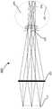
图5示出了根据某些实施例的包括用于出射光瞳扩展(exit pupil expansion)的波导显示器的光学透视增强现实系统的示例。5 illustrates an example of an optical see-through augmented reality system including a waveguide display for exit pupil expansion, according to some embodiments.
图6示出了根据某些实施例的包括用于出射光瞳扩展的波导显示器的光学透视增强现实系统的示例。6 illustrates an example of an optical see-through augmented reality system including a waveguide display for exit pupil expansion, according to some embodiments.
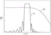
图7A示出了反射式体布拉格光栅(VBG)的示例的光谱带宽和透射式表面浮雕光栅(SRG)的示例的光谱带宽。图7B示出了反射式VBG(reflection VBG)的示例的角度带宽和透射式SRG(transmissive SRG)的示例的角度带宽。7A shows the spectral bandwidth of an example of a reflective volume Bragg grating (VBG) and an example of a transmissive surface relief grating (SRG). FIG. 7B shows an example angular bandwidth of a reflective VBG (reflection VBG) and an example angular bandwidth of a transmissive SRG (transmissive SRG).
图8A示出了根据某些实施例的光学透视增强现实系统的示例,该系统包括波导显示器和用于出射光瞳扩展的表面浮雕光栅。图8B示出了根据某些实施例的包括二维复制出射光瞳的视窗(eye box)的示例。8A illustrates an example of an optical see-through augmented reality system including a waveguide display and a surface relief grating for exit pupil expansion, according to some embodiments. 8B shows an example of an eye box including a two-dimensionally replicated exit pupil, according to some embodiments.
图9A示出了由表面浮雕光栅的示例衍射的光的波矢量,该表面浮雕光栅用于波导显示器中的出射光瞳扩展和多种颜色的出射光瞳。图9B通过波导显示器中用于出射光瞳扩展的表面浮雕光栅的示例示出了视场截断(clipping)。9A shows the wave vector of light diffracted by an example of a surface relief grating used for exit pupil expansion and multi-color exit pupils in waveguide displays. Figure 9B illustrates field clipping with an example of a surface relief grating for exit pupil expansion in a waveguide display.
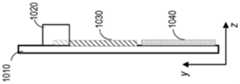
图10A示出了根据某些实施例的基于体布拉格光栅的波导显示器的示例。图10B示出了图10A所示的基于体布拉格光栅的波导显示器的示例的俯视图。图10C示出了图10A所示的基于体布拉格光栅的波导显示器的示例的侧视图。10A illustrates an example of a volume Bragg grating based waveguide display in accordance with certain embodiments. FIG. 10B shows a top view of the example of the volume Bragg grating based waveguide display shown in FIG. 10A . 10C shows a side view of the example of the volume Bragg grating based waveguide display shown in FIG. 10A.
图11示出了根据某些实施例的基于体布拉格光栅的波导显示器的示例中的光色散(light dispersion)。11 illustrates light dispersion in an example of a volume Bragg grating based waveguide display according to some embodiments.
图12A示出了体布拉格光栅(VBG)的示例。图12B示出了图12A所示的体布拉格光栅的布拉格条件。FIG. 12A shows an example of a volume Bragg grating (VBG). Fig. 12B shows the Bragg conditions of the volume Bragg grating shown in Fig. 12A.
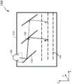
图13A示出了根据某些实施例的具有出射光瞳扩展和色散减小的基于体布拉格光栅的波导显示器的示例的前视图。图13B示出了图13A所示的基于体布拉格光栅的波导显示器的示例的侧视图。13A illustrates a front view of an example of a volume Bragg grating-based waveguide display with exit pupil expansion and dispersion reduction in accordance with certain embodiments. Figure 13B shows a side view of the example of the volume Bragg grating based waveguide display shown in Figure 13A.
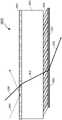
图14A示出了根据某些实施例的来自不同视场的光在基于反射式体布拉格光栅的波导显示器中的传播。图14B示出了根据某些实施例的来自不同视场的光在基于透射式体布拉格光栅的波导显示器中的传播。14A illustrates the propagation of light from different fields of view in a reflective volume Bragg grating based waveguide display in accordance with certain embodiments. 14B illustrates the propagation of light from different fields of view in a transmissive volume Bragg grating based waveguide display in accordance with certain embodiments.
图15示出了根据某些实施例的具有出射光瞳扩展和色散减小的基于反射式体布拉格光栅的波导显示器的示例。15 illustrates an example of a reflective volume Bragg grating based waveguide display with exit pupil expansion and dispersion reduction in accordance with certain embodiments.
图16示出了根据某些实施例的具有出射光瞳扩展和形状因子减小的基于透射式体布拉格光栅的波导显示器的示例。16 illustrates an example of a transmissive volume Bragg grating-based waveguide display with exit pupil expansion and form factor reduction in accordance with certain embodiments.
图17A示出了根据某些实施例的波导显示器中的透射式体布拉格光栅的示例。图17B示出了波导显示器中的透射式VBG的示例,其中被反射式VBG衍射的光没有在波导中被全反射和引导。图17C示出了根据某些实施例的波导显示器中的反射式体布拉格光栅的示例。图17D示出了波导显示器中的反射式VBG的示例,其中被透射式VBG衍射的光没有在波导中被全反射和引导。17A shows an example of a transmissive volume Bragg grating in a waveguide display according to some embodiments. Figure 17B shows an example of a transmissive VBG in a waveguide display, where the light diffracted by the reflective VBG is not totally reflected and guided in the waveguide. 17C shows an example of a reflective volume Bragg grating in a waveguide display according to some embodiments. Figure 17D shows an example of a reflective VBG in a waveguide display where the light diffracted by the transmissive VBG is not totally reflected and guided in the waveguide.
图18A示出了根据某些实施例的波导显示器中的反射式体布拉格光栅的示例的光色散。图18B示出了根据某些实施例的波导显示器中的透射式体布拉格光栅的示例的光色散。Figure 18A illustrates example light dispersion of a reflective volume Bragg grating in a waveguide display according to some embodiments. Figure 18B illustrates the optical dispersion of an example of a transmissive volume Bragg grating in a waveguide display according to some embodiments.
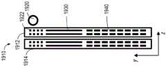
图19A是根据某些实施例的具有出射光瞳扩展和色散减小的基于体布拉格光栅的波导显示器的示例的正视图。图19B是根据某些实施例的包括图像投影仪和多个聚合物层的基于体布拉格光栅的波导显示器的示例的侧视图。19A is a front view of an example of a volume Bragg grating-based waveguide display with exit pupil expansion and dispersion reduction in accordance with certain embodiments. 19B is a side view of an example of a volume Bragg grating-based waveguide display including an image projector and multiple polymer layers, according to some embodiments.
图20A示出了根据某些实施例的具有出射光瞳扩展、色散减小、形状因子减小和功率效率提高的基于体布拉格光栅的波导显示器的另一个示例。图20B示出了在图20A中所示的基于体布拉格光栅的波导显示器的视窗处的复制出射光瞳的示例。20A illustrates another example of a volume Bragg grating-based waveguide display with exit pupil expansion, reduced dispersion, reduced form factor, and improved power efficiency in accordance with certain embodiments. Figure 20B shows an example of a replicated exit pupil at the viewing window of the volume Bragg grating based waveguide display shown in Figure 20A.
图21A示出了根据某些实施例的具有出射光瞳扩展、色散减小和形状因子减小的基于体布拉格光栅的波导显示器的示例。图21B示出了根据某些实施例的具有出射光瞳扩展、色散减小、形状因子减小和效率提高的基于体布拉格光栅的波导显示器的示例。21A shows an example of a volume Bragg grating based waveguide display with exit pupil expansion, dispersion reduction, and form factor reduction in accordance with certain embodiments. 21B shows an example of a volume Bragg grating-based waveguide display with exit pupil expansion, reduced dispersion, reduced form factor, and improved efficiency, in accordance with certain embodiments.
图22A是根据某些实施例的包括两个图像投影仪的基于体布拉格光栅的波导显示器的示例的正视图。图22B是根据某些实施例的包括两个图像投影仪的基于体布拉格光栅的波导显示器的示例的侧视图。22A is a front view of an example of a volume Bragg grating-based waveguide display including two image projectors, according to some embodiments. 22B is a side view of an example of a volume Bragg grating-based waveguide display including two image projectors, according to some embodiments.
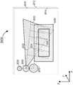
图23A是根据某些实施例的基于体布拉格光栅的波导显示器的示例的正视图,该波导显示器包括单个图像投影仪和用于视场拼接的光栅。图23B是根据某些实施例的基于体布拉格光栅的波导显示器的示例的侧视图,该波导显示器具有单个图像投影仪和用于视场拼接的光栅。23A is a front view of an example of a volume Bragg grating-based waveguide display including a single image projector and a grating for field-of-view stitching, in accordance with certain embodiments. 23B is a side view of an example of a volume Bragg grating-based waveguide display with a single image projector and grating for field-of-view stitching, in accordance with certain embodiments.
图24示出了根据某些实施例的基于体布拉格光栅的波导显示器的示例,该波导显示器包括用于不同视场和/或光波长的多个光栅层。24 illustrates an example of a volume Bragg grating-based waveguide display that includes multiple grating layers for different fields of view and/or wavelengths of light, according to some embodiments.
图25示出了根据某些实施例的基于体布拉格光栅的波导显示器的示例中的多个光栅的视场。25 illustrates fields of view of multiple gratings in an example of a volume Bragg grating-based waveguide display, according to some embodiments.
图26A示出了体布拉格光栅的示例对来自不同对应视场的不同颜色的光的衍射。图26B示出了体布拉格光栅的光栅周期和不同颜色入射光的相应视场之间的关系。Figure 26A shows the diffraction of light of different colors from different corresponding fields of view by an example of a volume Bragg grating. Figure 26B shows the relationship between the grating period of the volume Bragg grating and the corresponding fields of view for different colors of incident light.
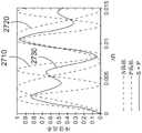
图27A示出了具有相同厚度但不同折射率调制的透射式体布拉格光栅的示例的衍射效率。图27B示出了具有相同厚度但不同折射率调制的反射式体布拉格光栅的示例的衍射效率。Figure 27A shows the diffraction efficiency of examples of transmissive volume Bragg gratings with the same thickness but different refractive index modulations. Figure 27B shows the diffraction efficiency of examples of reflective volume Bragg gratings with the same thickness but different refractive index modulations.
图28A示出了作为入射角从布拉格条件的偏离的函数的具有第一折射率调制的透射式体布拉格光栅的示例的衍射效率。图28B示出了作为入射角从布拉格条件的偏离的函数的具有第二折射率调制的透射式体布拉格光栅的示例的衍射效率。图28C示出了作为入射角从布拉格条件的偏离的函数的具有第三折射率调制的透射式体布拉格光栅的示例的衍射效率。图28D示出了作为入射角从布拉格条件的偏离的函数的具有第四折射率调制的透射式体布拉格光栅的示例的衍射效率。28A shows the diffraction efficiency of an example of a transmissive volume Bragg grating with a first refractive index modulation as a function of the deviation of the incident angle from the Bragg condition. 28B shows the diffraction efficiency of an example of a transmissive volume Bragg grating with a second index modulation as a function of the deviation of the incident angle from the Bragg condition. 28C shows the diffraction efficiency of an example of a transmissive volume Bragg grating with a third index modulation as a function of the deviation of the incident angle from the Bragg condition. Figure 28D shows the diffraction efficiency of an example of a transmissive volume Bragg grating with a fourth refractive index modulation as a function of the deviation of the incident angle from the Bragg condition.
图29A示出了作为入射角从布拉格条件的偏离的函数的具有第一折射率调制的反射式体布拉格光栅的示例的衍射效率。图29B示出了作为入射角从布拉格条件的偏离的函数的具有第二折射率调制的反射式体布拉格光栅的示例的衍射效率。图29C示出了作为入射角从布拉格条件的偏离的函数的具有第三折射率调制的反射式体布拉格光栅的示例的衍射效率。图29D示出了作为入射角从布拉格条件的偏离的函数的具有第四折射率调制的反射式体布拉格光栅的示例的衍射效率。29A shows the diffraction efficiency of an example of a reflective volume Bragg grating with a first refractive index modulation as a function of the deviation of the incident angle from the Bragg condition. 29B shows the diffraction efficiency of an example of a reflective volume Bragg grating with a second index modulation as a function of the deviation of the incident angle from the Bragg condition. 29C shows the diffraction efficiency of an example of a reflective volume Bragg grating with a third index modulation as a function of the deviation of the incident angle from the Bragg condition. 29D shows the diffraction efficiency of an example of a reflective volume Bragg grating with a fourth refractive index modulation as a function of the deviation of the incident angle from the Bragg condition.
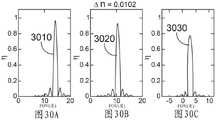
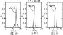
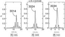
图30A示出了具有第一折射率调制的透射式VBG的示例对于来自不同视场的蓝光的衍射效率。图30B示出了具有第一折射率调制的透射式VBG的示例对于来自不同视场的绿光的衍射效率。图30C示出了具有第一折射率调制的透射式VBG的示例对于来自不同视场的红光的衍射效率。图30D示出了具有第二折射率调制的透射式VBG的示例对于来自不同视场的蓝光的衍射效率。图30E示出了具有第二折射率调制的透射式VBG的示例对于来自不同视场的绿光的衍射效率。图30F示出了具有第二折射率调制的透射式VBG的示例对于来自不同视场的红光的衍射效率。图30G示出了具有第三折射率调制的透射式VBG的示例对于来自不同视场的蓝光的衍射效率。图30H示出了具有第三折射率调制的透射式VBG的示例对于来自不同视场的绿光的衍射效率。图30I示出了具有第三折射率调制的透射式VBG的示例对于来自不同视场的红光的衍射效率。30A shows the diffraction efficiency of an example of a transmissive VBG with a first refractive index modulation for blue light from different fields of view. 30B shows the diffraction efficiency of an example of a transmissive VBG with a first refractive index modulation for green light from different fields of view. 30C shows the diffraction efficiency of an example of a transmissive VBG with a first refractive index modulation for red light from different fields of view. 30D shows the diffraction efficiency of an example of a transmissive VBG with a second refractive index modulation for blue light from different fields of view. 30E shows the diffraction efficiency of an example of a transmissive VBG with a second refractive index modulation for green light from different fields of view. 30F shows the diffraction efficiency of an example of a transmissive VBG with a second refractive index modulation for red light from different fields of view. 30G shows the diffraction efficiency of an example of a transmissive VBG with a third refractive index modulation for blue light from different fields of view. 30H shows the diffraction efficiency of an example of a transmissive VBG with a third index modulation for green light from different fields of view. 30I shows the diffraction efficiency of an example of a transmissive VBG with a third index modulation for red light from different fields of view.
图31A示出了为了实现不同颜色光的衍射饱和,具有不同光栅周期的透射式体布拉格光栅的最小折射率调制。图31B示出了为了避免蓝光、绿光和红光的折射率调制饱和,具有不同光栅周期的透射式光栅的最大折射率调制。图31C示出了根据某些实施例的光栅层的示例,该光栅层包括具有不同间距和折射率调制的多路复用VBG,用于优化衍射效率和均匀性。FIG. 31A shows the minimum refractive index modulation of transmissive volume Bragg gratings with different grating periods in order to achieve diffraction saturation of light of different colors. Figure 31B shows the maximum refractive index modulation for transmissive gratings with different grating periods in order to avoid saturation of the refractive index modulation for blue, green and red light. 31C shows an example of a grating layer including multiplexed VBGs with different pitches and index modulations for optimizing diffraction efficiency and uniformity, according to certain embodiments.
图32A示出了由多路复用体布拉格光栅的示例引起的FOV串扰。图32B示出了体布拉格光栅的光栅周期和不同颜色入射光的相应视场之间的关系。Figure 32A shows the FOV crosstalk caused by an example of a multiplexed volume Bragg grating. Figure 32B shows the relationship between the grating period of the volume Bragg grating and the corresponding fields of view for different colors of incident light.
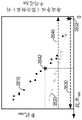
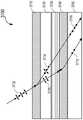
图33A示出了用于不同视场的透射式体布拉格光栅和反射式体布拉格光栅的布拉格峰的线宽。图33B示出了用于不同视场的透射式体布拉格光栅的布拉格峰的示例。图33C示出了用于不同视场的反射式体布拉格光栅的布拉格峰的示例。Figure 33A shows the linewidths of the Bragg peaks of transmissive and reflective VBGs for different fields of view. Figure 33B shows examples of Bragg peaks for transmissive volume Bragg gratings for different fields of view. Figure 33C shows examples of Bragg peaks for reflective volume Bragg gratings for different fields of view.
图34A示出了在多路复用体布拉格光栅的示例中串扰和效率之间的权衡。图34B示出了在多路复用体布拉格光栅的示例中串扰和效率之间的权衡。Figure 34A shows the trade-off between crosstalk and efficiency in the example of multiplexed volume Bragg gratings. Figure 34B shows the trade-off between crosstalk and efficiency in the example of multiplexed volume Bragg gratings.
图35A示出了在多路复用透射式体布拉格光栅中最小衍射效率与总折射率调制和相应串扰之间的关系。图35B示出了在多路复用反射式体布拉格光栅中最小衍射效率与总折射率调制和相应串扰之间的关系。Figure 35A shows the relationship between minimum diffraction efficiency and overall refractive index modulation and corresponding crosstalk in a multiplexed transmissive volume Bragg grating. Figure 35B shows the relationship between minimum diffraction efficiency and overall refractive index modulation and corresponding crosstalk in a multiplexed reflective volume Bragg grating.
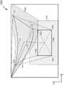
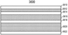
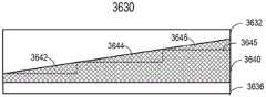
图36A示出了根据某些实施例的包括具有不同厚度的空间复用体布拉格光栅的波导显示器的示例。图36B示出了根据某些实施例的包括具有非均匀厚度的多路复用体布拉格光栅的波导显示器的另一个示例。图36C示出了根据某些实施例的包括具有非均匀厚度的多路复用体布拉格光栅的波导显示器的另一个示例。36A illustrates an example of a waveguide display including spatially multiplexed volume Bragg gratings with different thicknesses, in accordance with certain embodiments. 36B illustrates another example of a waveguide display including a multiplexed volume Bragg grating having a non-uniform thickness in accordance with certain embodiments. 36C illustrates another example of a waveguide display including a multiplexed volume Bragg grating having a non-uniform thickness in accordance with certain embodiments.
图37示出了根据某些实施例的波导显示器的示例,该波导显示器包括两个多路复用体布拉格光栅和在两个多路复用体布拉格光栅之间的偏振转换器。37 shows an example of a waveguide display including two multiplexed volume Bragg gratings and a polarization converter between the two multiplexed volume Bragg gratings, according to some embodiments.
图38示出了根据某些实施例的包括抗反射层和角度选择性透射层的波导显示器的示例。38 illustrates an example of a waveguide display including an anti-reflection layer and an angle-selective transmissive layer in accordance with certain embodiments.
图39是根据某些实施例的近眼显示器的示例中的电子系统的示例的简化框图。39 is a simplified block diagram of an example of an electronic system in an example of a near-eye display according to some embodiments.
附图仅为了说明的目的而描绘本发明的实施例。本领域的技术人员将从以下描述中容易地认识到,在不脱离所附权利要求中限定的本发明的原理或所推崇的益处的情况下,可以采用所示结构和方法的替代实施例。The drawings depict embodiments of the invention for purposes of illustration only. Those skilled in the art will readily appreciate from the following description that alternative embodiments of the structures and methods shown may be employed without departing from the principles of the invention as defined in the appended claims or the benefits advertised.
在附图中,相似的部件和/或特征可以具有相同的附图标记。此外,可以通过在附图标记之后用短划线和在相似部件之间进行区分的第二标记来区分相同类型的多种部件。如果在说明书中仅使用第一附图标记,则该描述适用于具有相同第一附图标记的任何一个相似部件,而与第二附图标记无关。In the drawings, similar components and/or features may have the same reference numerals. Furthermore, various components of the same type may be distinguished by following the reference number with a dash and a second label to distinguish between similar components. If only the first reference number is used in the description, the description applies to any one similar part having the same first reference number irrespective of the second reference number.
发明详述Detailed description of the invention
本发明总体上涉及用于近眼显示系统的基于体布拉格光栅(VBG)的波导显示器。在近眼显示系统中,通常希望扩展视窗、减少显示雾度、提高图像质量(例如,分辨率和对比度)、减小物理尺寸、增加功率效率、并增加视场。在基于波导的近眼显示系统中,投影图像的光可以耦合到波导(例如,透明衬底)中,在波导内传播,并在不同位置处从波导耦合出去,以复制出射光瞳并扩展视窗。可以使用两个或更多个光栅来在两个维度上扩展出射光瞳。在用于增强现实应用的基于波导的近眼显示系统中,来自周围环境的光可以穿过波导显示器的至少透视区域(例如,透明衬底)并到达用户的眼睛。在一些实施方式中,可以使用衍射光学元件(例如光栅)将投影图像的光耦合到波导中或从波导耦合出去。The present invention generally relates to volume Bragg grating (VBG) based waveguide displays for near eye display systems. In near-eye display systems, it is often desirable to expand the viewing window, reduce display haze, improve image quality (eg, resolution and contrast), reduce physical size, increase power efficiency, and increase the field of view. In a waveguide-based near-eye display system, the light of the projected image can be coupled into a waveguide (eg, a transparent substrate), propagate within the waveguide, and couple out of the waveguide at various locations to replicate the exit pupil and expand the viewing window. Two or more gratings can be used to expand the exit pupil in two dimensions. In a waveguide-based near-eye display system for augmented reality applications, light from the surrounding environment can pass through at least a see-through area of the waveguide display (eg, a transparent substrate) and reach the user's eyes. In some embodiments, diffractive optical elements (eg, gratings) may be used to couple the light of the projected image into or out of the waveguide.
由于光栅效率的角度依赖性,使用衍射光学元件实现的光学耦合器可能具有有限的视场。因此,从多个入射角(例如,从不同的视场)入射到耦合器上的光可能不会以相等或相似的效率衍射。此外,使用衍射光学元件实现的耦合器可能导致不同颜色的光之间的色散,并且对于不同颜色的光可能具有不同的衍射角。因此,彩色图像中的不同颜色分量可能无法相互重叠。因此,显示图像的质量(例如,颜色再现中性(color reproductionneutrality))可能会降低。此外,由于光色散和波导显示器能够引导的光的波矢量的有限范围,不同颜色的光的视场可能会减小或部分被截断。为了减少色散并提高视场(FOV)范围和衍射效率,可以使用厚的透射式和/或反射式VBG光栅,其包括许多多路复用光栅以覆盖不同颜色分量的不同视场,这在许多情况下可能是不切实际的,和/或由于光栅的厚度和记录多路复用VBG光栅的大量曝光,可能导致显著的显示和透视雾度。例如,在一些情况下,可能需要厚度大于1毫米的透射式VBG光栅,以减少色散并获得期望的FOV范围和衍射效率。可以使用具有相对较低厚度的反射式VBG光栅来实现期望的性能。然而,对于反射光栅,用于二维光瞳扩展的光栅可能无法重叠,因此波导显示器的物理尺寸可能很大,并且显示雾度可能仍然很大。Optical couplers implemented using diffractive optical elements may have a limited field of view due to the angular dependence of grating efficiency. Therefore, light incident on the coupler from multiple angles of incidence (eg, from different fields of view) may not diffract with equal or similar efficiency. Furthermore, couplers implemented using diffractive optical elements may cause dispersion between different colors of light and may have different diffraction angles for different colors of light. Therefore, different color components in a color image may not overlap each other. Therefore, the quality of the displayed image (eg, color reproduction neutrality) may be degraded. Furthermore, due to light dispersion and the limited range of wave vectors of light that a waveguide display can guide, the field of view for light of different colors may be reduced or partially truncated. To reduce chromatic dispersion and increase field of view (FOV) range and diffraction efficiency, thick transmissive and/or reflective VBG gratings can be used, which include many multiplexed gratings to cover different fields of view for different color components, which are found in many situations may be impractical and/or may result in significant display and see-through haze due to the thickness of the grating and the heavy exposure of the recording multiplexed VBG grating. For example, in some cases, transmissive VBG gratings thicker than 1 mm may be required to reduce dispersion and achieve the desired FOV range and diffraction efficiency. The desired performance can be achieved using a reflective VBG grating with a relatively low thickness. However, with reflective gratings, the gratings used for 2D pupil expansion may not overlap, so the physical size of the waveguide display may be large and the display haze may still be large.
根据某些实施例,具有匹配光栅矢量(例如,在垂直于透明衬底的表面法线方向的平面中具有相同的光栅矢量)的两个VBG光栅(或同一光栅的两个部分)可用于衍射显示光并在一个维度上扩展出射光瞳。由于在两个VBG光栅处的相反布拉格条件(例如+1级和-1级衍射),两个VBG光栅可以补偿由彼此引起的显示光的色散,以降低总色散。因此,可以使用薄的VBG光栅,并且仍然可以获得期望的分辨率。由于色散补偿,薄透射式VBG光栅可以用于实现期望的分辨率,并且用于二维光瞳扩展的光栅可以至少部分重叠,以减小波导显示器的物理尺寸。According to some embodiments, two VBG gratings (or two parts of the same grating) with matching grating vectors (eg, identical grating vectors in a plane perpendicular to the surface normal direction of the transparent substrate) can be used for diffraction Displays the light and expands the exit pupil in one dimension. Due to opposite Bragg conditions (eg +1st and -1st order diffraction) at the two VBG gratings, the two VBG gratings can compensate for the dispersion of the display light caused by each other to reduce the total dispersion. Thus, thin VBG gratings can be used and still obtain the desired resolution. Due to dispersion compensation, thin transmissive VBG gratings can be used to achieve the desired resolution, and the gratings for 2D pupil expansion can be at least partially overlapped to reduce the physical size of the waveguide display.
在一些实施例中,为了在全FOV(full FOV)和颜色光谱上实现期望的FOV、耦合效率和耦合效率均匀性,可以在一个或更多个波导板上形成包括多路复用VBG的多个VBG层。每个VBG层可以用于以相对较高的效率耦合特定FOV和/或颜色范围内的光,并且多个VBG层的组合可以以相对较高且均匀的耦合效率提供所需FOV和颜色范围的完全覆盖。In some embodiments, to achieve desired FOV, coupling efficiency, and coupling efficiency uniformity across the full FOV and color spectrum, multiplexed VBGs including multiplexed VBGs may be formed on one or more waveguide plates a VBG layer. Each VBG layer can be used to couple light within a specific FOV and/or color range with relatively high efficiency, and the combination of multiple VBG layers can provide the desired FOV and color range with relatively high and uniform coupling efficiency full coverage.
在一些实施例中,第一对VBG光栅(或光栅的两个部分)可用于在一个维度上扩展出射光瞳并补偿由彼此引起的色散,第二对VBG光栅(或光栅的两个部分)可用于在另一个维度上扩展出射光瞳并可补偿由彼此引起的色散。因此,可以在两个维度上复制出射光瞳,并且显示图像的分辨率在两个维度上都可以很高。In some embodiments, a first pair of VBG gratings (or two parts of a grating) can be used to expand the exit pupil in one dimension and compensate for dispersion caused by each other, a second pair of VBG gratings (or two parts of a grating) Can be used to expand the exit pupil in another dimension and can compensate for chromatic dispersion caused by each other. Thus, the exit pupil can be replicated in two dimensions, and the resolution of the displayed image can be high in both dimensions.
透射式VBG的布拉格峰和旁瓣的全宽半幅(FWHM)角度范围可以随着相应的视场而增加。VBG也可以衍射来自不同相应视场的不同颜色的光。因此,对于不同颜色的光,VBG可能具有不同的FWHM角度范围。例如,VBG可以衍射来自较大视场的蓝光和来自较小视场的红光,因此相比于红光,对于蓝光具有更宽的FWHM角度范围。当一个VBG的衍射效率曲线与另一个VBG的衍射效率曲线部分重叠时,由于串扰,一些显示光可能被光栅以不期望的衍射角不期望地衍射,导致重影图像(ghost image)或其他光学伪像。为了避免来自大视场(例如正视场)的蓝光的串扰,透射式VBG可以在多路复用光栅中被松散地复用,这可以降低来自小视场(例如负视场)的红光的覆盖范围和整体衍射效率。因此,基于透射式VBG的波导显示器的整体效率可能受到串扰的限制。The full width at half maximum (FWHM) angular range of the Bragg peak and side lobes of the transmissive VBG can increase with the corresponding field of view. VBGs can also diffract light of different colors from different corresponding fields of view. Therefore, for different colors of light, the VBG may have different FWHM angle ranges. For example, a VBG can diffract blue light from a larger field of view and red light from a smaller field of view, and thus has a wider FWHM angular range for blue light than for red light. When the diffraction efficiency curve of one VBG partially overlaps the diffraction efficiency curve of another VBG, some display light may be undesirably diffracted by the grating at undesired diffraction angles due to crosstalk, resulting in ghost images or other optical Artifacts. To avoid crosstalk of blue light from large fields of view (e.g. positive field), transmissive VBGs can be loosely multiplexed in a multiplexing grating, which can reduce the coverage of red light from small fields of view (e.g. negative field) range and overall diffraction efficiency. Therefore, the overall efficiency of a transmissive VBG-based waveguide display may be limited by crosstalk.
根据某些实施例,为了提高透射光栅的衍射效率而不增加串扰,同时提供期望的FOV,光栅耦合器可以包括具有不同厚度的透射式VBG。例如,为了衍射来自大视场(例如正视场)的蓝光,全息材料层可以具有更高的厚度,以减小记录在其中的光栅的线宽,使得更多的光栅可以在全息材料层中被复用,而不会增加串扰。对于来自小视场(例如负视场)的红光,增加全息材料层的厚度也可以减小线宽,但是速率低于来自大视场的蓝光。因此,其中记录有相对密集复用光栅的较厚全息材料层可以对来自大视场的蓝光具有期望的串扰性能,并且对来自小视场的红光也具有高衍射效率。对于来自小视场的红光、绿光和蓝光,透射式VBG的线宽可能彼此相对接近。因此,较薄的全息材料层可用于在其中记录透射光栅,以衍射来自较小视场的显示光。透射式VBG可以被复用,以实现对于来自较小视场的显示光的高效率,而不会引起多路复用VBG之间的衍射串扰,该衍射串扰可能导致重影图像或其他光学伪像。According to some embodiments, in order to increase the diffraction efficiency of the transmission grating without increasing crosstalk, while providing the desired FOV, the grating coupler may include transmissive VBGs having different thicknesses. For example, in order to diffract blue light from a large field of view (eg, frontal field of view), the holographic material layer can have a higher thickness to reduce the linewidth of the grating recorded therein, so that more gratings can be captured in the holographic material layer multiplexing without increasing crosstalk. For red light from a small field of view (eg, negative field of view), increasing the thickness of the holographic material layer can also reduce the linewidth, but at a lower rate than blue light from a large field of view. Thus, a thicker layer of holographic material in which a relatively densely multiplexed grating is recorded can have desirable crosstalk performance for blue light from a large field of view, and also high diffraction efficiency for red light from a small field of view. For red, green, and blue light from small fields of view, the linewidths of transmissive VBGs may be relatively close to each other. Thus, thinner layers of holographic material can be used to record transmission gratings therein to diffract display light from a smaller field of view. Transmissive VBGs can be multiplexed to achieve high efficiency for display light from a smaller field of view without causing diffractive crosstalk between the multiplexed VBGs that can lead to ghost images or other optical artifacts picture.
在一个示例中,波导显示器可以包括波导和至少一个光栅耦合器,该光栅耦合器被配置为将显示光耦合到波导中或从波导耦合出去。光栅耦合器可以包括排列成叠层的多个光栅层。多个光栅层中的每个光栅层可以具有不同的相应厚度,并且可以包括透射式VBG,用于衍射来自不同相应视场的特定波长的显示光。具有较高厚度的光栅层可以用于衍射来自较大视场的特定波长的显示光。具有较低厚度的光栅层可以用于衍射来自较小视场的特定波长的显示光。In one example, a waveguide display can include a waveguide and at least one grating coupler configured to couple display light into or out of the waveguide. The grating coupler may include a plurality of grating layers arranged in a stack. Each of the plurality of grating layers may have a different respective thickness and may include a transmissive VBG for diffracting specific wavelengths of display light from different respective fields of view. Grating layers with higher thicknesses can be used to diffract specific wavelengths of display light from a larger field of view. Grating layers with lower thicknesses can be used to diffract specific wavelengths of display light from a smaller field of view.
例如,光栅层可以在叠层中至少包括第一光栅层和第二光栅层。第一光栅层可以以第一厚度为特征,并且可以包括第一透射式VBG,该第一透射式VBG被配置为衍射来自第一视场(例如负视场)的第一波长的显示光(例如蓝光)。第二光栅层可以以大于第一厚度的第二厚度为特征,并且可以包括第二透射式VBG,该第二透射式VBG被配置为衍射来自大于第一视场的第二视场(例如正视场)的第一波长的显示光。第一透射式VBG可以进一步被配置为衍射来自比第一视场小的第三视场的比第一波长长的第二波长的显示光(例如,红光)。第二透射式VBG可以进一步被配置为衍射来自小于第二视场的第四视场的第二波长的显示光。第一光栅层可以包括第一多路复用VBG,该第一多路复用VBG包括以第一多次全息记录曝光所记录的第一多个透射式VBG。第二光栅层可以包括第二多路复用VBG,该第二多路复用VBG包括以第二多次全息记录曝光所记录的第二多个透射式VBG。第一光栅层和第二光栅层可以由对可见光透明的衬底分开。For example, the grating layer may include at least a first grating layer and a second grating layer in the stack. The first grating layer may be characterized by a first thickness, and may include a first transmissive VBG configured to diffract display light at a first wavelength from a first field of view (eg, a negative field of view) such as Blu-ray). The second grating layer can be characterized by a second thickness that is greater than the first thickness, and can include a second transmissive VBG configured to diffract from a second field of view (eg, front view) that is greater than the first field of view field) of the display light of the first wavelength. The first transmissive VBG may be further configured to diffract display light (eg, red light) of a second wavelength longer than the first wavelength from a third field of view that is smaller than the first field of view. The second transmissive VBG may be further configured to diffract display light at a second wavelength from a fourth field of view that is smaller than the second field of view. The first grating layer may include a first multiplexed VBG including a first plurality of transmissive VBGs recorded with a first plurality of holographic recording exposures. The second grating layer may include a second multiplexed VBG including a second plurality of transmissive VBGs recorded with a second plurality of holographic recording exposures. The first grating layer and the second grating layer may be separated by a visible light transparent substrate.
根据某些实施例,波导显示器可以包括波导和至少一个光栅耦合器,该光栅耦合器被配置为将显示光耦合到波导中或从波导耦合出去。光栅耦合器可以包括以非均匀厚度为特征的光栅层。透射式VBG可以被记录在具有不同厚度的光栅层的不同区域中,以如上所述衍射来自不同视场的显示光。具有非均匀厚度的光栅层可以通过在具有非均匀厚度的衬底上涂覆全息材料层来形成,或者通过在具有均匀厚度的衬底上涂覆全息材料层并且使用不均匀光图案选择性地减敏全息材料层的部分来形成。According to some embodiments, a waveguide display may include a waveguide and at least one grating coupler configured to couple display light into or out of the waveguide. The grating coupler may include a grating layer characterized by a non-uniform thickness. Transmissive VBGs can be recorded in different regions of grating layers with different thicknesses to diffract display light from different fields of view as described above. A grating layer with a non-uniform thickness can be formed by coating a layer of holographic material on a substrate with a non-uniform thickness, or by coating a layer of holographic material on a substrate with a uniform thickness and selectively using a non-uniform light pattern A portion of the desensitized holographic material layer is formed.
在以下描述中,描述了各种发明实施例,包括设备、系统、方法等。为了解释的目的,阐述了具体细节以便提供对本公开内容的实例的透彻理解。然而,将明显的是,在没有这些具体细节的情况下可以实施各种示例。例如,设备、系统、结构、组件、方法和其他部件可以以框图形式被示出为部件,以避免在不必要的细节上模糊示例。在其他情况下,熟知的设备、过程、系统、结构和技术可以在没有必要细节的情况下被示出,以便避免模糊示例。附图和描述不意图是限制性的。在本公开内容中使用的术语和表述被用作描述性术语而非限制性的术语,并且在使用这样的术语和表述时不意图排除所示出和描述的特征或其部分的任何等同物。词语“示例”在本文中用于表示“用作示例、实例或说明”。本文描述为“示例”的任何实施例或设计不一定被解释为比其他实施例或设计更优选或更有利。In the following description, various inventive embodiments are described, including devices, systems, methods, and the like. For the purpose of explanation, specific details are set forth in order to provide a thorough understanding of the examples of the present disclosure. It will be apparent, however, that various examples may be practiced without these specific details. For example, devices, systems, structures, components, methods, and other components may be shown as components in block diagram form in order to avoid obscuring the examples in unnecessary detail. In other instances, well-known devices, procedures, systems, structures and techniques may be shown without necessary detail in order to avoid obscuring examples. The drawings and description are not intended to be limiting. The terms and expressions used in this disclosure are to be used as terms of description rather than limitation, and such terms and expressions are not intended to exclude any equivalents of the illustrated and described features or parts thereof. The word "example" is used herein to mean "serving as an example, instance, or illustration." Any embodiment or design described herein as an "example" is not necessarily to be construed as preferred or advantageous over other embodiments or designs.
图1是根据某些实施例的包括近眼显示器120的人工现实系统环境100的示例的简化框图。图1所示的人工现实系统环境100可以包括近眼显示器120、可选的外部成像设备150和可选的输入/输出接口140,它们中的每一个都可以耦合到可选的控制台110。尽管图1示出了包括一个近眼显示器120、一个外部成像设备150和一个输入/输出接口140的人工现实系统环境100的示例,但是在人工现实系统环境100中可以包括任意数量的这些部件,或者可以省略这些部件中的任何部件。例如,可以有多个近眼显示器120,这些近眼显示器120由与控制台110通信的一个或更多个外部成像设备150监控。在一些配置中,人工现实系统环境100可以不包括外部成像设备150、可选的输入/输出接口140和可选的控制台110。在替代配置中,人工现实系统环境100中可以包括不同或附加的部件。1 is a simplified block diagram of an example of an artificial
近眼显示器120可以是向用户呈现内容的头戴式显示器。由近眼显示器120呈现的内容的示例包括以下中的一个或更多个:图像、视频、音频或它们的任何组合。在一些实施例中,音频可以经由外部设备(例如,扬声器和/或耳机)进行呈现,该外部设备从近眼显示器120、控制台110或近眼显示器120和控制台110两者接收音频信息并基于音频信息呈现音频数据。近眼显示器120可以包括一个或更多个刚性主体,该刚性主体可以刚性或非刚性地彼此联接。刚性主体之间的刚性联接可以使所联接的刚性主体充当单个刚性实体。刚性主体之间的非刚性联接可以允许刚性主体相对于彼此移动。在各种实施例中,近眼显示器120可以以任何合适的形状因子(包括一副眼镜)来被实现。下面参照图2和图3进一步描述近眼显示器120的一些实施例。附加地,在各种实施例中,本文描述的功能可以用在头戴式装置中,该头戴式装置组合近眼显示器120外部环境的图像和人工现实内容(例如,计算机生成的图像)。因此,近眼显示器120可以用生成的内容(例如,图像、视频、声音等)来增强近眼显示器120外部的物理、现实世界环境的图像,以向用户呈现增强现实。The near-
在各种实施例中,近眼显示器120可以包括显示电子器件122、显示光学器件124和眼睛跟踪单元130中的一个或更多个。在一些实施例中,近眼显示器120还可以包括一个或更多个定位器126、一个或更多个位置传感器128和惯性测量单元(IMU)132。在各种实施例中,近眼显示器120可以省略以下中的任何一个:眼睛跟踪单元130、定位器126、位置传感器128和IMU 132,或者包括附加元件。附加地,在一些实施例中,近眼显示器120可以包括组合了结合图1描述的各种元件的功能的元件。In various embodiments, near-
显示电子器件122可以根据从例如控制台110接收的数据向用户显示图像或促进图像的显示。在各种实施例中,显示电子器件122可以包括一个或更多个显示面板,诸如液晶显示器(LCD)、有机发光二极管(OLED)显示器、无机发光二极管(ILED)显示器、微发光二极管(μLED)显示器、有源矩阵OLED显示器(AMOLED)、透明OLED显示器(TOLED)或某种其他显示器。例如,在近眼显示器120的一个实施方式中,显示电子器件122可以包括前TOLED面板、后显示面板以及在前显示面板和后显示面板之间的光学部件(例如,衰减器、偏振器或者衍射膜或光谱膜)。显示电子器件122可以包括发射例如红色、绿色、蓝色、白色或黄色的主要颜色(predominant color)的光的像素。在一些实施方式中,显示电子器件122可以通过由二维面板产生的立体效果来显示三维(3D)图像,以创建图像深度的主观感知。例如,显示电子器件122可以包括分别位于用户的左眼和右眼前方的左显示器和右显示器。左显示器和右显示器可以呈现相对于彼此水平偏移的图像的副本,以产生立体效果(例如,观看图像的用户对图像深度的感知)。
在某些实施例中,显示光学器件124可以(例如,使用光波导和耦合器)光学地显示图像内容,或者放大从显示电子器件122接收的图像光,校正与图像光相关联的光学误差,并将校正后的图像光呈现给近眼显示器120的用户。在各种实施例中,显示光学器件124可以包括一个或更多个光学元件,例如衬底、光波导、光圈(aperture)、费涅尔透镜、凸透镜、凹透镜、滤光器、输入/输出耦合器或者可以影响从显示电子器件122发射的图像光的任何其他合适的光学元件。显示光学器件124可以包括不同光学元件以及机械耦合件的组合,以保持组合中的光学元件的相对间距和定向。显示光学器件124中的一个或更多个光学元件可以具有光学涂层,例如抗反射涂层、反射涂层、滤光涂层或不同光学涂层的组合。In certain embodiments,
显示光学器件124对图像光的放大可以允许显示电子器件122比更大的显示器物理上更小、重量更轻并且消耗更少的功率。附加地,放大可以增加显示内容的视场。显示光学器件124对图像光的放大倍数可以通过调整光学元件、增加光学元件或从显示光学器件124移除光学元件来改变。在一些实施例中,显示光学器件124可以将显示的图像投影到一个或更多个图像平面,所述图像平面可以比近眼显示器120更远离用户的眼睛。The magnification of the image light by
显示光学器件124还可以被设计为校正一种或更多种类型的光学误差,诸如二维光学误差、三维光学误差或它们的任意组合。二维误差可以包括二维中出现的光学像差(optical aberration)。二维误差的示例类型可以包括桶形失真、枕形失真、纵向色差和横向色差。三维误差可以包括三维中出现的光学误差。三维误差的示例类型可以包括球面像差(spherical aberration)、彗形像差(comatic aberration)、像场弯曲(fieldcurvature)和像散(astigmatism)。
定位器126可以是相对于彼此并相对于近眼显示器120上的参考点位于近眼显示器120上特定位置的对象。在一些实施方式中,控制台110可以识别由外部成像设备150捕获的图像中的定位器126,以确定人工现实头戴式装置的位置、定向或两者。定位器126可以是LED、锥体棱镜(corner cube reflector)、反射标记、与近眼显示器120在其中操作的环境形成对比的一种光源、或者它们的任何组合。在定位器126是有源部件(例如,LED或其他类型的发光器件)的实施例中,定位器126可以发射可见光波段(例如,约380nm至750nm)中的光、红外(IR)波段(例如,约750nm至1mm)中的光、紫外波段(例如,约10nm至约380nm)中的光、电磁波谱的另一部分中的光或电磁波谱中各部分的任意组合中的光。The
外部成像设备150可以包括一个或更多个相机、一个或更多个视频相机、能够捕获包括一个或更多个定位器126的图像的任何其他设备或者它们的任何组合。附加地,外部成像设备150可以包括一个或更多个滤光器(例如,用于提高信噪比)。外部成像设备150可以被配置成检测从外部成像设备150的视场中的定位器126发射或反射的光。在定位器126包括无源元件(例如,回射器(retroreflector))的实施例中,外部成像设备150可以包括照亮一些或所有定位器126的光源,定位器126可以将光回射到外部成像设备150中的光源。可以将慢速校准数据从外部成像设备150传送到控制台110,并且外部成像设备150可以从控制台110接收一个或更多个校准参数,用于调整一个或更多个成像参数(例如,焦距、焦点、帧速率、传感器温度、快门速度、光圈等)。
位置传感器128可以响应于近眼显示器120的运动而生成一个或更多个测量信号。位置传感器128的示例可以包括加速度计、陀螺仪、磁力计、其他运动检测或误差校正传感器、或者它们的任何组合。例如,在一些实施例中,位置传感器128可以包括测量平移运动(例如,向前/向后、向上/向下、或向左/向右)的多个加速度计和测量旋转运动(例如,俯仰、偏航、或滚动)的多个陀螺仪。在一些实施例中,各个位置传感器可以彼此正交定向。
IMU 132可以是基于从一个或更多个位置传感器128接收的测量信号生成快速校准数据的电子器件。位置传感器128可位于IMU 132的外部、IMU 132的内部或它们的任何组合。基于来自一个或更多个位置传感器128的一个或更多个测量信号,IMU 132可以生成快速校准数据,该快速校准数据指示相对于近眼显示器120的初始位置的近眼显示器120的估计位置。例如,IMU 132可以对从加速度计接收的测量信号在时间上进行积分,以估计速度向量,并且对速度向量在时间上进行积分,以确定近眼显示器120上参考点的估计位置。替代地,IMU 132可以向控制台110提供采样的测量信号,控制台110可以确定快速校准数据。虽然参考点通常可以被定义为空间中的点,但是在各种实施例中,参考点也可以被定义为近眼显示器120内的点(例如,IMU 132的中心)。
眼睛跟踪单元130可以包括一个或更多个眼睛跟踪系统。眼睛跟踪可以指确定眼睛相对于近眼显示器120的位置,包括眼睛的定向和位置。眼睛跟踪系统可以包括对一只或更多只眼睛进行成像的成像系统,并且可以可选地包括光发射器,该光发射器可以生成指向眼睛的光,使得由眼睛反射的光可以被成像系统捕获。例如,眼睛跟踪单元130可以包括发射可见光谱或红外光谱中的光的非相干光源或相干光源(例如,激光二极管),以及捕获由用户的眼睛反射的光的照相机。作为另一个示例,眼睛跟踪单元130可以捕获由微型雷达单元发射的反射无线电波。眼睛跟踪单元130可以使用低功率光发射器,其以不会伤害眼睛或引起身体不适的频率和强度发射光。眼睛跟踪单元130可以被布置成提高眼睛跟踪单元130捕获的眼睛图像中的对比度,同时降低眼睛跟踪单元130消耗的总功率(例如,降低由眼睛跟踪单元130中包括的光发射器和成像系统消耗的功率)。例如,在一些实施方式中,眼睛跟踪单元130可以消耗小于100毫瓦的功率。
例如,近眼显示器120可以使用眼睛的取向以进行以下操作:确定用户的瞳孔间距(IPD)、确定注视方向、引入深度线索(例如,模糊用户主视线之外的图像)、收集关于VR媒体中的用户交互的启发信息(heuristics)(例如,根据经受的刺激在任何特定主体、对象或帧上花费的时间)、至少部分地基于至少一只用户眼睛的取向的一些其他功能、或它们的任意组合。因为可以确定用户双眼的定向,所以眼睛跟踪单元130可以确定用户正在看哪里。例如,确定用户凝视的方向可以包括基于所确定的用户左眼和右眼的定向来确定集合点(point of convergence)。集合点可以是用户眼睛的两个视网膜中央凹轴(foveal axis)相交的点。用户注视的方向可以是穿过集合点和用户眼睛瞳孔之间的中点的线的方向。For example, the near-
输入/输出接口140可以是允许用户向控制台110发送动作请求的设备。动作请求可以是执行特定动作的请求。例如,动作请求可以是开始或结束应用,或者是在应用内执行特定动作。输入/输出接口140可以包括一个或更多个输入设备。示例输入设备可以包括键盘、鼠标、游戏控制器、手套、按钮、触摸屏或用于接收动作请求并将接收到的动作请求传送到控制台110的任何其他合适的设备。由输入/输出接口140接收的动作请求可以被传送到控制台110,控制台110可以执行对应于所请求动作的动作。在一些实施例中,输入/输出接口140可以根据从控制台110接收的指令向用户提供触觉反馈。例如,当接收到动作请求时,或者当控制台110已经执行了所请求的动作并将指令传送给输入/输出接口140时,输入/输出接口140可以提供触觉反馈。在一些实施例中,外部成像设备150可以用于跟踪输入/输出接口140,诸如跟踪控制器(其可以包括例如IR光源)或用户的手的位置或定位以确定用户的动作。在一些实施例中,近眼显示器120可以包括一个或更多个成像设备以跟踪输入/输出接口140,诸如跟踪控制器或用户的手的位置或定位以确定用户的运动。Input/
控制台110可以根据从外部成像设备150、近眼显示器120和输入/输出接口140中的一个或更多个接收的信息,向近眼显示器120提供内容以呈现给用户。在图1所示的示例中,控制台110可以包括应用储存器112、头戴式装置跟踪模块114、人工现实引擎116和眼睛跟踪模块118。控制台110的一些实施例可以包括与结合图1描述的模块不同的或附加的模块。下面进一步描述的功能可以以不同于这里描述的方式在控制台110的部件之间分配。
在一些实施例中,控制台110可以包括处理器和存储可由处理器执行的指令的非暂时性计算机可读存储介质。处理器可以包括并行执行指令的多个处理单元。非暂时性计算机可读存储介质可以是任何存储器,诸如硬盘驱动器、可移动存储器、或固态驱动器(例如,闪存或动态随机存取存储器(DRAM))。在各种实施例中,结合图1描述的控制台110的模块可以被编码为非暂时性计算机可读存储介质中的指令,当由处理器执行时,这些指令使得处理器执行下面进一步描述的功能。In some embodiments,
应用储存器112可以存储用于由控制台110执行的一个或更多个应用。应用可以包括一组指令,该组指令当由处理器执行时生成用于呈现给用户的内容。由应用生成的内容可以对经由用户眼睛的移动从用户接收的输入或者从输入/输出接口140接收的输入进行响应。应用的示例可以包括:游戏应用、会议应用、视频回放应用或其他合适的应用。
头戴式装置跟踪模块114可以使用来自外部成像设备150的慢速校准信息来跟踪近眼显示器120的移动。例如,头戴式装置跟踪模块114可以使用来自慢速校准信息的观察到的定位器和近眼显示器120的模型来确定近眼显示器120的参考点的位置。头戴式装置跟踪模块114还可以使用来自快速校准信息的位置信息来确定近眼显示器120的参考点的位置。另外,在一些实施例中,头戴式装置跟踪模块114可以使用快速校准信息、慢速校准信息中的部分或它们的任何组合来预测近眼显示器120的未来位置。头戴式装置跟踪模块114可以向人工现实引擎116提供近眼显示器120的估计或预测的未来位置。The
人工现实引擎116可以在人工现实系统环境100内执行应用,并从头戴式装置跟踪模块114接收近眼显示器120的位置信息、近眼显示器120的加速度信息、近眼显示器120的速度信息、近眼显示器120的预测未来位置或它们的任何组合。人工现实引擎116还可以从眼睛跟踪模块118接收估计的眼睛位置和定向信息。基于接收到的信息,人工现实引擎116可以确定要提供给近眼显示器120用于呈现给用户的内容。例如,如果接收到的信息指示用户已经向左看,则人工现实引擎116可以为近眼显示器120生成反映(mirror)用户眼睛在虚拟环境中的移动的内容。附加地,人工现实引擎116可以响应于从输入/输出接口140接收的动作请求来执行在控制台110上执行的应用内的动作,并且向用户提供指示动作已经被执行的反馈。反馈可以是经由近眼显示器120的视觉或听觉反馈,或者经由输入/输出接口140的触觉反馈。The
眼睛跟踪模块118可以从眼睛跟踪单元130接收眼睛跟踪数据,并基于眼睛跟踪数据确定用户眼睛的位置。眼睛的位置可以包括相对于近眼显示器120或其任何元件的眼睛的定向、位置或两者。因为眼睛的旋转轴根据眼睛在眼窝(socket)中的位置而改变,所以确定眼睛在眼窝中的位置可以允许眼睛跟踪模块118更精确地确定眼睛的定向。The eye-tracking
图2是用于实现本文公开的示例中的一些示例的HMD设备200形式的近眼显示器的示例的透视图。HMD设备200可以是例如VR系统、AR系统、MR系统或它们的任何组合的一部分。HMD设备200可以包括主体220和头带230。图2以透视图示出了主体220的底侧223、前侧225和左侧227。头带230可以具有可调节或可延伸的长度。在HMD设备200的主体220和头带230之间可以有足够的空间,以允许用户将HMD设备200安装到用户的头上。在各种实施例中,HMD设备200可以包括附加的、更少的或不同的部件。例如,在一些实施例中,HMD设备200可以包括例如如以下图3所示的眼镜腿(eyeglass temple)和镜腿末端(temples tips),而不是头带230。2 is a perspective view of an example of a near-eye display in the form of an
HMD设备200可以向用户呈现包括具有计算机生成元素的物理、真实世界环境的虚拟和/或增强视图的媒体。HMD设备200呈现的媒体的示例可以包括图像(例如,二维(2D)或三维(3D)图像)、视频(例如,2D或3D视频)、音频或它们的任何组合。图像和视频可以通过封装在HMD设备200的主体220中的一个或更多个显示组件(图2中未示出)呈现给用户的每只眼睛。在各种实施例中,一个或更多个显示组件可以包括单个电子显示面板或多个电子显示面板(例如,用户的每只眼睛一个显示面板)。例如,电子显示面板的示例可以包括LCD、OLED显示器、ILED显示器、μLED显示器、AMOLED、TOLED、某种其他显示器或它们的任何组合。HMD设备200可以包括两个视窗区域。
在一些实施方式中,HMD设备200可以包括各种传感器(未示出),例如深度传感器、运动传感器、位置传感器和眼睛跟踪传感器。这些传感器中的一些可以使用结构光图案进行感测。在一些实施方式中,HMD设备200可以包括用于与控制台通信的输入/输出接口。在一些实施方式中,HMD设备200可以包括虚拟现实引擎(未示出),该虚拟现实引擎可以在HMD设备200内执行应用,并从各种传感器接收HMD设备200的深度信息、位置信息、加速度信息、速度信息、预测的未来位置或它们的任何组合。在一些实施方式中,由虚拟现实引擎接收的信息可以用于向一个或更多个显示组件产生信号(例如,显示指令)。在一些实施方式中,HMD设备200可以包括定位器(未示出,例如定位器126),定位器相对于彼此和相对于参考点位于主体220上的固定位置。每个定位器可以发射可由外部成像设备检测的光。In some implementations, the
图3是用于实现本文公开的一些示例的一副眼镜形式的近眼显示器300的示例的透视图。近眼显示器300可以是图1的近眼显示器120的具体实施方式,并且可以被配置用作虚拟现实显示器、增强现实显示器和/或混合现实显示器。近眼显示器300可以包括框架305和显示器310。显示器310可以被配置成向用户呈现内容。在一些实施例中,显示器310可以包括显示电子器件和/或显示光学器件。例如,如上参考图1的近眼显示器120所述,显示器310可以包括LCD显示面板、LED显示面板或光学显示面板(例如,波导显示组件)。3 is a perspective view of an example of a near-
近眼显示器300还可以包括框架305上或框架305内的各种传感器350a、350b、350c、350d和350e。在一些实施例中,传感器350a-350e可以包括一个或更多个深度传感器、运动传感器、位置传感器、惯性传感器或环境光传感器。在一些实施例中,传感器350a-350e可以包括一个或更多个图像传感器,其被配置为生成表示不同方向上的不同视场的图像数据。在一些实施例中,传感器350a-350e可以用作输入设备来控制或影响近眼显示器300的显示内容,和/或向近眼显示器300的用户提供交互式VR/AR/MR体验。在一些实施例中,传感器350a-350e也可以用于立体成像。The near-
在一些实施例中,近眼显示器300可以进一步包括一个或更多个照明器330,以将光投射到物理环境中。投射的光可以与不同的频带(例如可见光、红外光、紫外光等)相关联,并且可以服务于各种目的。例如,照明器330可以在黑暗环境中(或者在具有低强度红外光、紫外光等的环境中)投射光,来帮助传感器350a-350e捕获黑暗环境中不同对象的图像。在一些实施例中,照明器330可以用于将特定的光图案投射到环境中的对象上。在一些实施例中,照明器330可以用作定位器,例如上面参考图1描述的定位器126。In some embodiments, the near-
在一些实施例中,近眼显示器300还可以包括高分辨率照相机340。照相机340可以捕获视场中的物理环境的图像。所捕获的图像可以例如由虚拟现实引擎(例如,图1的人工现实引擎116)处理,以将虚拟对象添加到所捕获的图像或者修改所捕获的图像中的物理对象,并且所处理的图像可以由用于AR或MR应用的显示器310显示给用户。In some embodiments, the near-
图4是示出了近眼显示系统中的光学系统400的示例的简化图。光学系统400可以包括图像源410和投影仪光学器件420。在图4所示的示例中,图像源410在投影仪光学器件420的前面。在各种实施例中,图像源410可以位于用户眼睛490的视场之外。例如,可以使用一个或更多个反射器或定向耦合器来偏转来自用户眼睛490的视场之外的图像源的光,以使图像源看起来位于图4所示的图像源410的位置。来自图像源410上的区域(例如,像素或发光器件)的光可以被投影仪光学器件420准直并导向出射光瞳430。因此,在图像源410上不同空间位置处的对象可能看起来是在不同视角(FOV)中的远离用户眼睛490的对象。来自不同视角的准直光然后可以被用户眼睛490的晶状体聚焦到用户眼睛490的视网膜492上的不同位置。例如,光的至少一些部分可以聚焦在视网膜492上的中央凹494上。来自图像源410上的区域并从相同方向入射到用户眼睛490上的准直光线可以聚焦到视网膜492上的相同位置。这样,图像源410的单个图像可以形成在视网膜492上。FIG. 4 is a simplified diagram illustrating an example of an
使用人工现实系统的用户体验可能取决于光学系统的几个特征,包括视场(FOV)、图像质量(例如,角度分辨率)、视窗的大小(以适应眼睛和头部的运动)以及视窗内光线的亮度(或对比度)。视场描述了用户看到的图像的角度范围,通常以一只眼睛(对于单目HMD)或两只眼睛(对于双眼或双目HMD)观察到的度数来度量。人类视觉系统可以具有大约200°(水平)乘130°(垂直)的总双目FOV。为了创建完全沉浸式的视觉环境,需要大的FOV,因为大的FOV(例如,大于约60°)可以提供“在”图像中的感觉,而不仅仅是观看图像。较小的视场也可能排除了一些重要的视觉信息。例如,具有小FOV的HMD系统可以使用手势界面,但是用户可能看不到他们的手在小FOV中来确保他们正在使用正确的运动。另一方面,更宽的视场可能需要更大的显示器或光学系统,这可能会影响使用HMD的尺寸、重量、成本和舒适性。User experience with artificial reality systems may depend on several characteristics of the optical system, including field of view (FOV), image quality (eg, angular resolution), size of the viewing window (to accommodate eye and head motion), and the size of the viewing window. The brightness (or contrast) of light. The field of view describes the angular range of the image the user sees and is usually measured in degrees observed by one eye (for a monocular HMD) or both eyes (for a binocular or binocular HMD). The human visual system may have a total binocular FOV of approximately 200° (horizontal) by 130° (vertical). In order to create a fully immersive visual environment, a large FOV is required because a large FOV (eg, greater than about 60°) can provide a feeling of "being in" the image, rather than just viewing the image. The smaller field of view may also exclude some important visual information. For example, an HMD system with a small FOV can use a gestural interface, but the user may not be able to see their hands in the small FOV to ensure they are using the correct motion. On the other hand, a wider field of view may require a larger display or optical system, which may affect the size, weight, cost and comfort of using an HMD.
分辨率可以指用户看到的显示像素或图像元素的角度大小,或者用户查看和正确解释由像素和/或其他像素成像的对象的能力。对于给定的FOV值,HMD的分辨率可以被指定为图像源上的像素数,由此可以通过将一个方向上的FOV除以图像源上相同方向上的像素数来确定角度分辨率。例如,对于40°的水平FOV和图像源上水平方向上的1080个像素,与和Snellen 20/20人类视觉敏锐度相关联的1弧分分辨率相比,相应的角度分辨率可以是大约2.2弧分。Resolution can refer to the angular size of a display pixel or image element that a user sees, or the user's ability to view and correctly interpret an object imaged by a pixel and/or other pixels. For a given FOV value, the resolution of the HMD can be specified as the number of pixels on the image source, whereby the angular resolution can be determined by dividing the FOV in one direction by the number of pixels in the same direction on the image source. For example, for a horizontal FOV of 40° and 1080 pixels in the horizontal direction on the image source, the corresponding angular resolution may be approximately 2.2 arc minutes compared to the 1 arcmin resolution associated with
在某些情况下,视窗可以是用户眼睛前面的二维框,从该框可以查看来自图像源的显示图像。如果用户的瞳孔移出视窗,用户可能看不到显示的图像。例如,在非光瞳形成配置中,存在观察视窗,在该观察视窗内将有对HMD图像源的无渐晕的观察(unvignettedviewing),并且当用户眼睛的瞳孔在观察视窗之外时,所显示的图像可以渐晕(vignette)或者可以被裁剪(clip),但是仍然是可见的。在光瞳形成配置中,图像在出射光瞳之外可能不可见。In some cases, the viewport may be a two-dimensional box in front of the user's eye from which the displayed image from the image source can be viewed. If the user's pupils move out of the viewport, the user may not see the displayed image. For example, in a non-pupil forming configuration, there is a viewing window within which there will be unvignetted viewing of the HMD image source, and when the pupil of the user's eye is outside the viewing window, the displayed The image can be vignetted or clipped, but still visible. In the pupil forming configuration, the image may not be visible outside the exit pupil.
在视网膜上可以获得最高分辨率的人眼中央凹可以对应于大约2°到大约3°的FOV。这可能需要眼睛旋转,以便以最高分辨率查看离轴对象(off-axis object)。由于眼睛围绕瞳孔后面大约10mm的点旋转,所以眼睛旋转以观看离轴对象会引入瞳孔的平移。此外,用户可能不总是能够将用户眼睛的瞳孔(例如,半径约为2.5mm)精确定位在视窗中的理想位置。此外,使用HMD的环境可能要求视窗更大,以允许用户的眼睛和/或头部相对于HMD移动,例如,当HMD用于移动的车辆中或设计成在用户步行时使用时。这些情况下的移动量可能取决于HMD与用户头部的耦合程度。The fovea of the human eye, where the highest resolution can be obtained on the retina, may correspond to a FOV of about 2° to about 3°. This may require eye rotation to view off-axis objects at the highest resolution. Since the eye rotates around a point approximately 10mm behind the pupil, rotation of the eye to view off-axis objects introduces a translation of the pupil. Furthermore, the user may not always be able to precisely position the pupil of the user's eye (eg, approximately 2.5 mm in radius) at the ideal location in the viewing window. Additionally, the environment in which the HMD is used may require a larger viewing window to allow the user's eyes and/or head to move relative to the HMD, eg, when the HMD is used in a moving vehicle or designed to be used while the user is walking. The amount of movement in these cases may depend on how well the HMD is coupled to the user's head.
因此,为了适应用户瞳孔相对于HMD的移动,HMD的光学系统可能需要提供足够大的出射光瞳或观察视窗,用于以全分辨率观看全FOV。例如,在光瞳形成配置中,对于出射光瞳来说,12mm至15mm的最小尺寸可能是期望的。如果视窗太小,眼睛和HMD之间的微小错位可能导致图像至少部分丢失,用户体验可能会受到严重损害。一般来说,视窗的横向范围比视窗的垂直范围更重要。这可能部分是由于用户之间的眼睛分离距离的显著差异,以及以下事实:眼部佩戴物(eyewear)的未对准倾向于更频繁地发生在横向维度上,并且用户倾向于更频繁地左右调整他们的注视,并且幅度比上下调整注视更大。因此,可以增加视窗横向尺寸的技术可以显著改善用户使用HMD的体验。另一方面,视窗越大,光学器件越大,近眼显示设备可能越重、越笨重。Therefore, to accommodate the movement of the user's pupil relative to the HMD, the optical system of the HMD may need to provide a sufficiently large exit pupil or viewing window for viewing the full FOV at full resolution. For example, in a pupil forming configuration, a minimum size of 12 mm to 15 mm may be desirable for the exit pupil. If the viewing window is too small, a tiny misalignment between the eye and the HMD can result in at least partial loss of the image, and the user experience can be severely compromised. In general, the horizontal extent of the window is more important than the vertical extent of the window. This may be due in part to the significant differences in eye separation distance between users, as well as the fact that eyewear misalignment tends to occur more frequently in the lateral dimension, and users tend to move side to side more frequently Adjust their gaze more widely than up or down. Therefore, techniques that can increase the horizontal size of the window can significantly improve the user's experience with the HMD. On the other hand, the larger the viewing window and the larger the optics, the heavier and bulkier the near-eye display device may be.
为了在明亮的背景下观看显示的图像,AR HMD的图像源可能需要足够亮,并且光学系统可能需要有效地向用户的眼睛提供明亮的图像,使得显示的图像可以在包括强环境光(例如阳光)的背景下可见。HMD的光学系统可以被设计成将光线聚集在视窗中。当视窗较大时,可以使用高功率的图像源来提供在大视窗内可见的明亮图像。因此,在视窗的尺寸、成本、亮度、光学复杂性、图像质量以及光学系统的尺寸和重量之间可能存在权衡。In order to view the displayed image against a bright background, the AR HMD's image source may need to be bright enough, and the optical system may need to effectively provide a bright image to the user's eyes, so that the displayed image can be displayed in environments that include strong ambient light (such as sunlight) ) is visible in the background. The optical system of the HMD can be designed to focus light in the viewing window. When the viewing window is large, a high powered image source can be used to provide a bright image visible within the large viewing window. Thus, there may be trade-offs between window size, cost, brightness, optical complexity, image quality, and size and weight of the optical system.
图5示出了根据某些实施例的包括用于出射光瞳扩展的波导显示器的光学透视增强现实系统500的示例。增强现实系统500可以包括投影仪510和合路器515。投影仪510可以包括光源或图像源512和投影仪光学器件514。在一些实施例中,光源或图像源512可以包括一个或更多个微LED器件。在一些实施方案中,图像源512可以包括显示虚拟对象的多个像素,诸如LCD显示面板或LED显示面板。在一些实施方案中,图像源512可以包括生成相干光或部分相干光的光源。例如,图像源512可以包括激光二极管、垂直腔面发射激光器、LED、超辐射LED(sLED)和/或上述的微LED。在一些实施例中,图像源512可以包括多个光源(例如,上述微LED阵列),每个光源发射对应于原色(primary color)(例如,红色、绿色或蓝色)的单色图像光。在一些实施例中,图像源512可以包括三个微LED二维阵列,其中每个微LED二维阵列可以包括被配置为发射原色(例如,红色、绿色或蓝色)光的微LED。在一些实施例中,图像源512可以包括光学图案生成器,诸如空间光调制器。投影仪光学器件514可以包括一个或更多个光学部件,所述一个或更多个光学部件可以调节来自图像源512的光,诸如扩展、准直、扫描来自图像源512的光或将来自图像源512的光投影到合路器515。一个或更多个光学部件可以包括例如一个或更多个透镜、液体透镜、反射镜、自由形式光学器件、光圈和/或光栅。例如,在一些实施例中,图像源512可以包括微LED的一个或更多个一维阵列或细长的二维阵列,并且投影仪光学器件514可以包括一个或更多个一维扫描器(例如,微反射镜(micro-mirror)或棱镜),该一维扫描器被配置为扫描微LED的一维阵列或细长的二维阵列以生成图像帧。在一些实施方案中,投影仪光学器件514可以包括具有多个电极的液体透镜(例如,液晶透镜),所述电极允许对来自图像源512的光进行扫描。5 illustrates an example of an optical see-through
合路器515可以包括用于将来自投影仪510的光耦合到合路器515的衬底520中的输入耦合器530。输入耦合器530可以包括体全息光栅或另一衍射光学元件(DOE)(例如表面浮雕光栅(SRG))、衬底520的倾斜反射表面或折射耦合器(例如光楔或棱镜)。例如,输入耦合器530可以包括反射式体布拉格光栅或透射式体布拉格光栅。输入耦合器530对于可见光可以具有大于30%、50%、75%、90%或更高的耦合效率。耦合到衬底520中的光可以通过例如全内反射(TIR)在衬底520内传播。衬底520可以是一副眼镜的镜片的形式。衬底520可以具有平坦或弯曲的表面,并且可以包括一种或更多种类型的介电材料,例如玻璃、石英、塑料、聚合物、聚甲基丙烯酸甲酯(PMMA)、晶体、陶瓷等。衬底的厚度可以在例如从小于约1mm至约10mm或更大的范围内。衬底520对可见光可以是透明的。The
衬底520可以包括或可以耦合到多个输出耦合器540,每个输出耦合器540被配置为从衬底520提取由衬底520引导并在衬底520内传播的光的至少一部分,并且将提取的光560引导到视窗595,当增强现实系统500被使用时,增强现实系统500的用户的眼睛590可以位于视窗595处。多个输出耦合器540可以复制出射光瞳以增加视窗595的尺寸,使得显示的图像可以在更大的区域中可见。与输入耦合器530一样,输出耦合器540可以包括光栅耦合器(例如,体全息光栅或表面浮雕光栅)、其他衍射光学元件(DOE)、棱镜等。例如,输出耦合器540可以包括反射式体布拉格光栅或透射式体布拉格光栅。输出耦合器540在不同位置可以具有不同的耦合(例如衍射)效率。衬底520还可以允许来自合路器515前面的环境的光550以很少的损失或没有损失地穿过。输出耦合器540也可以允许光550以很少的损失穿过。例如,在一些实施方式中,输出耦合器540对于光550可以具有非常低的衍射效率,使得光550可以被折射或者以其他方式以很少的损失穿过输出耦合器540,并且因此可以具有比所提取的光560更高的强度。在一些实施方式中,输出耦合器540对光550可以具有高衍射效率,并且可以在某些期望的方向上(即,衍射角)以很少的损失衍射光550。结果,用户可以观看合路器515前面的环境和由投影仪510投影的虚拟对象的图像的组合图像。在一些实施方式中,输出耦合器540对光550可以具有高衍射效率,并且可以以很少的损失将光550衍射到某些期望的方向(例如,衍射角)。The
在一些实施例中,投影仪510、输入耦合器530和输出耦合器540可以在衬底520的任何一侧。输入耦合器530和输出耦合器540可以是反射光栅(reflective grating)(也称为反射光栅(reflection grating))或透射光栅(transmissive grating)(也称为透射光栅(transmission grating)),以将显示光耦合到衬底520中或从衬底520耦合出去。In some embodiments,
图6示出了根据某些实施例的包括用于出射光瞳扩展的波导显示器的光学透视增强现实系统600的示例。增强现实系统600可以类似于增强现实系统500,并且可以包括波导显示器和投影仪,其可以包括光源或图像源612和投影仪光学器件614。波导显示器可以包括衬底630、输入耦合器640和多个输出耦合器650,如以上关于增强现实系统500所述。虽然图5仅示出了来自单个视场的光的传播,但是图6示出了来自多个视场的光的传播。6 illustrates an example of an optical see-through
图6示出了出射光瞳被输出耦合器650复制以形成聚集的出射光瞳或视窗,其中不同的视场(例如,图像源612上的不同像素)可以与朝向视窗的不同的相应传播方向相关联,并且来自相同视场(例如,图像源612上的相同像素)的光对于不同的单独出射光瞳可以具有相同的传播方向。因此,图像源612的单个图像可以由位于视窗中任何位置的用户眼睛形成,其中来自不同单独出射光瞳并且在相同方向传播的光可以来自图像源612上的相同像素,并且可以聚焦到用户眼睛视网膜上的相同位置。图6示出了即使用户的眼睛移动到视窗中的不同位置,图像源的图像也可以被用户的眼睛看到。6 shows that the exit pupil is replicated by
在许多基于波导的近眼显示系统中,为了在两个维度上扩展基于波导的近眼显示器的视窗,可以使用两个或更多个输出光栅来在两个维度上或沿着两个轴扩展显示光(这可以被称为双轴光瞳扩展)。两个光栅可以具有不同的光栅参数,使得一个光栅可以用于在一个方向上复制出射光瞳,而另一个光栅可以用于在另一个方向上复制出射光瞳。In many waveguide-based near-eye display systems, to expand the viewing window of the waveguide-based near-eye display in two dimensions, two or more output gratings can be used to expand the display light in two dimensions or along two axes (This may be referred to as biaxial pupil dilation). The two gratings can have different grating parameters such that one grating can be used to replicate the exit pupil in one direction and the other grating can be used to replicate the exit pupil in the other direction.
如上所述,上述输入和输出光栅耦合器可以是体全息光栅或表面浮雕光栅,它们可以具有非常不同的Klein-Cook参数Q:As mentioned above, the above input and output grating couplers can be volume holographic gratings or surface relief gratings, which can have very different Klein-Cook parameters Q:

其中d是光栅的厚度,λ是自由空间中入射光的波长,Λ是光栅周期,n是记录介质的折射率。Klein-Cook参数Q可以将光栅的光衍射分为三种情况(regime)。当光栅以Q<<1为特征时,光栅的光衍射可以被称为拉曼-纳斯(Raman-Nath)衍射,其中对于法向和/或倾斜入射光可以出现多个衍射级。当光栅以Q>>1(例如,Q≥10)为特征时,光栅的光衍射可被称为布拉格衍射,其中对于以满足布拉格条件的角度入射到光栅上的光,通常仅出现零级和±1级衍射。当光栅以Q≈1为特征时,光栅的衍射可以在拉曼-纳斯衍射和布拉格衍射之间。为了满足布拉格条件,光栅的厚度d可以高于某些值以占据介质的体积(而不是表面),因此可以被称为体布拉格光栅。VBG通常可以具有相对小的折射率调制(例如,Δn≤0.05)以及高的光谱和角度选择性,而表面浮雕光栅通常可以具有大的折射率调制(例如,Δn≥0.5)以及宽的光谱和角度带宽。where d is the thickness of the grating, λ is the wavelength of the incident light in free space, Λ is the grating period, and n is the refractive index of the recording medium. The Klein-Cook parameter Q can divide the light diffraction of the grating into three regimes. When the grating is characterized by Q<<1, the diffraction of light by the grating may be referred to as Raman-Nath diffraction, where multiple diffraction orders may occur for normal and/or obliquely incident light. When the grating is characterized by Q >> 1 (eg, Q ≥ 10), the diffraction of light by the grating may be referred to as Bragg diffraction, where for light incident on the grating at angles satisfying the Bragg condition, typically only the zeroth order and ±1st order diffraction. When the grating is characterized by Q≈1, the diffraction of the grating can be between Raman-Nas diffraction and Bragg diffraction. In order to satisfy the Bragg condition, the thickness d of the grating can be above some value to occupy the volume of the medium (rather than the surface) and thus can be called a volume Bragg grating. VBGs can typically have relatively small refractive index modulations (eg, Δn ≤ 0.05) and high spectral and angular selectivity, while surface relief gratings can typically have large refractive index modulations (eg, Δn ≥ 0.5) and broad spectral and angular selectivities angular bandwidth.
图7A示出了体布拉格光栅(例如反射式VBG)的示例的光谱带宽和表面浮雕光栅(例如透射式SRG)的示例的光谱带宽。横轴表示入射可见光的波长,并且纵轴对应于衍射效率。如曲线710所示,反射式VBG的衍射效率在诸如绿光的窄波长范围内较高。相反,如曲线720所示,透射式SRG的衍射效率在诸如从蓝光到红光的非常宽的波长范围内可以较高。7A shows the spectral bandwidth of an example of a volume Bragg grating (eg, reflective VBG) and the spectral bandwidth of an example of a surface relief grating (eg, transmissive SRG). The horizontal axis represents the wavelength of incident visible light, and the vertical axis corresponds to the diffraction efficiency. As shown by
图7B示出了体布拉格光栅(例如反射式VBG)的示例的角度带宽和表面浮雕光栅(例如透射式SRG)的示例的角度带宽。横轴表示入射到光栅上的可见光的入射角,并且纵轴对应于衍射效率。如曲线715所示,反射式VBG的衍射效率对于从窄角度范围(例如从完美布拉格条件大约±2.5°)入射到光栅上的光是高的。相反,透射式SRG的衍射效率在非常宽的角度范围(例如大于约±10°或更宽)内很高,如曲线725所示。7B shows the angular bandwidth of an example of a volume Bragg grating (eg, reflective VBG) and the angular bandwidth of an example of a surface relief grating (eg, transmissive SRG). The horizontal axis represents the incident angle of visible light incident on the grating, and the vertical axis corresponds to the diffraction efficiency. As shown by
由于在布拉格条件下的高光谱选择性,VBG(例如反射式VBG)可以允许单波导设计而没有原色之间的串扰,并且可以表现出优异的透视质量。然而,光谱和角度选择性可能导致较低的效率,因为在全FOV中只有一部分显示光可能被衍射并到达用户的眼睛。Due to the high spectral selectivity under Bragg conditions, VBGs (eg, reflective VBGs) can allow single-waveguide designs without crosstalk between primary colors and can exhibit excellent see-through quality. However, spectral and angular selectivity may lead to lower efficiency, as only a portion of the display light may be diffracted and reach the user's eye in full FOV.
图8A示出了根据某些实施例的光学透视增强现实系统的示例,该系统包括波导显示器800和用于出射光瞳扩展的表面浮雕光栅。波导显示器800可以包括衬底810(例如波导),其可以类似于衬底520。衬底810可以对可见光透明,并且可以包括例如玻璃、石英、塑料、聚合物、PMMA、陶瓷或晶体衬底。衬底810可以是平坦的衬底或弯曲的衬底。衬底810可以包括第一表面812和第二表面814。显示光可以通过输入耦合器820耦合到衬底810中,并且可以通过全内反射被第一表面812和第二表面814反射,使得显示光可以在衬底810内传播。如上所述,输入耦合器820可以包括光栅、折射耦合器(例如,光楔或棱镜)或反射耦合器(例如,相对于衬底810具有倾斜角的反射表面)。例如,在一个实施例中,输入耦合器820可以包括棱镜,该棱镜可以以相同的折射角将不同颜色的显示光耦合到衬底810中。在另一个示例中,输入耦合器820可以包括光栅耦合器,该光栅耦合器可以在不同方向上将不同颜色的光衍射到衬底810中。对于可见光,输入耦合器820可以具有大于10%、20%、30%、50%、75%、90%或更高的耦合效率。8A illustrates an example of an optical see-through augmented reality system including a
波导显示器800还可以包括位于衬底810的一个或两个表面(例如,第一表面812和第二表面814)上的第一光栅830和第二光栅840,用于在两个维度上扩展入射显示光束,以便用显示光填充视窗(或输出或出射光瞳)。第一光栅830可以被配置为沿着一个方向,例如大约在x方向,扩展至少一部分显示光束。耦合到衬底810中的显示光可以沿线832所示的方向传播。当显示光在衬底810内沿着线832所示的方向传播时,每次在衬底810内传播的显示光到达第一光栅830时,显示光的一部分可以被第一光栅830的一部分衍射向第二光栅840,如线834所示。然后,第二光栅840可以通过每次在衬底810内传播的显示光到达第二光栅840时将显示光的一部分衍射到视窗,在不同的方向(例如,大约在y方向)上扩展来自第一光栅830的显示光。在第二光栅840上,出射区域(exit region)850代表这样的区域,在该区域中,在视窗中的一个光瞳位置(例如,在视窗的中心)处的全FOV的显示光可以从波导显示器800耦合出去。
图8B示出了包括二维复制出射光瞳的视窗的示例。图8B示出了单个输入光瞳805可以被第一光栅830和第二光栅840复制,以形成包括单个出射光瞳852的二维阵列的聚集出射光瞳860。例如,出射光瞳可以通过第一光栅830在大约x方向上复制,并且通过第二光栅840在大约y方向上复制。如上所述,来自单个出射光瞳852并沿相同方向传播的输出光可以聚焦到用户眼睛视网膜中的相同位置。因此,用户的眼睛可以从单个出射光瞳852的二维阵列中的输出光形成单个图像。FIG. 8B shows an example of a window including a two-dimensionally replicated exit pupil. FIG. 8B shows that a
图9A示出了由用于波导显示器中的出射光瞳扩展和多种颜色的出射光瞳的表面浮雕光栅的示例衍射的光的波矢量。圆910可以表示可以由波导引导的光的波矢量。对于波矢量在圆910之外的光,光可能变得倏逝(evanescent)。圆920可以表示由于不满足全内反射条件而可能从波导泄漏出的光的波矢量。因此,圆910和圆920之间的环可以表示可以由波导引导并且可以通过TIR在波导内传播的光的波矢量。波矢量932示出了由输入光栅引起的光色散,其中不同颜色的光可以具有不同的波矢量和不同的衍射角。波矢量942示出了由前光栅(例如,第一光栅830)引起的光色散,其中不同颜色的光可以具有不同的衍射角。波矢量952示出了由后光栅(例如,第二光栅840)引起的光色散,其中不同颜色的光可以具有不同的衍射角。每种颜色的波矢量可以形成各自的闭合三角形,并且不同颜色的三角形可以共享公共的原点顶点922。因此,三个光栅的总色散可以接近于零。9A shows the wave vector of light diffracted by an example of a surface relief grating used for exit pupil expansion and multi-color exit pupils in a waveguide display.
即使三个光栅的总色散可以为零,每个光栅的色散可能会导致波导显示器的视场减小或截断,这是由于如圆910和圆920之间的环所示的波导可以引导光的条件。例如,对于FOV 924,由于输入光栅的色散,由输入光栅衍射后的FOV的覆盖区(footprint)对于不同的颜色可能不同。在图9A所示的示例中,用于第一颜色的光的FOV的覆盖区936可能位于环中,而用于第二颜色的光的FOV的覆盖区934的一部分和用于第三颜色的光的FOV的覆盖区938的一部分可能落在环的外部,因此不会被波导引导。此外,在被前光栅衍射之后,FOV的覆盖区可能被进一步截断或减少。在图9A所示的示例中,用于第一颜色的光的FOV的覆盖区946的一小部分、用于第二颜色的光的FOV的覆盖区944的大部分、以及用于第三颜色的光的FOV的覆盖区948的大部分可能落在环的外部,因此不会被波导引导并且不会被后光栅衍射以到达出射光瞳。Even though the total dispersion of the three gratings may be zero, the dispersion of each grating may result in a reduction or truncation of the field of view of the waveguide display due to the fact that the waveguide as shown by the ring between
图9B通过波导显示器中用于出射光瞳扩展的表面浮雕光栅的示例示出了视场截断。例如,被后光栅衍射后的第一颜色光的FOV可以由覆盖区956示出,覆盖区956可以接近全FOV。对于第二颜色的光,FOV的顶部可能在被第一光栅衍射之后被截断,并且FOV的右侧部分可能在被前光栅衍射之后被截断。因此,被后光栅衍射后的第二颜色光的FOV可以由覆盖区954示出,该覆盖区954可以比全FOV小得多。类似地,对于第三颜色的光,FOV的底部可能在被第一光栅衍射之后被截断,并且FOV的左侧部分可能在被前光栅衍射之后被截断。因此,被后光栅衍射后的第三颜色光的FOV可以由覆盖区958示出,该覆盖区958可以比全FOV小得多。因此,对于某些视场,图像的某些颜色分量可能会丢失。这样,为了实现不同颜色的全FOV,可以使用两个或更多个波导和相应的光栅。此外,如上所述,SRG的宽带宽可能导致不同原色和/或来自不同FOV的光之间的串扰,因此也可以使用多个波导来避免串扰。Figure 9B shows the field of view cut-off with an example of a surface relief grating for exit pupil expansion in a waveguide display. For example, the FOV of the first color light diffracted by the rear grating can be shown by
由于布拉格条件下的高光谱选择性,VBG(例如反射式VBG)可以允许单波导设计,而没有体布拉格光栅中原色之间的串扰,并且可以实现优异的透视质量。因此,输入耦合器530或640以及输出耦合器540或650可以包括体布拉格光栅,其可以是通过将全息记录材料暴露于由两个或更多个相干光束之间的干涉产生的光图案而记录在全息记录材料中的体全息图。在体布拉格光栅中,入射光的入射角和波长可能需要满足布拉格相位匹配条件,以便入射光被布拉格光栅衍射。当在基于波导的近眼显示器中使用单个布拉格光栅时,体布拉格光栅的光谱和角度选择性可能导致较低的效率,因为只有一部分显示光可以被衍射并到达用户的眼睛,并且基于波导的近眼显示器的视场和工作波长范围可能受到限制。在一些实施例中,多路复用VBG可用于提高效率并增加FOV。Due to the high spectral selectivity under Bragg conditions, VBGs (eg, reflective VBGs) can allow single-waveguide designs without crosstalk between primary colors in volume Bragg gratings and can achieve excellent see-through quality. Thus, the
图10A示出了根据某些实施例的基于体布拉格光栅的波导显示器1000的示例的前视图。波导显示器1000可以包括衬底1010,其可以类似于衬底520。衬底1010可以对可见光透明,并且可以包括例如玻璃、石英、塑料、聚合物、PMMA、陶瓷或晶体衬底。衬底1010可以是平坦的衬底或弯曲的衬底。衬底1010可以包括第一表面1012和第二表面1014。显示光可以通过输入耦合器1020耦合到衬底1010中,并且可以通过全内反射被第一表面1012和第二表面1014反射,使得显示光可以在衬底1010内传播。如上所述,输入耦合器1020可以包括衍射耦合器(例如,体全息光栅或表面浮雕光栅)、折射耦合器(例如,光楔或棱镜)或反射耦合器(例如,相对于衬底1010具有倾斜角的反射表面)。例如,在一个实施例中,输入耦合器1020可以包括棱镜,该棱镜可以以相同的折射角将不同颜色的显示光耦合到衬底1010中。在另一个示例中,输入耦合器可以包括光栅耦合器,该光栅耦合器可以在不同方向上将不同颜色的光衍射到衬底1010中。10A illustrates a front view of an example of a volume Bragg grating based
波导显示器1000还可以包括位于衬底1010的一个或两个表面(例如,第一表面1012和第二表面1014)上的第一光栅1030和第二光栅1040,用于在两个维度上扩展入射显示光束,以便用显示光填充视窗。第一光栅1030可以包括一个或更多个多路复用体布拉格光栅,每个光栅被配置为沿着一个方向扩展显示光束的至少一部分(例如,对应于特定视场和/或波长范围的光),如线1032、1034和1036所示。例如,当显示光在衬底1010内沿着线1032、1034或1036所示的方向传播时,每次在衬底1010内传播的显示光到达第一光栅1030时,显示光的一部分可以被第一光栅1030衍射到第二光栅1040。然后,第二光栅1040可以通过每次在衬底1010内传播的显示光到达第二光栅1040时将一部分显示光衍射到视窗,在不同的方向上扩展来自第一光栅1030的显示光。在第二光栅1040上,出射区域1050代表这样的区域,在该区域中,在视窗中的一个光瞳位置(例如,在视窗的中心)处的全FOV的显示光可以从波导显示器1000耦合出去。The
如上所述,第一光栅1030和第二光栅1040可以各自包括多路复用VBG,该多路复用VBG包括多个VBG,每个VBG被设计用于特定的FOV范围和/或波长范围。例如,第一光栅1030可以包括通过几百次或更多次曝光记录的几百个或更多个VBG(例如,大约300个至大约1000个VBG),其中每个VBG可以在不同的条件下记录。第二光栅1040也可以包括通过数十次或数百次曝光记录的数十个或数百个VBG(例如,50个或更多个VBG)。第一光栅1030和第二光栅1040可以各自是透射光栅或反射光栅。As described above, the
图10B和图10C分别示出了基于体布拉格光栅的波导显示器1000的俯视图和侧视图。输入耦合器1020可以包括投影仪光学器件(未示出,例如透镜)和棱镜。显示光可以被投影仪光学器件准直并投射到棱镜上,并且可以被棱镜耦合到衬底1010中。棱镜可以具有与衬底1010的折射率匹配的折射率,并且可以包括具有一定角度的光楔,使得耦合到衬底1010中的光可以以大于衬底1010的临界角的入射角入射到衬底1010的表面1012或1014上。这样,耦合到衬底1010中的显示光可以由衬底1010通过全内反射来引导,并且可以被第一光栅1030的多个区域衍射到第二光栅1040,如上所述。第二光栅1040然后可以在多个区域将显示光衍射出衬底1010,以复制出射光瞳。10B and 10C show a top view and a side view, respectively, of the volume Bragg grating-based
图11示出了根据某些实施例的基于体布拉格光栅的波导显示器(例如波导显示器1000)的示例中的光色散。如示例中所示,球体1110可以表示可以由波导引导的光的波矢量。对于波矢量在球体1110之外的光,光可能变得倏逝。锥体1120可以表示由于不满足全内反射条件而可能从波导中泄漏出来的光的波矢量。因此,球体1110在锥体1120之外的区域可以表示可以由波导引导并且可以通过TIR在波导内传播的光的波矢量。点1130可以表示通过例如棱镜耦合到波导中的显示光的波矢量。波矢量1140示出了由第一光栅1030引起的光色散,其中不同颜色的光可以具有不同的衍射角。波矢量1150示出了由第二光栅1040引起的光色散,其中不同颜色的光可以具有不同的衍射角。因此,从衬底耦合出去的光可能具有一些色散,使得不同颜色的图像可能不会完美地彼此重叠以形成一个图像。因此,显示的图像可能模糊,并且显示的图像的分辨率可能降低。11 illustrates light dispersion in an example of a volume Bragg grating-based waveguide display, such as
图12A示出了体布拉格光栅1200的示例。图12A所示的体布拉格光栅1200可以包括具有厚度D的透射全息光栅。体布拉格光栅1200的折射率n可以以振幅Δn调制,并且体布拉格光栅1200的光栅周期可以是Λ。具有波长λ的入射光1210可以以入射角θ入射到体布拉格光栅1200上,并且可以作为入射光1220折射到体布拉格光栅1200中,入射光1220在体布拉格光栅1200中以角度θn传播。入射光1220可以被体布拉格光栅1200衍射成衍射光1230,衍射光1230可以在体布拉格光栅1200中以衍射角θd传播,并且可以作为衍射光1240从体布拉格光栅1200折射出去。FIG. 12A shows an example of a volume Bragg grating 1200 . The volume Bragg grating 1200 shown in FIG. 12A may include a transmission holographic grating having a thickness D. The refractive index n of the volume Bragg grating 1200 may be modulated with an amplitude Δn, and the grating period of the volume Bragg grating 1200 may be Λ.
图12B示出了图12A所示的体布拉格光栅1200的布拉格条件。体布拉格光栅1200可以是透射光栅。矢量1205可以表示光栅矢量


如上所述,在一些设计中,为了获得大的FOV(例如,大于±30°)并衍射不同颜色的光,多个聚合物层可以堆叠布置,每个聚合物层包括用于不同颜色(例如,R、G或B)和/或不同FOV的布拉格光栅,用于将显示光耦合到用户的眼睛。在一些设计中,可以使用多路复用布拉格光栅,其中多路复用布拉格光栅的每个部分可以用于衍射不同FOV范围和/或不同波长范围内的光。因此,在一些设计中,为了对整个可见光谱(例如,从大约400nm到大约700nm,或者从大约450nm到大约650nm)获得期望的衍射效率和大的FOV,可以使用一个或更多个厚的体布拉格光栅,每个厚的体布拉格光栅包括通过大量曝光(例如,全息记录)(诸如几百次或多于1000次)记录的大量光栅(或全息图)。As mentioned above, in some designs, in order to achieve a large FOV (eg, greater than ±30°) and diffract light of different colors, multiple polymer layers may be arranged in a stack, each polymer layer comprising a layer for a different color (eg, , R, G or B) and/or Bragg gratings of different FOVs for coupling the display light to the user's eye. In some designs, multiplexed Bragg gratings can be used, where each portion of the multiplexed Bragg grating can be used to diffract light in different FOV ranges and/or different wavelength ranges. Thus, in some designs, to obtain the desired diffraction efficiency and large FOV over the entire visible spectrum (eg, from about 400 nm to about 700 nm, or from about 450 nm to about 650 nm), one or more thick bulk Bragg gratings, each thick volume Bragg grating comprising a large number of gratings (or holograms) recorded by a large number of exposures (eg, holographic recordings), such as several hundred or more than 1000 times.
上述VBG或其他全息光学元件可以记录在全息材料(例如,光聚合物)层中。在一些实施例中,VBG可以首先被记录,并且然后在近眼显示系统中被层压在衬底上。在一些实施方案中,全息材料层可以被涂覆或层压在衬底上,并且然后VBG可以被记录在全息材料层中。The VBG or other holographic optical element described above may be recorded in a layer of holographic material (eg, photopolymer). In some embodiments, the VBG may be recorded first and then laminated on the substrate in a near-eye display system. In some embodiments, a layer of holographic material can be coated or laminated on a substrate, and then VBG can be recorded in the layer of holographic material.
通常,为了在光敏材料层中记录全息光学元件,两个相干光束可以以一定角度相互干涉,以在光敏材料层中产生独特的干涉图案,这又可以在光敏材料层中产生独特的折射率调制图案,其中折射率调制图案可以对应于干涉图案的光强图案。光敏材料层可以包括例如卤化银乳剂、重铬酸盐明胶、包含悬浮在聚合物基质中的可光聚合的单体的光聚合物、光折变晶体及类似物。用于全息记录的光敏材料层的一个示例是两阶段光聚合物,其可以包括基质前体(matrix precursors),该基质前体可以在全息记录和用于全息记录的写入单体之前被预固化以形成聚合物粘合剂。Typically, to record a holographic optical element in a photosensitive material layer, two coherent light beams can interfere with each other at an angle to produce a unique interference pattern in the photosensitive material layer, which in turn can produce a unique refractive index modulation in the photosensitive material layer pattern, wherein the refractive index modulation pattern may correspond to the light intensity pattern of the interference pattern. The photosensitive material layer may include, for example, silver halide emulsions, dichromated gelatin, photopolymers comprising photopolymerizable monomers suspended in a polymer matrix, photorefractive crystals, and the like. An example of a photosensitive material layer for holographic recording is a two-stage photopolymer, which can include matrix precursors that can be pre-prepared prior to holographic recording and writing monomers for holographic recording. Cures to form a polymeric binder.
在一个示例中,光敏材料层可以包括聚合物粘合剂、单体(例如,丙烯酸单体)和引发剂(initiating agent),例如引发剂(initiator)、链转移剂或光敏染料。聚合物粘合剂可以作为支撑基质(support matrix)。单体可以分散在支撑基质中,并且可以用作折射率调节剂。光敏染料可以吸收光并与引发剂相互作用以聚合单体。因此,在每次曝光(记录)中,干涉图案可能导致单体聚合以及到明亮条纹的扩散,从而产生可能导致折射率调制的浓度和密度梯度。例如,单体和聚合浓度较高的区域可能具有较高的折射率。随着曝光和聚合的进行,可用于聚合的单体更少,并且扩散可以被抑制。在所有或基本上所有单体已经聚合之后,在光敏材料层中不再记录新的光栅。在包括以大量曝光记录的大量光栅的厚的VBG中,显示雾度可能很大。In one example, the photosensitive material layer may include a polymeric binder, monomers (eg, acrylic monomers), and initiating agents, such as initiators, chain transfer agents, or photosensitive dyes. The polymeric binder can act as a support matrix. Monomers can be dispersed in the support matrix and can be used as refractive index modifiers. Photosensitive dyes can absorb light and interact with initiators to polymerize monomers. Thus, in each exposure (recording), the interference pattern can lead to monomer polymerization and diffusion to bright fringes, creating concentration and density gradients that can lead to refractive index modulation. For example, regions with higher monomer and polymer concentrations may have higher refractive indices. As exposure and polymerization proceed, less monomer is available for polymerization and diffusion can be suppressed. After all or substantially all of the monomers have been polymerized, no new gratings are recorded in the photosensitive material layer. In thick VBGs comprising a large number of gratings recorded with a large number of exposures, the display haze can be large.
如上所述,在一些基于波导的近眼显示系统中,为了扩展基于波导的近眼显示器的视窗,两个输出光栅(或两个光栅层或多路复用光栅的两个部分)通常可以用于在两个维度上或沿着双轴光瞳扩展的两个轴扩展显示光。在空间上分离两个输出光栅并减少每个输出光栅的总曝光次数可以有助于减少显示雾度,因为基于波导的近眼显示器的透视区域(例如,中间)可以仅包括一个输出光栅。例如,在一些实施例中,第一输出光栅可以用更多次曝光(例如,>500次或>1000次)来记录,并且可以位于基于波导的近眼显示器的透视区域之外。第二输出光栅可以用较少次曝光(例如,<100次或<50次)来记录,并且可以位于基于波导的近眼显示器的透视区域中。因此,可以显著降低透视区域中的显示雾度。然而,由于两个输出光栅的空间分离,基于波导的近眼显示器的整体尺寸可能非常大。As mentioned above, in some waveguide-based near-eye display systems, in order to expand the viewing window of the waveguide-based near-eye display, two output gratings (or two grating layers or two parts of multiplexed gratings) can often be used in Display light is expanded in two dimensions or along two axes of biaxial pupil expansion. Spatially separating the two output gratings and reducing the total number of exposures per output grating can help reduce display haze because the see-through region (eg, middle) of a waveguide-based near-eye display can include only one output grating. For example, in some embodiments, the first output grating may be recorded with more exposures (eg, >500 or >1000) and may be located outside the see-through region of the waveguide-based near-eye display. The second output grating may be recorded with fewer exposures (eg, <100 or <50) and may be located in the see-through region of the waveguide-based near-eye display. Therefore, the display haze in the see-through area can be significantly reduced. However, due to the spatial separation of the two output gratings, the overall size of waveguide-based near-eye displays can be very large.
上述光栅耦合器可以包括透射式VBG或反射式VBG,它们可以具有一些相似和一些不同的特性。例如,如上所述,布拉格条件附近的透射式或反射式体布拉格光栅的FWHM波长范围和FWHM角度范围可以与透射式或反射式体布拉格光栅的厚度D成反比。透射式VBG在布拉格条件下的最大衍射效率可以是函数sin2(a×Δn×D),其中a是系数,Δn是折射率调制,而反射式VBG在布拉格条件下的最大衍射效率可以是函数tanh2(a×Δn×D)。此外,透射式和反射式体布拉格光栅的参数(例如,光栅倾斜角)可以不同,以便以特定角度将显示光耦合到波导中,使得耦合的显示光可以被波导通过TIR引导。由于光栅参数不同,透射光栅和反射光栅的色散特性可能不同。The grating couplers described above may include transmissive VBGs or reflective VBGs, which may have some similar and some different characteristics. For example, as described above, the FWHM wavelength range and FWHM angular range of a transmissive or reflective VBG around the Bragg condition may be inversely proportional to the thickness D of the transmissive or reflective VBG. The maximum diffraction efficiency of transmissive VBGs under Bragg conditions can be a function of sin2 (a×Δn×D), where a is the coefficient and Δn is the refractive index modulation, while the maximum diffraction efficiency of reflective VBGs under Bragg conditions can be a function of tanh2 (a×Δn×D). Furthermore, the parameters (eg, grating tilt angle) of the transmissive and reflective volume Bragg gratings can be different in order to couple the display light into the waveguide at a specific angle so that the coupled display light can be guided by the waveguide through the TIR. Due to different grating parameters, the dispersion properties of transmission gratings and reflection gratings may be different.
图13A示出了根据某些实施例的具有出射光瞳扩展和色散减小的基于体布拉格光栅的波导显示器1300的示例的前视图。图13B示出了根据某些实施例的具有出射光瞳扩展和色散减小的基于体布拉格光栅的波导显示器1300的示例的侧视图。波导显示器1300可以类似于波导显示器1000,并且可以在与输入耦合器1020相比不同的位置处包括输入耦合器1320。波导显示器1300可以包括衬底1310,以及形成在衬底1310上或衬底1310中的第一光栅1330和第二光栅1340。与输入耦合器1020一样,输入耦合器1320可以包括投影仪光学器件1322(例如,透镜)和棱镜1324。显示光可以通过输入耦合器1320耦合到衬底1310中,并且可以由衬底1310引导。显示光可以到达第一光栅1330的第一部分1332,并且可以被第一光栅1330的第一部分1332衍射以改变传播方向,并且到达第一光栅1330的其他部分,每个其它部分可以将显示光衍射向第二光栅1340。第二光栅1340可以在不同位置处将显示光衍射出衬底1310,以形成如上所述的多个出射光瞳。13A illustrates a front view of an example of a volume Bragg grating-based
第一光栅1330的第一部分1332和每个其他部分可以具有匹配的光栅矢量(例如,在x-y平面中具有相同的光栅矢量,并且在z方向上具有相同的光栅矢量、相反的光栅矢量,或者在z方向上具有相同和相反的光栅矢量,但是以不同的曝光持续时间记录,以实现不同的衍射效率)。因此,由于在第一光栅1330的第一部分1332和每个其他部分处的衍射的相反布拉格条件(例如+1级和-1级衍射),它们可以相互补偿显示光的色散,以减少总色散。因此,可以在至少一个方向上减小波导显示器1300对显示光的总色散。The
图14A示出了根据某些实施例的来自不同视场的光在基于反射式体布拉格光栅的波导显示器1400中的传播。波导显示器1400可以包括反射式VBG 1410。由于光栅倾斜角度以及反射式VBG 1410的光栅矢量,来自正视场的光(由线1422示出)在反射式VBG 1410的条纹上可以具有较小的入射角,并且在波导显示器1400的顶表面1402上也具有较小的入射角。另一方面,来自负视场的光(由线1424示出)可以在反射式VBG 1410的条纹上具有更大的入射角,并且在波导显示器1400的顶表面1402上也具有更大的入射角。14A illustrates the propagation of light from different fields of view in a reflective volume Bragg grating-based
图14B示出了根据某些实施例的来自不同视场的光在基于透射式体布拉格光栅的波导显示器1450中的传播。波导显示器1450可以包括透射式VBG 1460。由于光栅倾斜角的差异,与反射式VBG 1410相比,透射式VBG 1460可以以不同的方式衍射来自不同视场的光。例如,如图所示,来自正视场的光(由线1472示出)在透射式VBG 1460的条纹上可以具有较小的入射角,但是在波导显示器1450的底表面1452上具有较大的入射角。另一方面,来自负视场的光(由线1474示出)可以在透射式VBG 1460的条纹上具有较大的入射角,但是在波导显示器1450的底表面1452上具有较小的入射角。反射或透射光栅对来自不同视场的光的衍射方式会影响波导显示器的形状因子和性能。14B illustrates the propagation of light from different fields of view in a transmissive volume Bragg grating-based
图15示出了根据某些实施例的具有出射光瞳扩展和色散减小的基于反射式体布拉格光栅的波导显示器1500的示例。波导显示器1500可以包括顶部光栅1505和底部光栅1515。在图示的示例中,顶部光栅1505可以是反射式VBG,并且底部光栅1515也可以是反射光栅。在底部光栅1515上,出射区域1550代表这样的区域,在该区域中,在视窗中的一个光瞳位置处(例如,在视窗的中心处)的全FOV的显示光可以耦合出底部光栅。如图15所示,由右上角1522和左上角1524之间的线表示的出射区域1550处的顶部FOV可以映射到顶部光栅1505上的曲线1530,其中出射区域1550的右上角1522和左上角1524可以分别映射到顶部光栅1505上的位置1532和位置1534。由右下角1542和左下角1544之间的线表示的出射区域1550处的底部FOV可以映射到顶部光栅1505上的曲线1510,其中出射区域1550的右下角1542和左下角1544可以分别映射到顶部光栅1505上的位置1512和位置1514。因此,如果曲线1530在出射区域1550的右上角1522和左上角1524之间的线下方,则可能存在一些FOV截断。这样,为了保持全FOV,曲线1530可以在出射区域1550的右上角1522和左上角1524之间的线的上方。因此,波导显示器1500的尺寸可能很大。15 illustrates an example of a reflective volume Bragg grating-based
图16示出了根据某些实施例的具有出射光瞳扩展和形状因子减小的基于透射式体布拉格光栅的波导显示器1600的示例。波导显示器1600可以包括顶部光栅1605和底部光栅1615。在图示的示例中,顶部光栅1605可以是反射式VBG,并且底部光栅1615可以是透射式VBG。在底部光栅1615上,出射区域1650代表这样的区域,在该区域中,在视窗中的一个光瞳位置处(例如,在视窗的中心处)的全FOV的显示光可以耦合出底部光栅。如图16所示,由右上角1622和左上角1624之间的线表示的出射区域1650处的顶部FOV可以映射到顶部光栅1605上的曲线1610,其中出射区域1650的右上角1622和左上角1624可以分别映射到顶部光栅1605上的位置1612和位置1614。由右下角1642和左下角1644之间的线表示的出射区域1650处的底部FOV可以映射到顶部光栅1605上的曲线1630,其中出射区域1650的右下角1642和左下角1644可以分别映射到顶部光栅1605上的位置1632和位置1634。因此,顶部光栅1605和底部光栅1615之间可以有一些重叠,以减小波导显示器1600的整体尺寸。例如,位置1632可以低于右上角1622,并且仍然可以被映射到右下角1642。16 illustrates an example of a transmissive volume Bragg grating-based
图17A示出了根据某些实施例的波导显示器中的透射式体布拉格光栅1700的示例。透射式VBG 1700的光栅倾斜角α可能需要在一定范围内,以透射地衍射显示光。例如,如果透射式VBG 1700的光栅倾斜角α低于特定值,则透射式VBG 1700可能变成反射式VBG,显示光可能到达光栅的两个连续位置之间的距离可能太大(因此出射光瞳可能在视窗中被稀疏地复制),或者显示光可能变得倏逝。因此,透射式VBG 1700的光栅倾斜角α需要大于特定值,以透射地衍射显示光。Figure 17A shows an example of a transmissive volume Bragg grating 1700 in a waveguide display according to some embodiments. The grating tilt angle α of the
图17B示出了波导显示器中的透射式VBG 1710的示例,其中被透射式VBG衍射的光可能不会在波导中被全反射和引导。透射式VBG 1710的光栅倾斜角α可以大于特定值,例如大于约60°。这样,耦合到波导中的光可以以小于临界角的入射角入射到波导的表面上,因此可能不会在波导中被全反射和引导。因此,透射式VBG的光栅倾斜角α可能也需要低于特定值(例如,大约60°),以将显示光透射地衍射到波导中,使得衍射光可以由波导通过全内反射来引导。这样,透射式VBG的光栅倾斜角α可能需要在一定范围内。Figure 17B shows an example of a
图17C示出了根据某些实施例的波导显示器中的反射式体布拉格光栅1750的示例。反射式VBG 1750的光栅倾斜角α也可能需要在一定范围内,以反射地衍射显示光。如果反射式VBG 1750的光栅倾斜角α大于特定值,则反射式VBG 1750可能变成透射式VBG,显示光可能到达光栅的两个连续位置之间的距离可能太大(因此出射光瞳可能在视窗中被稀疏地复制),或者显示光可能变得倏逝。因此,反射式VBG的光栅倾斜角α也可能需要低于特定值,以反射地衍射显示光。在一个示例中,反射式VBG 1750的光栅倾斜角α可以是大约30°。Figure 17C shows an example of a reflective volume Bragg grating 1750 in a waveguide display according to some embodiments. The grating tilt angle α of the
图17D示出了波导显示器中的反射式VBG 1760的示例,其中被反射式VBG衍射的光没有在波导中被全反射和引导。图17D中所示的反射式VBG 1760的光栅倾斜角α可以小于特定值。这样,耦合到波导中的光可以以小于临界角的入射角入射到波导的表面上,因此可能不会在波导中被全反射和引导。反射式VBG 1760的光栅倾斜角α可以小于大约30°。因此,反射式VBG的光栅倾斜角α也可能需要大于特定值。这样,反射式VBG的光栅倾斜角α也可能需要在一定范围内,以将显示光反射地衍射到波导中,使得衍射光可以被波导通过全内反射引导。图17A-图17D示出了反射光栅的光栅倾斜角α相比透射光栅的光栅倾斜角α可能更小。Figure 17D shows an example of a
图18A示出了根据某些实施例的波导显示器中的反射式体布拉格光栅1800的示例的光色散。反射式VBG 1800可以以光栅矢量kg、厚度d和平均折射率n为特征。反射式VBG1800的表面法线方向为N。反射式VBG1800的光色散量可由下式确定:Figure 18A illustrates the optical dispersion of an example of a reflective volume Bragg grating 1800 in a waveguide display according to some embodiments. The

其中λ0是完全满足布拉格条件的光的波长,kout是由反射式VBG 1800衍射的光的波矢量。当反射式VBG 1800的光栅倾斜角α约为30°时,反射式VBG 1800的光色散量可以约为:where λ0 is the wavelength of light that fully satisfies the Bragg condition and kout is the wave vector of the light diffracted by the

因此,为了获得大约2弧分的角度分辨率,反射式VBG 1800的厚度d可以至少大约为0.5mm。Therefore, to obtain an angular resolution of about 2 arc minutes, the thickness d of the
图18B示出了根据某些实施例的波导显示器中的透射式体布拉格光栅1850的示例的光色散。透射式VBG 1850可以类似地以光栅矢量kg、厚度d和平均折射率n为特征。透射式VBG 1850的表面法线方向为N。透射式VBG 1850的光色散量可以由下式确定:Figure 18B illustrates the optical dispersion of an example of a transmissive volume Bragg grating 1850 in a waveguide display according to some embodiments. A

其中,λ0是完全满足布拉格条件的光的波长,kout是由透射式VBG 1850衍射的光的波矢量。当透射式VBG 1850的光栅倾斜角α约为60°时,透射式VBG 1850的光色散量可以约为:where λ0 is the wavelength of light that fully satisfies the Bragg condition, and kout is the wave vector of light diffracted by the

因此,为了获得大约2弧分的角度分辨率,透射式VBG 1850的厚度d可以至少大约为1.5mm,这是具有相同角度分辨率的反射式VBG的厚度的大约三倍,并且可能难以实现或者可能导致显著的显示雾度。Therefore, to obtain an angular resolution of about 2 arc minutes, the thickness d of the
为了减小基于VBG的波导显示器的物理尺寸,减小VBG的厚度和显示雾度,并获得期望的分辨率,可能需要在基于VBG的波导显示器中进行色散补偿。根据某些实施例,具有匹配的光栅矢量并且在相反的衍射条件(例如+1级衍射对-1级衍射)下工作的一对或更多对光栅(例如,透射光栅)可以用于补偿由彼此引起的色散。In order to reduce the physical size of the VBG-based waveguide display, reduce the thickness and display haze of the VBG, and obtain the desired resolution, dispersion compensation may be required in the VBG-based waveguide display. According to some embodiments, one or more pairs of gratings (eg, transmission gratings) with matching grating vectors and operating under opposite diffraction conditions (eg, +1st order versus -1st order diffraction) may be used to compensate for the dispersion caused by each other.
图19A是根据某些实施例的具有出射光瞳扩展和色散减小的基于体布拉格光栅的波导显示器1900的示例的正视图。图19B是根据某些实施例的具有出射光瞳扩展和色散减小的基于体布拉格光栅的波导显示器1900的示例的侧视图。波导显示器1900可以类似于波导显示器1300,但是可以包括不同于输入耦合器1320的输入耦合器。波导显示器1900可以包括衬底1910,以及形成在衬底1910上或衬底1910中的第一光栅1930和第二光栅1940。输入耦合器可以包括投影仪光学器件1920(例如透镜)和输入光栅1922,而不是棱镜。显示光可以被投影仪光学器件1920准直,并被投射到输入光栅1922上,输入光栅1922可以通过衍射将显示光耦合到衬底1910中,如上面参考例如图5和图6所述。显示光可以到达第一光栅1930的第一部分1932,并且可以被第一光栅1930的第一部分1932衍射以改变传播方向,并且到达第一光栅1930的其他部分,每个其它部分可以将显示光衍射向第二光栅1940。第二光栅1940可以在不同位置处将显示光衍射出衬底1910,以形成如上所述的多个出射光瞳。19A is a front view of an example of a volume Bragg grating-based
第一光栅1930的第一部分1932和每个其他部分可以具有匹配的光栅矢量(例如,在x-y平面中具有相同的光栅矢量,并且在z方向上具有相同的光栅矢量和/或相反的光栅矢量,但是以不同的曝光持续时间记录以实现不同的衍射效率)。因此,由于在第一光栅1930的第一部分1932和每个其他部分处衍射的相反布拉格条件(例如+1级和-1级衍射),它们可以补偿由彼此引起的显示光的色散,以减小在一个方向上的总色散。此外,输入光栅1922和第二光栅1940可以具有匹配的光栅矢量(例如,在x-y平面中具有相同的光栅矢量,并且在z方向上具有相同的光栅矢量和/或相反的光栅矢量,但是以不同的曝光持续时间记录,以实现不同的衍射效率),其中输入光栅1922可以将显示光耦合到衬底1910中,而第二光栅1940可以将显示光耦合出波导。因此,由于输入光栅1922和第二光栅1940处衍射的相反衍射方向和相反布拉格条件(例如+1级和-1级衍射),输入光栅1922和第二光栅1940可以补偿由彼此引起的显示光的色散,以减少至少一个方向上的总色散。以这种方式,第一光栅1930的第一部分1932和每个其他部分的总色散可以减小或抵消,并且输入光栅1922和第二光栅1940的总色散也可以减小或抵消。因此,波导显示器1900对显示光的总色散可以在任何方向上最小化。这样,可以实现显示图像的更高分辨率。因此,薄反射式或透射式VBG可以用作输入和输出耦合器,并且仍然可以获得期望的分辨率。透射式VBG还可以允许第一光栅和第二光栅至少部分重叠,以减小波导显示器的物理尺寸,如上所述。The
波导显示器1900可以在一个或更多个波导板上包括多个聚合物层,其中输入光栅1922、第一光栅1930和第二光栅1940可以各自被分成记录在多个聚合物层中的多个光栅。每个聚合物层上的光栅可以覆盖不同的相应FOV和光谱,并且多个聚合物层的组合可以提供全FOV和光谱覆盖。以这种方式,每个聚合物层可以很薄(例如,约20μm至约100μm),并且可以曝光更少的次数(例如,小于约100次),以记录更少的光栅来降低雾度,并且对于全FOV和光谱,多个聚合物层的整体效率仍然可以很高。在图19A和图19B所示的示例中,波导显示器1900可以包括在一个或更多个板或衬底上的第一聚合物层1912和第二聚合物层1914。每个聚合物层1912或1914可以包括输入光栅1922、第一光栅1930和/或第二光栅1940的一部分。
图20A示出了根据某些实施例的具有出射光瞳扩展、色散减小、形状因子减小和效率提高的基于体布拉格光栅的波导显示器2000的另一个示例。与波导显示器2000一样,波导显示器2000可以包括衬底2010,其可以类似于衬底1910。衬底2010可以包括第一表面2012和第二表面2014。来自光源(例如LED)的显示光可以通过输入耦合器2020耦合到衬底2010中,并且可以通过全内反射被第一表面2012和第二表面2014反射,使得显示光可以在衬底2010内(例如,在-y方向上)传播。如上所述,输入耦合器2020可以包括衍射耦合器,例如多路复用VBG,其可以以不同的衍射角度将不同颜色的显示光耦合到衬底2010中。20A illustrates another example of a volume Bragg grating-based
波导显示器2000可以包括形成在第一表面2012和/或第二表面2014上的第一光栅2030和第二光栅2040。波导显示器2000还可以包括形成在第一表面2012和/或第二表面2014上的第三光栅2060和第四光栅2070。第三光栅2060和第四光栅2070可以各自是包括多个VBG的多路复用VBG。在一些实施例中,第三光栅2060、第四光栅2070和第一光栅2030可以在衬底2010的同一表面或不同表面上。在一些实施例中,第三光栅2060、第四光栅2070和第一光栅2030可以在同一光栅或同一光栅材料层的不同区域中。The
在一些实施例中,第一光栅2030、第三光栅2060和第四光栅2070可以各自包括多个VBG。第三光栅2060和第一光栅2030可以在多次曝光中并且在类似的记录条件下被记录(但是可以针对不同的曝光持续时间被记录以实现不同的衍射效率),使得第三光栅2060中的每个VBG可以匹配第一光栅2030中的相应VBG(例如,在x-y平面中具有相同的光栅矢量并且在z方向上具有相同和/或相反的光栅矢量)。例如,在一些实施例中,第三光栅2060中的VBG和第一光栅2030中的对应VBG可以具有相同的光栅周期和相同的光栅倾斜角(因此具有相同的光栅矢量)以及相同的厚度。第四光栅2070和第一光栅2030也可以在多次曝光中并且在类似的记录条件下被记录(但是针对不同的曝光持续时间),使得第四光栅2070中的每个VBG可以匹配第一光栅2030中的相应VBG(例如,在x-y平面中具有相同的光栅矢量并且在z方向上具有相同和/或相反的光栅矢量)。在一些实施例中,用于记录第三光栅2060的记录条件可以不同于用于记录第四光栅2070的记录条件,使得第三光栅2060和第四光栅2070可以具有不同的布拉格条件(和不同的光栅矢量),从而可以衍射来自不同FOV范围和/或波长范围的光,以提高大FOV范围内可见光的整体衍射效率。在一些实施例中,第三光栅2060和第四光栅2070可以具有相似的光栅矢量,因此可以以相似或不同的衍射效率衍射来自相同FOV范围和/或波长范围的光,以提高某些FOV范围和/或波长范围内的光的整体衍射效率。In some embodiments, the
在一些实施例中,第一光栅2030中与第三光栅2060中的VBG匹配的VBG可以被记录在第一光栅2030的一个区域(例如,上部区域)中,而第一光栅2030中与第四光栅2070中的VBG匹配的其它VBG可以被记录在第一光栅2030的不同区域(例如,下部区域)中。在一个示例中,第三光栅2060和第四光栅2070可以各自具有大约20μm的厚度,并且可以各自包括通过大约20次曝光记录的大约20个VBG。在该示例中,第一光栅2030可以具有大约20μm或更高的厚度,并且可以包括通过大约40次曝光在不同区域记录的大约40个VBG。第二光栅2040可以具有大约20μm或更高的厚度,并且可以包括通过大约50次曝光记录的大约50个VBG。In some embodiments, the VBG in the
输入耦合器2020可以将来自光源的显示光耦合到衬底2010中。显示光可以直接到达第三光栅2060,或者可以被第一表面2012和/或第二表面2014反射到第三光栅2060,其中显示光束的尺寸可以稍大于输入耦合器2020处的尺寸。第三光栅2060中的每个VBG可以将FOV范围和近似满足VBG的布拉格条件的波长范围内的显示光的一部分衍射到第一光栅2030的上部区域。如上所述,第一光栅2030的上部区域可以包括与第三光栅2060中的VBG匹配的VBG。因此,当由第三光栅2060中的VBG衍射的显示光通过全内反射在衬底2010内(例如,沿着线2032所示的方向)传播时,每次在衬底2010内传播的显示光到达第一光栅2030时,一部分显示光可以由第一光栅2030中的相应VBG衍射到第二光栅2040。
没有被第三光栅2060衍射的显示光(例如,由于小于100%的衍射效率或者由于小的FOV范围和/或布拉格条件附近的波长范围)可以继续在衬底2010内传播,并且可以到达第四光栅2070。第四光栅2070中的每个VBG可以将FOV范围和近似满足VBG的布拉格条件的波长范围内的显示光的一部分衍射到第一光栅2030的下部区域。如上所述,第一光栅2030的下部区域可以包括与第四光栅2070中的VBG匹配的VBG。因此,当由第四光栅2070中的VBG衍射的显示光通过全内反射在衬底2010内(例如,沿着线2034所示的方向)传播时,每次在衬底2010内传播的显示光到达第一光栅2030时,一部分显示光可以由第一光栅2030中的相应VBG衍射到第二光栅2040。第二光栅2040可以通过每次在衬底2010内传播的显示光到达第二光栅2040时将显示光的一部分衍射到视窗2050(例如,在+z或-z方向上距第二光栅2040约18mm的距离),来在不同方向(例如,近似y方向)扩展来自第一光栅2030的显示光。以这种方式,可以在两个维度上扩展显示光以填充视窗2050。Display light that is not diffracted by the third grating 2060 (eg, due to less than 100% diffraction efficiency or due to the small FOV range and/or wavelength range near the Bragg condition) can continue to propagate within the
图20B示出了在基于体布拉格光栅的波导显示器2000的视窗2080(例如,视窗2050)处的复制出射光瞳的示例。出射光瞳可以包括由光栅2060、2030和2040复制的第一组出射光瞳2082,以及由光栅2070、2030和2040复制的第二组出射光瞳2084。在光栅2060和2070具有不同光栅矢量的实施例中,第一组出射光瞳2082和第二组出射光瞳2084可以对应于不同的FOV范围和/或不同的波长范围。在光栅2060和2070具有相似光栅矢量的实施例中,第一组出射光瞳2082和第二组出射光瞳2084可以对应于相同的FOV范围和/或波长范围。第一组出射光瞳2082和第二组出射光瞳2084可以重叠或部分重叠。这样,由于两组空间复用VBG对显示光的衍射,光瞳复制密度可以增加,并且视窗中的光可以更均匀。FIG. 20B shows an example of a replicated exit pupil at viewport 2080 (eg, viewport 2050 ) of volume Bragg grating-based
此外,由于如上所述在相反布拉格条件下工作的一对匹配光栅在每个维度上的双重衍射,可以在两个维度上减小色散。此外,由于曝光次数较少(因此每个VBG的折射率调制Δn较高),较宽带宽的显示光可以通过光栅以较高的衍射效率衍射到视窗。因此,可以提高波导显示器的功率效率。在一些实施例中,第一光栅2030和第二光栅2040可以至少部分重叠,以降低波导显示器2000的形状因子,如上所述。Furthermore, dispersion can be reduced in both dimensions due to double diffraction in each dimension of a pair of matched gratings operating under opposite Bragg conditions as described above. Furthermore, due to the lower number of exposures (and thus higher refractive index modulation Δn per VBG), wider bandwidth display light can be diffracted by the grating to the viewing window with higher diffraction efficiency. Therefore, the power efficiency of the waveguide display can be improved. In some embodiments, the
图21A示出了根据某些实施例的具有出射光瞳扩展、色散减小和形状因子减小的基于体布拉格光栅的波导显示器2100的另一个示例。与波导显示器2100一样,波导显示器2100可以包括衬底2110,其可以类似于衬底2110。衬底2110可以包括第一表面2112和第二表面2114。来自光源(例如LED)的显示光可以通过输入耦合器2120耦合到衬底2110中,并且可以通过全内反射被第一表面2112和第二表面2114反射,使得显示光可以在衬底2110内传播。如上所述,输入耦合器2120可以包括衍射耦合器,例如VBG。波导显示器2100也可以包括形成在第一表面2112和/或第二表面2114上的第一光栅2130和第二光栅2140。在图21A所示的示例中,第一光栅2130和第二光栅2140可以在x方向上的不同位置,并且可以在波导显示器2100的透视区域的至少一部分中重叠。第一光栅2130和第二光栅2140可以用于双轴光瞳扩展,以在两个维度上扩展入射显示光束,从而用显示光填充视窗2150(例如,在+z或-z方向上距第二光栅2140大约18mm的距离处)。例如,第一光栅2130可以在大约y方向上扩展显示光束,而第二光栅2140可以在大约x方向上扩展显示光束。21A illustrates another example of a volume Bragg grating-based
此外,波导显示器2100可以包括形成在第一表面2112和/或第二表面2114上的第三光栅2160。在一些实施例中,第三光栅2160和第一光栅2130可以布置在衬底2110的同一表面上的y方向上的不同位置。在一些实施例中,第三光栅2160和第一光栅2130可以在同一光栅或同一光栅材料层的不同区域中。在一些实施例中,第三光栅2160可以在空间上与第一光栅2130分离。在一些实施例中,第三光栅2160和第一光栅2130可以在相同的曝光次数和相似的记录条件下被记录(但是可以针对不同的曝光持续时间被记录以实现不同的衍射效率),使得第三光栅2160中的每个VBG可以匹配第一光栅2130中的相应VBG(例如,在x-y平面中具有相同的光栅矢量并且在z方向上具有相同和/或相反的光栅矢量)。Additionally, the
输入耦合器2120可以将来自光源的显示光耦合到衬底2110中。显示光可以在衬底2110内近似沿着x方向传播,并且可以直接到达第三光栅2160,或者可以被第一表面2112和/或第二表面2114反射到第三光栅2160。第三光栅2160中的每个VBG可以将FOV范围和近似满足VBG的布拉格条件的波长范围内的显示光的一部分向下衍射到第一光栅2130。当由第三光栅2160中的VBG衍射的显示光通过全内反射在衬底2110内沿着一个方向(例如,大致在线2132所示的y方向)传播时,每次在衬底2110内传播的显示光到达第一光栅2130时,一部分显示光可以由第一光栅2130中的相应VBG衍射到第二光栅2140。第二光栅2140然后可以通过每次在衬底2110内传播的显示光到达第二光栅2140时将一部分显示光衍射到视窗2150,而在不同的方向上(例如,大约在x方向上)扩展来自第一光栅2130的显示光。输入耦合器2120和第二光栅2140可以包括匹配的VBG(例如,VBG在x-y平面中具有相同的光栅矢量,并且在z方向上具有相同或相反的光栅矢量),以减少由输入耦合器2120和第二光栅2140引起的总色散。类似地,光栅2130和2160可以包括匹配的VBG(例如,VBG在x-y平面中具有相同的光栅矢量,并且在z方向上具有相同和/或相反的光栅矢量),以减少由光栅2130和2160引起的总色散。因此,波导显示器2100中光栅的总色散可以被减小或最小化。
第一光栅2130和第二光栅2140中的每一个的厚度可以小于例如100μm(例如20μm),并且可以包括例如小于50个VBG。因此,波导显示器2100的光学透视区域中的任何区域可以包括少于100个VBG。因此,显示雾度可能不显著。此外,第一光栅2130和第二光栅2140可以至少部分重叠,以减小波导显示器2100的形状因子,因此波导显示器2100的物理尺寸可以类似于普通一副眼镜中的镜片的物理尺寸。Each of the
图21B示出了根据某些实施例的具有出射光瞳扩展、色散减小、形状因子减小和效率提高的基于体布拉格光栅的波导显示器2105的示例。与波导显示器2100一样,波导显示器2105可以包括形成在衬底2115的第一表面2116和/或第二表面2118上的第一光栅2135、第二光栅2145、第三光栅2165和第四光栅2175。第一光栅2135、第二光栅2145、第三光栅2165和第四光栅2175可以各自包括包含多个VBG的多路复用VBG。在一些实施例中,第三光栅2165、第四光栅2175和第一光栅2135可以在衬底2115的同一表面上。在一些实施例中,第三光栅2165、第四光栅2175和第一光栅2135可以在同一光栅或同一光栅材料层的不同区域中。21B shows an example of a volume Bragg grating based
第三光栅2165中的每个VBG可以具有与第一光栅2135中的相应VBG的光栅矢量匹配的光栅矢量(例如,在x-y平面中具有相同的光栅矢量,并且在z方向上具有相同和/或相反的光栅矢量)。第四光栅2175中的每个VBG可以具有与第一光栅2135中的相应VBG的光栅矢量匹配的光栅矢量(例如,在x-y平面中具有相同的光栅矢量,并且在z方向上具有相同和/或相反的光栅矢量)。在一些实施例中,第三光栅2165和第四光栅2175可以具有不同的光栅矢量,因此可以衍射来自不同FOV范围和/或波长范围的光,以提高大FOV范围内可见光的整体衍射效率。在一些实施例中,第三光栅2165和第四光栅2175可以具有相似的光栅矢量,因此可以以相似或不同的衍射效率衍射来自相同FOV范围和/或波长范围的光,以提高某些FOV范围和/或波长范围内的光的整体衍射效率。Each VBG in the
输入耦合器2125可以将来自光源的显示光耦合到衬底2115中。显示光可以直接到达第三光栅2165,或者可以被第一表面2116和/或第二表面2118反射到第三光栅2165。第三光栅2165中的每个VBG可以将FOV范围和近似满足VBG的布拉格条件的波长范围内的显示光的一部分衍射到第一光栅2135的左部区域。当由第三光栅2165中的VBG衍射的显示光通过全内反射在衬底2115内(例如,沿着线2136所示的方向)传播时,每次在衬底2115内传播的显示光到达第一光栅2135时,一部分显示光可以由第一光栅2135中的相应VBG衍射到第二光栅2145。
未被第三光栅2165衍射的显示光(例如,由于小于100%的衍射效率或由于小FOV范围和/或布拉格条件附近的波长范围)可以继续在衬底2115内传播,并且可以到达第四光栅2175。第四光栅2175中的每个VBG可以将FOV范围和近似满足VBG的布拉格条件的波长范围内的显示光的一部分衍射到第一光栅2135的右部区域。当由第四光栅2175中的VBG衍射的显示光通过全内反射在衬底2115内(例如,沿着线2138所示的方向)传播时,每次在衬底2115内传播的显示光到达第一光栅2135时,一部分显示光可以由第一光栅2135中的相应VBG衍射到第二光栅2145。Display light that is not diffracted by the third grating 2165 (eg, due to less than 100% diffraction efficiency or due to the small FOV range and/or wavelength range near the Bragg condition) may continue to propagate within the
第二光栅2145可以通过每次在衬底2115内传播的显示光到达第二光栅2145时将显示光的一部分衍射到视窗2155(例如,在+z或-z方向上距离第二光栅2145约18mm处),来在不同方向(例如,大约在x方向上)扩展来自第一光栅2135的显示光。以这种方式,可以在两个维度上扩展显示光以填充视窗2155。最终的出射光瞳可以包括由光栅2165、2135和2145复制的第一组出射光瞳,以及由光栅2175、2135和2145复制的第二组出射光瞳。在光栅2165和2175具有不同光栅矢量的实施例中,第一组出射光瞳和第二组出射光瞳可以对应于不同的FOV范围和/或不同的波长范围。在光栅2165和2175具有相似光栅矢量的实施例中,第一组出射光瞳和第二组出射光瞳可以对应于相同的FOV范围和/或波长范围。第一组出射光瞳和第二组出射光瞳可以重叠或部分重叠。这样,由于两组空间复用VBG对显示光的衍射,光瞳复制密度可以增加,并且视窗中的光可以更均匀。The
在一些实施例中,显示图像的全FOV范围可以被分成由两组或更多组光栅覆盖的两个或更多个FOV范围。两个或更多个FOV范围可以拼接在一起以提供全视场。对于每个FOV范围,可以使用一组光栅在两个维度上扩展出射光瞳,以填充视窗。In some embodiments, the full FOV range of the displayed image may be divided into two or more FOV ranges covered by two or more sets of gratings. Two or more FOV ranges can be stitched together to provide a full field of view. For each FOV range, the exit pupil can be expanded in two dimensions using a set of gratings to fill the viewport.
图22A是根据某些实施例的包括两个图像投影仪2220和2250的基于体布拉格光栅的波导显示器2200的示例的正视图。图22B是根据某些实施例的包括两个图像投影仪2220和2250的基于体布拉格光栅的波导显示器2200的示例的侧视图。图像投影仪2220、第一输入光栅2222、第一顶部光栅2230和底部光栅2240可用于提供波导显示器2200的全FOV的第一部分(例如,左半部分)。全FOV的第一部分的显示光可以被准直并投射到第一输入光栅2222上,第一输入光栅2222可以通过衍射将显示光耦合到波导2210中,如上面参考例如图5-图6所述。显示光可以到达第一顶部光栅2230的第一部分2232,并且可以被第一顶部光栅2230的第一部分2232衍射,以改变传播方向,并且到达第一顶部光栅2230的其他部分,每个其它部分都可以朝着底部光栅2240衍射显示光。底部光栅2240可以在不同位置处将显示光衍射出波导2210,以形成如上所述的多个出射光瞳。第一顶部光栅2230的第一部分2232和第一顶部光栅2230的每个其他部分可以具有相似的光栅参数(但是可以以不同的曝光持续时间内被记录以实现不同的衍射效率)。因此,由于第一顶部光栅2230的第一部分2232和第一顶部光栅2230的每个其他部分处的衍射的相反布拉格条件(例如+1级和-1级衍射),它们可以补偿由彼此引起的显示光的色散,以减小总色散。22A is a front view of an example of a volume Bragg grating-based
此外,第一输入光栅2222和底部光栅2240可以至少在x-y平面中具有相似的光栅参数或相似的光栅矢量(但是可以以不同的曝光持续时间被记录以实现不同的衍射效率),其中第一输入光栅2222可以将显示光耦合到波导2210中,而底部光栅2240可以将显示光耦合出波导2210。因此,第一输入光栅2222和底部光栅2240可以补偿由彼此引起的显示光的色散,以减小总色散,这是由于各个衍射的相反衍射方向和相反布拉格条件(例如+1级和-1级衍射)。这样,第一顶部光栅2230的第一部分2232和第一顶部光栅2230的每个其他部分的色散可以被抵消,并且第一输入光栅2222和底部光栅2240的色散也可以被抵消。Furthermore, the first input grating 2222 and the bottom grating 2240 may have similar grating parameters or similar grating vectors (but may be recorded with different exposure durations to achieve different diffraction efficiencies) at least in the x-y plane, where the first input grating The grating 2222 can couple the display light into the
类似地,图像投影仪2250、第二输入光栅2252、第二顶部光栅2260和底部光栅2240(或不同的底部光栅)可用于提供波导显示器2200的全FOV的另一部分(例如,右半部分)。如上所述,底部光栅2240可以用于视场的两个部分,或者可以包括两个光栅,每个光栅用于视场的一部分。第二顶部光栅2260的第一部分2262和每个其他部分的色散可以被抵消,并且第二输入光栅2252和底部光栅2240的色散也可以被抵消。因此,波导显示器2200对显示光的总色散可以在任何方向上最小化。这样,即使聚合物层很薄并且透射式VBG被记录在薄聚合物层中,也可以实现显示图像的更高分辨率。Similarly,
波导显示器2200可以在例如第一波导板2212和第二波导板2214的一个或更多个波导板上包括多个聚合物层。输入光栅2222和2252、顶部光栅2230和2260以及底部光栅2240可以各自分成记录在多个聚合物层中的多个光栅。每个聚合物层上的光栅可以覆盖不同的各自的FOV和光谱。多个聚合物层的组合可以提供全FOV和光谱覆盖。以这种方式,每个聚合物层可以很薄(例如,大约20μm到大约100μm),并且可以曝光更少的次数(例如,小于大约100次)以记录更少的光栅,从而降低透视图像的雾度。对于全FOV和可见光光谱,多个聚合物层的整体效率仍然可以很高。The
图23A是根据某些实施例的包括单个图像投影仪2320和用于视场拼接的光栅的基于体布拉格光栅的波导显示器2300的示例的正视图。图23B是根据某些实施例的具有图像投影仪2320和用于视场拼接的光栅的基于体布拉格光栅的波导显示器2300的示例的侧视图。波导显示器2300可以在一个或更多个波导板2310上包括多个聚合物层。图像投影仪2320、输入光栅2330、顶部光栅2340和底部光栅2350可用于提供波导显示器2300的全FOV的第一部分(例如,左半部分)。如上所述,用于FOV的第一部分的显示光可以被准直并投射到输入光栅2330上,输入光栅2330可以通过如上所述的衍射将显示光耦合到波导板2310中。显示光可以到达顶部光栅2340的第一部分,并且可以被顶部光栅2340的第一部分衍射到顶部光栅2340的其他部分,每个其它部分可以朝着底部光栅2350衍射显示光。底部光栅2350可以在不同位置处将显示光衍射出波导板2310,以如上所述复制出射光瞳。顶部光栅2340的第一部分和每个其他部分可以补偿由彼此引起的色散,并且如上所述,输入光栅2330和底部光栅2350也可以补偿由彼此引起的色散。23A is a front view of an example of a volume Bragg grating-based
图像投影仪2320、输入光栅2332、顶部光栅2342和底部光栅2352可以用于提供波导显示器2300的全FOV的一部分(例如,右半部分)。显示光可以被准直并被输入光栅2332耦合到波导板2310中。显示光可以到达顶部光栅2342的第一部分,并且可以被顶部光栅2342的第一部分衍射到顶部光栅2342的其他部分,每个其它部分可以朝着底部光栅2352衍射显示光。底部光栅2352可以在不同位置处将显示光衍射出波导板2310,以如上所述复制出射光瞳。顶部光栅2342的第一部分和每个其他部分可以补偿由彼此引起的色散,并且如上所述,输入光栅2332和底部光栅2352也可以补偿由彼此引起的色散。
波导显示器2300可以在一个或更多个波导板2310上包括多个聚合物层,其中输入光栅2330和2332、顶部光栅2340和2342以及底部光栅2350和2352可以各自被分成记录在多个聚合物层中的多个光栅,其中每个聚合物层上的光栅可以覆盖不同的各自的FOV和光谱。多个聚合物层的组合可以提供全FOV和光谱覆盖。以这种方式,每个聚合物层可以很薄(例如,约20μm至约100μm),并且可以曝光更少的次数(例如,小于约100次),以记录更少的光栅来降低雾度,并且对于全FOV和可见光光谱,多个聚合物层的整体效率仍然可以很高。
在图23B所示的示例中,输入光栅2330、顶部光栅2340和底部光栅2350中的每一个可以被分成两个多路复用光栅,每个多路复用光栅被记录在各自的聚合物层中并且各自覆盖相应的FOV,其中多个VBG可以被记录在每个相应的聚合物层中以形成多路复用光栅。类似地,输入光栅2332、顶部光栅2342和底部光栅2352中的每一个可以被分成两个多路复用光栅,每个多路复用光栅被记录在相应的聚合物层中并且各自覆盖相应的FOV,其中多个VBG可以被记录在每个相应的聚合物层中以形成多路复用光栅。如图23B所示,输入光栅2332和2330可以在不同的聚合物层中。类似地,顶部光栅2340和2342可以在不同的聚合物层中,并且底部光栅2350和2352可以在不同的聚合物层中。因此,可以减少它们之间的串扰。In the example shown in Figure 23B, each of the input grating 2330,
图24示出了根据某些实施例的基于体布拉格光栅的波导显示器2400的示例,其包括用于不同视场和/或光波长的多个光栅层。基于VBG的波导显示器2400可以是上述基于VBG的波导显示器2300的示例。在波导显示器2400中,光栅可以沿着z方向被空间复用。例如,波导显示器2400可以包括多个衬底,例如衬底2410、2412、2414等。衬底可以包括相同的材料或具有相似折射率的材料。一个或更多个VBG(例如VBG 2420、2422、2424等)可以制作在每个衬底上,例如记录在形成在衬底上的全息材料层中。VBG可以是反射光栅或透射光栅。具有VBG的衬底可以沿z方向排列成衬底叠层,以用于空间复用。每个VBG可以是多路复用VBG,其包括为不同布拉格条件设计的多个光栅,以将不同波长范围和/或不同FOV的显示光耦合到波导中或从波导耦合出去。24 illustrates an example of a volume Bragg grating-based
在图24所示的示例中,VBG 2420可以将来自正视场的光2434耦合到波导中,如波导内的光线2444所示。VBG 2422可以将来自大约0°视场的光2430耦合到波导中,如波导内的光线2440所示。VBG 2424可以将来自负视场的光2432耦合到波导中,如波导内的光线2442所示。如上所述,VBG 2420、2422和2424中的每一个都可以是多次曝光的多路复用VBG,因此可以将来自不同FOV范围的光耦合到波导中或从波导中耦合出来。In the example shown in FIG. 24, the
图25示出了根据某些实施例的基于体布拉格光栅的波导显示器的示例中的多个光栅的视场。在一些实施例中,每个光栅可以在各自的光栅层中或者在各自的波导板上。每个光栅可以是包括许多次曝光的多路复用光栅,并且可以用于以高效率将来自多个FOV范围的显示光耦合到波导中或从波导耦合出去。例如,曲线2510可以示出第一VBG(例如,图24的VBG 2422)对于来自不同视场的光的衍射效率。曲线2520可以示出第二VBG(例如,图24的VBG 2420)对于来自不同视场的光的衍射效率。曲线2530可以示出第三VBG(例如,图24的VBG 2424)对于来自不同视场的光的衍射效率。当第一VBG、第二VBG和第三VBG排列成叠层时,可以在全视场(例如,从大约-20°到大约20°)中以较高效率更均匀地衍射光。在一些实施例中,第一VBG、第二VBG和第三VBG可以用于耦合相同颜色的显示光。不同组的VBG可用于覆盖不同颜色显示光的全视场。25 illustrates fields of view of multiple gratings in an example of a volume Bragg grating-based waveguide display, according to some embodiments. In some embodiments, each grating may be in a separate grating layer or on a separate waveguide plate. Each grating can be a multiplexed grating comprising many exposures and can be used to couple display light from multiple FOV ranges into or out of the waveguide with high efficiency. For example,
设计用于衍射一个波长和来自一个角度范围的光的VBG也可以衍射另一个波长和来自另一个角度范围的光。例如,以特定周期和倾斜角为特征的VBG可以衍射不同波长和来自不同入射角的光。A VBG designed to diffract light at one wavelength and from one range of angles can also diffract light at another wavelength and from another range of angles. For example, a VBG characterized by a specific period and tilt angle can diffract light of different wavelengths and from different angles of incidence.
图26A示出了体布拉格光栅2610的示例对来自相应视场的不同颜色的光的衍射。如示例中所示,VBG 2610可以将来自第一入射角的蓝光2602以第一衍射角衍射到波导中。VBG 2610还可以将来自第二入射角的绿光2604以第二衍射角衍射到波导中。VBG 2610可以进一步将来自第三入射角的红光2606以第三衍射角衍射到波导中。Figure 26A shows the diffraction of light of different colors from corresponding fields of view by an example of a volume Bragg grating 2610. As shown in the example, the
图26B示出了体布拉格光栅的光栅周期和不同颜色入射光的相应视场之间的关系。曲线2620示出了来自不同视场的红光可以被具有不同光栅周期的VBG衍射。类似地,曲线2630示出来自不同视场的绿光可以被具有不同光栅周期的VBG衍射,并且曲线2630示出来自不同视场的蓝光可以被具有不同光栅周期的VBG衍射。图26B还示出了具有特定光栅周期和倾斜角的VBG可以衍射不同波长和来自不同入射角(例如,来自不同视场)的光。图26B中的区域2605示出了可以衍射来自两个或更多个相应FOV的两种或更多种颜色的光的光栅。例如,图26B中的虚线2650可以对应于光栅周期约为450nm的VBG,其中VBG可以衍射来自约-7°视场的红光,衍射来自约2°视场的绿光,以及衍射来自约6°视场的蓝光。Figure 26B shows the relationship between the grating period of the volume Bragg grating and the corresponding fields of view for different colors of incident light.
如上所述,VBG可以是反射式VBG或透射式VBG。反射式VBG和透射式VBG可以具有不同的衍射特性。例如,如上关于图18A和图18B所述,反射光栅可以具有比类似厚度的透射光栅相对更低的色散。用作输出光栅的透射光栅可以允许用于二维出射光瞳复制的光栅重叠,以减小波导显示器的物理尺寸,如上面参考图16所述,而反射光栅无法做到,如上面参考图15所述。As mentioned above, the VBG can be a reflective VBG or a transmissive VBG. Reflective VBGs and transmissive VBGs can have different diffraction characteristics. For example, as described above with respect to Figures 18A and 18B, a reflection grating may have relatively lower dispersion than a transmission grating of similar thickness. Transmission gratings used as output gratings can allow gratings for 2D exit pupil replication to overlap to reduce the physical size of the waveguide display, as described above with reference to Figure 16, whereas reflection gratings cannot, as described above with reference to Figure 15 said.
图27A示出了具有相同厚度但不同折射率调制的透射式体布拉格光栅的示例的衍射效率。衍射效率可能依赖于偏振。曲线2710示出了透射式VBG的示例对于s偏振光的衍射效率,而曲线2720示出了透射式VBG的示例对于p偏振光的衍射效率。曲线2730示出了透射式VBG的示例对于s偏振光和p偏振光(例如,非偏振光)的平均衍射效率。如图27A所示,曲线2710和曲线2720可以对应于与正弦函数的平方成比例的函数(例如,∝sin2(a×n1×D))。透射光栅的衍射效率随着折射率调制的增加而增加或减少。因此,增加透射式VBG的折射率调制不一定会增加透射式VBG的衍射效率。Figure 27A shows the diffraction efficiency of examples of transmissive volume Bragg gratings with the same thickness but different refractive index modulations. Diffraction efficiency may be polarization dependent.
图27B示出了具有相同厚度但不同折射率调制的反射式体布拉格光栅的示例的衍射效率。反射式VBG的衍射效率也是偏振相关的。曲线2760示出了反射式VBG的示例对于s偏振光的衍射效率,而曲线2720示出了反射式VBG的示例对于p偏振光的衍射效率。曲线2730示出了反射式VBG的示例对于s偏振光和p偏振光(例如,非偏振光)的平均衍射效率。如图27B所示,反射式VBG的衍射效率可以随着折射率调制的增加而增加(例如,∝sin2(a×n1×D)),并且当折射率调制达到特定值时可以饱和。Figure 27B shows the diffraction efficiency of examples of reflective volume Bragg gratings with the same thickness but different index modulations. The diffraction efficiency of reflective VBGs is also polarization dependent.
图28A-图28D示出了作为入射角从布拉格条件的偏离的函数的具有不同折射率调制的透射式体布拉格光栅的示例的衍射效率。图28A中的曲线2810示出了折射率调制约为0.002的透射式VBG的示例的衍射效率,其中主瓣的峰值衍射效率接近100%。图28B中的曲线2820示出了折射率调制约为0.004的透射式VBG的示例的衍射效率,其中与图28A的透射式VBG相比,峰值衍射效率在约0°下降到约0,衍射效率曲线2820具有两个峰值,并且旁瓣增加。图28C中的曲线2830示出了折射率调制约为0.0054的透射式VBG的示例的衍射效率,其中与图28B的透射式VBG相比,峰值衍射效率、主瓣的FWHM角度范围和旁瓣可以增加。图28D中的曲线2840示出了折射率调制约为0.0078的透射式VBG的示例的衍射效率,其中与图28C的透射式VBG相比,峰值衍射效率降低,衍射效率曲线2840具有两个峰值,并且旁瓣增加。28A-28D show the diffraction efficiency of examples of transmissive volume Bragg gratings with different refractive index modulations as a function of the deviation of the incident angle from the Bragg condition.
图29A-图29D示出了作为入射角从布拉格条件的偏离的函数的具有不同折射率调制的反射式体布拉格光栅的示例的衍射效率。图29A中的曲线2910示出了折射率调制约为0.002的反射式VBG的示例的衍射效率,其中主瓣的峰值衍射效率大于80%。图29B中的曲线2920示出了折射率调制约为0.004的反射式VBG的示例的衍射效率,其中与图29A的反射式VBG相比,峰值衍射效率增加到100%,主瓣的FWHM角度范围增加,并且旁瓣增加。图29C中的曲线2930示出了折射率调制约为0.0054的反射式VBG的示例的衍射效率,其中峰值衍射效率约为100%,与图29B的反射式VBG相比,主瓣的FWHM角度范围进一步增加,并且旁瓣也进一步增加。图29D中的曲线2940示出了折射率调制约为0.0078的反射式VBG的示例的衍射效率,其中峰值衍射效率约为100%,与图29C的反射式VBG相比,主瓣的FWHM角度范围进一步增加,并且旁瓣也进一步增加。29A-29D show the diffraction efficiency of examples of reflective volume Bragg gratings with different refractive index modulations as a function of the deviation of the incident angle from the Bragg condition.
对于透射式VBG,偏振光的衍射效率可以是折射率调制的函数(例如,∝sin2(a×n1×D)),如图27A所示。此外,衍射效率可能与颜色有关。例如,对于一种颜色(例如,蓝色)而言,透射式VBG可能需要比另一种颜色(例如,绿色或红色)更低的折射率调制来达到图27A所示的第一衍射峰。具有小于对应于图27A所示的第一衍射峰的折射率调制的特定折射率调制的光栅对于蓝光可以具有比对于绿光或红光更高的衍射效率。For transmissive VBGs, the diffraction efficiency of polarized light can be a function of refractive index modulation (eg, ∝sin2 (a×n1 ×D)), as shown in FIG. 27A . Furthermore, diffraction efficiency may be related to color. For example, a transmissive VBG may require a lower refractive index modulation for one color (eg, blue) than another color (eg, green or red) to achieve the first diffraction peak shown in Figure 27A. A grating with a specific refractive index modulation smaller than that corresponding to the first diffraction peak shown in FIG. 27A may have a higher diffraction efficiency for blue light than for green or red light.
图30A-图30C示出了具有第一折射率调制(例如,大约0.01)的透射式VBG的示例的衍射效率。透射式VBG可以以不同相应的衍射效率衍射来自不同相应的视场的不同颜色的光,如上面参考图26A和图26B所述。例如,图30A中的曲线3010可以示出透射式VBG对来自大约14°视场的蓝光的衍射效率,其中峰值衍射效率可以接近100%。图30B中的曲线3020可以示出同一透射式VBG对来自大约10°视场的绿光的衍射效率,其中峰值衍射效率还没有达到100%(例如,大约90%)。图30C中的曲线3030可以示出同一透射式VBG对来自大约3°视场的红光的衍射效率,其中峰值衍射效率可以是大约80%。30A-30C illustrate the diffraction efficiency of an example of a transmissive VBG with a first refractive index modulation (eg, about 0.01). Transmissive VBGs can diffract light of different colors from different respective fields of view with different respective diffraction efficiencies, as described above with reference to FIGS. 26A and 26B . For example,
图30D-图30F示出了具有第二折射率调制(例如,0.012)的透射式VBG的示例的衍射效率。透射式VBG可以仅在折射率调制方面不同于与图30A-图30C相关联的透射式VBG。透射式VBG可以以不同相应的衍射效率衍射来自不同相应的视场的不同颜色的光。例如,图30D中的曲线3012可以示出透射式VBG对来自大约14°视场的蓝光的衍射效率,其中峰值衍射效率可能已经从图30A中所示的大约100%的峰值下降,因为折射率调制大于与图30A中所示的第一衍射效率峰值相关联的折射率调制。图30E中的曲线3022可以示出同一透射式VBG对来自大约10°视场的绿光的衍射效率,其中峰值衍射效率可能已经增加(例如,大于90%)。图30F中的曲线3032可以示出同一透射式VBG对来自大约3°视场的红光的衍射效率,其中峰值衍射效率可能已经增加到大于80%。30D-30F illustrate the diffraction efficiency of an example of a transmissive VBG with a second refractive index modulation (eg, 0.012). Transmissive VBGs may differ from transmissive VBGs associated with FIGS. 30A-30C only in the modulation of the index of refraction. Transmissive VBGs can diffract light of different colors from different respective fields of view with different respective diffraction efficiencies. For example,
图30G-图30I示出了具有第三折射率调制(例如,0.015)的透射式VBG的示例的衍射效率。透射式VBG可以仅在折射率调制方面不同于与图30A-图30F相关联的透射式VBG。透射式VBG可以以不同相应的衍射效率衍射来自不同相应的视场的不同颜色的光。例如,图30G中的曲线3014可以示出透射式VBG对来自大约14°视场的蓝光的衍射效率,其中峰值衍射效率可能已经从图30D所示的值进一步降低,因为折射率调制大于与如图30A所示的第一衍射效率峰值相关联的折射率调制。图30H中的曲线3024可以示出同一透射式VBG对来自大约10°视场的绿光的衍射效率,其中峰值衍射效率也可能已经从其最大值下降。图30I中的曲线3034可以示出同一透射式VBG对来自大约3°视场的红光的衍射效率,其中峰值衍射效率可能已经进一步增加。30G-30I illustrate the diffraction efficiency of an example of a transmissive VBG with a third refractive index modulation (eg, 0.015). Transmissive VBGs may differ from transmissive VBGs associated with FIGS. 30A-30F only in terms of refractive index modulation. Transmissive VBGs can diffract light of different colors from different respective fields of view with different respective diffraction efficiencies. For example,
相反,对于反射式VBG,如图27B和图29A-图29D所示,衍射效率可能不会随着折射率调制的增加而降低。衍射效率曲线的主瓣和旁瓣的FWHM角度范围可能随着折射率调制的增加而增加。In contrast, for reflective VBGs, as shown in Figures 27B and 29A-29D, the diffraction efficiency may not decrease with increasing refractive index modulation. The FWHM angular range of the main lobe and side lobes of the diffraction efficiency curve may increase with increasing refractive index modulation.
图31A示出了为了实现不同颜色的衍射饱和,具有不同光栅周期的透射式体布拉格光栅的最小折射率调制。曲线3110示出了透射式VBG的最小折射率调制以实现红光的最大衍射效率,曲线3120示出了透射式VBG的最小折射率调制以实现绿光的最大衍射效率,而曲线3130示出了透射式VBG的最小折射率调制以实现蓝光的最大衍射效率。如图所示,对于具有给定光栅周期和厚度的光栅,实现最大衍射效率的最小折射率调制可以针对不同的颜色而变化。例如,蓝光的最大衍射效率的最小折射率调制可能低于绿光或红光的。因此,同样如图30A-图30I所示,对于能够衍射多种颜色的光的光栅,当折射率调制处于能够实现蓝光的最高衍射效率的值时,同一光栅对于绿光和红光的衍射效率可能较低;当折射率调制处于能够实现红光最高衍射效率的值时,同一光栅对于蓝光和绿光的衍射效率可能从它们的峰值降低。因此,可能需要在不同颜色的衍射效率之间进行一些权衡。Figure 31A shows the minimum refractive index modulation for transmissive volume Bragg gratings with different grating periods in order to achieve diffraction saturation for different colors.
图31B示出了曲线3140,其示出了具有不同光栅周期的透射光栅的折射率调制,以便避免任何颜色的折射率调制饱和。例如,对于可以衍射蓝光的光栅,可以基于蓝光的折射率调制饱和来确定折射率调制。对于只能衍射绿光和红光的光栅,可以基于绿光的折射率调制饱和来确定折射率调制。对于只能衍射红光的光栅,可以基于红光的折射率调制饱和来确定折射率调制。Figure 31B shows a
如上所述,为了覆盖红光、绿光和蓝光的全视场,VBG可以是多次暴露于不同记录光图案的多路复用光栅,其中每次曝光可以记录可以衍射来自不同相应视场的红光、绿光和蓝光的光栅。多路复用VBG中的光栅可以具有不同的光栅周期。多路复用VBG可用于衍射来自全视场的所有颜色的光。此外,多路复用VBG中的光栅可以具有不同的折射率调制,以便优化不同颜色的衍射效率。As mentioned above, in order to cover the full field of view of red, green and blue light, the VBG can be a multiplexed grating that is exposed multiple times to different recording light patterns, where each exposure can record light that can diffract from a different corresponding field of view Gratings for red, green and blue light. The gratings in the multiplexed VBG can have different grating periods. Multiplexed VBGs can be used to diffract all colors of light from the full field of view. Furthermore, the gratings in the multiplexed VBG can have different refractive index modulations in order to optimize the diffraction efficiency of different colors.
图31C是示出根据某些实施例的光栅层的示例的示意图3150,该光栅层包括具有不同间距和不同折射率调制的多路复用VBG,用于优化衍射效率和衍射效率均匀性。示意图3150中的每个数据点3152示出了光栅的周期和相应的折射率调制。在图示的示例中,光栅层可以包括多于40个光栅。光栅层可以具有大约0.08的最大折射率调制。每个光栅可以具有大约0.002或更低的折射率调制。组合起来,多路复用光栅可以为可见光提供全FOV。31C is a schematic diagram 3150 illustrating an example of a grating layer including multiplexed VBGs with different pitches and different index modulations for optimizing diffraction efficiency and diffraction efficiency uniformity, according to certain embodiments. Each
通常可能希望在多路复用VBG中复用更多的光栅,以增加大视场的光的衍射效率。然而,当在多路复用VBG中复用许多光栅时,光栅之间可能发生串扰。It may often be desirable to multiplex more gratings in a multiplexed VBG to increase the diffraction efficiency of light for a large field of view. However, when many gratings are multiplexed in a multiplexed VBG, crosstalk between gratings may occur.
图32A示出了由波导显示器3200中的多路复用体布拉格光栅的示例引起的串扰。波导显示器3200可以包括包含输入光栅3212的多路复用输入光栅。波导显示器3200还可以包括多路复用输出光栅3210,多路复用输出光栅3210包括两个或更多个输出光栅,例如第一输出光栅3214和第二输出光栅3216,它们可以记录在同一光栅层或多个光栅层中。第一颜色和第一视场的显示光可以通过输入光栅3212耦合到波导中,并且可以通过第一输出光栅3214以期望的角度,例如以等于输入角度的输出角度(例如,在所示示例中大约90°),从波导耦合出去。输入光栅3212和第一输出光栅3214可以具有匹配的光栅矢量(例如,至少在x-y平面上),因此可以补偿由彼此引起的色散,并保持输出角度等于输入角度。FIG. 32A shows crosstalk caused by an example of a multiplexed volume Bragg grating in a
由于每个光栅的衍射效率曲线的非零宽度(例如如图28A-图30I所示),和第二输出光栅3216相关联的FOV可以与和第一输出光栅3214相关联的第一FOV至少部分地重叠。因此,来自第一视场并通过输入光栅3212耦合到波导中的显示光可以通过第二输出光栅3216以不期望的角度至少部分耦合出波导。由于输入光栅3212和第二输出光栅3216之间的光栅矢量不匹配,第一FOV中并通过第二输出光栅3216耦合出波导的显示光的输入角(例如,在该示例中约为90°)和输出角可能不同,如图32A所示。因此,可能产生不期望的重影图像。Due to the non-zero width of the diffraction efficiency curve of each grating (eg, as shown in FIGS. 28A-30I ), the FOV associated with the second output grating 3216 may be at least partially the same as the first FOV associated with the first output grating 3214 overlapping. Thus, display light from the first field of view and coupled into the waveguide through the input grating 3212 may be coupled at least partially out of the waveguide through the second output grating 3216 at an undesired angle. Due to the grating vector mismatch between the input grating 3212 and the second output grating 3216, the input angle of the display light in the first FOV and coupled out of the waveguide through the second output grating 3216 (eg, about 90° in this example) and the output angle may be different, as shown in Figure 32A. Therefore, undesired ghost images may be generated.
图32B示出了体布拉格光栅的光栅周期和不同颜色入射光的相应视场之间的关系。如图所示,相同的VBG(例如,由线3230表示的VBG)可以衍射来自负视场的第一波长的红光(如线3230和曲线3240的交点所示)。相同的VBG也可以衍射来自不同的负视场的不同(例如,第二)波长的红光(如线3230和曲线3242的交点所示)。第一波长和第二波长的红光可以由发射窄光谱范围内的光的同一光源(例如,红色LED)发射。类似地,相同的VBG可以衍射来自正视场的第三波长的绿光(如线3230和曲线3250的交点所示)和来自不同的正视场的不同(例如,第四)波长的绿光(如线3230和曲线3252的交点所示)。第三波长和第四波长的绿光可以由发射窄光谱范围内的光的同一光源(例如,绿色LED)发射。相同的VBG可以进一步衍射来自正视场的第五波长的蓝光(如线3230和曲线3260的交点所示)和来自不同的正视场的不同(例如,第六)波长的蓝光(如线3230和曲线3262的交点所示)。第五波长和第六波长的蓝光可以由发射窄光谱范围内的光的同一光源(例如,蓝色LED)发射。Figure 32B shows the relationship between the grating period of the volume Bragg grating and the corresponding fields of view for different colors of incident light. As shown, the same VBG (eg, the VBG represented by line 3230) can diffract red light of the first wavelength from the negative field of view (as shown by the intersection of
在某些情况下,重影效应可能是由用于不同视场的光栅对第一视场的显示光的不希望的衍射引起的。例如,如果FOV的左半部分的显示光被FOV的右半部分的顶部光栅衍射,或者如果FOV的右半部分的显示光被FOV的左半部分的顶部光栅衍射,则可能存在重影图像。在一些实施例中,为了减少重影效应,两个或更多个顶部光栅可以彼此偏移,并且可以不重叠。在一些实施例中,两个或更多个顶部光栅可以被设计成使得光栅对显示光的不期望的衍射不会到达视窗,因此不会被用户观察到。In some cases, ghosting effects may be caused by unwanted diffraction of the display light for the first field of view by gratings for different fields of view. For example, ghost images may exist if the display light of the left half of the FOV is diffracted by the top grating of the right half of the FOV, or if the display light of the right half of the FOV is diffracted by the top grating of the left half of the FOV. In some embodiments, to reduce ghosting effects, the two or more top gratings may be offset from each other and may not overlap. In some embodiments, the two or more top gratings may be designed such that undesired diffraction of display light by the gratings does not reach the viewing window and thus cannot be observed by the user.
如上所述,透射光栅和反射光栅可以具有不同的性能特征,例如衍射效率、衍射效率饱和度、色散、FWHM角度范围等。例如,透射光栅可以比反射光栅具有更宽的布拉格峰值线宽。此外,透射式VBG或反射式VBG的布拉格峰值线宽可以随着相应的视场而变化。As mentioned above, transmission and reflection gratings may have different performance characteristics, such as diffraction efficiency, diffraction efficiency saturation, dispersion, FWHM angle range, and the like. For example, transmission gratings may have wider Bragg peak linewidths than reflection gratings. Furthermore, the Bragg peak linewidth of a transmissive or reflective VBG can vary with the corresponding field of view.
图33A示出了用于不同视场的透射式体布拉格光栅和反射式体布拉格光栅的布拉格峰的线宽。曲线3310示出了用于不同视场的透射式VBG的布拉格峰的线宽。曲线3310示出了透射式VBG的布拉格峰的线宽可以随着相应视场的增加而显著增加。曲线3320示出了用于不同视场的反射式VBG的布拉格峰的线宽。曲线3320示出了反射式VBG的布拉格峰的线宽可以仅随着相应视场的增加而略微增加。Figure 33A shows the linewidths of the Bragg peaks of transmissive and reflective VBGs for different fields of view.
图33B示出了用于不同视场的透射式体布拉格光栅的布拉格峰3330的示例。如图所示,用于较大视场的透射式VBG的线宽可以比用于较小视场的透射式VBG的线宽宽得多,因此可以覆盖较大的FOV范围。Figure 33B shows examples of
图33C示出了用于不同视场的反射式体布拉格光栅的布拉格峰3340的示例。如图所示,用于较大视场的反射式VBG的线宽可以与用于较小视场的反射式VBG的线宽大致相同。Figure 33C shows examples of
图34A示出了包括多个VBG的多路复用体布拉格光栅的示例中串扰和效率之间的权衡。在图34A所示的示例中,VBG可以被松散地复用,以避免布拉格峰重叠,从而避免用于来自大正视场的蓝光的VBG之间的串扰,如曲线3410所示。如上所述,VBG也可以衍射来自其他视场的其他颜色的光。因此,用于衍射来自正视场的蓝光的光栅也可以衍射来自负视场的红光。然而,因为光栅是松散复用的,并且透射光栅的布拉格峰的线宽在负视场处较窄,如上面参考图33A-图33B所述,来自一些负视场的红光可能不会被光栅衍射,如曲线3420中峰之间的间隙所示,因此降低了红光在某些负视场处的效率。34A illustrates the trade-off between crosstalk and efficiency in an example of a multiplexed volume Bragg grating including multiple VBGs. In the example shown in FIG. 34A , the VBGs can be loosely multiplexed to avoid Bragg peak overlap, thereby avoiding crosstalk between VBGs for blue light from a large frontal field of view, as shown by
图34B示出了包括多个VBG的多路复用体布拉格光栅的示例中串扰和效率之间的权衡。在图示的示例中,VBG可以被密集地复用,以增加用于红光的负视场的覆盖,如曲线3440所示。密集复用的VBG也可以衍射来自正视场的蓝光。因为VBG被密集地复用,并且透射光栅的布拉格峰的线宽在正视场处更宽,所以正视场处的蓝光的布拉格峰可能重叠,并且引起用于来自大正视场的蓝光的VBG之间的串扰,如曲线3430所示。34B illustrates the trade-off between crosstalk and efficiency in an example of a multiplexed volume Bragg grating including multiple VBGs. In the illustrated example, the VBGs can be densely multiplexed to increase the coverage of the negative field of view for red light, as shown by
因此,在透射光栅中,很难同时最小化串扰和最大化效率。在许多情况下,基于透射式VBG的波导显示器的最大可实现效率可能会受到最大允许串扰的限制。Therefore, in a transmission grating, it is difficult to minimize crosstalk and maximize efficiency at the same time. In many cases, the maximum achievable efficiency of a transmissive VBG-based waveguide display may be limited by the maximum allowable crosstalk.
图35A示出了多路复用透射式体布拉格光栅中最小衍射效率与总折射率调制和相应串扰之间的关系。图35A的横轴对应于期望的最小效率。数据点3520示出了最小折射率调制,以便实现相应的期望最小衍射效率。数据点3510示出了与相应的最小折射率调制相关联的最大串扰值,以便实现相应的期望最小效率。Figure 35A shows the relationship between minimum diffraction efficiency and overall refractive index modulation and corresponding crosstalk in a multiplexed transmissive volume Bragg grating. The horizontal axis of Figure 35A corresponds to the desired minimum efficiency.
在图35A所示的示例中,如虚线3530所示,期望串扰可以小于例如0.06(使得棋盘对比度(checker board contrast)可以约为30)。每个波导板可以有两个聚合物层附着其上。每个聚合物层中的最大折射率调制可以是例如大约0.05,使得总折射率调制可以是大约0.1,如虚线3540所示。如数据点3542所示,当两个聚合物层的总折射率调制为0.1以实现期望的效率时,串扰可能远高于虚线3530所示的最大允许串扰。如数据点3532所示,为了实现小于0.06的串扰,聚合物层的最大折射率调制可能没有被充分利用,并且最小效率可能相对较低。在图35A中的数据点3532所示的示例中,为了实现串扰性能,可以仅利用两个聚合物层的总折射率调制的大约20%。因此,基于透射式VBG的波导显示器的效率可能受到最大允许串扰的限制。In the example shown in Figure 35A, as shown by dashed
图35B示出了多路复用反射式体布拉格光栅中最小衍射效率与总折射率调制和相应串扰之间的关系。横轴对应于期望的最小效率。数据点3570示出了折射率调制,以便实现相应的期望最小效率。数据点3560示出了与相应的折射率调制相关联的最大串扰值,以便实现相应的期望最小效率。Figure 35B shows the relationship between minimum diffraction efficiency and overall refractive index modulation and corresponding crosstalk in a multiplexed reflective volume Bragg grating. The horizontal axis corresponds to the desired minimum efficiency.
在图35B所示的示例中,每个波导板可以具有附着到其上的两个聚合物层。每个聚合物层中的最大折射率调制可以是例如大约0.05,使得总折射率调制可以是例如大约0.1,如虚线3580所示。如图35B中的点3582所示,当充分利用聚合物层的最大折射率调制(例如,0.1)时,光栅的串扰仍然远低于线3590指示的最大允许串扰(例如,大约0.06),并且效率可能相对较高。因此,在基于反射式VBG的波导显示器中,衍射效率可能受到聚合物层的最大折射率调制的限制。In the example shown in Figure 35B, each waveguide plate may have two polymer layers attached to it. The maximum refractive index modulation in each polymer layer may be, for example, about 0.05, such that the total refractive index modulation may be, for example, about 0.1, as shown by dashed
基于透射式VBG和反射式VBG的特性,以及波导显示器的期望特性,例如效率、视场、分辨率、对比度、串扰、重影图像、彩虹效应、物理尺寸(或形状因子)等,可以选择透射式VBG或反射式VBG来实现波导显示器。例如,如上关于图16所述,透射式VBG可以用于减小波导显示器的物理尺寸。如上所述,可以使用具有匹配光栅矢量的成对VBG来补偿透射式VBG的色散。如上关于图33A-图35B所述,基于透射式VBG的波导显示器的整体效率可能受到多路复用VBG的串扰性能的限制。在一些实施例中,可以使用上面和下面描述的技术来提高或平衡透射式VBG的效率和串扰性能。Transmissive may be selected based on the characteristics of transmissive and reflective VBGs, as well as the desired properties of the waveguide display, such as efficiency, field of view, resolution, contrast, crosstalk, ghost images, rainbow effects, physical size (or form factor), etc. Waveguide display can be realized by using VBG or reflective VBG. For example, as described above with respect to FIG. 16, transmissive VBGs can be used to reduce the physical size of waveguide displays. As described above, paired VBGs with matched grating vectors can be used to compensate for the dispersion of transmissive VBGs. As described above with respect to Figures 33A-35B, the overall efficiency of a transmissive VBG-based waveguide display may be limited by the crosstalk performance of the multiplexed VBGs. In some embodiments, the techniques described above and below may be used to improve or balance the efficiency and crosstalk performance of transmissive VBGs.
根据某些实施例,为了提高透射光栅的衍射效率而不增加串扰,同时提供期望的FOV,光栅耦合器可以包括具有不同厚度的透射式VBG。例如,为了衍射来自大视场(例如正视场)的蓝光,全息材料层可以具有更高的厚度,以减小记录在其中的光栅的线宽,使得更多的光栅可以在全息材料层中被复用,而不会增加串扰。对于来自小视场(例如负视场)的红光,增加全息材料层的厚度也可以减小线宽,但是速率低于来自大视场的蓝光。因此,其中记录有相对密集复用光栅的较厚全息材料层可以对来自大视场的蓝光具有期望的串扰性能,并且对来自小视场的红光也具有较高衍射效率。透射式VBG对来自小视场的红光、绿光和蓝光的线宽可能彼此相对接近。因此,较薄的全息材料层可用于在其中记录透射光栅,以衍射来自较小视场的显示光。透射式VBG可以被复用,以实现来自较小视场的显示光的较高效率,而不会引起多路复用VBG之间的衍射串扰,该串扰可能导致重影图像或其他光学伪像。下面详细描述具有不同厚度的空间复用体布拉格光栅用于减少串扰和提高效率的一些示例。According to some embodiments, in order to increase the diffraction efficiency of the transmission grating without increasing crosstalk, while providing the desired FOV, the grating coupler may include transmissive VBGs having different thicknesses. For example, in order to diffract blue light from a large field of view (eg, frontal field of view), the holographic material layer can have a higher thickness to reduce the linewidth of the grating recorded therein, so that more gratings can be captured in the holographic material layer multiplexing without increasing crosstalk. For red light from a small field of view (eg, negative field of view), increasing the thickness of the holographic material layer can also reduce the linewidth, but at a lower rate than blue light from a large field of view. Thus, a thicker layer of holographic material in which a relatively densely multiplexed grating is recorded can have desirable crosstalk performance for blue light from a large field of view, and also higher diffraction efficiency for red light from a small field of view. The linewidths of transmissive VBGs for red, green, and blue light from small fields of view may be relatively close to each other. Thus, thinner layers of holographic material can be used to record transmission gratings therein to diffract display light from a smaller field of view. Transmissive VBGs can be multiplexed to achieve higher efficiency of display light from a smaller field of view without causing diffractive crosstalk between the multiplexed VBGs that can lead to ghost images or other optical artifacts . Some examples of spatially multiplexed volume Bragg gratings with different thicknesses used to reduce crosstalk and improve efficiency are described in detail below.
图36A示出了根据某些实施例的波导显示器3600的示例,该波导显示器3600包括具有不同厚度的空间复用体布拉格光栅,以减少串扰并提高效率。波导显示器3600可以包括第一全息材料层3612、第二全息材料层3616和第三全息材料层3620。第一全息材料层3612可以被第一板3610和第二板3614夹在中间。第二全息材料层3616可以被第三板3618和第二板3614夹在中间。第三全息材料层3620可以被第四板3622和第三板3618夹在中间。第一全息材料层3612、第二全息材料层3616和第三全息材料层3620可以包括任何合适的全息材料,例如上述光聚合物。36A shows an example of a
如示例所示,第一全息材料层3612、第二全息材料层3616和第三全息材料层3620可以具有不同的厚度,并且可以用于衍射来自不同视场的显示光。例如,记录在第一全息材料层3612中的VBG可用于衍射来自负视场的蓝光和来自负视场的红光,如图26B和图32B所示。如图33A-图33C所示,由于负视场的曲线3310的斜率较低,透射式VBG对于来自不同对应负视场的红光、绿光和蓝光的线宽可能相似。因此,透射式VBG可以在第一全息材料层3612中被复用,以实现负视场中显示光的高效率,而不会在多路复用VBG之间引起衍射串扰,该衍射串扰可能导致重影图像或其他光学伪像。As shown in the example, the first
在图36A所示的示例中,记录在第二全息材料层3616中的VBG可用于衍射来自0°附近视场的蓝光和来自0°附近或低于0°视场的红光。因为第二全息材料层3616可以具有比第一全息材料层3612更高的厚度,所以第二全息材料层3616中的透射式VBG的线宽仍然可以很小,并且对于来自不同对应视场的红光、绿光和蓝光可以是相似的,即使它们对应的FOV大于第一全息材料层3612中透射式VBG的FOV。因此,透射式VBG可以在第二全息材料层3616中被相对密集地复用,以在接近或低于0°的视场中实现显示光的高效率,而不会导致多路复用VBG之间的衍射串扰,该衍射串扰可能导致重影图像或其他光学伪像。In the example shown in Figure 36A, the VBG recorded in the second layer of
第三全息材料层3620可以具有甚至更高的厚度。透射式VBG可以被记录在第三全息材料层3620中,以衍射例如来自正视场的蓝光和来自较小正视场(例如,接近0°)或负视场的红光。因为第三全息材料层3620可以具有比第二全息材料层3616更高的厚度,所以第三全息材料层3620中的透射式VBG的线宽对于来自不同对应视场的红光、绿光和蓝光仍然可以相对较小和相似,即使它们的对应FOV大于第二全息材料层3616中的透射式VBG的FOV。这样,透射式VBG可以在第三全息材料层3616中被更密集地复用,以实现不同颜色的显示光的高效率,而不会导致多路复用VBG之间的衍射串扰,该衍射串扰可能导致重影图像或其他光学伪像。因此,波导显示器3600既可以避免来自大视场的蓝光的串扰,又可以提高来自负视场的红光的衍射效率。The third
注意,第一全息材料层3612、第二全息材料层3616和第三全息材料层3620可以以任何顺序排列。例如,在一些实施例中,第三全息材料层3620可以在第一全息材料层3612和第二全息材料层3616之间。在一些实施例中,第一全息材料层3612可以在第三全息材料层3620和第二全息材料层3616之间。在一些实施例中,光栅耦合器可以包括两个或更多个全息材料层,例如两个或四个全息材料层。Note that the first
图36B示出了根据某些实施例的波导显示器3630的另一个示例,该波导显示器3630包括具有非均匀厚度的多路复用体布拉格光栅,以减少串扰并提高效率。在图示的示例中,波导显示器3630可以包括第一衬底3632、第二衬底3636以及在第一衬底3632和第二衬底3636之间的全息材料层3640。第一衬底3632和第二衬底3636中的至少一个可以是锥形的,使得全息材料层3640的厚度可以在一个维度或两个维度上变化。在一些实施例中,第一衬底3632和第二衬底3636中的至少一个可以包括多个厚度水平,如图36B中的虚线3645所示。具有较低厚度的全息材料层3640的第一区域3642可以用于记录例如用于来自较小视场(例如负视场)的显示光的光栅。具有较高厚度的全息材料层3640的第二区域3644可以用于记录例如用于来自大约0°附近视场的显示光的光栅。具有甚至更高厚度的全息材料层3640的第三区域3646可以用于记录用于来自更大视场(例如正视场)的显示光的光栅。36B shows another example of a
如上关于图36A所述,由于不同区域的不同厚度和不同的对应视场,全息材料层3640的每个区域中的透射式VBG的线宽可以相对较小,并且对于由同一透射式VBG衍射的红光、绿光和蓝光(来自它们各自的视场)可以是相似的。这样,透射式VBG可以在全息材料层3640中被相对密集地复用,以实现高效率,而不会导致多路复用VBG之间的衍射串扰,该衍射串扰可能导致重影图像或其他光学伪像。因此,波导显示器3630既可以避免来自大视场的蓝光的串扰,又可以提高来自负视场的红光的衍射效率。As described above with respect to FIG. 36A, due to the different thicknesses and different corresponding fields of view of the different regions, the linewidth of the transmissive VBG in each region of the
图36C示出了根据某些实施例的波导显示器3650的另一个示例,该波导显示器3650包括具有非均匀厚度的多路复用体布拉格光栅,以减少串扰并提高效率。波导显示器3650可以包括第一衬底3660、第二衬底3680以及在第一衬底3660和第二衬底3680之间的全息材料层3670。第一衬底3660和第二衬底3680可以各自具有相对均匀的厚度或平坦的表面。全息材料层3670的部分3672可以被减敏,例如,通过暴露于具有非均匀强度的光图案,使得在VBG被记录在全息材料层3670的光敏部分中之前,全息材料层3670的保持光敏的部分的厚度可以在一个维度或两个维度上变化。全息材料层3670的光敏部分可以类似于全息材料层3640,并且可以包括锥形形状或不同厚度的多个台阶。例如,在一些实施例中,减敏后的全息材料层3670的光敏部分可以包括多个厚度水平,如图36C中的虚线3675所示。全息材料层3670然后可以用于在全息材料层3670的不同区域中记录用于不同视场的VBG。例如,具有较低厚度的全息材料层3670的第一区域3674可以用于记录例如用于来自较小视场(例如负视场)的显示光的光栅。具有较高厚度的全息材料层3670的第二区域3676可以用于记录例如用于来自大约0°附近视场的显示光的光栅。具有甚至更高厚度的全息材料层3670的第三区域3678可以用于记录用于来自更大视场(例如正视场)的显示光的光栅。这样,波导显示器3650既可以避免来自大视场的蓝光的串扰,又可以提高来自负视场的红光的衍射效率,如上文关于波导显示器3630所述。36C shows another example of a
参考图36A-图36C描述的透射式VBG可以用作本文描述的输入耦合器、顶部光栅、底部光栅、输出耦合器等中的任何一种,以适当地实现效率、显示图像质量、透视图像质量、光瞳扩展等方面的期望性能,同时减小波导显示器的物理尺寸。The transmissive VBGs described with reference to FIGS. 36A-36C can be used as any of the input couplers, top gratings, bottom gratings, output couplers, etc. described herein to appropriately achieve efficiency, display image quality, see-through image quality , pupil expansion, etc., while reducing the physical size of the waveguide display.
在一些实施例中,因为透射光栅的衍射效率可能是偏振敏感的,并且入射的显示光可能是非偏振的,所以显示光的一些分量可能不会被光栅衍射,因此波导显示器的效率可能会降低。为了提高非偏振光或特定偏振态的光的效率,可以使用偏振转换器和两个空间复用光栅将显示光耦合到波导中或从波导耦合出去。In some embodiments, because the diffraction efficiency of the transmission grating may be polarization sensitive and the incident display light may be unpolarized, some components of the display light may not be diffracted by the grating, and thus the efficiency of the waveguide display may be reduced. To increase the efficiency of unpolarized light or light of a specific polarization state, a polarization converter and two spatially multiplexed gratings can be used to couple display light into and out of the waveguide.
图37示出了根据某些实施例的波导显示器3700的示例,该波导显示器3700包括两个多路复用体布拉格光栅3710和3740以及在两个多路复用体布拉格光栅3710和3740之间的偏振转换器3730。在一些实施例中,因为透射光栅的衍射效率可能是偏振敏感的,并且入射的显示光可能是非偏振的,所以显示光的一些分量可能不会被光栅衍射,因此波导显示器的效率可能会降低。为了提高非偏振光或特定偏振态的光的效率,可以使用偏振转换器和两个空间复用光栅将显示光耦合到波导中或从波导耦合出去。第一VBG 3710可以形成在衬底3720上或偏振转换器3730的表面上。第二VBG 3740可以形成在衬底3750上或偏振转换器3730的另一表面上。37 shows an example of a
非偏振光3702可以包括s偏振光和p偏振光。第一VBG 3710可以衍射大部分s偏振光和一部分p偏振光,如衍射光3704所示。衍射光3704可以被偏振转换器3730部分转换,并穿过第二VBG 3740,而不会被第二VBG 3740衍射,如透射光3706所示,因为不满足布拉格条件。没有被第一VBG 3710衍射的p偏振光的部分3708可以穿过偏振转换器3730,并且可以被转换成s偏振光,并且可以被第二VBG 3740衍射,其中衍射光3712可以具有与透射光3706相同的传播方向。这样,非偏振光3702可以被波导显示器3700更有效地衍射。Unpolarized light 3702 may include s-polarized light and p-polarized light. The
外部光(例如,来自外部光源,例如灯或太阳)可以在光栅耦合器的表面反射并返回到光栅耦合器,在光栅耦合器处反射的光可以被光栅耦合器衍射以生成彩虹图像。在一些波导显示器中,在波导显示器的透视视场之外具有大入射角的环境光也可以被光栅耦合器衍射以产生彩虹图像。根据一些实施例,可以在波导显示器中使用附加结构,例如反射涂层(例如,用于来自大透视FOV的光)和/或抗反射涂层(例如,用于来自小透视FOV的光),以减少光学伪影,例如彩虹效应。例如,角度选择性透射层可以放置在波导显示器的波导和光栅耦合器的前面(或后面),以减少由外部光源引起的伪像。角度选择性透射层可以被配置为反射、衍射或吸收入射角大于波导显示器的透视视场的一半的环境光,同时允许近眼显示器的透视视场内的环境光以很少或没有损失的方式穿过并到达用户的眼睛。角度选择性透射层可以包括例如涂层,该涂层可以包括一个或更多个介电层、衍射元件,例如光栅(例如超构光栅(meta-grating))、纳米结构(例如纳米线、纳米柱、纳米棱镜、纳米棱锥(nano-pyramid))等。External light (eg, from an external light source, such as a lamp or the sun) can reflect at the surface of the grating coupler and return to the grating coupler, where the reflected light can be diffracted by the grating coupler to generate a rainbow image. In some waveguide displays, ambient light with a large angle of incidence outside the waveguide display's see-through field of view can also be diffracted by the grating coupler to produce a rainbow image. According to some embodiments, additional structures such as reflective coatings (eg, for light from large see-through FOVs) and/or anti-reflective coatings (eg, for light from small see-through FOVs) may be used in waveguide displays, to reduce optical artifacts such as rainbow effects. For example, an angle-selective transmissive layer can be placed in front of (or behind) the waveguide and grating coupler of a waveguide display to reduce artifacts caused by external light sources. The angle-selective transmissive layer can be configured to reflect, diffract, or absorb ambient light at angles of incidence greater than half of the see-through field of view of the waveguide display, while allowing ambient light within the see-through field of view of the near-eye display to pass through with little or no loss pass and reach the user's eyes. The angle-selective transmissive layer may include, for example, a coating that may include one or more dielectric layers, diffractive elements such as gratings (eg meta-grating), nanostructures (eg nanowires, nanostructures) pillars, nanoprisms, nano-pyramids), etc.
图38示出了根据某些实施例的包括抗反射层3850和角度选择性透射层3840的波导显示器3800的示例。波导显示器3800可以包括波导3810和位于波导3810底表面的光栅耦合器3820。光栅耦合器3820可以类似于上述光栅耦合器。入射到波导3810上的外部光3830可以作为外部光3832折射到波导3810中,然后可以被光栅耦合器3820衍射。衍射光可以包括0级衍射3834(例如折射衍射)和-1级衍射(未示出)。光栅耦合器3820的高度、周期和/或倾斜角可以被配置成使得对于外部光,-1级衍射可以被减小或最小化。38 illustrates an example of a
波导显示器3800可以在光栅耦合器3820的底表面3822上包括抗反射层3850。抗反射层3850可以包括例如涂覆在底表面3822上的一个或更多个介电薄膜层或其他抗反射层,并且可以用于减少外部光在底表面3822处的反射。因此,很少或没有外部光可以在光栅耦合器3820的底表面3822处反射回光栅耦合器3820,并且因此可以减少或最小化原本由于光栅耦合器3820在底表面3822处反射的外部光的衍射而可能形成的彩虹伪像。显示光的一些部分可以被光栅耦合器3820衍射,并且可以耦合出波导3810朝向用户的眼睛(例如,由于-1级衍射)。抗反射层3850还可以有助于减少通过光栅耦合器3820耦合出波导3810的显示光部分的反射。The
角度选择性透射层3840可以涂覆在波导3810的顶面或光栅耦合器3820上。角度选择性透射层3840对于入射角大于某一阈值的入射光可以具有高反射率、高衍射效率或高吸收,并且对于入射角低于阈值的入射光可以具有低损耗。可以基于波导显示器3800的透视视场来确定阈值。例如,入射角大于透视视场的入射光3860可能大部分被角度选择性透射层3840反射、衍射或吸收,因此可能不会到达波导3810。入射角在透视视场内的外部光3830可以大部分穿过角度选择性透射层和波导3810,并且可以被光栅耦合器3820折射或衍射。The angle
可以以各种方式实现上述角度选择性透射层3840。在一些实施例中,角度选择性透射层可以包括一个或更多个介电层(或气隙)。每个介电层可以具有各自的折射率,并且相邻的介电层可以具有不同的折射率。在一些实施例中,角度选择性透射层可以包括例如微反射镜或棱镜、光栅、超构光栅、纳米线、纳米柱或其他微结构或纳米结构。在一些示例中,角度选择性透射层可以包括在衬底上形成的具有小光栅周期的光栅(例如,表面浮雕光栅或全息光栅)。光栅可以只衍射具有大入射角(例如,大约75°到大约90°)的光,并且衍射光可以在使得衍射光不能到达视窗的方向上传播。光栅周期可以例如小于280nm(例如,大约200nm),使得角度选择性透射层不会影响透视视场内的光。在一些示例中,角度选择性透射层可以包括可以反射、衍射或吸收具有大入射角的入射光的微米级或纳米级各向异性结构。各向异性结构可以包括例如排列并浸入透明介质中的大纵横比纳米粒子、纳米线阵列、某些液晶材料等。The angle-
本发明的实施方案可以用于实现人工现实系统的部件或者可以结合人工现实系统来实现。人工现实是在呈现给用户之前已经以某种方式被调整的现实的形式,其可以包括例如虚拟现实(VR)、增强现实(VR)、混合现实(MR)、混杂现实或它们的某种组合和/或衍生物。人工现实内容可以包括完全生成的内容或者与捕获的(例如,真实世界的)内容相结合的生成的内容。人工现实内容可以包括视频、音频、触觉反馈或它们的某种组合,并且它们中的任何一个都可以在单个通道或多个通道中呈现(例如向观看者产生三维效果的立体视频)。另外地,在一些实施方案中,人工现实还可以与用于例如在人工现实中创建内容和/或以其他方式在人工现实中使用(例如,在人工现实中执行活动)的应用、产品、附件、服务或它们的某种组合相关联。提供人工现实内容的人工现实系统可以在各种平台上实现,这些平台包括连接到主计算机系统的头戴式显示器(HMD)、独立的HMD、移动设备或计算系统、或者能够向一个或更多个观看者提供人工现实内容的任何其他硬件平台。Embodiments of the present invention may be used to implement components of an artificial reality system or may be implemented in conjunction with an artificial reality system. Artificial reality is a form of reality that has been adjusted in some way before being presented to the user, which may include, for example, virtual reality (VR), augmented reality (VR), mixed reality (MR), hybrid reality, or some combination thereof and/or derivatives. Artificial reality content may include fully generated content or generated content combined with captured (eg, real-world) content. Artificial reality content may include video, audio, haptic feedback, or some combination thereof, and any of these may be presented in a single channel or multiple channels (eg, stereoscopic video that produces a three-dimensional effect to the viewer). Additionally, in some embodiments, the artificial reality may also be integrated with applications, products, accessories for, eg, creating content in the artificial reality and/or otherwise using (eg, performing activities in the artificial reality) in the artificial reality. , services, or some combination of them. Artificial reality systems that provide artificial reality content can be implemented on a variety of platforms, including head-mounted displays (HMDs) connected to a host computer system, stand-alone HMDs, mobile devices or computing systems, or capable of reporting to one or more Any other hardware platform that provides artificial reality content to a viewer.
图39是用于实现本文公开的一些示例的示例近眼显示器(例如,HMD设备)的示例电子系统3900的简化框图。电子系统3900可以用作上文描述的HMD设备或其他近眼显示器的电子系统。在该示例中,电子系统3900可以包括一个或更多个处理器3910和存储器3920。处理器3910可以被配置成执行用于在多个部件处执行操作的指令,并且可以是例如通用处理器或适于在便携式电子设备内实现的微处理器。处理器3910可以与在电子系统3900内的多个部件通信地耦合。为了实现这种通信耦合,处理器3910可以跨过总线3940与其他图示的部件通信。总线3940可以是适于在电子系统3900内传输数据的任何子系统。总线3940可以包括多条计算机总线和另外的电路以传输数据。39 is a simplified block diagram of an example
存储器3920可以被耦合至处理器3910。在一些实施方案中,存储器3920可以提供短期存储和长期存储两者,并且可以被分成若干个单元。存储器3920可以是易失性的(诸如,静态随机存取存储器(SRAM)和/或动态随机存取存储器(DRAM))和/或非易失性的(诸如,只读存储器(ROM)、闪存等)。此外,存储器3920可以包括可移动存储设备,诸如安全数字(SD)卡。存储器3920可以为电子系统3900提供计算机可读指令、数据结构、程序模块和其他数据的存储。在一些实施方案中,存储器3920可以被分布在不同的硬件模块中。一组指令和/或代码可以被存储在存储器3920中。指令可以采取可以由电子系统3900可执行的可执行代码的形式,和/或可以采取源代码和/或可安装代码的形式,所述源代码和/或可安装代码当在电子系统3900上(例如,使用多种通常可用的编译器、安装程序、压缩/解压缩实用程序等中的任何一种)编译和/或安装时,可以采取可执行代码的形式。Memory 3920 may be coupled to processor 3910. In some embodiments, memory 3920 may provide both short-term and long-term storage, and may be divided into units. Memory 3920 may be volatile (such as static random access memory (SRAM) and/or dynamic random access memory (DRAM)) and/or non-volatile (such as read only memory (ROM), flash memory Wait). Additionally, memory 3920 may include a removable storage device, such as a secure digital (SD) card. Memory 3920 may provide storage of computer readable instructions, data structures, program modules and other data for
在一些实施方案中,存储器3920可以存储多个应用模块3922至3924,应用模块3922至3924可以包括任何数量的应用。应用的示例可以包括游戏应用、会议应用、视频回放应用或其他合适的应用。这些应用可以包括深度感测功能或眼睛跟踪功能。应用模块3922-3924可以包括待由处理器3910执行的特定指令。在一些实施方案中,应用模块3922-3924中的某些应用或部分可以由其他硬件模块3980执行。在某些实施例中,存储器3920可以另外包括安全存储器,该安全存储器可以包括另外的安全控件,以防止对安全信息的复制或其他未授权的访问。In some embodiments, memory 3920 may store a plurality of application modules 3922-3924, which may include any number of applications. Examples of applications may include gaming applications, conferencing applications, video playback applications, or other suitable applications. These applications can include depth sensing capabilities or eye tracking capabilities. Application modules 3922-3924 may include specific instructions to be executed by processor 3910. In some embodiments, certain applications or portions of application modules 3922-3924 may be performed by
在一些实施例中,存储器3920可以包括被加载在其中的操作系统3925。操作系统3925可以是可操作的,以启动由应用模块3922-3924提供的指令的执行和/或管理其他硬件模块3980以及与无线通信子系统3930的接口,无线通信子系统3930可以包括一个或更多个无线收发器。操作系统3925可以适于跨过电子系统3900的部件执行其他操作,包括线程管理(threading)、资源管理、数据存储控制和其他类似功能。In some embodiments, memory 3920 may include an
无线通信子系统3930可以包括例如红外通信设备、无线通信设备和/或芯片组(诸如,
电子系统3900的实施例还可以包括一个或更多个传感器3990。传感器3990可以包括,例如,图像传感器、加速度计、压力传感器、温度传感器、接近度传感器(proximitysensor)、磁力计、陀螺仪、惯性传感器(例如,组合加速度计和陀螺仪的模块)、环境光传感器或可操作以提供感测输出和/或接收感测输入的任何其他类似模块,例如深度传感器或位置传感器。例如,在一些实施方式中,传感器3990可以包括一个或更多个惯性测量单元(IMU)和/或一个或更多个位置传感器。IMU可以基于从一个或更多个位置传感器接收的测量信号来生成校准数据,该校准数据指示相对于HMD设备的初始位置的HMD设备的估计位置。位置传感器可以响应于HMD设备的运动来生成一个或更多个测量信号。位置传感器的示例可以包括但不限于,一个或更多个加速度计、一个或更多个陀螺仪、一个或更多个磁力计、检测运动的另一种合适类型的传感器、用于IMU的误差校正的一种类型的传感器或它们的某种组合。位置传感器可以位于IMU的外部、IMU的内部或者它们的某种组合。至少一些传感器可以使用结构光图案用于感测。Embodiments of
电子系统3900可以包括显示模块3960。显示模块3960可以是近眼显示器,并且可以以图形方式向用户呈现来自电子系统3900的信息,诸如图像、视频和多种指令。这种信息可以从一个或更多个应用模块3922-3924、虚拟现实引擎3926、一个或更多个其他硬件模块3980、它们的组合或用于(例如,通过操作系统3925)为用户解析图形内容的任何其他合适的装置中导出。显示模块3960可以使用液晶显示(LCD)技术、发光二极管(LED)技术(包括例如,OLED、ILED、μLED、AMOLED、TOLED等)、发光聚合物显示(LPD)技术或某种其他显示技术。
电子系统3900可以包括用户输入/输出模块3970。用户输入/输出模块3970可以允许用户向电子系统3900发送动作请求。动作请求可以是执行特定动作的请求。例如,动作请求可以是开始或结束应用,或者是在应用内执行特定动作。用户输入/输出模块3970可以包括一个或更多个输入设备。示例的输入设备可以包括触摸屏、触摸板、麦克风、按钮、拨号盘、开关、键盘、鼠标、游戏控制器或用于接收动作请求并将接收到的动作请求传送给电子系统3900的任何其他合适的设备。在一些实施方案中,用户输入/输出模块3970可以根据从电子系统3900接收的指令向用户提供触觉反馈。例如,可以在接收到动作请求或者已经执行动作请求时提供触觉反馈。
电子系统3900可以包括照相机3950,照相机3950可以用于拍摄用户的照片或视频,例如,用于跟踪用户的眼睛位置。照相机3950还可以用于拍摄环境的照片或视频,例如,用于VR应用、AR应用或MR应用。照相机3950可以包括例如具有几百万或几千万像素的互补金属氧化物半导体(CMOS)图像传感器。在一些实施方式中,照相机3950可以包括两个或更多个照相机,它们可以用于捕获3D图像。The
在一些实施方案中,电子系统3900可以包括多个其他硬件模块3980。其他硬件模块3980中的每一个可以是电子系统3900内的物理模块。虽然其他硬件模块3980中的每一个可以被永久地配置为结构,但是其他硬件模块3980中的一些可以被临时配置成执行特定功能或者被临时激活。其他硬件模块3980的示例可以包括,例如,音频输出和/或输入模块(例如,麦克风或扬声器)、近场通信(NFC)模块、可充电电池、电池管理系统、有线/无线电池充电系统等。在一些实施例中,其他硬件模块3980的一个或更多个功能可以用软件实现。In some embodiments, the
在一些实施例中,电子系统3900的存储器3920还可以存储虚拟现实引擎3926。虚拟现实引擎3926可以执行电子系统3900内的应用,并且从多种传感器接收HMD设备的位置信息、加速度信息、速度信息、预测的未来位置或它们的某种组合。在一些实施方案中,由虚拟现实引擎3926接收的信息可以用于为显示模块3960产生信号(例如,显示指令)。例如,如果接收到的信息指示用户已经向左看,则虚拟现实引擎3926可以为HMD设备生成反映用户在虚拟环境中的移动的内容。另外地,虚拟现实引擎3926可以响应于从用户输入/输出模块3970接收的动作请求在应用内执行动作,并且向用户提供反馈。所提供的反馈可以是视觉反馈、听觉反馈或触觉反馈。在一些实施方式中,处理器3910可以包括可以执行虚拟现实引擎3926的一个或更多个GPU。In some embodiments, the memory 3920 of the
在各种实施方式中,上文描述的硬件和模块可以在单个设备上被实现,或者在可以使用有线连接或无线连接彼此通信的多个设备上被实现。例如,在一些实施方式中,一些部件或模块(例如,GPU、虚拟现实引擎3926和应用(例如,跟踪应用)),可以在与头戴式显示器设备分离的控制台上被实现。在一些实施方式中,一个控制台可以被连接至多于一个HMD或者可以支持多于一个HMD。In various implementations, the hardware and modules described above can be implemented on a single device, or on multiple devices that can communicate with each other using wired or wireless connections. For example, in some embodiments, some components or modules (eg, GPU,
在可选择的配置中,不同的和/或另外的部件可以被包括在电子系统3900中。类似地,一个或更多个部件的功能可以以不同于上文描述的方式的方式被分布在部件中。例如,在一些实施例中,电子系统3900可以被修改为包括其他系统环境,诸如AR系统环境和/或MR环境。In alternative configurations, different and/or additional components may be included in
上文讨论的方法、系统和设备是示例。各种实施例可以酌情省略、替换或添加各种过程或部件。例如,在可选择的配置中,所描述的方法可以以不同于所描述的顺序来执行,和/或可以添加、省略和/或组合各个阶段。此外,关于某些实施例描述的特征可以在各种其他实施例中被组合。实施例的不同方面和要素可以以相似的方式被组合。此外,技术不断发展,并且因此许多要素是示例,其不将本发明的范围限制于那些具体示例。The methods, systems and devices discussed above are examples. Various embodiments may omit, substitute, or add various procedures or components as appropriate. For example, in alternative configurations, the methods described may be performed in an order different from that described, and/or various stages may be added, omitted, and/or combined. Furthermore, features described with respect to certain embodiments can be combined in various other embodiments. Different aspects and elements of the embodiments may be combined in a similar manner. Furthermore, technology continues to evolve, and thus many elements are examples, which do not limit the scope of the invention to those specific examples.
在描述中给出了具体细节,以提供对实施例的透彻理解。然而,可以在没有这些具体细节的情况下实施实施例。例如,为了避免模糊实施例,熟知的电路、过程、系统、结构和技术已经被示出而没有不必要的细节。此描述仅提供示例的实施例,并且不意图限制本发明的范围、适用性或配置。而是,实施例的前述描述将为本领域技术人员提供用于实现多种实施例的使能描述(enabling description)。在不脱离所附权利要求中限定的本发明的范围的情况下,可以对要素的功能和布置进行各种改变。Specific details are given in the description to provide a thorough understanding of the embodiments. However, embodiments may be practiced without these specific details. For example, well-known circuits, procedures, systems, structures and techniques have been shown without unnecessary detail in order to avoid obscuring the embodiments. This description provides only example embodiments, and is not intended to limit the scope, applicability, or configuration of the invention. Rather, the foregoing description of the embodiments will provide those skilled in the art with an enabling description for implementing the various embodiments. Various changes may be made in the function and arrangement of elements without departing from the scope of the invention as defined in the appended claims.
此外,一些实施例被描述为过程,过程被描绘为流程图或框图。尽管每一个都可以将操作描述为顺序过程,但是许多操作可以并行或并发地被执行。此外,操作的顺序可以被重新排列。过程可以具有图中未包括的另外的步骤。此外,可以通过硬件、软件、固件、中间件、微代码、硬件描述语言或其任何组合来实现方法的实施例。当以软件、固件、中间件或微代码实现时,执行相关联的任务的程序代码或代码段可以被存储在诸如存储介质的计算机可读介质中。处理器可以执行相关联的任务。Additionally, some embodiments are described as processes, which are depicted as flowcharts or block diagrams. Although each can describe the operations as a sequential process, many operations can be performed in parallel or concurrently. Furthermore, the order of operations can be rearranged. The process may have additional steps not included in the figure. Furthermore, embodiments of the methods may be implemented in hardware, software, firmware, middleware, microcode, hardware description languages, or any combination thereof. When implemented in software, firmware, middleware, or microcode, the program code or code segments that perform the associated tasks may be stored in a computer-readable medium, such as a storage medium. A processor may perform associated tasks.
对于本领域技术人员来说,将明显的是,可以根据特定的要求进行实质性的变化。例如,还可以使用定制的硬件或专用的硬件,和/或可以以硬件、软件(包括便携式软件,诸如小程序(applet)等)或者两者来实现特定的要素。此外,可以采用到其他计算设备诸如网络输入/输出设备的连接。It will be apparent to those skilled in the art that substantial changes may be made according to particular requirements. For example, customized hardware or dedicated hardware may also be used, and/or certain elements may be implemented in hardware, software (including portable software such as applets, etc.), or both. Additionally, connections to other computing devices such as network input/output devices may be employed.
参考附图,可以包括存储器的部件可以包括非暂时性机器可读介质。术语“机器可读介质”和“计算机可读介质”可以指参与提供使机器以特定方式操作的数据的任何存储介质。在上文提供的实施例中,各种机器可读介质可以涉及向处理单元和/或其他设备提供指令/代码以用于执行。另外地或可选择地,机器可读介质可以用于存储和/或携带这样的指令/代码。在许多实施方式中,计算机可读介质是物理存储介质和/或有形存储介质。这样的介质可以采取多种形式,包括但不限于非易失性介质、易失性介质和传输介质。计算机可读介质的常见形式包括例如磁介质和/或光学介质(诸如光盘(CD)或数字多功能盘(DVD))、穿孔卡、纸带、具有孔图案的任何其他物理介质、RAM、可编程只读存储器(PROM)、可擦除可编程只读存储器(EPROM)、闪存-EPROM、任何其他存储器芯片或盒、如下文描述的载波、或计算机可以从中读取指令和/或代码的任何其他介质。计算机程序产品可以包括代码和/或机器可执行指令,其可以表示过程、函数、子程序、程序、例程、应用(App)、子例程、模块、软件包、类、或指令、数据结构或程序语句的任何组合。Referring to the figures, components that may include memory may include non-transitory machine-readable media. The terms "machine-readable medium" and "computer-readable medium" may refer to any storage medium that participates in providing data that causes a machine to operate in a particular manner. In the embodiments provided above, various machine-readable media may be involved in providing instructions/code to a processing unit and/or other devices for execution. Additionally or alternatively, a machine-readable medium may be used to store and/or carry such instructions/code. In many implementations, the computer-readable medium is a physical storage medium and/or a tangible storage medium. Such a medium may take many forms, including but not limited to non-volatile media, volatile media, and transmission media. Common forms of computer readable media include, for example, magnetic and/or optical media such as compact discs (CDs) or digital versatile discs (DVDs), punched cards, paper tape, any other physical Programmable Read Only Memory (PROM), Erasable Programmable Read Only Memory (EPROM), Flash-EPROM, any other memory chip or cartridge, a carrier wave as described below, or any computer from which instructions and/or code can be read other media. A computer program product may include code and/or machine-executable instructions, which may represent procedures, functions, subprograms, programs, routines, applications (Apps), subroutines, modules, software packages, classes, or instructions, data structures or any combination of program statements.
本领域技术人员将理解,用于传送本文描述的消息的信息和信号可以使用多种不同的技术和技艺中的任何一种来表示。例如,在整个上文的描述中可以引用的数据、指令、命令、信息、信号、比特、符号和码片(chip)可以由电压、电流、电磁波、磁场或粒子、光场或粒子、或其任何组合来表示。Those of skill in the art would understand that the information and signals used to communicate the messages described herein may be represented using any of a variety of different technologies and techniques. For example, data, instructions, commands, information, signals, bits, symbols and chips that may be referred to throughout the above description may be generated by voltages, currents, electromagnetic waves, magnetic fields or particles, light fields or particles, or any combination to represent.
如本文使用的术语“和”以及“或”可以包括多种含义,这些含义还被预期至少部分地取决于使用这样的术语的上下文。通常,“或”如果用于关联列表,诸如A、B或C,则意图表示A、B和C(此处以包含的意义使用)以及A、B或C(此处以排他的意义使用)。此外,如本文使用的术语“一个或更多个”可以用来以单数形式描述任何特征、结构或特性,或者可以用来描述特征、结构或特性的某种组合。然而,应当注意,这仅仅是说明性的示例,并且所要求保护的主题不限于该示例。此外,术语“......中的至少一个(at least one of)”如果用于关联列表,诸如A、B或C,则可以被解释为表示A、B和/或C的任何组合,诸如A、AB、AC、BC、AA、ABC、AAB、AABBCCC等。The terms "and" and "or" as used herein can include a variety of meanings that are also intended to depend, at least in part, on the context in which such terms are used. Generally, "or" if used in relation to a list, such as A, B or C, is intended to mean A, B and C (used in the inclusive sense) and A, B or C (used in the exclusive sense). Furthermore, the term "one or more" as used herein may be used to describe any feature, structure or characteristic in the singular or may be used to describe some combination of features, structures or characteristics. It should be noted, however, that this is merely an illustrative example and the claimed subject matter is not limited to this example. Furthermore, the term "at least one of", if used in relation to lists, such as A, B, or C, can be interpreted to mean any combination of A, B, and/or C , such as A, AB, AC, BC, AA, ABC, AAB, AABBCCC, etc.
此外,虽然已经使用硬件和软件的特定组合描述了某些实施例,但是应当认识到,硬件和软件的其他组合也是可能的。某些实施例可以仅以硬件实现,或者仅以软件实现,或者使用它们的组合来实现。在一个示例中,可以用包含计算机程序代码或指令的计算机程序产品来实现软件,所述计算机程序代码或指令可由一个或更多个处理器执行,用于执行在本公开内容中描述的任何或所有步骤、操作或过程,其中计算机程序可以被存储在非暂时性计算机可读介质上。本文描述的各种过程可以在相同的处理器上或者以任何组合在不同的处理器上实现。Additionally, although certain embodiments have been described using specific combinations of hardware and software, it should be recognized that other combinations of hardware and software are possible. Certain embodiments may be implemented in hardware only, or only in software, or using a combination thereof. In one example, software may be implemented in a computer program product comprising computer program code or instructions executable by one or more processors for performing any of the or All steps, operations or processes in which a computer program can be stored on a non-transitory computer readable medium. The various processes described herein can be implemented on the same processor or on different processors in any combination.
在设备、系统、部件或模块被描述为被配置成执行某些操作或功能的情况下,可以例如通过设计执行操作的电子电路、通过对可编程电子电路(诸如微处理器)进行编程以(诸如通过执行计算机指令或代码)执行操作、或者被编程为执行存储在非暂时性存储器介质上的代码或指令的处理器或核、或者它们的任何组合来完成这样的配置。过程可以使用各种技术(包括但不限于用于过程间通信的传统技术)进行通信,并且不同的过程对可以使用不同的技术,或者同一对过程可以在不同的时间使用不同的技术。Where a device, system, component or module is described as being configured to perform certain operations or functions, it may be possible, for example, by designing electronic circuits to perform the operations, by programming programmable electronic circuits, such as microprocessors, to ( Such configuration is accomplished by a processor or core, or any combination thereof, such as by executing computer instructions or code) to perform operations, or a processor or core programmed to execute code or instructions stored on a non-transitory memory medium. Processes may communicate using various techniques, including but not limited to conventional techniques for inter-process communication, and different pairs of processes may use different techniques, or the same pair of processes may use different techniques at different times.
本发明在所附权利要求中定义。因此,说明书和附图应被视为说明性的而不是限制性的。然而,明显的是,在不脱离权利要求中阐述的本发明的范围的情况下,可以对其进行添加、删减、删除以及其他修改和改变。因此,尽管已经描述了具体实施例,但是这些实施例并不意图是限制性的。各种修改和等同物都在所附权利要求的范围内。The invention is defined in the appended claims. Accordingly, the specification and drawings are to be regarded in an illustrative rather than a restrictive sense. However, it is apparent that additions, deletions, deletions and other modifications and changes may be made thereto without departing from the scope of the present invention as set forth in the claims. Therefore, although specific embodiments have been described, these embodiments are not intended to be limiting. Various modifications and equivalents are intended to be within the scope of the appended claims.
Claims (15)
Applications Claiming Priority (5)
| Application Number | Priority Date | Filing Date | Title |
|---|---|---|---|
| US201962891167P | 2019-08-23 | 2019-08-23 | |
| US62/891,167 | 2019-08-23 | ||
| US16/840,119 | 2020-04-03 | ||
| US16/840,119US11624917B2 (en) | 2019-08-23 | 2020-04-03 | Spatially multiplexed volume Bragg gratings with varied thicknesses for waveguide display |
| PCT/US2020/047636WO2021041314A1 (en) | 2019-08-23 | 2020-08-24 | Spatially multiplexed volume bragg gratings with varied thicknesses for waveguide display |
Publications (1)
| Publication Number | Publication Date |
|---|---|
| CN114365021Atrue CN114365021A (en) | 2022-04-15 |
Family
ID=74646808
Family Applications (6)
| Application Number | Title | Priority Date | Filing Date |
|---|---|---|---|
| CN202080059734.0APendingCN114270244A (en) | 2019-08-23 | 2020-08-05 | Dispersion Compensation in Waveguide Displays Based on Volume Bragg Gratings |
| CN202080059772.6APendingCN114270245A (en) | 2019-08-23 | 2020-08-06 | Multi-projector field-of-view tiled waveguide display |
| CN202080059773.0APendingCN114270246A (en) | 2019-08-23 | 2020-08-06 | View field spliced waveguide display |
| CN202080059776.4APendingCN114365021A (en) | 2019-08-23 | 2020-08-24 | Spatially multiplexed volume Bragg gratings with variable thickness for waveguide displays |
| CN202411511382.4APendingCN119247627A (en) | 2019-08-23 | 2020-08-24 | Spatially multiplexed volume Bragg gratings with variable refractive index modulation for waveguide displays |
| CN202080059760.3AActiveCN114365020B (en) | 2019-08-23 | 2020-08-24 | Spatially multiplexed volume Bragg gratings with variable refractive index modulation for waveguide displays |
Family Applications Before (3)
| Application Number | Title | Priority Date | Filing Date |
|---|---|---|---|
| CN202080059734.0APendingCN114270244A (en) | 2019-08-23 | 2020-08-05 | Dispersion Compensation in Waveguide Displays Based on Volume Bragg Gratings |
| CN202080059772.6APendingCN114270245A (en) | 2019-08-23 | 2020-08-06 | Multi-projector field-of-view tiled waveguide display |
| CN202080059773.0APendingCN114270246A (en) | 2019-08-23 | 2020-08-06 | View field spliced waveguide display |
Family Applications After (2)
| Application Number | Title | Priority Date | Filing Date |
|---|---|---|---|
| CN202411511382.4APendingCN119247627A (en) | 2019-08-23 | 2020-08-24 | Spatially multiplexed volume Bragg gratings with variable refractive index modulation for waveguide displays |
| CN202080059760.3AActiveCN114365020B (en) | 2019-08-23 | 2020-08-24 | Spatially multiplexed volume Bragg gratings with variable refractive index modulation for waveguide displays |
Country Status (5)
| Country | Link |
|---|---|
| US (6) | US20210055551A1 (en) |
| EP (6) | EP4018243A1 (en) |
| JP (5) | JP2022544895A (en) |
| CN (6) | CN114270244A (en) |
| WO (5) | WO2021040979A1 (en) |
Families Citing this family (80)
| Publication number | Priority date | Publication date | Assignee | Title |
|---|---|---|---|---|
| US11726332B2 (en) | 2009-04-27 | 2023-08-15 | Digilens Inc. | Diffractive projection apparatus |
| US9933684B2 (en) | 2012-11-16 | 2018-04-03 | Rockwell Collins, Inc. | Transparent waveguide display providing upper and lower fields of view having a specific light output aperture configuration |
| WO2016113534A1 (en) | 2015-01-12 | 2016-07-21 | Milan Momcilo Popovich | Environmentally isolated waveguide display |
| US9632226B2 (en) | 2015-02-12 | 2017-04-25 | Digilens Inc. | Waveguide grating device |
| CN113759555B (en) | 2015-10-05 | 2024-09-20 | 迪吉伦斯公司 | Waveguide Display |
| WO2018102834A2 (en) | 2016-12-02 | 2018-06-07 | Digilens, Inc. | Waveguide device with uniform output illumination |
| US10545346B2 (en) | 2017-01-05 | 2020-01-28 | Digilens Inc. | Wearable heads up displays |
| US12205231B2 (en) | 2017-07-03 | 2025-01-21 | Holovisions | Holovisions™—adjustable and/or modular augmented reality (AR) eyewear with a movable transflective mirror and different viewing modes |
| US11754843B2 (en) | 2017-07-03 | 2023-09-12 | Holovisions LLC | Augmented reality eyewear with “ghost buster” technology |
| US12436394B2 (en) | 2017-07-03 | 2025-10-07 | Holovisions | Augmented reality (or mixed reality) eyewear with see-through optical elements having individually-adjustable opacity/reflectivity levels |
| US12013538B2 (en) | 2017-07-03 | 2024-06-18 | Holovisions LLC | Augmented reality (AR) eyewear with a section of a fresnel reflector comprising individually-adjustable transmissive-reflective optical elements |
| US11307420B2 (en) | 2017-07-03 | 2022-04-19 | Holovisions LLC | Augmented reality eyewear with “ghost buster” technology |
| FI128044B (en)* | 2017-12-22 | 2019-08-30 | Dispelix Oy | Laser projector and diffractive display device |
| EP3710894B1 (en) | 2018-01-08 | 2025-07-30 | Digilens Inc. | Methods for fabricating optical waveguides |
| US10732569B2 (en) | 2018-01-08 | 2020-08-04 | Digilens Inc. | Systems and methods for high-throughput recording of holographic gratings in waveguide cells |
| CN112601993A (en) | 2018-08-26 | 2021-04-02 | 鲁姆斯有限公司 | Reflection suppression in near-eye displays |
| US11067811B2 (en) | 2019-01-11 | 2021-07-20 | Facebook Technologies, Llc | Volume bragg gratings for near-eye waveguide display |
| US20200225471A1 (en) | 2019-01-14 | 2020-07-16 | Digilens Inc. | Holographic Waveguide Display with Light Control Layer |
| US20200247017A1 (en) | 2019-02-05 | 2020-08-06 | Digilens Inc. | Methods for Compensating for Optical Surface Nonuniformity |
| US20220283377A1 (en) | 2019-02-15 | 2022-09-08 | Digilens Inc. | Wide Angle Waveguide Display |
| KR102227050B1 (en)* | 2019-02-28 | 2021-03-12 | 고려대학교 세종산학협력단 | Diffractive optical structue based on frustrated total internal reflection, and augmented reality display and waveguide apparatus and having the same |
| EP3980825A4 (en) | 2019-06-07 | 2023-05-03 | Digilens Inc. | WAVEGUIDES WITH TRANSMITTING AND REFLECTING GRIDS AND RELATED MANUFACTURING PROCESSES |
| US20210055551A1 (en) | 2019-08-23 | 2021-02-25 | Facebook Technologies, Llc | Dispersion compensation in volume bragg grating-based waveguide display |
| KR102775783B1 (en) | 2019-08-29 | 2025-02-28 | 디지렌즈 인코포레이티드. | Vacuum grid and method for manufacturing the same |
| JP7582675B2 (en)* | 2019-11-06 | 2024-11-13 | ヒーズ アイピー ホールディングス エルエルシー | System and method for displaying objects with depth |
| US11237412B1 (en)* | 2019-12-17 | 2022-02-01 | Snap Inc. | Antenna implementation embedded in optical waveguide module |
| WO2021138607A1 (en)* | 2020-01-03 | 2021-07-08 | Digilens Inc. | Modular waveguide displays and related applications |
| US11740466B1 (en)* | 2020-03-20 | 2023-08-29 | Apple Inc. | Optical systems with scanning mirror input couplers |
| EP4127815A4 (en)* | 2020-03-23 | 2023-09-20 | Lumus Ltd. | Optical devices for mitigating ghost images |
| US11822084B2 (en)* | 2020-04-02 | 2023-11-21 | Google Llc | Direction of light propagation in wearable optical devices |
| JP2023520461A (en)* | 2020-04-03 | 2023-05-17 | マジック リープ, インコーポレイテッド | Wearable display system with nanowire LED microdisplay |
| US12298512B2 (en) | 2020-06-19 | 2025-05-13 | Oomii Inc. | Image display systems for eyebox expansion and methods of making the same |
| CN111783660B (en)* | 2020-07-01 | 2023-11-10 | 业成科技(成都)有限公司 | Eye movement tracking device and electronic device using same |
| US12320984B2 (en) | 2020-08-14 | 2025-06-03 | Oomii Inc. | Head wearable virtual image module for superimposing virtual image on real-time image |
| WO2022072565A1 (en) | 2020-09-30 | 2022-04-07 | Hes Ip Holdings, Llc | Virtual image display system for virtual reality and augmented reality devices |
| WO2022150841A1 (en) | 2021-01-07 | 2022-07-14 | Digilens Inc. | Grating structures for color waveguides |
| US12260580B2 (en) | 2021-02-08 | 2025-03-25 | Oomii Inc. | System and method for enhancing visual acuity of head wearable displays |
| GB2604402B (en)* | 2021-03-05 | 2023-08-23 | Envisics Ltd | Head-up display |
| US12158612B2 (en) | 2021-03-05 | 2024-12-03 | Digilens Inc. | Evacuated periodic structures and methods of manufacturing |
| TW202235961A (en)* | 2021-03-10 | 2022-09-16 | 美商元平台技術有限公司 | Light redirection feature in waveguide display |
| CN113219671A (en)* | 2021-05-25 | 2021-08-06 | 深圳市光舟半导体技术有限公司 | Optical device and display apparatus |
| US20220413603A1 (en)* | 2021-06-25 | 2022-12-29 | Microsoft Technology Licensing, Llc | Multiplexed diffractive elements for eye tracking |
| US20240288705A1 (en)* | 2021-06-25 | 2024-08-29 | Interdigital Ce Patent Holdings, Sas | Exit pupil expander leaks cancellation |
| US12379537B1 (en) | 2021-09-02 | 2025-08-05 | Apple Inc. | Optical systems with artifact blocking structures |
| EP4411456A4 (en)* | 2021-09-30 | 2025-01-08 | Panasonic Intellectual Property Management Co., Ltd. | Optical system and image display device |
| KR102660339B1 (en)* | 2021-10-22 | 2024-04-26 | 인하대학교 산학협력단 | Waveguide-type optical see-through maxwellian near-eye display with replicated eye-box using pin-mirror holographic optical element array |
| US20230161217A1 (en)* | 2021-11-24 | 2023-05-25 | Meta Platforms Technologies, Llc | Light guide display system for providing increased pixel density |
| US20230176367A1 (en)* | 2021-12-06 | 2023-06-08 | Meta Platforms Technologies, Llc | Lightguides with color- and time-sequential gratings |
| US20230176377A1 (en) | 2021-12-06 | 2023-06-08 | Facebook Technologies, Llc | Directional illuminator and display apparatus with switchable diffuser |
| US11662525B1 (en)* | 2021-12-09 | 2023-05-30 | Visera Technologies Company Ltd. | Optical system |
| US20230185095A1 (en)* | 2021-12-10 | 2023-06-15 | Meta Materials Inc. | Display devices incorporating metalenses |
| US20250172756A1 (en)* | 2021-12-29 | 2025-05-29 | Google Llc | Waveguide having combined pupil expander and output coupler |
| US12282163B2 (en)* | 2021-12-30 | 2025-04-22 | Goertek Inc. | Optical waveguide system and electronic device |
| US20230213761A1 (en)* | 2022-01-05 | 2023-07-06 | Meta Platforms Technologies, Llc | Display systems with gratings oriented to reduce appearances of ghost images |
| CN115494574B (en)* | 2022-01-30 | 2023-07-28 | 珠海莫界科技有限公司 | An optical waveguide module and an AR display device |
| US12320989B2 (en) | 2022-02-08 | 2025-06-03 | Goertek Inc. | Method of conical anisotropic rigorous coupled wave analysis for grating and computing device |
| US12197011B2 (en) | 2022-02-08 | 2025-01-14 | Goertek Inc. | Optical waveguide system, and electronic device |
| US12085717B2 (en)* | 2022-02-15 | 2024-09-10 | Meta Platforms Technologies, Llc | Hybrid waveguide to maximize coverage in field of view (FOV) |
| US12339454B2 (en)* | 2022-02-17 | 2025-06-24 | Meta Platforms Technologies, Llc | Display systems with waveguide configuration to mitigate rainbow effect |
| CN114637116B (en)* | 2022-03-15 | 2023-02-10 | 嘉兴驭光光电科技有限公司 | Diffractive light waveguide and display apparatus having the same |
| CN118891570A (en)* | 2022-03-31 | 2024-11-01 | 松下知识产权经营株式会社 | Optical system and image display device |
| US12092448B2 (en)* | 2022-04-19 | 2024-09-17 | Verizon Patent And Licensing Inc. | Depth estimation for augmented reality |
| US12253694B2 (en)* | 2022-04-28 | 2025-03-18 | Visera Technologies Company Ltd. | Optical system |
| US12386179B2 (en) | 2022-04-29 | 2025-08-12 | Goertek Inc. | Optical waveguide system with angle-multiplexing polarization volume grating and electronic device |
| US12061343B2 (en) | 2022-05-12 | 2024-08-13 | Meta Platforms Technologies, Llc | Field of view expansion by image light redirection |
| US12429651B2 (en) | 2022-05-12 | 2025-09-30 | Meta Platforms Technologies, Llc | Waveguide with tunable bulk reflectors |
| CN119856095A (en)* | 2022-05-13 | 2025-04-18 | 奇跃公司 | Input/output coupling grating and display including the same |
| WO2023225213A1 (en)* | 2022-05-18 | 2023-11-23 | Google Llc | Increasing the efficiency and reducing see-through artifacts of reflective waveguides |
| US11821791B1 (en)* | 2022-06-27 | 2023-11-21 | Viavi Solutions Inc. | Techniques for reducing optical ghosts in a gratings-based optical spectrum analyzer (OSA) |
| CN115097631B (en) | 2022-07-15 | 2023-10-17 | 友达光电股份有限公司 | Display device and method of operating the same |
| US11927758B1 (en) | 2022-08-26 | 2024-03-12 | Meta Platforms Technologies, Llc | Multi-laser illuminated mixed waveguide display with volume Bragg grating (VBG) and mirror |
| US20240077677A1 (en)* | 2022-09-06 | 2024-03-07 | Htc Corporation | Waveguide device and optical engine |
| US20240192420A1 (en)* | 2022-12-07 | 2024-06-13 | University Of Central Florida Research Foundation, Inc. | Optical isolator based on volume bragg gratings |
| US12282182B2 (en) | 2022-12-09 | 2025-04-22 | Meta Platforms Technologies, Llc | Reflector orientation of geometrical and mixed waveguide for reducing grating conspicuity for near-eye displays |
| GB2627754B (en)* | 2023-02-28 | 2025-05-07 | Envisics Ltd | Optical system |
| CN116520561A (en)* | 2023-04-13 | 2023-08-01 | 深圳珑璟光电科技有限公司 | Exposure parameter determination method, manufacturing method, two-dimensional pupil-expanding volume holographic optical waveguide |
| US20240411086A1 (en)* | 2023-06-06 | 2024-12-12 | Taiwan Semiconductor Manufacturing Company, Ltd. | Semiconductor structure and method of fabricating the same |
| GB2636355A (en)* | 2023-12-06 | 2025-06-18 | Allfocal Optics Ltd | Head-up display projector unit |
| WO2025172220A1 (en)* | 2024-02-12 | 2025-08-21 | Voxelsensors Srl | Image projection system and monocular glasses using the same |
| WO2025177167A1 (en)* | 2024-02-23 | 2025-08-28 | 3M Innovative Properties Company | Transfer films, optical films, optical waveguides and methods of making same |
Citations (8)
| Publication number | Priority date | Publication date | Assignee | Title |
|---|---|---|---|---|
| US4687720A (en)* | 1984-12-21 | 1987-08-18 | Hughes Aircraft Company | Side lobe suppression in holograms using pre-exposure |
| JP2008058777A (en)* | 2006-09-01 | 2008-03-13 | Sony Corp | Optical device and image display apparatus |
| US20120147443A1 (en)* | 2010-12-08 | 2012-06-14 | Samsung Electronics Co., Ltd. | Solar light concentration plate |
| US8649099B2 (en)* | 2010-09-13 | 2014-02-11 | Vuzix Corporation | Prismatic multiple waveguide for near-eye display |
| CN105929587A (en)* | 2016-06-24 | 2016-09-07 | 京东方科技集团股份有限公司 | Display device |
| WO2017102795A1 (en)* | 2015-12-17 | 2017-06-22 | Carl Zeiss Ag | Optical system and method for transmitting a source image |
| US20180217389A1 (en)* | 2016-06-24 | 2018-08-02 | Boe Technology Group Co., Ltd. | Display device |
| US20180373115A1 (en)* | 2012-11-16 | 2018-12-27 | Digilens, Inc. | Transparent Waveguide Display |
Family Cites Families (60)
| Publication number | Priority date | Publication date | Assignee | Title |
|---|---|---|---|---|
| US5179630A (en)* | 1988-10-06 | 1993-01-12 | Kaiser Optical Systems, Inc. | Laser protection window with tilted modulated index of refraction filter elements |
| ATE473464T1 (en) | 2000-06-05 | 2010-07-15 | Lumus Ltd | OPTICAL BEAM EXPANDER WITH SUBSTRATE LIGHT WAVE GUIDE |
| US20060132914A1 (en)* | 2003-06-10 | 2006-06-22 | Victor Weiss | Method and system for displaying an informative image against a background image |
| US7418170B2 (en) | 2004-03-29 | 2008-08-26 | Sony Corporation | Optical device and virtual image display device |
| US20060126181A1 (en)* | 2004-12-13 | 2006-06-15 | Nokia Corporation | Method and system for beam expansion in a display device |
| JP4862298B2 (en) | 2005-06-30 | 2012-01-25 | ソニー株式会社 | Optical device and virtual image display device |
| JP2007219106A (en)* | 2006-02-16 | 2007-08-30 | Konica Minolta Holdings Inc | Optical device for expanding diameter of luminous flux, video display device and head mount display |
| CN101460882B (en)* | 2006-06-02 | 2010-10-27 | 诺基亚公司 | Apparatus and method for providing color separation in exit pupil expander and electronic device |
| US8160411B2 (en)* | 2006-12-28 | 2012-04-17 | Nokia Corporation | Device for expanding an exit pupil in two dimensions |
| US8269692B2 (en)* | 2007-11-20 | 2012-09-18 | Panasonic Corporation | Image display apparatus, display method thereof, program, integrated circuit, goggle-type head-mounted display, vehicle, binoculars, and desktop display |
| JP4450058B2 (en)* | 2007-11-29 | 2010-04-14 | ソニー株式会社 | Image display device |
| WO2009077802A1 (en)* | 2007-12-18 | 2009-06-25 | Nokia Corporation | Exit pupil expanders with wide field-of-view |
| JP5402293B2 (en) | 2009-06-22 | 2014-01-29 | ソニー株式会社 | Head-mounted display and image display method in head-mounted display |
| WO2012168293A2 (en)* | 2011-06-06 | 2012-12-13 | Seereal Technologies S.A. | Method and device for the layered production of thin volume grid stacks, and beam combiner for a holographic display |
| GB201114149D0 (en)* | 2011-08-17 | 2011-10-05 | Bae Systems Plc | Projection display |
| WO2013167864A1 (en) | 2012-05-11 | 2013-11-14 | Milan Momcilo Popovich | Apparatus for eye tracking |
| KR20200105965A (en)* | 2012-10-24 | 2020-09-09 | 시리얼 테크놀로지즈 에스.에이. | Illumination device |
| JP6847901B2 (en)* | 2012-11-16 | 2021-03-24 | ロックウェル・コリンズ・インコーポレーテッド | Transparent waveguide display |
| JP2014220404A (en)* | 2013-05-09 | 2014-11-20 | ソニー株式会社 | Semiconductor laser device assembly |
| US20150098243A1 (en) | 2013-10-09 | 2015-04-09 | Qualcomm Mems Technologies, Inc. | Illumination device with spaced-apart diffractive media |
| JP2015102613A (en)* | 2013-11-22 | 2015-06-04 | セイコーエプソン株式会社 | Optical device and display device |
| JP6341270B2 (en)* | 2014-02-21 | 2018-06-13 | 旭硝子株式会社 | Light guide element and video display device |
| US10048647B2 (en) | 2014-03-27 | 2018-08-14 | Microsoft Technology Licensing, Llc | Optical waveguide including spatially-varying volume hologram |
| CN104035157B (en) | 2014-05-26 | 2017-12-26 | 北京理工大学 | A kind of Waveguide display based on diffraction optical element |
| CA2950432C (en) | 2014-05-30 | 2022-01-04 | Magic Leap, Inc. | Methods and systems for generating virtual content display with a virtual or augmented reality apparatus |
| US10321105B2 (en)* | 2014-07-31 | 2019-06-11 | Vuzix Corporation | Image and wave field projection through diffusive media |
| GB2529003B (en)* | 2014-08-03 | 2020-08-26 | Wave Optics Ltd | Optical device |
| US20160077338A1 (en) | 2014-09-16 | 2016-03-17 | Steven John Robbins | Compact Projection Light Engine For A Diffractive Waveguide Display |
| JP6690550B2 (en)* | 2014-11-27 | 2020-04-28 | ソニー株式会社 | Optical device and display device |
| US9827209B2 (en)* | 2015-02-09 | 2017-11-28 | Microsoft Technology Licensing, Llc | Display system |
| US9372347B1 (en) | 2015-02-09 | 2016-06-21 | Microsoft Technology Licensing, Llc | Display system |
| JP6892213B2 (en) | 2015-04-30 | 2021-06-23 | ソニーグループ株式会社 | Display device and initial setting method of display device |
| CN113759555B (en)* | 2015-10-05 | 2024-09-20 | 迪吉伦斯公司 | Waveguide Display |
| JP6608065B2 (en) | 2016-01-06 | 2019-11-20 | ビュージックス コーポレーション | Double-sided imaging light guide with embedded dichroic filter |
| US9891436B2 (en)* | 2016-02-11 | 2018-02-13 | Microsoft Technology Licensing, Llc | Waveguide-based displays with anti-reflective and highly-reflective coating |
| CN108780224B (en) | 2016-03-24 | 2021-08-03 | 迪吉伦斯公司 | Method and apparatus for providing a polarization selective holographic waveguide device |
| US11067797B2 (en)* | 2016-04-07 | 2021-07-20 | Magic Leap, Inc. | Systems and methods for augmented reality |
| US10241346B2 (en)* | 2016-05-07 | 2019-03-26 | Microsoft Technology Licensing, Llc | Degrees of freedom for diffraction elements in wave expander |
| JP7166927B2 (en)* | 2016-06-20 | 2022-11-08 | アコニア ホログラフィックス、エルエルシー | pupil dilation |
| US9939647B2 (en)* | 2016-06-20 | 2018-04-10 | Microsoft Technology Licensing, Llc | Extended field of view in near-eye display using optically stitched imaging |
| EP4451042A3 (en)* | 2016-06-21 | 2025-03-26 | Apple Inc. | Optical systems for displays |
| US10481317B2 (en)* | 2016-08-22 | 2019-11-19 | Magic Leap, Inc. | Nanograting method and apparatus |
| US10095045B2 (en) | 2016-09-12 | 2018-10-09 | Microsoft Technology Licensing, Llc | Waveguide comprising a bragg polarization grating |
| EP4300160A3 (en)* | 2016-12-30 | 2024-05-29 | Magic Leap, Inc. | Polychromatic light out-coupling apparatus, near-eye displays comprising the same, and method of out-coupling polychromatic light |
| US10545346B2 (en) | 2017-01-05 | 2020-01-28 | Digilens Inc. | Wearable heads up displays |
| CN106950697B (en)* | 2017-04-21 | 2019-08-27 | 北京理工大学 | Multi-zone field of view expansion and waveguide layered color display method and system |
| JP7063328B2 (en)* | 2017-04-28 | 2022-05-17 | ソニーグループ株式会社 | Optical device, image display device and display device |
| EP3916465B1 (en)* | 2017-05-17 | 2023-03-08 | Vuzix Corporation | Fixed focus image light guide with zoned diffraction gratings |
| GB201708963D0 (en) | 2017-06-06 | 2017-07-19 | Wave Optics Ltd | Head-mounted augmented reality system |
| US10969584B2 (en)* | 2017-08-04 | 2021-04-06 | Mentor Acquisition One, Llc | Image expansion optic for head-worn computer |
| US10838360B2 (en) | 2017-10-02 | 2020-11-17 | Microsoft Technology Licensing, Llc | Variable shear with volume holograms |
| CN107797287A (en)* | 2017-11-28 | 2018-03-13 | 苏州苏大维格光电科技股份有限公司 | Fiber waveguide eyeglass and display device |
| KR102858869B1 (en)* | 2017-12-10 | 2025-09-11 | 매직 립, 인코포레이티드 | Anti-reflective coatings on optical waveguides |
| US10852547B2 (en)* | 2017-12-15 | 2020-12-01 | Magic Leap, Inc. | Eyepieces for augmented reality display system |
| CN108803023B (en)* | 2018-02-13 | 2024-07-19 | 成都理想境界科技有限公司 | Single-eye large-view-field near-eye display module, display method and head-mounted display device |
| US20200117005A1 (en)* | 2018-10-15 | 2020-04-16 | Facebook Technologies, Llc | Waveguide for conveying multiple portions of field of view |
| US11067811B2 (en) | 2019-01-11 | 2021-07-20 | Facebook Technologies, Llc | Volume bragg gratings for near-eye waveguide display |
| US11327307B2 (en)* | 2019-05-03 | 2022-05-10 | Microsoft Technology Licensing, Llc | Near-eye peripheral display device |
| CN110543022B (en)* | 2019-07-31 | 2020-10-09 | 华为技术有限公司 | Augmented reality device and wearable device |
| US20210055551A1 (en) | 2019-08-23 | 2021-02-25 | Facebook Technologies, Llc | Dispersion compensation in volume bragg grating-based waveguide display |
- 2019
- 2019-11-12USUS16/681,530patent/US20210055551A1/ennot_activeAbandoned
- 2020
- 2020-03-06USUS16/812,084patent/US11187904B2/enactiveActive
- 2020-04-03USUS16/840,119patent/US11624917B2/enactiveActive
- 2020-04-03USUS16/840,118patent/US11169379B2/enactiveActive
- 2020-04-03USUS16/840,116patent/US11175511B2/enactiveActive
- 2020-08-05CNCN202080059734.0Apatent/CN114270244A/enactivePending
- 2020-08-05WOPCT/US2020/045077patent/WO2021040979A1/ennot_activeCeased
- 2020-08-05EPEP20758050.7Apatent/EP4018243A1/ennot_activeWithdrawn
- 2020-08-05JPJP2021572610Apatent/JP2022544895A/enactivePending
- 2020-08-06JPJP2021572591Apatent/JP2022544732A/enactivePending
- 2020-08-06WOPCT/US2020/045144patent/WO2021040990A1/ennot_activeCeased
- 2020-08-06WOPCT/US2020/045081patent/WO2021040980A1/ennot_activeCeased
- 2020-08-06CNCN202080059772.6Apatent/CN114270245A/enactivePending
- 2020-08-06CNCN202080059773.0Apatent/CN114270246A/enactivePending
- 2020-08-06EPEP20761016.3Apatent/EP4018245A1/ennot_activeWithdrawn
- 2020-08-06EPEP20758053.1Apatent/EP4018244A1/ennot_activeWithdrawn
- 2020-08-06JPJP2021572594Apatent/JP2022539970A/enactivePending
- 2020-08-24EPEP20765453.4Apatent/EP4018247B1/enactiveActive
- 2020-08-24EPEP20767910.1Apatent/EP4018248A1/ennot_activeWithdrawn
- 2020-08-24WOPCT/US2020/047636patent/WO2021041314A1/ennot_activeCeased
- 2020-08-24CNCN202080059776.4Apatent/CN114365021A/enactivePending
- 2020-08-24CNCN202411511382.4Apatent/CN119247627A/enactivePending
- 2020-08-24JPJP2021572585Apatent/JP2022544637A/enactivePending
- 2020-08-24JPJP2021572584Apatent/JP2022544437A/enactivePending
- 2020-08-24CNCN202080059760.3Apatent/CN114365020B/enactiveActive
- 2020-08-24EPEP24178582.3Apatent/EP4400896A3/enactivePending
- 2020-08-24WOPCT/US2020/047671patent/WO2021041333A1/ennot_activeCeased
- 2021
- 2021-10-07USUS17/496,550patent/US11947117B2/enactiveActive
Patent Citations (8)
| Publication number | Priority date | Publication date | Assignee | Title |
|---|---|---|---|---|
| US4687720A (en)* | 1984-12-21 | 1987-08-18 | Hughes Aircraft Company | Side lobe suppression in holograms using pre-exposure |
| JP2008058777A (en)* | 2006-09-01 | 2008-03-13 | Sony Corp | Optical device and image display apparatus |
| US8649099B2 (en)* | 2010-09-13 | 2014-02-11 | Vuzix Corporation | Prismatic multiple waveguide for near-eye display |
| US20120147443A1 (en)* | 2010-12-08 | 2012-06-14 | Samsung Electronics Co., Ltd. | Solar light concentration plate |
| US20180373115A1 (en)* | 2012-11-16 | 2018-12-27 | Digilens, Inc. | Transparent Waveguide Display |
| WO2017102795A1 (en)* | 2015-12-17 | 2017-06-22 | Carl Zeiss Ag | Optical system and method for transmitting a source image |
| CN105929587A (en)* | 2016-06-24 | 2016-09-07 | 京东方科技集团股份有限公司 | Display device |
| US20180217389A1 (en)* | 2016-06-24 | 2018-08-02 | Boe Technology Group Co., Ltd. | Display device |
Also Published As
Similar Documents
| Publication | Publication Date | Title |
|---|---|---|
| US11947117B2 (en) | Spatially multiplexed volume Bragg gratings with varied refractive index modulations for waveguide display | |
| US11067811B2 (en) | Volume bragg gratings for near-eye waveguide display | |
| US11709358B2 (en) | Staircase in-coupling for waveguide display | |
| US11774758B2 (en) | Waveguide display with multiple monochromatic projectors | |
| US11733521B2 (en) | Heterogeneous layered volume Bragg grating waveguide architecture | |
| US12282182B2 (en) | Reflector orientation of geometrical and mixed waveguide for reducing grating conspicuity for near-eye displays |
Legal Events
| Date | Code | Title | Description |
|---|---|---|---|
| PB01 | Publication | ||
| PB01 | Publication | ||
| SE01 | Entry into force of request for substantive examination | ||
| SE01 | Entry into force of request for substantive examination | ||
| CB02 | Change of applicant information | ||
| CB02 | Change of applicant information | Address after:California, USA Applicant after:Yuan Platform Technology Co.,Ltd. Address before:California, USA Applicant before:Facebook Technologies, LLC | |
| CB03 | Change of inventor or designer information | ||
| CB03 | Change of inventor or designer information | Inventor after:Chi Wanli Inventor after:dominica. Mercer Inventor after:Yang Yang Inventor after:Lin Weishi Inventor after:Passy Salico Inventor after:Huang Ningfeng Inventor before:Chi Wanli Inventor before:dominica. Mercer Inventor before:Yang Yang Inventor before:Lin Weishi Inventor before:Passy Salico Inventor before:Huang Ningfeng | |
| WD01 | Invention patent application deemed withdrawn after publication | ||
| WD01 | Invention patent application deemed withdrawn after publication | Application publication date:20220415 |