CN114364423A - Load sensing of elongate medical devices in robotic actuation - Google Patents
Load sensing of elongate medical devices in robotic actuationDownload PDFInfo
- Publication number
- CN114364423A CN114364423ACN202080065666.9ACN202080065666ACN114364423ACN 114364423 ACN114364423 ACN 114364423ACN 202080065666 ACN202080065666 ACN 202080065666ACN 114364423 ACN114364423 ACN 114364423A
- Authority
- CN
- China
- Prior art keywords
- emd
- load
- drive module
- adapter
- load sensing
- Prior art date
- Legal status (The legal status is an assumption and is not a legal conclusion. Google has not performed a legal analysis and makes no representation as to the accuracy of the status listed.)
- Granted
Links
Images


Classifications
- A—HUMAN NECESSITIES
- A61—MEDICAL OR VETERINARY SCIENCE; HYGIENE
- A61B—DIAGNOSIS; SURGERY; IDENTIFICATION
- A61B34/00—Computer-aided surgery; Manipulators or robots specially adapted for use in surgery
- A61B34/30—Surgical robots
- A—HUMAN NECESSITIES
- A61—MEDICAL OR VETERINARY SCIENCE; HYGIENE
- A61M—DEVICES FOR INTRODUCING MEDIA INTO, OR ONTO, THE BODY; DEVICES FOR TRANSDUCING BODY MEDIA OR FOR TAKING MEDIA FROM THE BODY; DEVICES FOR PRODUCING OR ENDING SLEEP OR STUPOR
- A61M25/00—Catheters; Hollow probes
- A61M25/01—Introducing, guiding, advancing, emplacing or holding catheters
- A—HUMAN NECESSITIES
- A61—MEDICAL OR VETERINARY SCIENCE; HYGIENE
- A61B—DIAGNOSIS; SURGERY; IDENTIFICATION
- A61B1/00—Instruments for performing medical examinations of the interior of cavities or tubes of the body by visual or photographical inspection, e.g. endoscopes; Illuminating arrangements therefor
- A61B1/005—Flexible endoscopes
- A61B1/01—Guiding arrangements therefore
- A—HUMAN NECESSITIES
- A61—MEDICAL OR VETERINARY SCIENCE; HYGIENE
- A61B—DIAGNOSIS; SURGERY; IDENTIFICATION
- A61B34/00—Computer-aided surgery; Manipulators or robots specially adapted for use in surgery
- A61B34/20—Surgical navigation systems; Devices for tracking or guiding surgical instruments, e.g. for frameless stereotaxis
- A—HUMAN NECESSITIES
- A61—MEDICAL OR VETERINARY SCIENCE; HYGIENE
- A61B—DIAGNOSIS; SURGERY; IDENTIFICATION
- A61B34/00—Computer-aided surgery; Manipulators or robots specially adapted for use in surgery
- A61B34/70—Manipulators specially adapted for use in surgery
- A—HUMAN NECESSITIES
- A61—MEDICAL OR VETERINARY SCIENCE; HYGIENE
- A61B—DIAGNOSIS; SURGERY; IDENTIFICATION
- A61B34/00—Computer-aided surgery; Manipulators or robots specially adapted for use in surgery
- A61B34/70—Manipulators specially adapted for use in surgery
- A61B34/77—Manipulators with motion or force scaling
- A—HUMAN NECESSITIES
- A61—MEDICAL OR VETERINARY SCIENCE; HYGIENE
- A61B—DIAGNOSIS; SURGERY; IDENTIFICATION
- A61B90/00—Instruments, implements or accessories specially adapted for surgery or diagnosis and not covered by any of the groups A61B1/00 - A61B50/00, e.g. for luxation treatment or for protecting wound edges
- A61B90/03—Automatic limiting or abutting means, e.g. for safety
- A—HUMAN NECESSITIES
- A61—MEDICAL OR VETERINARY SCIENCE; HYGIENE
- A61M—DEVICES FOR INTRODUCING MEDIA INTO, OR ONTO, THE BODY; DEVICES FOR TRANSDUCING BODY MEDIA OR FOR TAKING MEDIA FROM THE BODY; DEVICES FOR PRODUCING OR ENDING SLEEP OR STUPOR
- A61M25/00—Catheters; Hollow probes
- A61M25/0043—Catheters; Hollow probes characterised by structural features
- A—HUMAN NECESSITIES
- A61—MEDICAL OR VETERINARY SCIENCE; HYGIENE
- A61M—DEVICES FOR INTRODUCING MEDIA INTO, OR ONTO, THE BODY; DEVICES FOR TRANSDUCING BODY MEDIA OR FOR TAKING MEDIA FROM THE BODY; DEVICES FOR PRODUCING OR ENDING SLEEP OR STUPOR
- A61M25/00—Catheters; Hollow probes
- A61M25/0067—Catheters; Hollow probes characterised by the distal end, e.g. tips
- A61M25/0082—Catheter tip comprising a tool
- A—HUMAN NECESSITIES
- A61—MEDICAL OR VETERINARY SCIENCE; HYGIENE
- A61M—DEVICES FOR INTRODUCING MEDIA INTO, OR ONTO, THE BODY; DEVICES FOR TRANSDUCING BODY MEDIA OR FOR TAKING MEDIA FROM THE BODY; DEVICES FOR PRODUCING OR ENDING SLEEP OR STUPOR
- A61M25/00—Catheters; Hollow probes
- A61M25/01—Introducing, guiding, advancing, emplacing or holding catheters
- A61M25/0105—Steering means as part of the catheter or advancing means; Markers for positioning
- A61M25/0133—Tip steering devices
- A—HUMAN NECESSITIES
- A61—MEDICAL OR VETERINARY SCIENCE; HYGIENE
- A61M—DEVICES FOR INTRODUCING MEDIA INTO, OR ONTO, THE BODY; DEVICES FOR TRANSDUCING BODY MEDIA OR FOR TAKING MEDIA FROM THE BODY; DEVICES FOR PRODUCING OR ENDING SLEEP OR STUPOR
- A61M25/00—Catheters; Hollow probes
- A61M25/01—Introducing, guiding, advancing, emplacing or holding catheters
- A61M25/09—Guide wires
- A61M25/09041—Mechanisms for insertion of guide wires
- G—PHYSICS
- G01—MEASURING; TESTING
- G01L—MEASURING FORCE, STRESS, TORQUE, WORK, MECHANICAL POWER, MECHANICAL EFFICIENCY, OR FLUID PRESSURE
- G01L25/00—Testing or calibrating of apparatus for measuring force, torque, work, mechanical power, or mechanical efficiency
- A—HUMAN NECESSITIES
- A61—MEDICAL OR VETERINARY SCIENCE; HYGIENE
- A61B—DIAGNOSIS; SURGERY; IDENTIFICATION
- A61B17/00—Surgical instruments, devices or methods
- A61B2017/00017—Electrical control of surgical instruments
- A61B2017/00203—Electrical control of surgical instruments with speech control or speech recognition
- A—HUMAN NECESSITIES
- A61—MEDICAL OR VETERINARY SCIENCE; HYGIENE
- A61B—DIAGNOSIS; SURGERY; IDENTIFICATION
- A61B17/00—Surgical instruments, devices or methods
- A61B2017/00477—Coupling
- A—HUMAN NECESSITIES
- A61—MEDICAL OR VETERINARY SCIENCE; HYGIENE
- A61B—DIAGNOSIS; SURGERY; IDENTIFICATION
- A61B17/00—Surgical instruments, devices or methods
- A61B2017/00681—Aspects not otherwise provided for
- A61B2017/00725—Calibration or performance testing
- A—HUMAN NECESSITIES
- A61—MEDICAL OR VETERINARY SCIENCE; HYGIENE
- A61B—DIAGNOSIS; SURGERY; IDENTIFICATION
- A61B34/00—Computer-aided surgery; Manipulators or robots specially adapted for use in surgery
- A61B34/20—Surgical navigation systems; Devices for tracking or guiding surgical instruments, e.g. for frameless stereotaxis
- A61B2034/2046—Tracking techniques
- A61B2034/2048—Tracking techniques using an accelerometer or inertia sensor
- A—HUMAN NECESSITIES
- A61—MEDICAL OR VETERINARY SCIENCE; HYGIENE
- A61B—DIAGNOSIS; SURGERY; IDENTIFICATION
- A61B34/00—Computer-aided surgery; Manipulators or robots specially adapted for use in surgery
- A61B34/20—Surgical navigation systems; Devices for tracking or guiding surgical instruments, e.g. for frameless stereotaxis
- A61B2034/2046—Tracking techniques
- A61B2034/2059—Mechanical position encoders
- A—HUMAN NECESSITIES
- A61—MEDICAL OR VETERINARY SCIENCE; HYGIENE
- A61B—DIAGNOSIS; SURGERY; IDENTIFICATION
- A61B34/00—Computer-aided surgery; Manipulators or robots specially adapted for use in surgery
- A61B34/30—Surgical robots
- A61B2034/301—Surgical robots for introducing or steering flexible instruments inserted into the body, e.g. catheters or endoscopes
- A—HUMAN NECESSITIES
- A61—MEDICAL OR VETERINARY SCIENCE; HYGIENE
- A61B—DIAGNOSIS; SURGERY; IDENTIFICATION
- A61B90/00—Instruments, implements or accessories specially adapted for surgery or diagnosis and not covered by any of the groups A61B1/00 - A61B50/00, e.g. for luxation treatment or for protecting wound edges
- A61B90/03—Automatic limiting or abutting means, e.g. for safety
- A61B2090/033—Abutting means, stops, e.g. abutting on tissue or skin
- A61B2090/034—Abutting means, stops, e.g. abutting on tissue or skin abutting on parts of the device itself
- A—HUMAN NECESSITIES
- A61—MEDICAL OR VETERINARY SCIENCE; HYGIENE
- A61B—DIAGNOSIS; SURGERY; IDENTIFICATION
- A61B90/00—Instruments, implements or accessories specially adapted for surgery or diagnosis and not covered by any of the groups A61B1/00 - A61B50/00, e.g. for luxation treatment or for protecting wound edges
- A61B90/06—Measuring instruments not otherwise provided for
- A61B2090/064—Measuring instruments not otherwise provided for for measuring force, pressure or mechanical tension
- A—HUMAN NECESSITIES
- A61—MEDICAL OR VETERINARY SCIENCE; HYGIENE
- A61B—DIAGNOSIS; SURGERY; IDENTIFICATION
- A61B90/00—Instruments, implements or accessories specially adapted for surgery or diagnosis and not covered by any of the groups A61B1/00 - A61B50/00, e.g. for luxation treatment or for protecting wound edges
- A61B90/36—Image-producing devices or illumination devices not otherwise provided for
- A61B90/37—Surgical systems with images on a monitor during operation
- A61B2090/376—Surgical systems with images on a monitor during operation using X-rays, e.g. fluoroscopy
- A—HUMAN NECESSITIES
- A61—MEDICAL OR VETERINARY SCIENCE; HYGIENE
- A61M—DEVICES FOR INTRODUCING MEDIA INTO, OR ONTO, THE BODY; DEVICES FOR TRANSDUCING BODY MEDIA OR FOR TAKING MEDIA FROM THE BODY; DEVICES FOR PRODUCING OR ENDING SLEEP OR STUPOR
- A61M25/00—Catheters; Hollow probes
- A61M25/0043—Catheters; Hollow probes characterised by structural features
- A61M2025/0063—Catheters; Hollow probes characterised by structural features having means, e.g. stylets, mandrils, rods or wires to reinforce or adjust temporarily the stiffness, column strength or pushability of catheters which are already inserted into the human body
- A—HUMAN NECESSITIES
- A61—MEDICAL OR VETERINARY SCIENCE; HYGIENE
- A61M—DEVICES FOR INTRODUCING MEDIA INTO, OR ONTO, THE BODY; DEVICES FOR TRANSDUCING BODY MEDIA OR FOR TAKING MEDIA FROM THE BODY; DEVICES FOR PRODUCING OR ENDING SLEEP OR STUPOR
- A61M25/00—Catheters; Hollow probes
- A61M25/01—Introducing, guiding, advancing, emplacing or holding catheters
- A61M2025/0177—Introducing, guiding, advancing, emplacing or holding catheters having external means for receiving guide wires, wires or stiffening members, e.g. loops, clamps or lateral tubes
- A—HUMAN NECESSITIES
- A61—MEDICAL OR VETERINARY SCIENCE; HYGIENE
- A61M—DEVICES FOR INTRODUCING MEDIA INTO, OR ONTO, THE BODY; DEVICES FOR TRANSDUCING BODY MEDIA OR FOR TAKING MEDIA FROM THE BODY; DEVICES FOR PRODUCING OR ENDING SLEEP OR STUPOR
- A61M25/00—Catheters; Hollow probes
- A61M25/01—Introducing, guiding, advancing, emplacing or holding catheters
- A61M25/0105—Steering means as part of the catheter or advancing means; Markers for positioning
- A61M25/0113—Mechanical advancing means, e.g. catheter dispensers
- G—PHYSICS
- G01—MEASURING; TESTING
- G01L—MEASURING FORCE, STRESS, TORQUE, WORK, MECHANICAL POWER, MECHANICAL EFFICIENCY, OR FLUID PRESSURE
- G01L5/00—Apparatus for, or methods of, measuring force, work, mechanical power, or torque, specially adapted for specific purposes
- G01L5/16—Apparatus for, or methods of, measuring force, work, mechanical power, or torque, specially adapted for specific purposes for measuring several components of force
Landscapes
- Health & Medical Sciences (AREA)
- Life Sciences & Earth Sciences (AREA)
- Engineering & Computer Science (AREA)
- Surgery (AREA)
- General Health & Medical Sciences (AREA)
- Veterinary Medicine (AREA)
- Biomedical Technology (AREA)
- Heart & Thoracic Surgery (AREA)
- Animal Behavior & Ethology (AREA)
- Public Health (AREA)
- Medical Informatics (AREA)
- Molecular Biology (AREA)
- Nuclear Medicine, Radiotherapy & Molecular Imaging (AREA)
- Biophysics (AREA)
- Robotics (AREA)
- Pulmonology (AREA)
- Anesthesiology (AREA)
- Hematology (AREA)
- Physics & Mathematics (AREA)
- Pathology (AREA)
- General Physics & Mathematics (AREA)
- Oral & Maxillofacial Surgery (AREA)
- Optics & Photonics (AREA)
- Radiology & Medical Imaging (AREA)
- Media Introduction/Drainage Providing Device (AREA)
- Manipulator (AREA)
Abstract
Description
Translated fromChinese相关专利申请的交叉引用Cross-references to related patent applications
本申请要求于2019年7月19日提交的并且名称为LOAD SENSING OF ELONGATEDMEDICAL DEVICE IN ROBOTIC ACTUATION(代理人卷号C130-370)的美国临时专利申请第62/876,489号的权益,并且本申请要求于2020年4月20日提交的名称为LOAD SENSING OFELONGATED MEDICAL DEVICE IN ROBOTIC ACTUATION(代理人卷号C130-394)的美国临时专利申请第63/012,607号的权益,二者的全部内容通过引用并入本文。This application claims the benefit of US Provisional Patent Application No. 62/876,489, filed July 19, 2019, and entitled LOAD SENSING OF ELONGATEDMEDICAL DEVICE IN ROBOTIC ACTUATION (Attorney Docket No. C130-370), and this application claims in The benefit of U.S. Provisional Patent Application No. 63/012,607, filed April 20, 2020, entitled LOAD SENSING OFELONGATED MEDICAL DEVICE IN ROBOTIC ACTUATION (Attorney Docket No. C130-394), both of which are incorporated herein by reference in their entirety .
技术领域technical field
本发明大体涉及机器人医疗手术系统的领域,并且更具体地涉及用于感测在机器人致动中被施加到细长医疗装置的负载的设备和方法。The present invention relates generally to the field of robotic medical surgical systems, and more particularly to apparatus and methods for sensing loads applied to elongate medical devices in robotic actuation.
背景技术Background technique
导管和其他细长医疗装置(EMD)可以被用于用以诊断和治疗各种血管系统疾病的微创医疗手术,包括神经血管介入(NVI)(也被称为神经介入手术)、经皮冠状动脉介入(PCI)和周围血管介入(PVI)。这些手术通常包括导航导丝通过脉管系统,并且经由导丝来推进导管以进行治疗。导管插入手术首先使用标准经皮技术,通过引导器鞘进入适当的血管,诸如动脉或静脉。通过引导器鞘,鞘或引导导管之后在诊断导丝上前进到主要位置,诸如针对NVI的颈内动脉、针对PCI的冠状动脉开口或针对PVI的股浅动脉。之后适于脉管系统的导丝被导航穿过鞘或引导导管到脉管系统中的目标位置。在某些情况下,诸如在蜿蜒的解剖结构中,支撑导管或微导管在导丝上被插入以辅助导航导丝。医生或操作者可以使用成像系统(例如,荧光镜)来获得造影剂注射的影像,并选择固定帧以用作路线图,来将导丝或导管导航至目标位置,例如病变处。在医生正递送导丝或导管的同时,还可以获得造影剂增强的图像,以便医生能够验证装置是否正沿着正确的路径移动到目标位置。在使用荧光镜观察解剖结构的同时,医生操纵导丝或导管的近端以便将远侧尖端朝向病变或目标解剖位置引导到恰当血管中并且避免前进到侧分支中。Catheters and other elongated medical devices (EMDs) can be used in minimally invasive medical procedures to diagnose and treat a variety of vascular diseases, including neurovascular interventions (NVI) (also known as neurointerventional procedures), percutaneous coronary interventions Arterial Intervention (PCI) and Peripheral Vascular Intervention (PVI). These procedures typically involve navigating a guidewire through the vasculature and advancing a catheter through the guidewire for treatment. Catheterization procedures first use standard percutaneous techniques to enter an appropriate blood vessel, such as an artery or vein, through an introducer sheath. Through the introducer sheath, the sheath or guide catheter is then advanced over the diagnostic guidewire to a primary location, such as the internal carotid artery for NVI, the coronary ostium for PCI, or the superficial femoral artery for PVI. A guidewire suitable for the vasculature is then navigated through the sheath or guide catheter to a target location in the vasculature. In some cases, such as in serpentine anatomy, a support catheter or microcatheter is inserted over the guidewire to aid in navigating the guidewire. The physician or operator can use an imaging system (eg, fluoroscopy) to obtain images of the contrast injection and select a fixed frame to use as a road map to navigate the guidewire or catheter to a target location, such as a lesion. Contrast-enhanced images can also be obtained while the physician is delivering the guidewire or catheter so that the physician can verify that the device is moving along the correct path to the target location. While viewing the anatomy using fluoroscopy, the physician manipulates the proximal end of the guidewire or catheter to direct the distal tip into the proper vessel toward the lesion or target anatomy and avoid advancement into side branches.
已经研发了基于机器人导管的手术系统,其可以被用于辅助医生执行导管插入手术,诸如例如NVI、PCI和PVI。NVI手术的示例包括动脉瘤的线圈栓塞、动静脉畸形的液体栓塞和急性缺血性卒中大血管闭塞的机械血栓切除术。在NVI手术中,医生使用机器人系统通过控制神经血管导丝和微导管的操纵来获得目标病变通路,从而提供治疗以恢复正常血流。目标通路通过鞘或引导导管来获得,不过也会需要中间导管用于更远侧区域或为微导管和导丝提供适度支撑。根据病变和治疗类型,导丝的远侧尖端被导航到病变中或经过病变。为了治疗动脉瘤,将微导管推进到病变中,并且移除导丝,并几个栓塞线圈通过微导管被部署到动脉瘤中并且被用于阻断血流进入动脉瘤。为了治疗动静脉畸形,经由微导管将液体栓塞注入畸形内。治疗血管闭塞的机械血栓切除术能够通过抽吸和/或使用支架回收器来实现。根据凝块的位置,通过抽吸导管进行抽吸或针对较小动脉通过微导管进行抽吸。一旦抽吸导管处于病变处,则负压被施加以通过导管移除凝块。替代性地,能够通过微导管部署支架回收器来移除凝块。一旦凝块已经被结合到支架回收器中,则通过将支架回收器和微导管(或中间导管)缩回到引导导管中来回收凝块。Robotic catheter-based surgical systems have been developed that can be used to assist physicians in performing catheterization procedures such as, for example, NVI, PCI, and PVI. Examples of NVI procedures include coil embolization of aneurysms, fluid embolization of arteriovenous malformations, and mechanical thrombectomy for large vessel occlusion in acute ischemic stroke. In NVI surgery, physicians use a robotic system to gain access to the target lesion by controlling the manipulation of neurovascular guidewires and microcatheters to deliver therapy to restore normal blood flow. Target access is achieved through a sheath or guide catheter, although intermediate catheters may also be required for more distal areas or to provide moderate support for microcatheters and guidewires. Depending on the lesion and type of treatment, the distal tip of the guidewire is navigated into or through the lesion. To treat the aneurysm, the microcatheter is advanced into the lesion, the guide wire is removed, and several embolic coils are deployed through the microcatheter into the aneurysm and used to block blood flow into the aneurysm. To treat arteriovenous malformations, fluid embolism is injected into the malformation via a microcatheter. Mechanical thrombectomy to treat vascular occlusion can be accomplished by aspiration and/or the use of stent retrievers. Depending on the location of the clot, aspiration is either through a suction catheter or through a microcatheter for smaller arteries. Once the suction catheter is at the lesion, negative pressure is applied to remove the clot through the catheter. Alternatively, the stent retriever can be deployed through the microcatheter to remove the clot. Once the clot has been incorporated into the stent retriever, the clot is retrieved by retracting the stent retriever and microcatheter (or intermediate catheter) into the guide catheter.
在PCI中,医生使用机器人系统通过操纵冠状动脉导丝来获得病变通路以提供治疗并恢复正常血流。该通路通过将引导导管安放在冠状动脉口中来获得。导丝的远侧尖端被导航经过病变,并且对于复杂解剖结构,微导管可以被用于为导丝提供适度支撑。通过将支架或球囊递送并部署在病变处来恢复血流。病变可能需要在放支架前进行准备,通过输送球囊以用于病变的预扩张,或使用例如激光或旋转式动脉切除导管和在导丝上的球囊进行动脉切除来进行。通过使用成像导管或血流储备分数(fractional flow reserve)(FFR)测量,可以进行诊断成像和生理测量,以确定适当的治疗方法。In PCI, physicians use a robotic system to gain access to lesions by manipulating a coronary guidewire to provide treatment and restore normal blood flow. This access is obtained by placing a guide catheter in the coronary ostium. The distal tip of the guidewire is navigated through the lesion, and for complex anatomy, a microcatheter can be used to provide moderate support for the guidewire. Blood flow is restored by delivering and deploying a stent or balloon over the lesion. Lesions may require preparation prior to stenting, by delivery of a balloon for pre-dilation of the lesion, or arteriotomy using, for example, a laser or rotary arteriotomy catheter and balloon over guidewire. Through the use of imaging catheters or fractional flow reserve (FFR) measurements, diagnostic imaging and physiological measurements can be performed to determine appropriate treatment.
在PVI中,医生使用机器人系统进行治疗,并使用类似于NVI的技术恢复血流。导丝的远端尖端被导航经过病变,并且微导管可以被用于针对复杂解剖结构为导丝提供适度的支撑。通过将支架或气囊递送并部署到病变来恢复血流。如PCI的情况,也可以使用病变准备和诊断成像。In PVI, doctors use a robotic system for treatment and restore blood flow using techniques similar to NVI. The distal tip of the guidewire is navigated through the lesion, and the microcatheter can be used to provide moderate support for the guidewire for complex anatomy. Blood flow is restored by delivering and deploying a stent or balloon to the lesion. Lesion preparation and diagnostic imaging may also be used, as in the case of PCI.
当需要在导管或导丝的远端处进行支撑例如以便导航蜿蜒或钙化脉管时,为了到达远侧解剖位置或者穿过硬病变,使用整体交换球囊(over-the-wire,OTW)导管或同轴系统。OTW导管具有用于延伸导管的整个长度的导丝的内腔。这提供了相对稳定的系统,因为导丝沿着整个长度被支撑。不过,这样的系统具有一些缺点,包括与快速更换的导管(见下文)相比较大的摩擦和更长的整体长度。通常为了移除或更换OTW导管同时维持内在导丝的位置,导丝的暴露长度(在病人体外)必须比OTW导管更长。300 cm长的导丝通常足以用于这个目的并且通常被称为更换长度导丝。由于导丝的长度原因,需要两个操作者来移除或更换OTW导管。如果使用在本领域中被称为三轴系统的三同轴导管(也已知使用四同轴导管),则这变得更具挑战性。然而,由于其稳定性,OTW系统通常被用于NVI和PVI手术。另一方面,PCI手术经常使用快速更换(或者单轨)导管。在快速更换导管中的导丝内腔仅延伸通过导管的远侧区段,也被称为单轨或快速更换(RX)区段。在RX系统的情况下,操作者彼此并行地操纵介入装置(与OTW系统相反,在OTW系统中以串行构造操纵装置),并且导丝的暴露长度只需略长于导管的RX区段。快速更换长度导丝为大体180-200 cm长。在导丝和单轨长度较短的情况下,RX导管能够通过单个操作者进行更换。然而,当需要更多的远端支撑时,RX导管通常不够用。When support at the distal end of the catheter or guidewire is required, for example to navigate tortuous or calcified vessels, to reach distal anatomical locations or to traverse hard lesions, an over-the-wire (OTW) catheter is used or coaxial system. OTW catheters have a lumen for a guidewire extending the entire length of the catheter. This provides a relatively stable system because the guidewire is supported along its entire length. However, such systems have some disadvantages, including greater friction and longer overall length compared to quick-change catheters (see below). Generally, in order to remove or replace an OTW catheter while maintaining the position of the inner guidewire, the exposed length of the guidewire (outside the patient's body) must be longer than the OTW catheter. A 300 cm long guidewire is usually sufficient for this purpose and is often referred to as a replacement length guidewire. Due to the length of the guidewire, two operators are required to remove or replace the OTW catheter. This becomes even more challenging if triaxial catheters are used, known in the art as triaxial systems (also known to use quadraaxial catheters). However, OTW systems are commonly used in NVI and PVI procedures due to their stability. On the other hand, PCI procedures often use quick-change (or monorail) catheters. The guidewire lumen in a rapid exchange catheter extends only through the distal section of the catheter, also known as the monorail or rapid exchange (RX) section. In the case of the RX system, the operators maneuver the interventional devices in parallel with each other (as opposed to the OTW system, where the devices are maneuvered in a serial configuration), and the exposed length of the guidewire need only be slightly longer than the RX section of the catheter. Quick-change length guidewires are generally 180-200 cm long. With short guidewire and monorail lengths, the RX catheter can be replaced by a single operator. However, RX catheters are often insufficient when more distal support is required.
发明内容SUMMARY OF THE INVENTION
设备包括具有驱动模块基部部件和负载感测部件的驱动模块。细长医疗装置(EMD)被可移除地联接到隔离部件。隔离部件与作用在EMD上的实际负载以外的外部负载隔离开。隔离部件被可移除地联接到负载感测部件。负载传感器被固定到驱动模块基部部件和负载感测部件,所述负载感测部件感测作用在EMD上的实际负载。The apparatus includes a drive module having a drive module base member and a load sensing member. An elongated medical device (EMD) is removably coupled to the isolation member. Isolation components are isolated from external loads other than the actual load acting on the EMD. The isolation member is removably coupled to the load sensing member. A load sensor is affixed to the drive module base part and to the load sensing part that senses the actual load acting on the EMD.
在一种实施例中,设备包括具有驱动模块基部部件和负载感测部件的驱动模块和被可移除地固定到驱动模块的盒。盒包括壳体和在壳体内可动的浮动构件。由浮动构件操纵EMD。浮动构件与作用在EMD 上的实际负载以外的外部负载隔离开。浮动构件操作地连接到负载感测部件,并且负载传感器被固定到驱动模块基部部件和负载感测部件,所述负载感测部件感测作用在EMD上的实际负载。In one embodiment, an apparatus includes a drive module having a drive module base member and a load sensing member and a case removably secured to the drive module. The cassette includes a housing and a floating member movable within the housing. The EMD is manipulated by floating members. Floating members are isolated from external loads other than the actual loads acting on the EMD. The floating member is operatively connected to the load sensing component, and the load sensor is affixed to the drive module base component and the load sensing component that senses the actual load acting on the EMD.
在一种实施例中,设备包括筒夹,其具有:第一部分,所述第一部分带与其连接的第一筒夹联接器;和第二部分,所述第二部分带与其连接的第二筒夹联接器。EMD可移除地位于由筒夹限定的路径内。驱动模块包括操作地联接到第一筒夹联接器以操作地夹紧和松开路径中的EMD并旋转EMD的第一致动器以及操作地接合第二筒夹联接器的第二致动器。第一负载传感器确定作用在第一筒夹联接器上的转矩,并且处理器根据来自第一负载传感器的第一信号确定作用在EMD上的转矩。In one embodiment, an apparatus includes a collet having: a first portion with a first collet coupling coupled thereto; and a second portion with a second cartridge coupled thereto clip connector. The EMD is removably positioned within the path defined by the collet. The drive module includes a first actuator operatively coupled to the first collet coupler to operatively clamp and release the EMD in the path and to rotate the EMD, and a second actuator operatively coupled to the second collet coupler . The first load sensor determines the torque acting on the first collet coupling, and the processor determines the torque acting on the EMD based on the first signal from the first load sensor.
在一种实施例中,用于校准负载传感器的设备包括驱动模块,其包括驱动模块基部部件、负载感测部件、负载传感器和具有已知刚性的弹性构件,弹性构件在负载传感器和驱动模块基部部件的中间。盒被可移除地固定到驱动模块,盒包括壳体和在壳体内可动的浮动构件;盒被构造成接收细长医疗装置。In one embodiment, an apparatus for calibrating a load sensor includes a drive module including a drive module base component, a load sensing component, a load sensor, and a resilient member of known rigidity, the resilient member between the load sensor and the drive module base the middle of the part. A cassette is removably secured to the drive module, the cassette includes a housing and a floating member movable within the housing; the cassette is configured to receive the elongated medical device.
在一种实施例中,基于导管的手术系统包括机器人驱动器,细长医疗装置(EMD)延伸通过该机器人驱动器且可移除地位于机器人驱动器的路径内且在机器人驱动器的路径内被操纵。系统包括一个或更多个传感器以用于随着系统在介入手术中推进、缩回、旋转和固定EMD而确定作用在EMD的近端上的负载。负载包括作用在EMD上的力和转矩。处理器根据来自系统中的一个或更多个传感器的信号来确定作用在EMD上的负载。在一种实施例中,处理器利用EMD的重置运动确定作用在机器人驱动器中的EMD上的负载。In one embodiment, a catheter-based surgical system includes a robotic drive through which an elongated medical device (EMD) extends and is removably positioned and manipulated within the path of the robotic drive. The system includes one or more sensors for determining the load acting on the proximal end of the EMD as the system advances, retracts, rotates, and secures the EMD during the interventional procedure. Loads include forces and torques acting on the EMD. The processor determines the load on the EMD based on signals from one or more sensors in the system. In one embodiment, the processor utilizes the reset motion of the EMD to determine the load acting on the EMD in the robotic drive.
在一种实施例中,系统包括通过弹性构件的已知偏转来自动校准一个或更多个传感器。在一种实施例中,系统保护传感器以免过载。在一种实施例中,系统包括处理器,其利用EMD的重置运动确定作用在机器人驱动器中的EMD上的负载、通过弹性构件的偏转来自动校准一个或更多个传感器以及保护一个或更多个传感器以免过载。In one embodiment, the system includes automatically calibrating one or more sensors by known deflection of the elastic member. In one embodiment, the system protects the sensor from overloading. In one embodiment, the system includes a processor that utilizes the reset motion of the EMD to determine the load acting on the EMD in the robotic drive, to automatically calibrate one or more sensors through the deflection of the elastic member, and to protect one or more sensors Multiple sensors to avoid overload.
在一种实施例中,设备包括第一驱动模块,其具有操作地接合细长医疗装置(EMD)以操作EMD的第一装置上适配器。驱动模块包括第一负载传感器以测量由第一驱动模块施加到EMD的负载。第二驱动模块具有可释放地接合EMD的第二装置上适配器。重置状态包括使得第一装置上适配器相对于第二驱动模块在延伸位置和重置位置之间移动。第二负载传感器操作地连接到第二装置上适配器和第二驱动模块。处理器接收来自第一负载传感器的第一信号和来自第二负载传感器的第二信号,并且根据第一信号、第二信号以及第一装置上适配器的状态和第二装置上适配器的状态来确定在EMD上的实际负载。In one embodiment, an apparatus includes a first drive module having a first on-device adapter that operatively engages an elongated medical device (EMD) to operate the EMD. The drive module includes a first load sensor to measure the load applied to the EMD by the first drive module. The second drive module has a second on-device adapter that releasably engages the EMD. The reset state includes moving the adapter on the first device relative to the second drive module between an extended position and a reset position. The second load cell is operatively connected to the second on-device adapter and the second drive module. The processor receives the first signal from the first load sensor and the second signal from the second load sensor, and determines based on the first signal, the second signal, and the state of the adapter on the first device and the state of the adapter on the second device Actual load on EMD.
附图说明Description of drawings
图1是根据实施例的示例性的基于导管的手术系统的示意图。1 is a schematic diagram of an exemplary catheter-based surgical system, according to an embodiment.
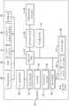
图2是根据实施例的示例性的基于导管的手术系统的示意性框图。2 is a schematic block diagram of an exemplary catheter-based surgical system, according to an embodiment.
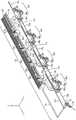
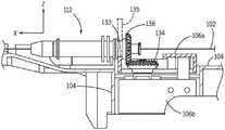
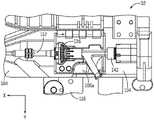
图3是根据实施例的基于导管的手术系统的示例性床边系统的等距视图。3 is an isometric view of an exemplary bedside system of a catheter-based surgical system, according to an embodiment.
图4A是具有负载感测系统的装置模块的示意性端视图,该负载感测系统包括隔离部件和负载感测部件。4A is a schematic end view of a device module having a load sensing system including isolation components and load sensing components.
图4B是图4A的另一实施例的示意性端视图,该实施例包括致动器来旋转和/或夹紧/松开位于负载感测部件外部的EMD。4B is a schematic end view of another embodiment of FIG. 4A including an actuator to rotate and/or clamp/unclamp an EMD located external to the load sensing component.
图4C是图4A的另一实施例的示意性端视图,该实施例包括在至少一个偏轴(未测量)方向上的负载感测部件的轴承支撑件。4C is a schematic end view of another embodiment of FIG. 4A including a bearing support for the load sensing component in at least one off-axis (not measured) direction.
图4D是图4A的另一实施例的示意性端视图,该实施例包括旋转和/或夹紧/松开位于负载感测部件外部的EMD的致动器和在至少一个偏轴(未测量)方向上的负载感测部件的轴承支撑件。FIG. 4D is a schematic end view of another embodiment of FIG. 4A including an actuator that rotates and/or clamps/unclamps an EMD located outside the load sensing component and at least one off-axis (not measured) ) in the direction of the load-sensing component bearing support.
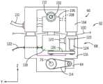
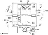
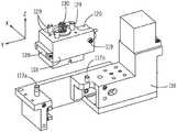
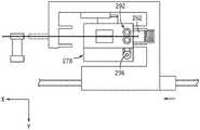
图5A是具有负载感测系统的驱动模块的俯视图,所述驱动模块包括旋转和/或夹紧/松开位于负载感测部件外部的EMD的致动器以及在至少一个偏轴(未测量)方向上的负载感测部件的轴承支撑件。5A is a top view of a drive module with a load sensing system including an actuator that rotates and/or clamps/unclamps an EMD located external to the load sensing component and at least one off-axis (not measured) Bearing supports for load sensing components in the direction.
图5B是具有负载感测系统的驱动模块的侧视图,所述驱动模块包括旋转和/或夹紧/松开位于负载感测部件外部的EMD的致动器以及在至少一个偏轴(未测量)方向上的负载感测部件的轴承支撑件。5B is a side view of a drive module with a load sensing system that includes an actuator that rotates and/or clamps/unclamps an EMD located external to the load sensing component and that is at least one off-axis (not measured) ) in the direction of the load-sensing component bearing support.
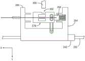
图5C是包括负载感测部件和驱动模块基部部件的驱动模块的等距视图。5C is an isometric view of a drive module including a load sensing component and a drive module base component.
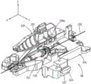
图5D是根据实施例的具有负载感测系统的装置模块和能够接收具有EMD的装置上适配器的盒的分解等距视图。5D is an exploded isometric view of a device module with a load sensing system and a cassette capable of receiving an on-device adapter with an EMD, according to an embodiment.
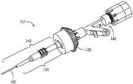
图5E是根据实施例的具有EMD装置上适配器的导管的等距视图。5E is an isometric view of a catheter with an adapter on an EMD device, according to an embodiment.
图5F是根据实施例的具有EMD装置上适配器的导丝的等距视图。5F is an isometric view of a guidewire with an adapter on an EMD device, according to an embodiment.
图5G是具有驱动模块基部部件和负载感测部件的驱动模块的分解等距视图。5G is an exploded isometric view of a drive module with a drive module base component and a load sensing component.
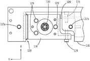
图5H是图5A的特写俯视图,其示出了被连接到驱动模块基部部件内的负载传感器的负载感测部件。5H is a close-up top view of FIG. 5A showing the load sensing component connected to the load sensor within the drive module base component.
图5I是根据实施例的具有带EMD的装置上适配器的盒的等距视图。5I is an isometric view of a cartridge with an on-device adapter with an EMD, according to an embodiment.
图5J是盒的分解等距视图,其示出了隔离部件的第一部件和第二部件。Figure 5J is an exploded isometric view of the cartridge showing the first and second parts of the isolation member.
图5K是盒的底侧及其与驱动模块的连接的分解等距视图。5K is an exploded isometric view of the bottom side of the cartridge and its connection to the drive module.
图5L是图5I的部分侧视图,其示出了作为盒的一部分具有被支撑在隔离部件内的EMD的装置上适配器。5L is a partial side view of FIG. 5I showing an on-device adapter as part of a cassette with an EMD supported within an isolation member.
图5M是图5I的端部横截面图,其示出了盒中的锥齿轮的啮合。Figure 5M is an end cross-sectional view of Figure 5I showing the meshing of bevel gears in the cassette.
图6A是根据实施例的盒的俯视图,其具有隔离部件和盒壳体。Figure 6A is a top view of a cartridge with a spacer member and a cartridge housing, according to an embodiment.
图6B是根据实施例的隔离部件和盒的端部横截面图。6B is an end cross-sectional view of a spacer member and cassette according to an embodiment.
图6C是根据实施例的隔离部件和盒壳体的仰视图。6C is a bottom view of the spacer member and cartridge housing according to an embodiment.
图7是图4D的负载感测系统的示例性实施例的示意性端部横截面图,其指示出了一次性盒部件和主要驱动模块部件(capital drive module component)。7 is a schematic end cross-sectional view of the exemplary embodiment of the load sensing system of FIG. 4D, indicating the disposable cartridge component and the capital drive module component.
图8是负载感测系统的示意性俯视图,所述负载感测系统包括双锥齿轮驱动机构。8 is a schematic top view of a load sensing system including a double bevel gear drive mechanism.
图9A是图8的负载感测系统的示例性实施例的示意性侧视图,其针对由双锥驱动器致动的筒夹机构,且在致动器绞盘处具有转矩传感器。9A is a schematic side view of an exemplary embodiment of the load sensing system of FIG. 8 for a collet mechanism actuated by a double cone drive with a torque sensor at the actuator capstan.
图9B是图9A的负载感测系统的另一实施例的示意性侧视图。Figure 9B is a schematic side view of another embodiment of the load sensing system of Figure 9A.
图9C是图9B的负载感测系统的的示意性等距视图。Figure 9C is a schematic isometric view of the load sensing system of Figure 9B.
图9D是具有单个转矩传感器的筒夹机构的负载感测系统的示例性实施例的示意性侧视图。9D is a schematic side view of an exemplary embodiment of a load sensing system of a collet mechanism with a single torque sensor.
图9E是负载感测系统的针对具有单个转矩传感器的毂驱动机构的示例性实施例的示意性侧视图。9E is a schematic side view of an exemplary embodiment of a load sensing system for a hub drive mechanism with a single torque sensor.
图9F是用于测量EMD上的力和转矩的图9B的负载感测系统的另一实施例的示意性侧视图。9F is a schematic side view of another embodiment of the load sensing system of FIG. 9B for measuring forces and torques on an EMD.
图10A是用于测量EMD上的力和转矩的负载感测系统的另一实施例的示意性侧视图。10A is a schematic side view of another embodiment of a load sensing system for measuring force and torque on an EMD.
图10B是用于测量EMD上的力和转矩的负载感测系统的另一实施例的示意性俯视图。10B is a schematic top view of another embodiment of a load sensing system for measuring force and torque on an EMD.
图11是使用在第一装置上适配器远侧的轮胎驱动器测量具有重置运动的机器人系统中的EMD上的力和转矩的负载感测系统的实施例的示意性俯视图。11 is a schematic top view of an embodiment of a load sensing system for measuring forces and torques on an EMD in a robotic system with reset motion using a tire driver distal to the adapter on the first device.
图12A是使用在第一装置上适配器近侧的轮胎驱动器测量具有重置运动的机器人系统中的EMD上的力和转矩的负载感测系统的实施例的示意性俯视图。12A is a schematic top view of an embodiment of a load sensing system for measuring forces and torques on an EMD in a robotic system with reset motion using a tire driver proximal to an adapter on a first device.
图12B是图12A的负载感测系统的示例性实施例的示意性侧视图。Figure 12B is a schematic side view of the exemplary embodiment of the load sensing system of Figure 12A.
图13A是测量具有传感器的自动校准和过载保护的机器人系统中的EMD上的力和转矩的负载感测系统的实施例的示意性俯视图,所述负载感测系统被示为处于中性(没有负载)位置。13A is a schematic top view of an embodiment of a load sensing system that measures forces and torques on an EMD in a robotic system with automatic calibration of sensors and overload protection, the load sensing system shown in neutral ( no load) position.
图13B是图13A的负载感测系统的实施例的示意性俯视图,所述负载感测系统被示为处于加载位置。13B is a schematic top view of the embodiment of the load sensing system of FIG. 13A shown in a loaded position.
图14A是测量具有传感器的自动校准和过载保护的机器人系统中的EMD上的力和转矩的负载感测系统的另一实施例的示意性俯视图,所述负载感测系统被示为处于中性(没有负载)位置。14A is a schematic top view of another embodiment of a load sensing system that measures forces and torques on an EMD in a robotic system with automatic calibration of sensors and overload protection, the load sensing system shown in the middle Sexual (no load) position.
图14B是图14A的负载感测系统的实施例的示意性俯视图,所述负载感测系统被示为处于加载位置。14B is a schematic top view of an embodiment of the load sensing system of FIG. 14A shown in a loaded position.
图15A是测量具有传感器的自动校准和过载保护的机器人系统中的EMD上的力和转矩的负载感测系统的另一实施例的示意性俯视图,所述负载感测系统被示为处于中性(没有负载)位置,其中驱动致动器位于负载感测部件内部。15A is a schematic top view of another embodiment of a load sensing system that measures forces and torques on an EMD in a robotic system with automatic calibration of sensors and overload protection, the load sensing system being shown in the middle The free (unloaded) position, where the drive actuator is located inside the load-sensing component.
图15B是图15A的负载感测系统的实施例的示意性俯视图,所述负载感测系统被示为处于加载位置,其中驱动致动器位于负载感测部件内部。15B is a schematic top view of an embodiment of the load sensing system of FIG. 15A shown in a loaded position with the drive actuator located inside the load sensing component.
图16A是测量具有传感器的自动校准和过载保护的机器人系统中的EMD上的力和转矩的负载感测系统的另一实施例的示意性俯视图,所述负载感测系统被示为处于中性(没有负载)位置。16A is a schematic top view of another embodiment of a load sensing system that measures forces and torques on an EMD in a robotic system with automatic calibration of sensors and overload protection, the load sensing system shown in the middle Sexual (no load) position.
图16B是测量具有传感器的自动校准和过载保护的机器人系统中的EMD上的力和转矩的负载感测系统的另一实施例的示意性俯视图,所述负载感测系统被示为处于加载位置。16B is a schematic top view of another embodiment of a load sensing system that measures forces and torques on an EMD in a robotic system with automatic calibration of sensors and overload protection, the load sensing system shown under load Location.
图17是具有两个输入(感测负载和寄生负载)和一个输出(实际负载)的处理器的框图。Figure 17 is a block diagram of a processor with two inputs (sense load and parasitic load) and one output (actual load).
图18是指示出被组合成寄生负载的负载的总和符号的框图。FIG. 18 is a block diagram indicating the summed symbols of loads combined into parasitic loads.
具体实施方式Detailed ways
图1是根据实施例的示例性基于导管的手术系统10的透视图。基于导管的手术系统10可以被用于执行基于导管的医疗手术,例如经皮介入手术,诸如经皮冠状动脉介入(PCI)(例如,治疗STEMI)、神经血管介入手术(NVI)(例如,治疗紧急大血管闭塞(ELVO))、外周血管介入手术(PVI)(例如,用于严重肢体缺血(CLI)等)。基于导管的医疗手术可以包括诊断导管插入手术,其间一个或更多个导管或者其他细长医疗装置(EMD)被用于辅助病人疾病的诊断。例如,在基于导管的诊断手术的一种实施例期间,造影剂通过导管被注射到一个或更多个动脉上并且获取病人血管系统的图像。基于导管的医疗手术还可包括基于导管的治疗手术(例如,血管成形术、支架置入、外周血管疾病的治疗、凝块清除、动静脉畸形治疗、动脉瘤治疗等),在此期间使用导管(或其他EMD)治疗疾病。可以通过包括附属装置54(如图2所示)来改善治疗手术,该附属装置例如是血管内超声(IVUS)、光学相干断层扫描(OCT)、血流储备分数(FFR)等。然而,应当注意,本领域技术人员应该认识到,可以基于要执行的手术类型来选择某些特定的经皮介入装置或部件(例如,导丝类型、导管类型等)。基于导管的手术系统10能够执行任意数量的基于导管的医疗手术,且只需稍加调整就能适应手术中要使用的特定经皮介入装置。FIG. 1 is a perspective view of an exemplary catheter-based
基于导管的手术系统10包括床边单元20和控制站26以及其他元件。床边单元20包括邻近病人12放置的机器人驱动器24和定位系统22。病人12支撑在病床18上。定位系统22被用于定位并支撑机器人驱动器24。定位系统22可以例如是机器人臂、铰接臂、保持器等等。定位系统22可以在一端处被附接到例如病床18上的轨、基部或者推车。定位系统22的另一端被附接到机器人驱动器24。定位系统22可以(与机器人驱动器24一起)被移走以允许病人12被放置在病床18上。一旦病人12被定位在病床18上,则定位系统22可以被用于针对手术相对于病人12安置或定位机器人驱动器24。在实施例中,病床18被底座17可操作地支撑,该底座17被固定到地板和/或地面。病床18能够相对于底座17以多个自由度移动,例如滚动、俯仰和偏航。床边单元20也可以包括控件和显示器46(在图2中示出)。例如,控件和显示器可以位于机器人驱动器24的壳体上。The catheter-based
大体而言,机器人驱动器24可以配备有适当的经皮介入装置和附件48(在图2中示出)(例如,导丝、各种类型的导管,包括球囊导管、支架输送系统、支架回收器、栓塞线圈、液体栓塞、抽吸泵、输送造影剂的装置、药物、止血阀适配器、注射器、旋塞、充气装置等),以允许用户或操作者11通过操作各种控件(诸如位于控制站26的控件和输入)经由机器人系统执行基于导管的医疗手术。床边单元20且具体地机器人驱动器24可以包括任意数量的部件和/或部件组合以提供具有如本文所述的功能的床边单元20。在控制站26处的用户或操作者11被称为控制站用户或控制站操作者并且在本文被称为用户或操作者。在床边单元20处的用户或操作者被称为床边单元用户或床边单元操作者。机器人驱动器24包括被安装在轨或线性构件60(在图3中示出)上的多个装置模块32a-d。轨或线性构件60引导并支撑装置模块。每个装置模块32a-d均可以被用于驱动EMD,诸如导管或导丝。例如,机器人驱动器24可以被用于将导丝自动地馈送到在病人12的动脉中的诊断导管中和引导导管中。一个或更多个装置(诸如EMD)经由例如引导器鞘在插入点16处进入病人12的身体(例如,血管)。In general, the
床边单元20与控制站26通信,从而允许通过控制站26的用户输入生成的信号被无线地或经由硬线被传输到床边单元20以控制床边单元20的各种功能。如下文讨论的,控制站26可以包括控制计算系统34(在图2中示出)或者通过控制计算系统34被联接到床边单元20。床边单元20也可以提供反馈信号(例如,负载、速度、操作条件、警告信号、错误代码等等)至控制站26、控制计算系统34(在图2中示出)或者两者。可以经由通信链路提供在控制计算系统34与基于导管的手术系统10的各个部件之间的通信,该通信链路可以是无线连接、线缆连接或者能够允许部件之间进行通信的任意其他手段。控制站26或其他类似控制系统可以位于本地地点(例如,图2所示的本地控制站38)或者在远程地点(例如,图2中所示的远程控制站和计算机系统42)。导管手术系统10可以通过位于本地地点的控制站、位于远程地点的控制站或者同时由本地控制站和远程控制站二者来操作。在本地地点,用户或操作者11和控制站26位于与病人12和床边单元20相同房间中或相邻房间中。如本文所用的,本地地点是床边单元20和病人12或受试者(例如,动物或尸体)的位置,并且远程地点是被用于远程地控制床边单元20的用户或操作者11和控制站26的位置。在远程地点的控制站26(和控制计算系统)和在本地地点的床边单元20和/或控制计算系统可以通过使用通信系统和服务36(在图2中示出)、例如通过因特网进行通信。在实施例中,远程地点和本地(病人)地点彼此远离,例如在同一建筑物中的不同房间中、同一城市中的不同建筑物中、不同城市中或者远程地点不需要物理访问在本地地点处的床边单元20和/或病人12的其他不同位置。The
控制站26大体包括一个或更多个输入模块28,其被构造成接收用户输入来操作基于导管的手术系统10的各种部件或者系统。在所示实施例中,控制站26允许用户或操作者11控制床边单元20来执行基于导管的医疗手术。例如,输入模块28可以被构造成导致床边单元20通过使用与机器人驱动器24接口连接的经皮介入装置(例如EMD)来执行各种任务(例如推进、缩回或者旋转导丝;推进、缩回或者旋转导管;充气或放气位于导管上的球囊;定位和/或部署支架;定位和/或部署支架回收器;定位和/或部署线圈;将造影剂注射到导管中;将液体栓塞注入到导管中;将药物或生理盐水注入到导管中;在导管上进行抽吸;或执行任何其他可能作为基于导管的医疗手术的一部分被执行的功能)。机器人驱动器24包括各种驱动机构以导致包括经皮介入装置的床边单元20的部件的运动(例如,轴向和旋转运动)。Control station 26 generally includes one or
在一种实施例中,输入模块28可以包括一个或更多个触摸屏、操纵杆、滚轮和/或按钮。除了输入模块28之外,控制站26还可以使用附加的用户控件44(在图2中示出),诸如脚部开关和用于声音命令的麦克风等等。输入模块28可以被构造成推进、缩回或旋转各种部件和经皮介入装置,诸如导丝和一个或更多个导管或微导管。按钮可以例如包括紧急停止按钮、倍增器按钮、装置选择按钮和自动移动按钮。当推动紧急停止按钮时,断开或移除至床边单元20的功率(例如,电功率)。当处于速度控制模式中时,倍增器按钮用于增加或减少相关联的部件响应于输入模块28的操纵移动的速度。当处于位置控制模式中时,倍增器按钮改变在输入距离和输出命令距离之间的映射。装置选择按钮允许用户或操作者11选择输入模块28控制被装载到机器人驱动器24中的哪个经皮介入装置。自动移动按钮被用于使得能够进行算法运动,该基于导管的手术系统10可以在经皮介入装置上执行该算法运动而不需要来自用户或操作者11的直接命令。在一种实施例中,输入模块28可以包括显示在触摸屏(其可以是或者可以不是显示器30的一部分)上的一个或更多个控件或图标(未示出),当被激活时,所述控件或图标导致基于导管的手术系统10的部件的操作。输入模块28也可以包括球囊或支架控件,其被构造成充气或放气球囊和/或部署支架。每个输入模块28均可以包括一个或更多个按钮、滚轮、操纵杆、触摸屏等等,其可以被用于控制该控件专用的一个或更多个具体部件。此外,一个或更多个触摸屏可以显示与输入模块28的各部分或者基于导管的手术系统10的各部件相关的一个或更多个图标(未示出)。In one embodiment, the
控制站26可以包括显示器30。在另一些实施例中,控制站26可以包括两个或更多个显示器30。显示器30可以被构造成向位于控制站26处的用户或操作者11显示信息或病人特有的数据。例如,显示器30可以被构造成显示图像数据(例如,X射线图像、MRI图像、CT图像、超声图像等等)、血液动力学数据(例如,血压、心率等等)、病人记录信息(例如,医疗历史、年龄、重量等等)、病变或治疗评估数据(例如,IVUS、OCT、FFR等等)。此外,显示器30可以被构造成显示手术专有信息(例如,例如,手术检查表、建议、手术持续时间、导管或导丝位置、输送的药物或造影剂的体积等)。此外,显示器30可以被构造成显示信息以提供与控制计算系统34(在图2中示出)相关联的功能。显示器30可以包括触摸屏能力以便提供系统的某些用户输入能力。Control station 26 may include display 30 . In other embodiments, the control station 26 may include two or more displays 30 . Display 30 may be configured to display information or patient-specific data to user or
基于导管的手术系统10也包括成像系统14。成像系统14可以是可以与基于导管的医疗手术结合使用的任意医疗成像系统(例如非数字X射线、数字X射线、CT、MRI、超声波等等)。在示例性实施例中,成像系统14是与控制站26通信的数字X射线成像装置。在一种实施例中,成像系统14可以包括C形臂(在图1中示出),其允许成像系统14部分地或完全地在病人12周围旋转以便获得相对于病人12处于不同角度位置的图像(例如,矢状面视图、尾侧视图、前后视图等等)。在一种实施例中,成像系统14是包括C形臂的荧光系统,其具有X射线源13和探测器15,也被称为图像增强器。The catheter-based
成像系统14可以被构造成在手术期间获取病人12的适当区域的X射线图像。例如,成像系统14可以被构造成获取头部的一个或更多个X射线图像以便诊断神经血管状况。成像系统14也可以被构造成在基于导管的医疗手术期间获取一个或更多个X射线图像(例如,实时图像)以便辅助控制站26的用户或操作者11在手术期间适当地定位导丝、引导导管、微导管、支架回收器、线圈、支架、球囊等等。一个或更多个图像可以被显示在显示器30上。例如,图像可以被显示在显示器30上以允许用户或操作者11将引导导管或导丝准确地移动到适当位置。
为了明确方向,引入具有X、Y和Z轴线的矩形坐标系。正X轴线沿着纵向(轴向)远侧方向取向,即沿着从近端到远端的方向,换言之从近侧到远侧的方向。Y和Z轴线处于横于X轴线的平面内,且正Z轴线指向上,即与重力相反的方向,并且Y轴线由右手规则自动确定。To clarify the orientation, a rectangular coordinate system with X, Y and Z axes is introduced. The positive X-axis is oriented in the longitudinal (axial) distal direction, ie in the direction from proximal to distal, in other words proximal to distal. The Y and Z axes lie in a plane transverse to the X axis, with the positive Z axis pointing upward, ie opposite gravity, and the Y axis is automatically determined by the right-hand rule.
图2是根据示例性实施例的基于导管的手术系统10的框图。导管-手术系统10可以包括控制计算系统34。控制计算系统34可以物理上是例如控制站26(在图1中示出)的一部分。控制计算系统34可以大体是适于给基于导管的手术系统10提供本文描述的各种功能的电子控制单元。例如,控制计算系统34可以是嵌入系统、专用电路、被编程为具有本文所描述的功能的通用系统等等。控制计算系统34与床边单元20、通信系统和服务36(例如,因特网、防火墙、云服务、会话管理器、医院网络等等)、本地控制站38、附加通信系统40(例如,远程呈现系统)、远程控制站和计算系统42和病人传感器56(例如,心电图(ECG)装置、脑电图(EEG)装置、血压监测器、温度监测器、心率监测器、呼吸监测器等等)通信。控制计算系统也与成像系统14、病床18、附加医疗系统50、造影剂注射系统52和附属装置54(例如,IVUS、OCT、FFR等等)通信。床边单元20包括机器人驱动器24、定位系统22并且可以包括附加控件和显示器46。如上所述,附加控件和显示器可以位于机器人驱动器24的壳体上。介入装置和附件48(例如,导线、导管等)与床边系统20接口连接。在实施例中,介入装置和附件48可以包括专用装置(例如,IVUS导管、OCT导管、FFR线、用于造影剂的诊断导管等等),其接口连接到它们相应的附属装置54,即IVUS系统、OCT系统和FFR系统等等。FIG. 2 is a block diagram of a catheter-based
在各种实施例中,控制计算系统34被构造成基于用户与(例如,控制站26(在图1中示出)的、诸如本地控制站38或者远程控制站42的)输入模块28的交互和/或基于控制计算系统34可获得的信息来产生控制信号,以致可以通过使用基于导管的手术系统10来执行医疗手术。本地控制站38包括一个或更多个显示器30、一个或更多个输入模块28和附加用户控件44。远程控制站和计算系统42可以包括与本地控制站38类似的部件。远程42和本地38控制站能够基于其所需功能是不同的并且是定制的。附加用户控件44可以例如包括一个或更多个脚部输入控件。脚部输入控件可以被构造成允许用户选择成像系统14的功能,诸如开启和关断X射线以及滚动通过不同的存储图像。在另一实施例中,脚部输入装置可以被构造成允许用户选择哪个装置被映射到被包括在输入模块28中的滚轮。附加通信系统40(例如,音频会议、视频会议、远程呈现等)可以被用于帮助操作者与病人、医务人员(例如,血管造影人员)和/或床边附近的设备进行交互。In various embodiments,
基于导管的手术系统10可以被连接到或被构造成包括没有被明确示出的任何其他系统和/或装置。例如,基于导管的手术系统10可以包括图像处理引擎、数据存储和归档系统、自动球囊和/或支架充气系统、医学注射系统、医学跟踪和/或记录系统、用户记录、加密系统、限制访问或使用基于导管的手术系统10的系统等等。The catheter-based
如所述,控制计算系统34与包括机器人驱动器24、定位系统22且可以包括附加控件和显示器46的床边单元20通信,并且可以提供控制信号至床边单元20以控制被用于驱动经皮介入装置(例如,导丝、导管等等)的马达和驱动机构的操作。可以作为机器人驱动器24的一部分来提供各种驱动机构。图3是根据实施例的用于基于导管的手术系统10的机器人驱动器的等距视图。在图3中,机器人驱动器24包括被联接到线性构件60的多个装置模块32a-d。每个装置模块32a-d经由被可动地安装到线性构件60的台62a-d被联接到线性构件60。装置模块32a-d可以通过使用诸如偏移支架78a-d的连接器被连接到台62a-d。在另一实施例中,装置模块32a-d被直接安装到台62a-d。每个台62a-d可以被独立地致动成沿着线性构件60线性移动。因此,每个台62a-d(和被联接到台62a-d的对应装置模块32a-d)可以相对彼此和相对于线性构件60独立运动。驱动机构被用于致动每个台62a-d。在图3中所示的实施例中,驱动机构包括被联接到每个台62a-d和台驱动机构76的独立的台平移马达64a-d,例如,经由旋转螺母的丝杠、经由小齿轮的齿条、经由小齿轮或带轮的带、经由链轮的链条,或者台平移马达64a-d本身可以是线性马达。在一些实施例中,台驱动机构76可以是这些机构的组合,例如,每个台62a-d可以使用不同类型的台驱动机构。在台驱动机构是丝杠和旋转螺母的实施例中,丝杠可以旋转并且每个台62a-d可以接合丝杠和与丝杠脱离以移动,例如前进或缩回。在图3中所示的实施例中,台62a-d和装置模块32a-d处于串联驱动构造。As described, the
每个装置模块32a-d包括驱动模块68a-d和被安装在驱动模块68a-d上且与其联接的盒66a-d。在图3中所示的实施例中,每个盒66a-d以竖直取向被安装到驱动模块68a-d。在另一些实施例中,每个盒66a-d可以以其他安装取向被安装到驱动模块68a-d。每个盒66a-d被构造成与EMD(未示出)的近侧部分接口连接并支撑该近侧部分。此外,每个盒66a-d可以包括除了通过对应台62a-d的致动提供的沿着线性构件60线性移动的线性运动之外还提供一个或更多个自由度的元件。例如,盒66a-d可以包括可以在盒被联接到驱动模块68a-d时被用于旋转EMD的元件。每个驱动模块68a-d包括至少一个联接器以便提供至每个盒66a-d中的机构的驱动接口以便提供附加自由度。每个盒66a-d也包括其内定位有装置支撑件79a-d的通道,并且每个装置支撑件79a-d被用于防止EMD屈曲。支撑臂77a、77b和77c分别被附接到每个装置模块32a、32b和32c,以便分别为装置支撑件79b、79c和79d的近端提供固定支撑点。机器人驱动器24也可以包括被连接到装置支撑件79、远侧支撑臂70和支撑臂77o的装置支撑连接部72。支撑臂77o被用于为被装纳在最远侧装置模块32a中的最远侧装置支撑件79a的近端提供固定支撑点。此外,引导器接口支撑件(重定向器)74可以被连接到装置支撑连接部72和EMD(例如,引导器鞘)。机器人驱动器24的构造通过使用在单个线性构件上的致动器具有减小驱动机器人驱动器24的体积和重量的优点。Each
为了防止病原体污染病人,医护人员在容纳床边单元20和病人12或受试者(在图1中示出)的房间内使用无菌技术。容纳床边单元20和病人12的房间可以例如是导管室或血管造影室。无菌技术包括包括使用无菌屏障、无菌设备、适当的病人准备、环境控制和接触指南。因此,所有的EMD和介入附件均被消毒并且仅能够接触无菌屏障或者无菌设备。在实施例中,无菌布帘(未示出)被放置在非无菌的机器人驱动器24上。每个盒66a-d被消毒并且用作在被遮盖机器人驱动器24和至少一个EMD之间的无菌接口。每个盒66a-d能够被设计成针对单次使用被消毒,或者整体或部分被重复消毒,以致盒66a-d或其部件能够在多次手术中使用。To prevent pathogens from contaminating the patient, medical personnel use aseptic technique in the room that houses the
定义和术语Definitions and Terminology
EMD:术语细长医疗装置(EMD)指的是、但不限于:导管(例如,引导导管、微导管、球囊/支架导管)、基于丝的装置(例如,导丝、栓塞线圈、支架回收器等等)以及包括其任意组合的医疗装置。EMD: The term elongated medical device (EMD) refers to, but is not limited to, catheters (eg, guide catheters, microcatheters, balloon/stent catheters), wire-based devices (eg, guidewires, embolic coils, stent retrievals) devices, etc.) and medical devices including any combination thereof.
负载:术语负载指的是力、转矩或者力和转矩的组合。负载可以包括力的单个分量(沿着单个轴线的力)或者力的多个分量(多轴力)和/或转矩的单个分量(绕单个轴线的转矩)或转矩的多个分量(多轴转矩)。负载可以是静态的(不随时间变化)或者动态的(随时间变化)。Load: The term load refers to force, torque, or a combination of force and torque. Loads can include a single component of force (force along a single axis) or multiple components of force (multiaxial force) and/or a single component of torque (torque about a single axis) or multiple components of torque ( multi-axis torque). Loads can be static (time-invariant) or dynamic (time-varying).
力:术语力指的是导致或试图导致物体运动的因素。作用在物体上的力可以改变物体的运动、阻止物体的运动、平衡已经作用在物体上的力以及导致物体中的内部应力。力的特征包括力的幅值、力的作用线(力作用所沿的轴线)、力的方向(对应于压力或拉伸力)和力的作用点。Force: The term force refers to what causes or attempts to cause an object to move. Forces acting on an object can alter the object's motion, prevent the object's motion, balance forces already acting on the object, and cause internal stresses in the object. The characteristics of a force include the magnitude of the force, the line of action of the force (the axis along which the force acts), the direction of the force (corresponding to a compressive or tensile force), and the point of application of the force.
转矩:术语转矩指的是导致或试图导致物理物体的旋转运动的因素。作用在物体上的转矩可以改变物体的旋转运动、阻止物体的旋转运动、平衡已经作用在物体上的转矩以及导致物体中的内部应力。转矩的特征包括转矩的幅值、转矩的作用线、转矩的方向(绕作用线是顺时针或逆时针)和转矩的作用点。术语转矩也指力矩、力的力矩、旋转力、扭力和“转动效果”。转矩是力的旋转当量。转矩的幅值也能够被确定为力的幅值与力的作用线与旋转轴线的垂直距离的乘积。Torque: The term torque refers to the factor that causes or attempts to cause rotational motion of a physical object. The torque acting on an object can change the rotational motion of the object, prevent the rotational motion of the object, balance the torque already acting on the object, and cause internal stresses in the object. The characteristics of the torque include the magnitude of the torque, the line of action of the torque, the direction of the torque (clockwise or counterclockwise around the line of action), and the point of action of the torque. The term torque also refers to moment, moment of force, rotational force, torsional force and "turning effect". Torque is the rotational equivalent of force. The magnitude of the torque can also be determined as the product of the magnitude of the force and the vertical distance of the line of action of the force from the axis of rotation.
控制计算系统:术语控制计算系统包括具有处理电路的处理器。处理器包括中央处理器、专用处理器(ASIC)、包含一个或更多个处理部件的电路、分布式处理部件组、被构造成处理的分布式计算机组等,其被构造成提供本文讨论的模块或子系统部件的功能。存储器单元(例如,存储器装置、存储装置等等)是用于存储数据和/或计算机代码以用于完成和/或有助于本公开描述的各种过程的装置。存储器单元可以包括易失性存储器和/或非易失性存储器。存储器单元可以包括数据库部件、目标代码部件、脚本部件和/或用于支持本公开中描述的各种活动的任何其他类型的信息结构。根据示例性实施例,过去、现在或未来的任何分布式和/或本地存储器装置可以与本公开的系统和方法一起使用。根据示例性实施例,存储器单元被通信地连接到一个或更多个相关联的处理电路。这个连接可以是经由电路或任何其他有线、无线或网络连接,并且包括用于执行本文所描述的一个或更多个过程的计算机代码。单个存储器单元可以包括各种单独的存储器装置、芯片、磁盘和/或其他存储结构或系统。模块或子系统部件可以是用于执行每个模块的相应功能的计算机代码(例如,目标代码、程序代码、编译代码、脚本代码、可执行代码或其任意组合)。Control computing system: The term control computing system includes a processor with processing circuitry. A processor includes a central processing unit, an application specific processor (ASIC), a circuit containing one or more processing elements, a group of distributed processing elements, a group of distributed computers structured to process, etc., which are structured to provide the The function of a block or subsystem component. A memory unit (eg, memory device, storage device, etc.) is a device used to store data and/or computer code for accomplishing and/or facilitating the various processes described in this disclosure. The memory cells may include volatile memory and/or non-volatile memory. The memory unit may include database components, object code components, script components, and/or any other type of information structure for supporting the various activities described in this disclosure. According to exemplary embodiments, any distributed and/or local memory device past, present or future may be used with the systems and methods of the present disclosure. According to an exemplary embodiment, the memory unit is communicatively connected to one or more associated processing circuits. This connection may be via a circuit or any other wired, wireless or network connection and includes computer code for performing one or more of the processes described herein. A single memory unit may include various individual memory devices, chips, magnetic disks, and/or other storage structures or systems. A module or subsystem component may be computer code (eg, object code, program code, compiled code, script code, executable code, or any combination thereof) for performing the respective functions of each module.
远侧和近侧:术语远侧和近侧限定两个不同特征的相对位置。关于机器人驱动器,术语远侧和近侧由机器人驱动器在其预期用途中相对于病人的位置被定义。Distal and Proximal: The terms distal and proximal define the relative positions of two different features. With regard to the robotic drive, the terms distal and proximal are defined by the position of the robotic drive relative to the patient in its intended use.
当被用于定义相对位置时,远侧特征是在机器人驱动器处于其预期使用位置时机器人驱动器的比近侧特征更靠近病人的特征。在病人体内,沿着路径更远离进入点的任何血管标记被认为比更靠近进入点的标记在更远侧,其中进入点是EMD进入病人的点。类似地,近侧特征是在机器人驱动器处于其预期使用位置时比远侧特征更远离病人的特征。When used to define relative positions, distal features are features of the robotic drive that are closer to the patient than proximal features when the robotic drive is in its intended use position. In the patient, any vessel markers along the path that are further away from the point of entry, which is the point at which the EMD enters the patient, are considered more distal than markers that are closer to the point of entry. Similarly, proximal features are features that are farther from the patient than distal features when the robotic drive is in its intended use position.
当被用于定义方向时,远侧方向指的是在机器人驱动器处于其预期使用位置时,某物正在移动或旨在移动的路径,或某物从近侧特征指向或朝向远侧特征和/或患者所沿的路径。近侧方向是与远侧方向相对的方向。参考图1,从面向病人的操作者的角度示出机器人装置。在这种布置中,远侧方向是沿着正X坐标轴线并且近侧方向是沿着负X坐标轴线。参考图3,EMD在远侧方向上在通过限定机器人驱动器24的远端的引导器接口支撑件74朝向病人的路径上移动。机器人驱动器24的近端是沿着负X轴线最远离远端的点。When used to define a direction, the distal direction refers to the path that something is moving or is intended to move when the robotic drive is in its intended position of use, or the path that something is pointing from a proximal feature or towards a distal feature and/or or the path the patient follows. The proximal direction is the opposite direction to the distal direction. Referring to Figure 1, the robotic device is shown from the perspective of a patient facing operator. In this arrangement, the distal direction is along the positive X coordinate axis and the proximal direction is along the negative X coordinate axis. Referring to FIG. 3 , the EMD is moved in the distal direction on a path toward the patient through the
纵轴线:术语构件(例如,EMD或在基于导管的手术系统中的其他元件)的纵轴线是沿着该构件的长度的线或轴线,其在从构件的近侧部分到构件的远侧部分的方向上穿过构件横截面的中心。例如,导丝的纵轴线是在从导丝的近侧部分到导丝的远侧部分的方向上的中央轴线,不过导丝可以在相关部分上可以是非线性的。Longitudinal axis: The term longitudinal axis of a member (eg, EMD or other element in a catheter-based surgical system) is the line or axis along the length of the member that extends from the proximal portion of the member to the distal portion of the member through the center of the cross-section of the member. For example, the longitudinal axis of the guidewire is the central axis in the direction from the proximal portion of the guidewire to the distal portion of the guidewire, although the guidewire may be non-linear in the relevant portion.
轴向和旋转运动:术语构件的轴向运动指的是构件沿着构件的纵轴线的平移。当EMD的远端沿着其纵轴线在远侧方向上轴向移动到病人体内或进一步移动到病人体内时,EMD正被推进。当EMD的远端沿着其纵轴线在近侧方向上轴向移出病人身体或进一步移出病人身体时,EMD正被撤回。术语构件的旋转运动指的是构件绕构件的局部纵轴线的角度取向的变化。EMD的旋转运动对应于由于施加的转矩导致的EMD绕其纵轴线的顺时针或逆时针旋转。Axial and rotational movement: The term axial movement of a member refers to translation of the member along the longitudinal axis of the member. The EMD is being advanced as the distal end of the EMD moves axially into the patient or further into the patient in a distal direction along its longitudinal axis. The EMD is being withdrawn when the distal end of the EMD is moved axially or further out of the patient's body in a proximal direction along its longitudinal axis. The term rotational movement of a member refers to a change in the angular orientation of the member about the local longitudinal axis of the member. The rotational motion of the EMD corresponds to a clockwise or counterclockwise rotation of the EMD about its longitudinal axis due to an applied torque.
轴向和侧向插入:术语轴向插入指的是沿着第二构件的纵轴线将第一构件插入到第二构件中。术语侧向插入指的是沿着在与第二构件的纵轴线垂直的平面中的方向将第一构件插入到第二构件中。这也能够被称为径向加载或侧向加装。Axial and lateral insertion: The term axial insertion refers to the insertion of a first member into a second member along the longitudinal axis of the second member. The term lateral insertion refers to the insertion of the first member into the second member along a direction in a plane perpendicular to the longitudinal axis of the second member. This can also be referred to as radial loading or side loading.
夹紧/松开(Pinch/Unpinch):术语夹紧指的是将EMD可释放地固定到构件,以致当构件移动时,EMD和构件一起移动。术语松开指的是从构件释放EMD,以致当构件移动时,EMD和构件独立移动。Pinch/Unpinch: The term pinch refers to releasably securing the EMD to the member such that when the member moves, the EMD moves with the member. The term loosening refers to releasing the EMD from the member so that when the member moves, the EMD and the member move independently.
夹持/脱开(Clamp/Unclamp):术语夹持指的是将EMD可释放地固定到构件,以致相对于构件约束EMD的运动。构件能够相对于全局坐标系或相对于局部坐标系被固定。术语脱开指的是从构件释放EMD,以致EMD能够独立运动。Clamp/Unclamp: The term clamping refers to releasably securing the EMD to the member so as to restrain movement of the EMD relative to the member. Components can be fixed relative to the global coordinate system or relative to the local coordinate system. The term disengagement refers to releasing the EMD from the member so that the EMD can move independently.
抓持/放开(Grip/Ungrip):术语抓持指的是通过驱动机构向EMD施加导致EMD运动而不会在至少一个自由度上滑动的力或转矩。术语放开指的是释放驱动机构向EMD施加的力或转矩,以致不再约束EMD的位置。当两个轮胎相对彼此纵向移动时,被抓持在两个轮胎之间的EMD绕其纵轴线旋转。EMD的旋转运动不同于这两个轮胎的运动。被抓持的EMD的位置由驱动机构约束。Grip/Ungrip: The term grip refers to the application of a force or torque to the EMD by a drive mechanism that causes the EMD to move without sliding in at least one degree of freedom. The term let go refers to releasing the force or torque applied by the drive mechanism to the EMD so that the position of the EMD is no longer constrained. When the two tires are moved longitudinally relative to each other, the EMD held between the two tires rotates about its longitudinal axis. The rotational motion of the EMD is different from the motion of these two tires. The position of the grasped EMD is constrained by the drive mechanism.
屈曲:术语屈曲指的是当在轴向压缩下时柔性EDM试图弯曲远离纵轴线或其正被推进所沿的预期路径。在一种实施例中,响应于来自在血管系统中导航的阻力而发生轴向压缩。在EMD屈曲之前EMD可沿其纵轴线无支撑地被驱动的距离在本文中被称为装置屈曲距离。装置屈曲距离是装置的刚性、几何构型(包括但不限于直径)和被施加到EMD的力的函数。屈曲可以导致EMD形成与预期路径不同的弧形部分。扭折是一种屈曲情况,其中EMD的变形是非弹性的,从而导致永久变形。Buckling: The term buckling refers to an attempt by a flexible EDM when under axial compression to bend away from the longitudinal axis or the intended path along which it is being propelled. In one embodiment, the axial compression occurs in response to resistance from navigating in the vasculature. The distance the EMD can be driven unsupported along its longitudinal axis prior to buckling of the EMD is referred to herein as the device buckling distance. Device buckling distance is a function of device stiffness, geometry (including but not limited to diameter), and force applied to the EMD. Buckling can cause the EMD to form a different arc from the intended path. Kinks are a buckling condition in which the deformation of the EMD is inelastic, resulting in permanent deformation.
归位:术语归位指的是将构件移动到限定位置。限定位置的示例是参考位置。限定位置的另一示例是初始位置。术语原位指的是限定位置。其通常被用作后续线性或旋转位置的参考。Homing: The term homing refers to moving a component to a defined position. An example of a qualified location is a reference location. Another example of a defined position is an initial position. The term in situ refers to a defined location. It is often used as a reference for subsequent linear or rotational positions.
顶/底、上/下、前/后、向内/向外:术语顶、上和上部指的是背向重力方向的大体方向,并且术语底、下和下部指的是在重力方向上的大体方向。术语前指的是机器人驱动器的面向床边用户且背向定位系统(诸如铰接臂)的一侧。术语后指的是机器人驱动器的最靠近定位系统(诸如铰接臂)的一侧。术语向内指的是特征的内部部分。术语向外指的是特征的外部部分。top/bottom, top/bottom, front/back, in/out: the terms top, top and top refer to the general direction away from the direction of gravity, and the terms bottom, bottom and bottom refer to the direction of gravity general direction. The term front refers to the side of the robotic drive facing the bedside user and facing away from a positioning system such as an articulating arm. The term rear refers to the side of the robot drive closest to the positioning system, such as the articulated arm. The term inward refers to the inner part of a feature. The term outward refers to the outer part of the feature.
台:术语台指的是被用于将装置模块联接到机器人驱动器的构件、特征或者装置。例如,台可以被用于将装置模块联接到机器人驱动器的轨或线性构件。Stage: The term stage refers to a component, feature or device that is used to couple the device module to the robotic drive. For example, a stage may be used to couple the device module to a rail or linear member of a robotic drive.
驱动模块:术语驱动模块大体指的是机器人驱动器系统的一部分(例如,主要部分),其通常包含一个或更多个带有驱动联接器的马达,该驱动联接器与盒接口连接。Drive Module: The term drive module generally refers to the part (eg, main part) of a robotic drive system that typically contains one or more motors with drive couplings that interface with the cartridge.
装置模块:术语装置模块指的是驱动模块和盒的组合。Device Module: The term Device Module refers to the combination of a drive module and a box.
盒:术语盒大体指的是机器人驱动器系统的通常是驱动模块和至少一个EMD(直接地)之间或者通过装置适配器(间接地)的无菌接口的部分(非主要、可消耗或可消毒单元)。Cassette: The term cassette generally refers to the portion of a robotic drive system (non-primary, consumable or sterilizable unit) that is typically the sterile interface between the drive module and at least one EMD (directly) or through a device adapter (indirectly). ).
筒夹(collet):术语筒夹指的是能够可释放地固定EMD的一部分的装置。在此术语固定指的是在操作期间没有在筒夹和EMD之间的有意的相对运动。在一种实施例中,筒夹包括至少两个构件,其相对彼此旋转移动以将EMD可释放地固定到这两个构件中的至少一个。在一种实施例中,筒夹包括至少两个构件,其相对彼此(沿着纵轴线)轴向移动以将EMD可释放地固定到这两个构件中的至少一个。在一种实施例中,筒夹包括至少两个构件,其相对彼此旋转并轴向移动以将EMD可释放地固定到这两个构件中的至少一个。Collet: The term collet refers to a device capable of releasably securing a portion of an EMD. The term immobilization herein refers to the absence of intentional relative movement between the collet and the EMD during operation. In one embodiment, the collet includes at least two members that are rotationally movable relative to each other to releasably secure the EMD to at least one of the two members. In one embodiment, the collet includes at least two members that move axially relative to each other (along the longitudinal axis) to releasably secure the EMD to at least one of the two members. In one embodiment, the collet includes at least two members that rotate and move axially relative to each other to releasably secure the EMD to at least one of the two members.
固定:术语固定意味在操作期间没有第一构件相对于第二构件的有意的相对运动。Fixed: The term fixed means that there is no intentional relative movement of the first member relative to the second member during operation.
装置上适配器(On-Device Adapter):术语装置上适配器指的是能够可释放地夹紧EMD以提供驱动接口的无菌设备。装置上适配器也被称为末端执行器或者EMD捕获装置。在一个非限制性实施例中,装置上适配器是一个筒夹,其由机器人操作地控制以使得EMD绕其纵轴线旋转、将EMD夹紧和/或松开到筒夹以及/或者使得EMD沿着其纵轴线平移。在一种实施例中,装置上适配器是毂-驱动机构,诸如位于EMD的毂上的从动齿轮。On-Device Adapter: The term On-Device Adapter refers to a sterile device capable of releasably clamping an EMD to provide a drive interface. On-device adapters are also known as end effectors or EMD capture devices. In one non-limiting embodiment, the on-device adapter is a collet that is operatively controlled by the robot to rotate the EMD about its longitudinal axis, clamp and/or unclamp the EMD to the collet, and/or cause the EMD to rotate along its longitudinal axis. along its longitudinal axis. In one embodiment, the on-device adapter is a hub-drive mechanism, such as a driven gear on the hub of the EMD.
串联驱动器(Tandem Drive):术语串联驱动器指的是在包含两个或更多个EMD驱动模块的机器人驱动器内的驱动单元或子系统,其能够操纵一个或更多个EMD。Tandem Drive: The term Tandem Drive refers to a drive unit or subsystem within a robotic drive containing two or more EMD drive modules capable of manipulating one or more EMDs.
毂(近侧)驱动:术语毂驱动或近侧驱动指的是指从近侧位置(例如,导管毂上的齿轮适配器)握住并操纵EMD。在一种实施例中,毂驱动指的是向导管的毂施加力或转矩以使得导管平移和/或旋转。毂驱动可以导致EMD屈曲并且因此毂驱动通常需要防屈曲特征。对于不具有毂或其他接口(例如,导丝)的装置,装置适配器可以被添加到装置以用作装置模块的接口。在一种实施例中,EMD不包括操纵导管内的特征的任意机构,诸如从手柄延伸到导管的远端以偏转导管的远端的丝。Hub (proximal) drive: The term hub drive or proximal drive refers to grasping and manipulating the EMD from a proximal location (eg, a gear adapter on a catheter hub). In one embodiment, hub driving refers to applying a force or torque to the hub of the catheter to translate and/or rotate the catheter. Hub drives can cause EMD buckling and so hub drives often require anti-buckling features. For devices that do not have a hub or other interface (eg, guidewire), a device adapter can be added to the device to serve as an interface for the device module. In one embodiment, the EMD does not include any mechanism for manipulating features within the catheter, such as a wire extending from the handle to the distal end of the catheter to deflect the distal end of the catheter.
轴(远侧)驱动:术语轴(远侧)驱动指的是沿着其轴握住并操纵EMD。装置上适配器通常恰位于装置所插入的毂或Y形连接器的近侧。如果装置上适配器的位置在(至身体或者另一导管或阀的)插入点附近,则轴驱动通常不需要防屈曲特征。(其可以包括防屈曲特征来改善驱动能力。)Shaft (distal) drive: The term shaft (distal) drive refers to holding and manipulating the EMD along its axis. The on-device adapter is typically just proximal to the hub or Y-connector into which the device is inserted. If the location of the adapter on the device is near the insertion point (to the body or to another catheter or valve), the shaft drive typically does not require an anti-buckling feature. (It can include anti-buckling features to improve drive capability.)
可消毒单元:术语可消毒单元指的是能够被消毒(不含病原微生物)的设备。这包括但不限于盒、可消耗单元、布帘、装置适配器和可消毒驱动模块/单元(其可以包括机电部件)。可消毒单元可以接触病人、其他无菌装置或者被放置在医疗手术的无菌术野内的任意物品。Sterilizable unit: The term sterilizable unit refers to equipment that can be sterilized (without pathogenic microorganisms). This includes, but is not limited to, cartridges, consumable units, drapes, device adapters, and sterilizable drive modules/units (which may include electromechanical components). The sterilizable unit may come into contact with a patient, other sterile devices, or any item placed within the sterile field of a medical procedure.
无菌接口:术语无菌接口指的是在无菌和非无菌单元之间的接口或边界。例如,盒可以是在机器人驱动器和至少一个EMD之间的无菌接口。Sterile Interface: The term sterile interface refers to the interface or boundary between sterile and non-sterile units. For example, the cassette may be a sterile interface between the robotic drive and the at least one EMD.
重置(驱动机构重置):术语重置意味着将驱动机构从第一位置重新定位到第二位置以允许EMD的持续旋转和/或轴向运动。在重置期间,驱动机构没有主动地移动EMD。在一种实施例中,在重新定位驱动机构之前,驱动机构释放EMD。在一种实施例中,在驱动机构的重新定位期间,夹子固定EMD的位置。Reset (drive mechanism reset): The term reset means repositioning the drive mechanism from a first position to a second position to allow continued rotational and/or axial movement of the EMD. During reset, the drive mechanism is not actively moving the EMD. In one embodiment, the drive mechanism releases the EMD prior to repositioning the drive mechanism. In one embodiment, the clips fix the position of the EMD during repositioning of the drive mechanism.
连续运动:术语连续运动指的是不需要重置且没有被中断的运动。轮胎驱动线性运动是连续运动。Continuous motion: The term continuous motion refers to motion that does not require a reset and is not interrupted. Tire-driven linear motion is continuous motion.
分立运动:术语分立运动指的是需要重置并且被中断的运动。桨驱动线性运动是分立运动。Discrete Movement: The term Discrete Movement refers to a movement that needs to be reset and is interrupted. Paddle driven linear motion is discrete motion.
可消耗的:术语可消耗的指的是通常在医疗手术中单次使用的可消毒单元。该单元可以是通过再次消毒过程来用于另一医疗手术的可再用的可消耗品。Consumable: The term consumable refers to a sterilizable unit that is typically single-use in a medical procedure. The unit may be a reusable consumable for another medical procedure through a re-sterilization process.
装置支撑件:术语装置支撑件指的是防止EMD屈曲的构件、特征或装置。Device Support: The term Device Support refers to a member, feature, or device that prevents buckling of the EMD.
双齿轮:术语双齿轮指的是可操作地连接到装置的两个不同部分的两个独立的从动齿轮。这两个齿轮中的每个具有相同或不同设计。术语齿轮可以是锥齿轮、螺旋锥齿轮、正齿轮、斜齿轮、蜗轮、螺旋齿轮、齿条和小齿轮、丝杠齿轮、内部齿轮(诸如中心齿轮)、渐开线花键轴和轴衬或者本领域已知的任意其他类型的齿轮。在一种实施例中,双齿轮也包括其中通过装置的两个不同部分维持任意驱动连接的装置,包括但不限于带、摩擦接合或本领域已知的其他联接器。Dual gears: The term dual gears refers to two independent driven gears that are operatively connected to two different parts of the device. Each of these two gears has the same or a different design. The term gear can be bevel gears, spiral bevel gears, spur gears, helical gears, worm gears, helical gears, rack and pinion gears, lead screw gears, internal gears (such as sun gears), involute splined shafts and bushings or Any other type of gear known in the art. In one embodiment, the dual gear also includes a device in which any drive connection is maintained by two distinct parts of the device, including but not limited to belts, frictional engagements, or other couplings known in the art.
负载传感器:术语负载传感器指的是测量力和/或转矩的一个或更多个分量的传感器。例如,单轴负载传感器测量沿着一个轴线的力或者绕一个轴线的转矩。多轴负载传感器测量在多个相互正交的轴线上的力和/或转矩。负载传感器通常响应于负载生成电信号(例如,基于的应变仪的负载传感器响应于负载产生电荷)并且通常需要信号调制电路将信号转换成力和/或转矩。因此,负载传感器是将压缩和/或拉伸力和/或顺时针和/或逆时针转矩的一个或更多个分量转换成可测量的电输出(例如,电压或者电流)的换能器。Load Cell: The term load cell refers to a sensor that measures one or more components of force and/or torque. For example, uniaxial load cells measure force along one axis or torque about one axis. Multi-axis load cells measure force and/or torque on multiple mutually orthogonal axes. Load sensors typically generate electrical signals in response to a load (eg, strain gauge-based load sensors generate an electrical charge in response to a load) and typically require signal modulation circuitry to convert the signal into force and/or torque. Thus, a load sensor is a transducer that converts one or more components of compressive and/or tensile force and/or clockwise and/or counterclockwise torque into a measurable electrical output (eg, voltage or current) .
运动传感器:术语运动传感器指的是探测运动参数的传感器。接触运动传感器包括但不限于加速计、LVDT、编码器。非接触运动传感器包括但不限于CMOS传感器、光学编码器、超声波传感器、标准或高速照相机。Motion Sensor: The term motion sensor refers to a sensor that detects motion parameters. Contact motion sensors include but are not limited to accelerometers, LVDTs, encoders. Non-contact motion sensors include, but are not limited to, CMOS sensors, optical encoders, ultrasonic sensors, standard or high-speed cameras.
零偏移:术语零偏移指的是负载感测系统的测量负载的偏差,其指示出当没有施加负载时的表观负载。传感器校准的过程校正了零偏移,以致当没有负载被施加时,负载感测系统指示出零负载。Zero Offset: The term zero offset refers to the deviation of the measured load of the load sensing system, which indicates the apparent load when no load is applied. The process of sensor calibration corrects the zero offset so that the load sensing system indicates zero load when no load is applied.
过载保护:术语过载保护指的是防止负载传感器过载的任意手段,该过载即暴露于超过传感器的工作范围的力或者由于负载超过传感器测量规范上限而导致损坏。Overload Protection: The term overload protection refers to any means of protecting a load sensor from overloading, either from exposure to forces exceeding the sensor's operating range or from damage due to a load exceeding the upper limit of the sensor's measurement specification.
自动校准:术语自动校准或者自动化校准或者自动的校准指的是在没有人工介入的情况下发生传感器或传感器系统的校准的任意手段。在自动校准中,可以通过非手动手段(诸如从动马达移位已知刚性的弹性构件)由已知负载(即通过另一方法准确地知道的负载)作用在负载传感器或负载感测系统上,并且处理器被用于校正任意误差。Autocalibration: The term autocalibration or automated calibration or automated calibration refers to any means by which calibration of a sensor or sensor system occurs without human intervention. In automatic calibration, a known load (ie a load known accurately by another method) may act on the load cell or load sensing system by non-manual means (such as a driven motor displacing a resilient member of known stiffness) , and the processor is used to correct any errors.
负载感测load sensing
为了感测作用在具有细长圆筒形部分的机械部件上的力和转矩,传感器被放置成与细长圆筒形部分成直线放置或者应变仪被附接在细长圆筒形部分上。在细长圆筒形装置是细长医疗装置(EMD)的介入导管和导丝系统中,会希望测量在病人外部的力和转矩(此后被称为负载),其中传感器没有与EMD成直线或者附接到EMD。测量病人外部的力不需要将传感器和相关电子器件(例如线缆)放置在血管内部。虽然可以在血管内放置负载传感器,例如对于较大直径的EMD(例如具有>2mm直径的一些EP(电生理学)导管),但是当使用直径在0.2 mm和2 mm之间的较小直径EMD时,可能希望在将不需要在血管内放置传感器的情况下测量负载。在手动手术中,医生依赖他/她的手指来估计负载。然而,由于EMD所承载的力和转矩的范围较小,所以医生很难在装置直径较小的情况下准确估计负载。In order to sense the forces and torques acting on a mechanical component having an elongated cylindrical portion, sensors are placed in line with the elongated cylindrical portion or strain gauges are attached to the elongated cylindrical portion. In interventional catheter and guidewire systems where the elongated cylindrical device is an elongated medical device (EMD), it may be desirable to measure forces and torques (hereafter referred to as loads) external to the patient, where the sensor is not in line with the EMD or Attached to EMD. Measuring forces outside the patient does not require placing sensors and associated electronics (eg, cables) inside the blood vessel. While it is possible to place load cells intravascularly, such as for larger diameter EMDs (such as some EP (electrophysiology) catheters with >2 mm diameter), when using smaller diameter EMDs between 0.2 mm and 2 mm in diameter , it may be desirable to measure load without the need to place sensors within the vessel. In manual surgery, the doctor relies on his/her fingers to estimate the load. However, due to the small range of forces and torques carried by the EMD, it is difficult for physicians to accurately estimate the load given the small diameter of the device.
在机器人系统中,能够通过使用机器人驱动器机构内部的负载传感器来测量作用在EMD上的力和转矩。通过将传感器放置在驱动机构内部,摩擦和惯性效应产生的寄生力和转矩可能会破坏(例如添加到)实际值,并且从而可能降低EMD中力和转矩测量的精度。在此,提出了在机器人血管介入系统中实现负载感测的方法和设计,同时减小了作用在负载传感器上的寄生负载。换言之,负载感测部件与寄生负载隔离开,以致在测量负载和实际负载之间的差最小。In robotic systems, the forces and torques acting on the EMD can be measured by using load cells inside the robotic drive mechanism. By placing the sensor inside the drive mechanism, parasitic forces and torques from friction and inertial effects can corrupt (eg add to) the actual value and thus can reduce the accuracy of force and torque measurements in EMDs. Here, a method and design for implementing load sensing in a robotic vascular intervention system while reducing parasitic loads acting on the load sensor are presented. In other words, the load sensing component is isolated from the parasitic load so that the difference between the measured load and the actual load is minimized.
在本文描述的负载感测系统能够与如下在审申请中描述的系统相结合使用,该申请是于2019年7月15日提交的具有美国临时申请号62/874,222的名称为SYSTEMS,APPARATUS AND METHODS FOR SUPPORTING AND DRIVING ELONGATED MEDICAL DEVICES INA ROBOTIC CATHETER-BASED PROCEDURE SYSTEM(代理人卷号C130-362,169528.00004)的申请。在本文描述了浮动盒构件。在筒夹驱动以及管道系统中使用的防屈曲支撑系统(伸缩型支撑件、手风琴型制成件、固定鞘等等)会在一次性部件上施加意外力(寄生力),其能够在负载感测测量中与作用在EMD上的实际力相混合(或被添加到该实际力)。The load sensing system described herein can be used in conjunction with the system described in the following co-pending application, filed July 15, 2019 with US Provisional Application No. 62/874,222 entitled SYSTEMS, APPARATUS AND METHODS FOR SUPPORTING AND DRIVING ELONGATED MEDICAL DEVICES INA ROBOTIC CATHETER-BASED PROCEDURE SYSTEM (Attorney Docket No. C130-362, 169528.00004). Floating box members are described herein. Anti-buckling support systems used in collet drives and piping systems (telescopic supports, accordion-type fabrications, retaining sheaths, etc.) exert unexpected forces (parasitic forces) on disposable parts that can be sensitive to load The measurement is mixed with (or added to) the actual force acting on the EMD.
参考图3和图4A-4D,机器人驱动器24的装置模块32包括通过无菌屏障100分离的驱动模块68和盒66。在一种实施例中,无菌屏障100是柔性布帘。在一种实施例中,无菌屏障100是刚性无菌屏障,诸如箱。在一种实施例中,驱动模块68是装置模块32的主要部分,并且盒66和无菌屏障100是装置模块32的一次性部分。机器人驱动系统能够使得EMD 102沿着EMD的纵轴线线性移动和/或绕EMD的纵轴线旋转移动。线性(推进、缩回)运动和旋转(顺时针、逆时针)运动是EMD 102的主要自由度(DOF)。可以存在附加DOF,例如,为了在筒夹中夹紧/松开EMD 102或者拔出自扩张支架。Referring to FIGS. 3 and 4A-4D , the
盒66包括盒壳体104和在盒壳体104内且/或相对于盒壳体104可动的浮动部件106。在一种实施例中,浮动部件106与壳体104隔离开,以致浮动部件106不被固定到壳体104。在一种实施例中,浮动部件106被连接到能够被用于引入盐水、造影剂等的管110。在一种实施例中,管110被连接到Y形连接器或者导管的毂,其中管110被锚固到盒壳体104。在一种实施例中,盒66是一次性单元,其中盒壳体104、浮动部件106和管110是一次性部件。The
EMD 102被浮动部件106内的机构(在下文进行描述)操纵。浮动部件106与作用在EMD 102上的实际负载以外的外部负载隔离。在一种实施例中,盒66的浮动部件106被连接到盒66的壳体104,例如通过使用柔性膜108。在另一示例中,盒66的浮动部件106通过使用引导件和滑块接口与盒66的壳体104保持在一起。(见图6B附图标记150-151和156-157)。The
在一种实施例中,柔性膜108在负载测量方向上在浮动部件106上不施加显著负载。例如,柔性膜108施加到浮动部件106的负载小于被测量负载范围的10%。In one embodiment, the
在一种实施例中,浮动部件106被捕获在,即被容纳在盒66的壳体104中,以致盒66的这两个部件(盒壳体104和隔离部件106)能够一起移动并且被一起安装在驱动模块68上。一旦被安装在驱动模块68上,则浮动部件106变成相对于盒66的壳体104非接触,以致没有负载从盒66的壳体104被施加到浮动部件106。这个特征在如下申请中被详细描述,该申请于2019年7月15日提交的具有美国临时申请号62/874,222的名称为SYSTEMS,APPARATUSAND METHODS FOR SUPPORTING AND DRIVING ELONGATED MEDICAL DEVICES INA ROBOTICCATHETER-BASED PROCEDURE SYSTEM(代理人卷号C130-362,169528.00004)的申请。In one embodiment, the floating
参考图3、图4A-4D和图5D,在一种实施例中,通过使得装置模块32沿着台驱动机构76移动同时EMD 102被EMD装置上适配器112捕获,来实现EMD 102的线性DOF运动,其中该EMD装置上适配器112被一体连接到盒66的浮动部件106。EMD装置上适配器112也被称为末端执行器或者EMD捕获装置。在一种实施例中,EMD装置上适配器112是筒夹。在一种实施例中,EMD装置上适配器112是毂驱动器。在一种实施例中,台驱动机构76是丝杠,并且驱动模块68包括台平移马达64,所述台平移马达通过使用带114来使得螺母在丝杠上旋转。螺母通过两个推力轴承接触驱动模块68,并且虽然螺母在丝杠上旋转,其使得装置模块32平移。驱动模块68被引导件限制成相对于台驱动机构76仅线性移动。3, 4A-4D, and 5D, in one embodiment, linear DOF motion of the
驱动模块68包括驱动模块基部部件116和负载感测部件118。负载感测部件118至少在一个负载测量方向上支撑浮动部件106,并且负载感测部件118在至少一个负载测量方向被负载传感器120支撑,该负载传感器120被连接到驱动模块基部部件116。在一种实施例中,驱动模块68是使得驱动模块基部部件116、负载感测部件118和负载传感器120成为主要部件的主要单元。The
在一种实施例中,线缆122被连接到负载感测部件118,其中例如线缆122包含电线以便给致动器提供功率或者传输信号至/自编码器(例如图14A和图4C)。在一种实施例中,被连接到负载感测部件118的线缆122被锚定在驱动模块基部部件116上以防止线缆122在负载感测部件118上拖动。在一种实施例中,线缆122通过驱动模块基部部件116中的内腔被连接到负载感测部件118。在一种实施例中,线缆122包括被单独连接的线缆,例如,第一部分是被连接到驱动模块基部部件116上的连接器的线缆,并且第二部分是将驱动模块基部部件116上的连接器连接到负载感测部件118的单独的线缆,其中第二线缆在负载测量方向上在负载感测部件118上不施加显著负载。在一种示例中,如果小于正被测量的负载的整个范围的10%,则第二线缆施加的负载不被看作是显著的。In one embodiment, the
在一种实施例中,负载感测部件118能够完全被负载传感器120支撑。然而,负载传感器120针对偏轴负载(例如,沿着测量轴线之外的轴线作用的力分量,在附图中该测量轴线被示为X轴线)的负载能力可以不足以承受负载感测部件118的诸如重量或惯性力的负载。通常,负载传感器的结构强度与传感器的负载测量范围成正比。因为作用在EMD 102上的负载范围会显著地小于负载感测部件118的重量或惯性力,所以如果重量和/或惯性力完全被传感器支撑,则负载传感器120会过载并损坏。支撑偏轴负载的一种方法包括使用在偏轴方向上具有能够支撑高偏轴负载的更大结构强度的负载传感器120。例如,在一种实施例中,负载传感器120是具有这些特征的弯曲梁传感器。In one embodiment, the
在一种实施例中,偏轴负载由附加部件(诸如轴承支撑件)支撑。轴承支撑件可以被用于仅支撑偏轴负载,而不会在测量方向上施加负载。In one embodiment, off-axis loads are supported by additional components such as bearing supports. Bearing supports can be used to support off-axis loads only, without applying loads in the measurement direction.
在一种实施例中,负载感测能够被间接地完成,即,没有明确地使用负载传感器120。例如,在一种实施例中,能够通过测量电致动器的电流来完成负载感测,该电流能够与致动器施加的力和/或转矩有关。在一种实施例中,能够通过测量致动器的诸如压力的物理属性来完成负载感测,该物理属性能够与施加的力和/或转矩有关。在一种实施例中,在物理属性和负载之间的关系可以通过实验校准来确定。在一种实施例中,在物理属性和负载之间的关系可以通过数学模型或等式来确定。In one embodiment, load sensing can be done indirectly, ie, without explicit use of
在一种实施例中,整个驱动模块68是负载感测的。作为示例,整个驱动模块68可以通过负载传感器120被连接到台62,并且负载传感器120在至少一个方向(负载测量方向)上支撑驱动模块68。在一种实施例中,负载传感器120位于驱动模块68内部,以便消除来自负载感测部件118的寄生负载源,并减少诸如摩擦负载、惯性负载、重力负载等的寄生负载,这些负载在测量期间破坏了作用于EMD 102上的实际负载的测量。In one embodiment, the
负载感测系统包括处理器(处理单元),其从负载传感器接收代表测量负载的一个或更多个信号。The load sensing system includes a processor (processing unit) that receives one or more signals representative of the measured load from the load sensor.
负载感测系统包括校正寄生负载的方法,该寄生负载由于在驱动系统中的寄生负载源而作用在负载感测部件118上,从而破坏实际负载,所述寄生负载是诸如来自驱动模块68、盒66、线缆122、管110和无菌屏障100的寄生负载。在一种实施例中,无菌屏障100包括布帘。方法包括表征和/或测量寄生负载,诸如惯性负载、重力负载、摩擦负载和阻力负载。阻力负载指的是由于线缆和/或管道系统和/或其他部件向负载感测部件118施加抵抗性负载导致的负载。摩擦负载包括但是不限于,在传动系中的摩擦负载,诸如齿轮、带、滑动部件、密封件中的摩擦损失。作用在EMD上的实际力Factual和实际转矩Tactual分别被如下地确定:The load sensing system includes a method of correcting for parasitic loads, such as from the

其中Finertia、Fgravity、Ffriction和Fdrag分别代表寄生惯性、重力、摩擦和阻力,并且Tinertia、Tgravity、Tfriction和Tdrag分别代表寄生惯性、重力、摩擦和阻力转矩。Fsensed和Tsensed分别指的是由被连接到负载感测部件的负载传感器测量的力和转矩。where Finertia , Fgravity , Ffriction and Fdrag represent parasitic inertia, gravity, friction and drag, respectively, and Tinertia , Tgravity , Tfriction and Tdrag represent parasitic inertia, gravity, friction and drag torque, respectively. Fsensed and Tsensed refer to the force and torque, respectively, measured by a load sensor connected to the load sensing component.
参考上文讨论的图4A-4D,在指出的负载感测构思中,装置模块32包括驱动模块68,该驱动模块68包括驱动模块基部部件116和负载感测部件118。EMD 102被可移除地联接到隔离部件106。隔离部件106也被称为隔离接口部件,因为其提供在负载感测部件118和EMD 102之间的接口。如本文所用的,隔离部件也被称为浮动构件或者浮动部件。隔离部件106与作用在EMD 102上的实际负载以外的负载隔离开。隔离部件106被可移除地联接到负载感测部件118。被固定到驱动模块基部部件116和负载感测部件118的负载传感器120感测作用在EMD 102上的实际负载。Referring to FIGS. 4A-4D discussed above, in the load sensing concept indicated,
在一种实施例中,负载传感器120是负载感测部件118在至少一个负载测量方向上的唯一支撑。在一种实施例中,盒壳体104和隔离部件106被内部连接成使得他们形成一个部件。在一种实施例中,柔性膜108连接盒壳体104和隔离部件106,其中柔性膜108在X方向(装置方向)上向隔离部件106施加可忽略的力。在一种实施例中,柔性隔膜108不是物理膜并且代表盒接口。In one embodiment, the
参考图4A,装置模块32包括完全由负载传感器120支撑的负载感测部件118。在一种实施例中,负载传感器120是单轴传感器,从而测量反作用力以确定在EMD 102上的实际力。在一种实施例中,负载传感器120是多轴传感器,其测量反作用负载的分量以确定在EMD102上的对应的实际力和转矩。在一种实施例中,不存在用于旋转EMD 102或者夹紧/松开EMD 102的致动器。在一种实施例中,存在至少一个致动器(未示出)以用于旋转EMD 102和/或夹紧/松开位于负载感测部件118内部或与负载感测部件118一体连接的EMD 102。Referring to FIG. 4A ,
参考图4B,带有负载感测系统的装置模块32的图4A的另一实施例被示为具有附加特征,其将被用于旋转EMD 102和/或夹紧/松开的至少一个致动器定位在负载感测部件118外部。在一种实施例中,所述致动器124从负载感测部件118内部移动到负载感测部件118外部以减少可能由致动器施加在负载感测部件118上的寄生负载(诸如惯性负载)。Referring to Figure 4B, another embodiment of Figure 4A of
在一种实施例中,动力从位于负载感测部件118外部的致动器124通过动力系被传输到位于负载感测部件内部的驱动部件(例如,被用于驱动盒内的一次性装置上适配器的带轮和/或绞盘),该动力系在负载测量方向上在负载传感器120上不施加负载。在一种实施例中,动力从位于负载感测部件118外部的致动器124通过使用与负载测量方向垂直的带126被传输到位于负载感测部件118内部的驱动部件。在一种实施例中,动力从位于负载感测部件118外部的致动器124借助于其他手段被传输到位于负载感测部件118内部的驱动部件,该手段诸如使用与负载测量方向垂直的链条或线缆或丝线。在一种实施例中,动力从致动器124通过传动系被传输到EMD装置上适配器112,该驱动系在负载测量方向上在负载传感器120上施加负载,其中负载能够被校正以确定EMD 102上的实际负载。在一种实施例中,致动器124包括第二负载传感器,诸如转矩传感器125,以测量在致动器124和驱动模块基部部件116之间的反作用转矩。在一种实施例中,致动器124包括编码器以用于装置角度位置反馈。In one embodiment, power is transmitted through the powertrain from an
在一种实施例中,负载传感器120是力传感器,诸如弯曲梁力传感器,以测量作用在EMD 102上的力。在一种实施例中,负载传感器120是被用于测量作用在EMD 102上的力和转矩的多轴传感器。在一种实施例中,被用于将动力从用于旋转或夹紧/松开EMD 102的致动器124传输到负载感测部件118的动力系(例如,带、线缆、链条等)的中心线与负载传感器120的轴线重合,以致动力系中的预张紧不会在转矩测量方向上向转矩传感器施加转矩。在另一实施例中,动力系平行于接合在浮动部件106中的EMD近侧部分,以致动力系中的预张紧不会在转矩测量方向上产生转矩。In one embodiment, the
在一种实施例中,负载传感器120在动力系中被用在用于旋转或夹紧/松开EMD102的致动器124和EMD装置上适配器112之间以确定作用在EMD 102上 力和/或被施加以夹紧/松开筒夹的转矩。在一种实施例中,负载传感器120位于致动器124和驱动模块基部部件116之间以确定作用在EMD 102上的转矩和/或被施加以夹紧/松开筒夹的转矩。In one embodiment, the
参考图4C,带有负载感测系统的装置模块32的图4A的另一实施例被示为具有附加特征,其包括轴承128以在至少一个非测量方向上支撑负载感测部件118。换言之,轴承支撑件128在测量方向上不施加负载。参考图4C,在一种实施例中,轴承支撑件128是线性轴承(指向平面内),其在力测量方向以外的所有方向上支撑负载感测部件118。Referring to FIG. 4C , another embodiment of FIG. 4A of
参考图4D,带有负载感测系统的装置模块32的图4A的另一实施例被示为包括上文描述的图4B和图4C的组合特征,即,将用于旋转和/或夹紧/松开EMD 102的致动器124放置在负载感测部件118外部,并且包括在至少一个偏轴(非测量)方向上的负载感测部件118的轴承支撑件128。轴承支撑件128在测量方向上不负载。参考图4D,在一种实施例中,轴承支撑件128是线性轴承(指向平面内),其在力测量方向以外的所有方向上支撑负载感测部件118。Referring to Figure 4D, another embodiment of Figure 4A of a
参考图5A、图5B和图5C,示出具有负载感测系统的驱动模块68。驱动模块68包括作为单独零件的驱动模块基部部件116和负载感测部件118,它们通过位于驱动模块基部部件116和负载感测部件118之间的负载传感器120连接。负载感测部件118的轴承128在至少一个偏轴(未测量)方向上支撑负载感测部件。Referring to Figures 5A, 5B, and 5C, a
参考图5B,具有负载感测系统的驱动模块68包括位于负载感测部件118外部的致动器124(其被用于旋转和/或夹紧/松开EMD 102)。在一种实施例中,致动器124使得第一带轮旋转,该第一带轮驱动使得第二带轮旋转的带126,该第二带轮使得能够接合和脱离盒66的联接器130旋转。Referring to FIG. 5B , the
参考图5A、图5B、图5C、图5G和图5H,在一种实施例中,驱动模块基部部件116包括负载感测部件118和负载传感器120。如上文讨论的,驱动模块68包括作为单独零件的驱动模块基部部件116和负载感测部件118,它们通过位于驱动模块基部部件116和负载感测部件118之间的负载传感器120连接。负载感测部件118的轴承128在至少一个偏轴(未测量)方向上支撑负载感测部件。负载感测部件118位于驱动模块基部部件116内并且被固定到具有负载传感器120的驱动模块基部部件116。在一种实施例中,负载传感器120包括使用第一紧固件115被固定到驱动模块基部部件116的第一部分和使用第二紧固件119被固定到负载感测部件118的第二部分。在一种实施例中,负载传感器120的第一部分不同于且有别于负载传感器120的第二部分。在一种实施例中,第一紧固件115和第二紧固件119是螺栓。在一种实施例中,第一紧固件115和第二紧固件119是本领域已知的用于确保机械连接的机械紧固部件。在一种实施例中,第一紧固件115和第二紧固件119被替换成粘合装置以用于确保机械连接。在一种实施例中,第一紧固件115和第二紧固件119是磁体。Referring to FIGS. 5A , 5B, 5C, 5G, and 5H, in one embodiment, the drive
参考图5D,具有负载感测系统的驱动模块68被示为连接到盒66和EMD 102。联接器130的旋转使得EMD装置上适配器112旋转以便旋转和/或夹紧/松开EMD 102,如下所述。Referring to FIG. 5D ,
盒66包括盒壳体104。盒壳体104包括托架132,所述托架被构造成接收具有EMD102的EMD装置上适配器112。在盒壳体104中的盒锥齿轮134能够相对于盒壳体104绕与联接器轴线131对齐的轴线自由地旋转,其中驱动模块68的联接器130绕联接器轴线131旋转。在组装的装置模块32中,盒66被定位在驱动模块68的安装表面上,以致盒锥齿轮134沿着联接器轴线131接收联接器130,以使得其沿着联接器轴线131自由地接合和脱离以及绕联接器轴线131一体地连接(不自由地),以致联接器130的旋转等同地对应于盒锥齿轮134的旋转。换言之,如果联接器130以给定速度顺时针旋转,则盒锥齿轮134以同样的给定速度顺时针旋转,并且如果联接器130以给定速度逆时针旋转,则盒锥齿轮134以同样的给定速度逆时针旋转。
当EMD装置上适配器112安放在盒壳体104的托架132中时,盒锥齿轮134啮合被一体地连接到EMD装置上适配器112的从动锥齿轮136。在一种实施例中,图5D的实施例,EMD102是导丝并且EMD装置上适配器112是筒夹。当动力从驱动模块68的联接器130传输到盒锥齿轮134时,盒锥齿轮134啮合筒夹上的从动锥齿轮136以旋转导丝。When the upper
参考图5D,装置支撑件79被定位在盒壳体104中的通道138中。装置支撑件79和盒66被构造成相对彼此移动。在名称为SYSTEMS, APPARATUS AND METHODS FOR ROBOTICINTERVENTIONAL PROCEDURES USING A PLURALITY OF ELONGATED MEDICAL DEVICES的专利申请62/874,247(代理人卷号C130-337,169528.00005;于2019年7月15日提交的美国临时申请号62/874,247)中提供了细节,该申请通过引用并入本文。Referring to FIG. 5D , the
参考图5D,在一种实施例中,驱动模块68使得EMD 102在第一方向上移动,隔离部件106在第一方向上与盒壳体104分开。在一种实施例中,第一方向是沿着EMD 102的纵轴线。在这种实施例中,第一方向对应于X轴线。在一种实施例中,驱动模块68使得EMD 102在第二方向上移动,隔离部件106在第一方向和第二方向上与盒壳体104分开。在一种实施例中,第二方向是绕EMD的纵轴线在顺时针方向和逆时针方向上的旋转。Referring to FIG. 5D , in one embodiment, the
参考图5D和图5I,在一种实施例中,设备包括盒66,该盒66由被可移除地附接到驱动模块基部部件116的盒壳体104和被附接到隔离部件106的盒盖105构成。Referring to FIGS. 5D and 5I , in one embodiment, the device includes a
参考图4A-4D、图5D和图5I,在一种实施例中,当装置上适配器112通过隔离部件106被联接到负载感测部件118时,装置上适配器112与盒壳体104间隔开并呈非接触关系。在一种实施例中,隔离部件106在所有方向上均与盒壳体104分开。在一种实施例中,隔离部件106与盒壳体104分开并呈非接触关系。4A-4D, 5D, and 5I, in one embodiment, when the on-
参考图5D、图5I和图5J,隔离部件106包括第一部件106a和与其附接的第二部件106b。当盒66处于被固定到驱动模块68的使用中位置时,第一部件106a在朝向驱动模块68的方向上被放置在盒壳体104的凹槽143内。第二部件106b在背向负载感测部件118朝向第一部件106a的方向上被放置在凹槽143内。当隔离部件106被连接到负载感测部件118时,隔离部件106被定位在盒壳体104内并且在至少一个方向上与盒壳体分开。5D, 5I and 5J, the
参考图5G,在一种实施例中,驱动模块基部部件116包括接收负载感测部件118的凹槽。在一种实施例中,驱动模块基部部件116进一步限定从接收负载传感器120的一部分的凹槽延伸的空腔。Referring to FIG. 5G , in one embodiment, the drive
参考图5I和图5J,盒66包括盒壳体104和被连接到隔离部件106的第一部件106a的盒盖105。盒壳体104包括被构造成接收具有EMD 102的EMD装置上适配器112的空腔132。空腔132在本文也被称为托架132。Referring to FIGS. 5I and 5J , the
参考图5J、图5K和图5L,在隔离部件106的第二部件106b中的盒锥齿轮134(其中隔离部件106被容纳在盒壳体104内)能够相对于隔离部件106绕与联接器轴线131对齐的轴线自由旋转,其中负载感测部件118的联接器130绕联轴器轴线131旋转,其中负载感测部件118被容纳在驱动模块68内。5J, 5K and 5L, the
参考图5I和图5K,在一种实施例中,盒壳体104经由快速释放机构121被可释放地连接到驱动模块基部部件116。在一种实施例中,快速释放机构121包括在盒壳体104中的弹簧偏置构件,其被闩锁释放件123激活,该闩锁释放件123可释放地接合被固定到驱动模块基部部件116的快速释放锁紧销117a。在一种实施例中,被固定到驱动模块基部部件116的对齐销117b相对于驱动模块基部部件116对齐盒壳体104。Referring to FIGS. 5I and 5K , in one embodiment, the
参考图5I和图5L,在一种实施例中,在使用中位置中,装置上适配器112被支撑在定位成纵向朝向装置上适配器112的近端的圆筒形沟槽中。在使用中位置中,装置上适配器112的支撑由在隔离部件106的第一部件106a的远侧面上的底部支撑件133和在闭合的盒盖105的内部上的顶部支撑件135提供。在一种实施例中,支撑装置上适配器112的在装置上适配器112中的沟槽位于装置上适配器112上、纵向朝向装置上适配器112的近端并在从动锥齿轮136远侧。在一种实施例中,装置上适配器112包括诸如在支撑所述装置上适配器112的沟槽的任一侧上的凸缘的特征。在一种实施例中,在装置上适配器112的沟槽处由底部支撑件133和顶部支撑件135提供的支撑用作装置上适配器112的推力轴承,从而允许装置上适配器112自由旋转并将装置上适配器112的纵向运动约束成在铰链103处被连接的隔离部件106的第一部件106a以及盒盖105的平移运动。底部支撑件133也被称为旋转驱动元件托架。5I and 5L, in one embodiment, the on-
参考图5I、图5J和图5M,在一种实施例中,盒66包括盒盖105,其被铰链103可枢转地联接到隔离部件106,该隔离部件106与盒壳体104分开且处于非接触。在一种实施例中,盒盖105被铰链103可枢转地联接到隔离部件106的第一部件106a。在一种实施例中,盒盖105借助于诸如卡合的其他手段被连接到隔离部件106的第一部件106a。在一种实施例中,当装置上适配器112被联接到负载感测部件118时,EMD 102与盒壳体104间隔开且处于非接触。5I, 5J and 5M, in one embodiment, the
参考图5E,示出了具有EMD装置上适配器112和从动锥齿轮136的EMD 102的导管140实施例。导管140包括毂,所述毂能够被连接到例如导管140的近端上的旋转止血阀。在一种实施例中,导管140的毂没有被用于操纵导管140内特征的控件,诸如延伸到导管的远端以偏转尖端的丝线。在一种实施例中,导管140不包括被用于操纵导管140内特征的任意控件,诸如延伸到导管140的远端以偏转尖端的丝线。Referring to Figure 5E, a
在一种实施例中,EMD装置上适配器112包括被一体连接到从动锥齿轮136的导管140,该从动锥齿轮136能够被可移除地连接到Y形连接器,其被示为具有能够被可移除地连接到近端上的止血阀的毂142。EMD装置上适配器112的一种实施例包括被可移除地连接到从动锥齿轮136的导管140。导管140包括一体连接的导管毂139和导管轴141。In one embodiment, the upper
参考图5F,示出了具有EMD装置上适配器112和从动锥齿轮136的EMD 102的导丝实施例。在图5F的实施例中,EMD装置上适配器112是筒夹113,且在筒夹的近端上具有从动锥齿轮136。Referring to FIG. 5F, a guidewire embodiment of the
在一种实施例中,装置上适配器112包括筒夹113,所述筒夹具有在装置上适配器112的远端处的筒夹钳爪(或筒夹螺母)以及被捕获在开口圆筒形壳体内的筒夹主体,从动锥齿轮136在装置上适配器112的近端处被一体地连接到该壳体。通过装置上适配器112的中央纵轴线的内腔与筒夹113的中央纵轴线同轴,从而允许导丝EMD 102从中穿过。在一种实施例中,装置上适配器112的开口圆筒形壳体包括诸如纵向狭缝的特征,从而使得筒夹主体能够被压配合在圆筒形壳体内。在一种实施例中,装置上适配器112的圆筒形壳体包括外部凸缘,其能够被用于确保与被致动构件的运动学接合以允许装置上适配器112的平移。在一种实施例中,从动锥齿轮136的旋转对应于装置上适配器112的旋转且因此被用于旋转和/或夹紧/松开EMD 102。In one embodiment, the on-
参考图5J和图5M,通过将第一部件106a围绕盒壳体104中的轨107附接到隔离部件106的第二部件106b,隔离部件106被装纳在盒壳体104内部。在使用中位置中,隔离部件106不接触轨107。Referring to Figures 5J and 5M, the
在一种实施例中,负载传感器120测量被EMD 102施加到盒66的隔离部件106的反作用力。在一种实施例中,负载传感器120测量被EMD 102施加到盒66的隔离部件106的转矩。在一种实施例中,负载传感器120测量被EMD施加到盒66的隔离部件106的反作用力和反作用转矩二者。在一种实施例中,基于负载传感器测量值来确定沿着EMD 102的纵轴线作用的实际力和绕EMD 102的纵轴线的转矩。In one embodiment, the
参考图5J和图5M,隔离部件106的第一部件106a和第二部件106b固定到彼此。盒壳体104包括位于凹槽143内的两个纵向取向轨107。轨107在本文也被称为线性引导件。在盒66被附接到驱动模块68之前,第一部件106a位于轨107的顶表面上、最靠近盒壳体104的顶表面,并且第二部件106b位于轨107的底表面下方且与其间隔开并且最靠近负载感测部件118。注意到虽然关于使用中位置描述了隔离部件106的第一部件106a和第二部件106b的组装方向,不过可以远离驱动模块68来安装隔离部件106的第一和第二部件。换言之,在与盒壳体104的纵轴线大体垂直的方向上在从盒66的顶表面朝向盒66的底表面的方向上将隔离部件106的第一部件106a插入到凹槽143中。Referring to Figures 5J and 5M, the
在一种实施例中,机械紧固件或多个紧固件将隔离部件106的第一部件106a固定到第二部件106b。在一种实施例中,第一部件106a和第二部件106b通过使用磁体被固定在一起。在一种实施例中,隔离部件106的第一部件106a和第二部件106b通过使用粘结剂被固定。在一种实施例中,在不使用工具的情况下将第一部件106a和第二部件106b可释放地固定到彼此。在一种实施例中,第一部件106a和第二部件106b被不可释放地固定到彼此。In one embodiment, a mechanical fastener or fasteners secures the
参考图5K,在一种实施例中,使用紧固件将隔离部件106的第二部件106b可释放地固定到负载感测部件118。在一种实施例中,紧固件包括快速释放机构,其能够将隔离部件106的第二部件106b可释放地固定到负载感测部件118。在一种实施例中,紧固件是磁体。在一种实施例中,隔离部件106的第二部件106b通过可分离的压配合被可释放地固定到负载感测部件118。在一种实施例中,隔离部件106的第二部件106b通过间隙配合被可释放地固定到负载感测部件118。在一种实施例中,隔离部件106的第二部件106b通过干涉配合被可释放地固定到负载感测部件118。Referring to Figure 5K, in one embodiment, the
参考图5M,在隔离部件106的第二部件106b被可释放地固定到负载感测部件118的使用中位置中,第一部件106a和第二部件106b与盒壳体104的轨107间隔开,以致第一部件106a和第二部件106b与盒壳体104处于非接触关系。5M, in the in-use position in which the
参考图6A,示出了具有盒壳体104和隔离部件106的第一部件106a的装置模块32。也示出了驱动模块基部部件116。隔离部件106的第一部件106a位于盒壳体104中并且为被捕获在EMD装置上适配器112中的EMD 102(未示出)提供支撑。在一种实施例中,盒壳体104是刚性(相对坚硬的)支撑件。EMD装置上适配器112包括被构造成与盒锥齿轮134(未示出)接口连接的隔离部件106中的从动锥齿轮136。具有从动锥齿轮136的装置上适配器112被支撑在隔离部件106的第一部件106a的旋转驱动元件托架133中。在一种实施例中,具有Y形连接器的EMD装置上适配器112包括Y形连接器毂142。在一种实施例中,在没有直接接触的意义上,隔离部件106相对于盒壳体104浮动。Referring to FIG. 6A , the
盒壳体104对力做出反作用,诸如来自被连接到盒的装置支撑件79的力、流体管的阻力、被支撑轨臂施加的力和来自其他部件(其与除EMD 102以外的盒连接或相互作用)的负载。为了减少旋转力的测量噪声,支撑EMD装置上适配器112的从动锥齿轮136的旋转驱动元件托架133可以由低摩擦静态材料形成。在另一实施例中,旋转驱动元件托架133可以包括滑动或滚动轴承形式的轴承。The
参考图6B,隔离部件106包括被连接的第一部件106a和第二部件106b,并且隔离部件106通过第一槽148和第二槽149与盒壳体104分开。隔离部件106被松散地装纳在第一槽148和第二槽149内并且被限制成具有有限运动范围。隔离部件106的运动范围允许隔离部件106被安装在驱动模块68(未示出)的负载感测部件118上同时允许接口部件之间存在容差。第一槽148和第二槽149被构造成允许隔离部件106在X和Y方向上的有限运动。由于在盒壳体104的第一侧152上的第一凸舌150和在盒壳体104的第二侧154上的第二凸舌151,隔离部件106也浮动,但是而在Z方向上被捕获在第一槽148和第二槽149中。隔离部件106包括在隔离部件106的第一侧158上的第一凹槽156和在隔离部件106的第二侧160上的第二凹槽157。第一凸舌150被松散地地定位在隔离部件106的第一凹槽156中,并且第二凸舌151被松散地定位在隔离部件106的第二凹槽157中。在一种实施例中,隔离部件106和盒壳体104作为单独部件存在。在一种实施例中,隔离部件106和盒壳体104作为单个单元存在,而不是两个完全独立的件。在一种实施例中,当隔离部件106被安装到驱动模块68(未示出)时,实现无接触无摩擦接口。在一种实施例中,隔离部件106通过接触被安装到驱动模块68。Referring to FIG. 6B , the
在一种实施例中,在驱动模块负载感测部件118上的定位销129接合在浮动部件106上的连接点166。当盒66被安装到驱动模块68时,盒壳体104被附接到驱动模块基部部件116。在驱动模块68上的定位销将浮动部件106相对于盒壳体104提升到一定高度,在此实现无接触接口。在一种实施例中,所述高度是1mm。在另一些实施例中,所述高度小于1mm并且在另一些实施例中,所述高度大于1mm。在浮动部件106和盒壳体104之间的无接触无摩擦接口允许在测量方向(X轴线)上作用在EMD 102上的实际负载仅由负载感测部件118支撑且因此防止摩擦寄生负载被结合到负载传感器120感测的负载中。换言之,捕获EMD 102的盒66的浮动部件106被直接进行负载感测并且与寄生负载源相隔离。In one embodiment, locating
参考图6C,示出了盒66的浮动部件106的仰视图。浮动部件106的底表面162被构造成联接到驱动模块68。浮动部件106的底表面162包括接收驱动模块68的联接器130的连接器164。浮动部件106的底表面162也包括被构造成接收驱动模块68的连接构件的连接点166。例如,在驱动模块68中的定位销129可以装配到在浮动部件106的底表面162中的一系列孔和槽中。定位销129可以被用于在X、Y和Z方向上完全约束浮动部件106和驱动模块68。在一种实施例中,浮动部件106在Z方向上被定位在一个或更多个连接点166中的磁体约束。在另一实施例中,浮动部件106在Z方向上通过与连接点166的摩擦被约束。在一种实施例中,槽被用于与驱动模块68的定位销129相互作用以约束浮动部件106。Referring to Figure 6C, a bottom view of the floating
参考图5K和图6C,在一种实施例中,在驱动模块68的负载感测部件118上的定位销129安坐在隔离部件106的第二部件106b上的连接点166中的穴中。当盒66被安装到驱动模块68时,盒壳体104被附接到驱动模块基部部件116。在驱动模块68内的负载感测部件118的定位销129将隔离部件106的第二部件106b相对于盒壳体104提升到一定高度,在此在隔离部件106和盒壳体104之间实现无接触接口。在一种实施例中,隔离部件106在三个正交的X、Y和Z方向上不接触盒壳体104。在一种实施例中,在隔离部件106和盒壳体104之间的间隙高度是1mm。在另一些实施例中,间隙高度小于1mm,并且在另一些实施例中间隙高度大于1mm。在隔离部件106和盒壳体104之间的无接触无摩擦接口允许在测量方向(X轴线)上作用在EMD 102上的实际负载仅由负载感测部件118支撑且因此防止摩擦寄生负载被结合到负载传感器120感测的负载中。换言之,捕获EMD 102的盒66的隔离部件106被直接进行负载感测并且与寄生负载源相隔离。Referring to FIGS. 5K and 6C , in one embodiment, the locating
参考图7,示出了负载感测系统(诸如图4D的负载感测系统)的示例性实施例的侧视图,其包括一次性盒部件和主要驱动模块部件。装置模块32包括盒66和驱动模块68,由虚线示出。在一种实施例中,盒66及其部件是一次性的,并且驱动模块68及其部件是主要,即可重复使用且非一次性的。盒66包括盒壳体104和隔离部件106,其被连接到盒盖105。Referring to FIG. 7, a side view of an exemplary embodiment of a load sensing system, such as the load sensing system of FIG. 4D, is shown, including a disposable cartridge component and a main drive module component. The
在一种实施例中,通过使得装置模块32沿着台驱动机构76移动来实现EMD 102的线性DOF运动,而EMD 102被一体连接到盒66的浮动部件106的EMD装置上适配器112捕获。EMD装置上适配器112也被称为末端执行器或者装置上适配器。在一种实施例中,EMD装置上适配器112是筒夹。在一种实施例中,EMD装置上适配器112是毂驱动器。在一种实施例中,台驱动机构76是丝杠,并且驱动模块68包括台平移马达64,其使得螺母在丝杠上旋转。In one embodiment, linear DOF motion of
驱动模块68包括负载感测部件118和负载传感器120。在一种实施例中,负载传感器120是单轴传感器,其测量反作用力以确定在被EMD装置上适配器112捕获的EMD 102上的实际力。在一种实施例中,负载传感器120是多轴传感器,其测量反作用力的分量以确定被EMD装置上适配器112捕获的EMD 102上的对应的实际力和转矩。在一种实施例中,被用于旋转EMD 102和/或夹紧/松开EMD 102的至少一个致动器124位于负载感测部件118外部。如之前示出的,这减少了可能由负载感测部件118上的致动器施加的寄生负载(诸如惯性负载)。
在一种实施例中,动力从位于负载感测部件118外部的致动器124通过使用与负载测量方向垂直的带126被传输到位于负载感测部件118内部的驱动部件。在一种实施例中,动力从位于负载感测部件118外部的致动器124借助于其他手段被传输到位于负载感测部件118内部的驱动部件,该手段诸如使用与负载测量方向垂直的链条或线缆或丝线。在一种实施例中,动力从致动器124通过传动系被传输到EMD装置上适配器112,该传动系在负载测量方向上在负载传感器120上施加负载,其中该负载在确定EMD 102上的实际负载时能够被校正。在一种实施例中,致动器124包括编码器以用于装置角度位置反馈。In one embodiment, power is transferred from an
在一种实施例中,动力从位于负载感测部件118外部的致动器124通过动力系被传输到位于负载感测部件内部的驱动部件(例如,被用于驱动盒内的一次性装置上适配器的带轮和/或绞盘),该动力系在负载测量方向上在负载传感器120上不施加负载。In one embodiment, power is transmitted through the powertrain from an
在一种实施例中,负载传感器120是力传感器,诸如弯曲梁力传感器,以测量作用在EMD 102上的力。在一种实施例中,负载传感器120是被用于测量作用在EMD 102上的力和转矩的多轴传感器。在一种实施例中,被用于将动力从用于旋转或夹紧/松开EMD 102的致动器124传输到负载感测部件118的动力系(例如,带、线缆、链条等)的中心线与负载传感器120的轴线重合,以致动力系中的预张紧不会在转矩测量方向上向转矩传感器施加转矩。在另一实施例中,动力系平行于接合在浮动部件106中的EMD近侧部分,以致动力系中的预张紧不会在转矩测量方向上产生转矩。In one embodiment, the
在一种实施例中,负载传感器120在动力系中被用在用于旋转或夹紧/松开EMD102的致动器124和EMD装置上适配器112之间以确定作用在EMD 102上的力和/或被施加以夹紧/松开筒夹的转矩。在一种实施例中,负载传感器120位于致动器124和驱动模块基部部件116之间以确定作用在EMD 102上的转矩和/或被施加以夹紧/松开筒夹的转矩。In one embodiment, the
在一种实施例中,轴承128被用于在至少一个非测量方向上支撑负载感测部件118。换言之,轴承支撑件128在测量方向上不施加负载。在一种实施例中,轴承支撑件128是线性轴承(指向平面内),其在力测量方向以外的所有方向上支撑负载感测部件118。In one embodiment, bearing 128 is used to support
参考图7,在一种实施例中,使得EMD 102绕其纵轴线旋转的致动器位于负载感测部件118外部。在一种实施例中,夹紧/松开驱动模块内的EMD 102的致动器位于负载感测部件118外部。在一种实施例中,驱动模块68包括动力传输装置,其被致动器驱动以旋转和/或夹紧/松开EMD 102,其中所述致动器位于负载感测部件118外部,其被用于致动负载感测部件118内部的零件以便操纵EMD 102。在一种实施例中,动力传输装置至少在一个负载测量方向上在负载感测部件118上不施加负载。在一种实施例中,动力传输装置是不承受剪切力的柔性装置,诸如带、线缆、链条。在一种实施例中,动力传输装置垂直于负载测量方向,以致其在负载测量方向上在负载感测部件118上不施加负载。在一种实施例中,驱动模块68包括轴承,其至少在一个非测量方向上支撑负载感测部件118以支撑该方向上的偏轴负载。在一种实施例中,负载传感器120与EMD 102的纵轴线间隔开。另外,在一种实施例中,负载感测部件118与EMD间隔开且不共线。换言之,负载传感器与EMD的纵轴线间隔开。Referring to FIG. 7 , in one embodiment, the actuator that rotates the
参考图8,示出了包括双锥齿轮驱动机构178的负载感测系统的俯视图。双锥齿轮驱动机构178也被称为双齿轮筒夹驱动器。系统包括台平移马达64、台驱动机构76、EMD102、驱动模块基部部件116、负载感测部件118、负载传感器120、支撑负载感测部件118的轴承128、旋转EMD 102和/或夹紧/松开EMD 102的第一致动器168、旋转EMD 102和/或夹紧/松开EMD 102的第二致动器170、被用于旋转EMD 102和/或夹紧/松开EMD 102的第一带172以及被用于旋转EMD 102和/或夹紧/松开EMD 102的第二带174。在一种实施例中,负载传感器120被固定到驱动模块基部部件116和负载感测部件118。在一种实施例中,本文所描述的所有传感器均被固定到相应的相关相邻部件,如附图中公开且如本领域已知的。Referring to Figure 8, a top view of a load sensing system including a double bevel
在所示实施例中,负载感测部件118是双锥齿轮驱动机构178,其被两个致动器(168和170)通过带(172和174)驱动以经由双部分筒夹180实现EMD 102的旋转和/或夹紧/松开。在名称为MANIPULATION OF AN ELONGATED MEDICAL DEVICE的在审申请的美国申请(代理人卷号C130-338 U.S.临时申请号62/874,173,于7/15/2019提交)中详细地描述了机构178和筒夹180。‘173申请描述了一种双锥筒夹驱动机构。In the illustrated embodiment, the
在一种实施例中,加速计176确定负载感测部件118的加速度。在一种实施例中,加速计176是单轴线加速计,其测量在纵向方向(即,在X方向)上的加速度分量。在一种实施例中,加速计176是多轴线加速计,其测量在X、Y和Z方向上的加速度分量。In one embodiment, the
在一种实施例中,其他类型的传感器(例如,速度换能器、位移换能器等)被用于确定负载感测部件118的加速度。在一种实施例中,一个以上的传感器被用于确定不同零件的加速度,所述零件包括整个负载感测部件和具有相对于负载感测部件的运动的负载感测部件的内部零件。在一种实施例中,负载感测部件的加速度由致动器的参数(例如,台平移马达64的致动器参数)来确定。致动器的参数包括但不限于致动器的编码器信号、致动器的电流和致动器的电压。In one embodiment, other types of sensors (eg, velocity transducers, displacement transducers, etc.) are used to determine the acceleration of the
参考图8,在一种实施例中,负载感测部件118的加速度通过使用诸如加速计176的传感器来确定以针对寄生惯性负载进行校正。在一种实施例中,负载感测部件118的加速度通过使用诸如速度换能器的传感器来确定,由此确定负载感测部件的加速度以针对寄生惯性负载进行校正。在一种实施例中,负载感测部件118的加速度通过使用诸如位移换能器的传感器来确定,由此确定负载感测部件的加速度以针对寄生惯性负载进行校正。Referring to FIG. 8, in one embodiment, the acceleration of the
测量的或确定的加速度可以被用于针对由负载感测部件及其内部零件的惯性导致的寄生负载来校正负载测量值,并且确定作用在EMD上的实际负载。可以针对每个部件将惯性力Finertia计算为该部件的质量和在给定方向上的加速度的乘积。实际力能够通过使用等式(1)由感测力(Fsensed)来确定。The measured or determined acceleration can be used to correct load measurements for parasitic loads caused by the inertia of the load sensing component and its internal parts, and to determine the actual load acting on the EMD. The inertial force Finertia can be calculated for each component as the product of the component's mass and the acceleration in a given direction. The actual force can be determined from the sensed force (Fsensed ) using equation (1).
在负载感测部件上的重力负载可以基于部件的质量和取向作为质量和重力在给定方向上的分量的乘积来确定。The gravitational load on the load sensing component can be determined based on the mass and orientation of the component as the product of the components of the mass and gravity in a given direction.
摩擦和阻力寄生负载可以被测量被表征以确定其值。在一种实施例中,测量和表征可以通过进行离线测试来完成。在一种实施例中,摩擦和阻力寄生负载的值可以根据诸如位移和速度的不同参数制成表格和/或被公式化。Frictional and drag parasitic loads can be measured and characterized to determine their values. In one embodiment, the measurement and characterization can be done by performing off-line testing. In one embodiment, the values of frictional and drag parasitic loads may be tabulated and/or formulated from various parameters such as displacement and velocity.
在一种实施例中,至少一个或更多个致动器从负载感测部件118移动到驱动模块基部部件116以便减少寄生惯性负载。在这样的情况下,致动动力可以从致动器通过传动系被传输到装置上适配器,该传动系在负载测量方向上在传感器上不施加负载(例如,通过使用垂直于负载测量方向的带/链条/线缆,或者通过磁性联接)。如果传动系在负载测量方向上在传感器上施加寄生负载,则负载测量值需要针对寄生负载被进一步校正以便确定EMD上的实际负载。In one embodiment, at least one or more actuators are moved from the
在本文描述的系统中,EMD 102被盒的浮动部件内的机构操纵。盒的浮动部件被附接到主要设备的负载感测部件,并且由EMD施加到盒的浮动部件的反作用负载通过使用主要设备内部的传感器进行测量。无菌屏障可以被用在主要单元(驱动模块)和盒之间,以致传感器或者驱动模块不需要消毒。能够产生寄生负载的任意部件(例如防屈曲支撑件、管道系统、线缆等)被连接到一次性件的基部子部件(盒壳体)以便将负载感测部件与寄生负载隔离开。In the system described herein, the
在一种实施例中,测量至少两个负载,诸如沿着EMD的纵轴线的力和绕EMD的纵轴线的转矩。In one embodiment, at least two loads are measured, such as force along the longitudinal axis of the EMD and torque about the longitudinal axis of the EMD.
在图8所示的实施例中,驱动机构是差动筒夹(包含两个部分)。在一种实施例中,驱动机构是毂驱动模块,其具有诸如线性和旋转的两个DOF。In the embodiment shown in Figure 8, the drive mechanism is a differential collet (comprising two parts). In one embodiment, the drive mechanism is a hub drive module with two DOFs such as linear and rotational.
参考图9A和图9B,盒66包括筒夹180,其被双锥齿轮驱动机构178致动并且通过其可移除地捕获EMD 102。盒66包括负载感测部件118。系统也包括驱动模块68,其包括台平移马达64、台驱动机构76、驱动模块基部部件116、负载传感器(未示出)、支撑负载感测部件118的轴承(未示出)、第一致动器168和第二致动器170。致动器168和170的壳体被一体安装到驱动模块基部部件116。致动器168和170的绞盘(轴)被用于旋转EMD 102和/或夹紧/松开EMD 102。第一转矩传感器182位于驱动第一驱动器齿轮186的第一致动器168的绞盘上。第一转矩传感器182测量在第一致动器168和第一驱动器齿轮186之间的反作用转矩。第二转矩传感器184位于驱动第二驱动器齿轮188的第二致动器170的绞盘上。第二转矩传感器184测量在第二致动器170和第二驱动器齿轮188之间的反作用转矩。Referring to FIGS. 9A and 9B , the
EMD 102可移除地位于由筒夹180限定的路径内。筒夹180具有被连接到第一筒夹联接器的第一部分和被连接到第二筒夹联接器的第二部分。在一种实施例中,第一致动器168的绞盘通过一对锥齿轮被操作地联接到第一筒夹联接器,并且第二致动器170的绞盘通过一对锥齿轮被操作地联接到第二筒夹联接器。第一筒夹联接器的旋转和第二筒夹联接器的旋转能够被独立地和/或组合地使用来操作地夹紧和松开路径中的EMD 102并/或顺时针和逆时针地旋转EMD 102。The
在名称为MANIPULATION OF AN ELONGATED MEDICAL DEVICE的在审美国申请(代理人卷号C130-338 U.S.临时申请号62/874,173,于7/15/2019提交)中描述了带筒夹180的双锥齿轮驱动机构178,所述美国申请通过引用被并入本文。(具体地,见该申请中关于图F4.1–F4.6的描述)。A double bevel gear drive with
第一转矩传感器182确定作用在第一筒夹联接器上的转矩,并且第二转矩传感器184确定作用在第二筒夹联接器上的转矩。处理器根据来自第一转矩传感器182的第一信号和来自第二转矩传感器184的第二信号来确定作用在EMD上的转矩。同样地,处理器根据来自第一转矩传感器182的第一信号和来自第二转矩传感器184的第二信号来确定用于夹紧EMD 102的被施加到双锥齿轮驱动机构178的两端的差动转矩。在一种实施例中,通过使用被用于紧固双锥齿轮驱动机构178并夹紧EMD 102的差动转矩来计算被施加到EMD的夹紧力。在一种实施例中,通过实验测试来确定在EMD 102上的夹紧力和被施加到双锥齿轮驱动机构178的两端的差动转矩之间的关系。在一种实施例中,通过数学模型或等式来确定这样的关系。The
驱动模块68包括操作地联接到第一筒夹联接器以操作地夹紧和松开路径中的EMD102并旋转EMD 102的第一致动器168以及操作地接合第二筒夹联接器的第二致动器170。第一转矩传感器182(或更大体地第一负载传感器)确定作用在第一筒夹联接器上的第一筒夹联接器转矩,并且处理器根据来自第一转矩传感器182(或更大体地第一负载传感器)的第一信号来确定作用在EMD 102上的EMD转矩。The
在一种实施例中,第二致动器170操作地接合和脱离第二筒夹联接器以防止和允许第二筒夹联接器旋转。在一种实施例中,第二筒夹联接器操作地夹紧和松开路径中的EMD102以旋转EMD 102,并且第二转矩传感器184(或更大体地第二负载传感器)确定作用在第二筒夹联接器上的第二筒夹联接器转矩。处理器根据来自第一转矩传感器182(或更大体地第一负载传感器)的第一信号和来自第二转矩传感器184(或更大体地第二负载传感器)的第二信号来确定作用在EMD 102上的EMD转矩。In one embodiment, the
在一种实施例中,处理器确定被施加到筒夹以夹紧和/或松开EMD 102的净筒夹转矩,其中净筒夹转矩是在由第一致动器168作用在第一筒夹联接器上的转矩和由第二致动器170作用在第二筒夹联接器上的转矩之间的相对转矩。In one embodiment, the processor determines the net collet torque applied to the collet to clamp and/or loosen the
在图9A所示在实施例中,第一转矩传感器182被安装在第一致动器168的绞盘上并且位于第一致动器168上方,并且第二转矩传感器184被安装在第二致动器170的绞盘上并且位于第二致动器170上方。在一种实施例中,第一转矩传感器182包括两个部分,被安装在第一致动器168的绞盘上的第一转矩传感器旋转部分和被安装到被固定到驱动模块基部部件116的第一致动器168的壳体的第一转矩传感器壳体。在一种实施例中,第二转矩传感器184包括两个部分,被安装在第二致动器170的绞盘上的第二转矩传感器旋转部分和被安装到被固定到驱动模块基部部件116的第二致动器170的壳体的第二转矩传感器壳体。在替代性实施例中,这两个转矩传感器中的至少一个位于与由致动器之一驱动的绞盘轴成直线,其中传感器随致动器轴旋转。In the embodiment shown in FIG. 9A, the
在图9B所示的实施例中,第一转矩传感器182被安装在第一致动器168的壳体与驱动模块基部部件116之间,并且位于第一致动器168下方;并且第二转矩传感器184被安装在第二致动器170的壳体与驱动模块基部部件116之间,并且位于第二致动器下方。在一种实施例中,转矩传感器中的至少一个位于致动器与驱动模块68的驱动模块基部部件116之间,其中转矩传感器在至少一个方向上支撑致动器。In the embodiment shown in FIG. 9B , the
参考图9C,示出了图9B的负载感测系统的等距视图。在所示实施例中,第一转矩传感器182被安装在第一致动器168的绞盘上并且位于第一致动器168下方,并且第二转矩传感器184被安装在第二致动器170的绞盘上并且位于第二致动器170下方。在一种实施例中,转矩传感器中的至少一个位于致动器与驱动模块68的驱动模块基部部件116之间,其中转矩传感器在至少一个方向上支撑致动器。Referring to Figure 9C, an isometric view of the load sensing system of Figure 9B is shown. In the illustrated embodiment, the
装置模块32包括驱动模块68,其通过台平移马达64的致动而沿着EMD 102的轴向方向平移,该台平移马达64相对于台62驱动台驱动机构76(诸如丝杠)。替代性地,台驱动机构76(诸如丝杠)可以是静止并且台平移马达64可以直接地或者通过使用带114(如图4所示)使得螺母在丝杠上旋转。螺母通过两个推力轴承的接触驱动模块68,并且随着螺母在丝杠上旋转,其使得装置模块32平移。驱动模块68被引导件限制成相对于台驱动机构76仅线性移动。驱动模块68包括驱动模块基部部件116、盒66和盒壳体104。盒66包括双锥齿轮驱动机构178,其包括筒夹180(未示出)和EMD引导件190。EMD引导件190包括多对引导件,其用作v形槽口且用作开口通道以用于引导EMD 102通过驱动系统。注意到在操作中盒壳体104向下旋转到闭合位置。引导件用作防屈曲特征。在一种实施例中,EMD引导件190包括多对v形槽口或u形通道,其用作引导件。v形或u形通道的顶部可以呈斜面以辅助加载EMD 102。在一种实施例中,一对EMD引导件102被用在双锥齿轮驱动机构178的近侧上,并且一对EMD引导件190被用在双锥齿轮驱动机构178的远侧上。在一种实施例中,多对EMD引导件190被用在双锥齿轮驱动机构178的近侧上,并且多对EMD引导件190被用在双锥齿轮驱动机构178的远侧上。The
参考图9D,示出了转矩感测系统的实施例,其使用位于在操作期间锁定/松开筒夹180的第一致动器168及其绞盘之间的第一转矩传感器182。第一致动器168的绞盘驱动第一驱动器齿轮186,所述第一驱动器齿轮与筒夹驱动机构的第一部分192连续接合,当EMD被夹紧在筒夹中时,该筒夹驱动机构被用于旋转带EMD 102的整个筒夹180。为了松开EMD 102a,锁定致动器171接合锁定/解锁机构194以便锁定筒夹驱动机构的第二部分196,从而防止该部分的旋转以便允许在筒夹180的两部分上施加夹紧/松开EMD 102的差动转矩。在一种实施例中,通过锁定致动器171的线性运动来致动锁定/解锁机构194。在一种实施例中,通过锁定致动器171的旋转运动来致动锁定/解锁机构194。在一种实施例中,通过其他方法,诸如接合/脱离齿轮齿或键、摩擦接口连接等,来实现筒夹180的锁定/解锁机构194。Referring to Figure 9D, an embodiment of a torque sensing system is shown using a
筒夹驱动机构的第二部分196被固定架197保持就位,该固定架197被一体地连接到驱动模块基部部件116。固定架197允许筒夹驱动机构的第二部分196绕其纵轴线自由旋转并且约束第二部分196在纵向(轴向)方向X上和横向方向Y和Z上的运动。在一种实施例中,固定架197包括旋转轴承以允许筒夹驱动机构的第二部分196自由旋转。The
在锁定致动器171在操作期间具有与筒夹180的第二部分196脱离的锁定/解锁机构194的情况下,EMD 102上的转矩能够通过使用一个负载传感器(即第一转矩传感器182)来确定,所述第一转矩传感器测量在连续接合的第一致动器168上的反作用转矩。测量的反作用转矩被用于确定当被夹紧在筒夹180中时在EMD 102上的转矩,并且被用于确定当锁定/解锁机构194与筒夹180的第二部分196接合时在重置状态期间筒夹180的拧紧转矩。With the locking
系统包括校正可能会破坏作用在EMD 102上的实际转矩的测量的寄生负载的方法。系统包括校正在测量(见等式(2))期间可能会破坏作用在EMD 102上的实际转矩的测量的由于摩擦导致的测量反作用转矩的方法,该摩擦包括由于传动装置导致的摩擦。The system includes a method of correcting for parasitic loads that may disrupt the measurement of actual torque acting on the
在一种实施例中,被连接到负载感测部件的第一致动器168和锁定致动器171和第一转矩传感器182的线缆被锚定在主要单元的驱动模块基部部件116以便将负载感测部件与线缆施加的阻力负载相隔离。In one embodiment, cables connected to the
参考图9E,示出了转矩感测系统的实施例,其使用在EMD毂驱动机构198上的第一致动器168下方的第一转矩传感器182。在所示的EMD毂驱动机构198的实施例中,从动锥齿轮136被连接到EMD装置上适配器112的毂142,并且通过使用转矩传感器182测量第一致动器168的反作用转矩来确定作用在EMD上的转矩。在一种实施例中,转矩感测能够被间接地完成,即没有明确使用转矩传感器182。例如,在一种实施例中,能够通过测量致动器168的电流来完成转矩感测,该电流能够与致动器施加的转矩相关。在一种实施例中,转矩传感器182包括测量反作用力的一个或多个力量传感器以及基于测量的反作用力确定转矩的处理单元。可以作为力作用点(相对于转矩测量轴线)的位置向量和反作用力向量的向量积(cross product)来计算绕轴线的转矩。Referring to FIG. 9E , an embodiment of a torque sensing system using the
参考图9F,示出图9B的实施例,其中负载传感器120被用在驱动模块基部部件116和负载感测部件118之间以测量被施加到EMD 102的力。在第一致动器168的下端处的第一转矩传感器182和在第二致动器170的下端处的第二转矩传感器184被用于确定被施加到EMD 102的转矩。在一种实施例中,第一转矩传感器182和第二转矩传感器184位于分别与第一致动器168和第二致动器170的绞盘轴成直线,如图9A所示。Referring to FIG. 9F , the embodiment of FIG. 9B is shown in which a
在一种实施例中,线性轴承支撑128被用于在除负载测量方向以外的方向上支撑负载感测部件118。In one embodiment, a
参考图10A,示出了用于EMD毂驱动机构的负载感测系统的实施例,其中通过在驱动模块基部部件116和负载感测部件118之间的负载传感器120和在第一致动器168的底部处的第一转矩传感器182来确定作用在EMD上的力、转矩或者力和转矩分量。在一种实施例中,负载传感器120是测量至少力分量和转矩的多轴线传感器。在一种实施例中,负载感测部件118完全由负载传感器120支撑且不使用轴承。在一种实施例中,线性轴承128被用于至少在一个非测量方向上支撑负载感测部件118。Referring to FIG. 10A , an embodiment of a load sensing system for an EMD hub drive mechanism is shown, wherein the
在一种实施例中,负载传感器120是测量作用在EMD上的力的力传感器,并且转矩传感器182被用于确定作用在EMD上的转矩。在一种实施例中,轴承128在力测量方向以外的所有方向上支撑负载感测部件118。例如,轴承是线性滑块,从而允许与台驱动机构76的运动方向平行地运动。In one embodiment, the
参考图10B,示出了图10A的一种实施例,其中第一致动器168位于负载感测部件118外部以减少被施加到负载传感器120的诸如惯性负载的寄生负载。同样地,至少在一个方向上通过使用在第一致动器168和驱动模块基部部件116之间的第一转矩传感器182可以确定作用在EMD上的转矩。替代性地,转矩传感器182可以位于在第一致动器168和负载感测部件118中的装置上适配器之间的传动系中。Referring to FIG. 10B , an embodiment of FIG. 10A is shown in which the
参考图11,示出具有重置运动200的负载感测驱动系统,其包括第一驱动模块202、第一负载传感器222、第二驱动模块204和第二负载传感器224。第一驱动模块202包括第一台平移马达206并且第二驱动模块204包括第二台平移马达208。第一台平移马达206和第二台平移马达208独立地操作并且分别使得第一驱动模块202和第二驱动模块204能够相对于台驱动机构210平移。在一种实施例中,台驱动机构210是丝杠。Referring to FIG. 11 , a load sensing drive system with
第一驱动模块202包括第一驱动模块基部部件212和装纳第一装置上适配器216的盒214,第一装置上适配器可释放地抓持第一EMD 220并且可以推进第一EMD 220(即,使得EMD 220在远侧纵向方向上平移)、缩回第一EMD 220(即,使得EMD 220在近侧纵向方向上平移)、顺时针旋转第一EMD 220以及逆时针旋转第一EMD 220。在一种实施例中,第一装置上适配器216是双锥齿轮驱动机构。The
在美国临时申请号62/874,173(Dkt C130-338)中描述了第一装置上适配器216的操作,所述美国临时申请通过上述引用并入本文。大体参见‘173申请的第
在夹紧状态中,夹紧第一EMD 220的第一装置上适配器216使得第一EMD 220在一个方向上移动一距离,并且然后处于重置状态,第一装置上适配器216释放第一EMD 220并且在与所述一个方向相反的方向上移动到重置位置。例如,第一装置上适配器216夹紧第一EMD 220并且之后使得第一EMD 220在远侧方向上移动。在重置状态下,第一装置上适配器216松开第一EMD 220并且然后第一装置上适配器216返回到重置位置,即,在松开EMD 220之后,第一装置上适配器216在近侧方向上移动。在一种实施例中,在重置状态期间,EMD220被第二装置上适配器218夹持。在另一实施例中,第一EMD 220在重置期间由于在第一EMD 220和第二EMD 234和/或第二EMD 234上的止血阀之间的摩擦而停驻在适当位置。一旦第一装置上适配器216移动到重置位置,则第一装置上适配器216重新夹紧第一EMD 220。具有重置运动200的负载感测驱动系统可以重复夹紧状态和重置状态的序列。In the clamped state, the first on-
在第一装置上适配器216和第二装置上适配器218之间的装置支撑件230防止EMD220屈曲。Device supports 230 between
第一装置上适配器216是第一负载感测部件。第一负载传感器222探测作用在第一装置上适配器216上的负载,其对应于在第一装置上适配器216处被施加到第一EMD 220的负载。第二装置上适配器218是第二负载感测部件。第二负载传感器224探测作用在第二装置上适配器218上的负载,其对应于在第二装置上适配器218处被施加到第一EMD 220的负载。在一种实施例中,测量的负载能够是轴向力。在一种实施例中,测量的负载能够是转矩。在一种实施例中,测量的负载能够具有轴向力的一个分量和转矩的一个分量。The first on-
在一种实施例中,第一装置上适配器216在横向方向上由第一线性轴承226支撑,所述第一线性轴承在(一个或多个)负载测量方向以外的所有方向上一体连接第一装置上适配器216和第一驱动模块基部部件212。在(一个或多个)负载测量方向上,第一装置上适配器216仅由第一负载传感器222支撑,第一负载传感器在(一个或多个)负载测量方向上连接第一装置上适配器216和第一驱动模块基部部件212。第一负载传感器222沿着第一EMD220的纵向方向取向并且被定位在第一装置上适配器216(第一负载感测部件)和第一驱动模块基部部件212之间。第一负载传感器222当被第一装置上适配器216抓持时测量作用在第一装置上适配器216上的负载,并且因此测量作用在第一EMD 220上的负载。In one embodiment, the first on-
第二负载传感器224被定位在第二驱动模块204的第二装置上适配器218和第二驱动模块基部部件228之间。第二负载传感器224测量作用在第二装置上适配器218上的负载,并且因此测量当被第二装置上适配器216夹紧或固定时作用在第一EMD 220上的负载。The
在一种实施例中,第二装置上适配器218是夹子,在第一装置上适配器216处于重置状态的同时,该夹子固定第一EMD 220相对于第二装置上适配器218的位置。在另一实施例中,第二装置上适配器218是驱动器,其导致第一EMD 220相对于第二装置上适配器218的线性运动。在一种实施例中,第二装置上适配器218包括两个其他接合表面(轮或桨),其向第一EMD 220施加运动。在一种实施例中,第二装置上适配器218能够使得EMD 220线性且旋转地移动。In one embodiment, the second on-
在一种实施例中,不使用第二装置上适配器218和第二负载传感器224,并且第一EMD 220在重置状态期间由于在第一EMD 220和第二EMD 234和/或止血阀之间的摩擦而停留在适当位置。In one embodiment, the second on-
处理器(未示出)通过使用驱动机构中的状态传感器来区分夹紧状态和重置状态,并且确定在第一EMD 220上的实际负载。在一种实施例中,处理器仅在夹紧期间确定在第一EMD 220上的实际负载而在重置状态期间不提供负载信息。在一种实施例中,处理器根据来自第一负载传感器222的负载数据、来自第二负载传感器224的负载数据、第一装置上适配器216的状态和第二装置上适配器218的状态来确定第一装置上适配器的第一EMD 220上的实际负载,其中状态指的是装置上适配器是抓持还是放开EMD 220、顺时针旋转、逆时针或不旋转等。A processor (not shown) distinguishes between the clamped state and the reset state by using state sensors in the drive mechanism, and determines the actual load on the
负载反馈系统向用户指示出负载信息。在一种实施例中,负载反馈系统指示出在夹紧状态期间在第一EMD 220上的实际负载和第一装置上适配器216的状态,并且在重置状态期间(例如当不使用第二装置上适配器和/或不使用第二负载传感器时)仅指示出第一装置上适配器216的状态。这将防止反馈系统指示出在EMD 220没有被第一装置上适配器216夹紧时感测到的伪负载测量值。在一种实施例中,反馈系统在夹紧状态和重置状态二者期间指示出在第一装置上适配器216的第一EMD 220上的实际负载和第一装置上适配器216的状态。The load feedback system indicates load information to the user. In one embodiment, the load feedback system indicates the actual load on the
参考图11,在重置负载感测系统200的一种实施例中,第一驱动模块202包括操作地接合EMD 220的第一装置上适配器216和具有可释放地接合EMD 220的第二装置上适配器218的第二驱动模块204,其中重置状态包括使得第一装置上适配器216相对于第二驱动模块204在延伸位置和重置位置之间移动。在这种实施例中,第一负载传感器222操作地连接到第一装置上适配器216和第一驱动模块202,并且第二负载传感器224操作地连接到第二装置上适配器218和第二驱动模块204。处理器(未示出)接收来自第一负载传感器222的第一信号和来自第二负载传感器224的第二信号,并且根据第一信号、第二信号和第一装置上适配器216的状态和第二装置上适配器218的状态来确定在EMD上的实际负载。在一种实施例中,第一装置上适配器包括筒夹。在一种实施例中,第二装置上适配器包括具有一对滚动构件的夹子。Referring to FIG. 11 , in one embodiment of the reset
在一种实施例中,当设备正推进EMD 220时,在第一装置上适配器216和第二装置上适配器218之间的距离在重置位置时大于在延伸位置时,并且当设备正缩回EMD 220时,在第一装置上适配器216和第二装置上适配器218之间的距离在延伸位置时大于在重置位置时。在一种实施例中,第一装置上适配器216的状态包括夹紧状态和松开状态,并且第二装置上适配器218包括抓持状态和放开状态。In one embodiment, when the device is advancing the
在一种实施例中,第一驱动模块包括第一装置上适配器和第二驱动模块,其中第一装置上适配器具有操作地接合EMD的第一状态和操作地脱离EMD的第二状态,并且其中第二装置上适配器具有接合EMD的第三状态和脱离EMD的第四状态。重置状态包括使得第一装置上适配器相对于第二驱动模块在延伸位置和重置位置之间移动。第二负载传感器操作地连接到第二装置上适配器和第二驱动模块。处理器接收来自负载传感器的第一信号和来自第二负载传感器的第二信号,并且根据第一信号、第二信号以及第一装置上适配器是处于第一状态还是第二状态以及第二装置上适配器是处于第三状态还是第四状态来确定EMD上的实际负载。在一种实施例中,第一装置上适配器的第一状态是夹紧状态并且第一装置上适配器的第二状态是松开状态,并且第二装置上适配器的第三状态是抓持状态,并且第二装置上适配器的第四状态是放开状态。In one embodiment, the first drive module includes a first on-device adapter and a second drive module, wherein the first on-device adapter has a first state operatively engaged with the EMD and a second state operatively disengaged from the EMD, and wherein The adapter on the second device has a third state engaging the EMD and a fourth state disengaging the EMD. The reset state includes moving the adapter on the first device relative to the second drive module between an extended position and a reset position. The second load cell is operatively connected to the second on-device adapter and the second drive module. The processor receives the first signal from the load sensor and the second signal from the second load sensor, and based on the first signal, the second signal and whether the adapter on the first device is in the first state or the second state and on the second device Whether the adapter is in the third or fourth state determines the actual load on the EMD. In one embodiment, the first state of the adapter on the first device is a clamped state and the second state of the adapter on the first device is a released state, and the third state of the adapter on the second device is a grasped state, And the fourth state of the adapter on the second device is an open state.
参考图11,系统包括第三装置上适配器232以用于抓持和操作与第一EMD 220同轴的第二EMD 234。在一种实施例中,第三装置上适配器232在横向方向上由第二线性轴承236支撑,所述第二线性轴承针对第二EMD 234在(一个或多个)负载测量方向以外的所有方向上一体连接第三装置上适配器232和第二驱动模块基部部件228。在(一个或多个)负载测量方向上,第三装置上适配器232仅由第三负载传感器238支撑,第三负载传感器在(一个或多个)负载测量方向上连接第三装置上适配器232和第二驱动模块基部部件228。第三负载传感器238被定位在第三装置上适配器232和第二驱动基部部件228之间。第三负载传感器238测量作用在第三装置上适配器232上的负载,并且因此测量当被第三装置上适配器232抓持时作用在第二EMD 234上的负载。Referring to FIG. 11 , the system includes a third on-
参考图12A和图12B,具有重置运动200的负载感测驱动系统的另一实施例,具有重置运动200的负载感测驱动系统包括单个驱动模块240。驱动模块240包括台平移马达242,其使得驱动模块240能够相对于台驱动机构210平移。在一种实施例中,台驱动机构210是丝杠。Referring to FIGS. 12A and 12B , another embodiment of a load sensing drive system with
驱动模块240包括驱动模块基部部件244和装纳第一装置上适配器216的盒214,该第一装置上适配器216可释放地抓持EMD 250并且可以推进EMD 250(即,使得EMD 250在远侧纵向方向上平移)、缩回EMD 250(即,使得EMD 250在近侧纵向方向上平移)、顺时针旋转EMD 250以及逆时针旋转EMD 250。在一种实施例中,通过在EMD 250被第一装置上适配器216抓持的同时使得驱动模块240沿着台驱动机构210移动实现在EMD 250上的平移自由度。在一种实施例中,第一装置上适配器216是双锥齿轮驱动机构230。The
在美国临时申请号62/874,173(Dkt C130-338)中描述了第一装置上适配器216的操作,所述美国临时申请通过引用并入本文。大体参见‘173申请的第
驱动模块基部部件244也包括第二装置上适配器218。在图12A和图12B的实施例中,第二装置上适配器218在第一装置上适配器216的近侧。The drive
在夹紧状态下,夹紧EMD 250的第一装置上适配器216使得EMD 250在一个方向上移动一距离,并且之后第一装置上适配器216释放EMD 250并且在与所述一个方向相反的方向上移动到重置位置。例如,在夹紧状态下,夹紧EMD 250的第一装置上适配器216使得EMD250在远侧方向上运动。在一种实施例中,通过在EMD 250被第一装置上适配器216夹紧的同时使得驱动模块240沿着台驱动机构210移动实现在EMD 250上的平移自由度。在重置状态下,第一装置上适配器216松开EMD 250并且然后第一装置上适配器216返回到重置位置,即,在松开EMD 250之后第一装置上适配器216在近侧方向上移动。在一种实施例中,在夹紧状态和重置状态二者期间,EMD 250被第二装置上适配器夹持。在一种实施例中,第二装置上适配器218是一对或多对轮胎,其能够通过绕其轴线旋转而线性地移动EMD 250。每对轮胎中的两个轮胎以相同速率但在相反方向上旋转以使得EMD 250在近侧或远侧方向上线性移动。在夹紧状态下,第二装置上适配器218不使得EMD 250相对于第二装置上适配器218移动。在重置状态下,EMD 250被第二装置上适配器218夹持,并且第二装置上适配器218使得EMD 250相对于第二装置上适配器218移动,以致随着驱动模块240沿着台驱动机构210移动到重置位置,维持EMD 250的绝对位置。一旦第一装置上适配器216移动到重置位置,则第一装置上适配器216重新夹紧EMD 250。具有重置运动200的负载感测驱动系统可以重复夹紧状态和重置状态的序列。In the clamped state, the first on-
第一装置上适配器216和第二装置上适配器218被安装在负载感测部件246上。负载传感器248探测作用在负载感测部件246上的负载。在一种实施例中,负载传感器248沿着EMD 250的纵向方向取向并且被定位在负载感测部件246和驱动模块基部部件244之间。负载传感器248在夹紧和重置状态二者中测量作用在EMD 250上的负载。The first on-
在一种实施例中,负载感测部件246在(一个或多个)测量方向以外的一个或多个方向上由轴承252支撑。In one embodiment, the
参考图13A和图13B,具有对负载传感器262的自动校准和对负载传感器262的过载保护的负载感测系统260包括单个驱动模块264。驱动模块264包括台平移马达242,其使得驱动模块264能够相对于台驱动机构210平移。在一种实施例中,台驱动机构210是丝杠。Referring to FIGS. 13A and 13B , a
驱动模块264包括驱动模块基部部件266和装纳第一装置上适配器270的盒268,该第一装置上适配器270可释放地抓持EMD 250并且可以推进EMD 250(即,使得EMD 250在远侧纵向方向上平移)、缩回EMD 250(即,使得EMD 250在近侧纵向方向上平移)、顺时针旋转EMD 250以及逆时针旋转EMD 250。在一种实施例中,第一装置上适配器270是单锥齿轮驱动机构272(类似于图9E所用)。The
在美国临时申请号62/874,173(Dkt C130-338)中描述了第一装置上适配器270的操作,所述美国临时申请通过引用并入本文。大体参见‘173申请的第
在一种实施例中,负载感测系统260也包括第二装置上适配器274。在图13A和图13B的实施例中,第二装置上适配器274是位于第一装置上适配器270的远侧的保持夹子。第二装置上适配器274被安装到相对于线性构件或轨60(见图3)固定的第二装置上适配器基部276。In one embodiment, the
在第一装置上适配器270和第二装置上适配器274之间的装置支撑件230防止EMD250屈曲。The
第一装置上适配器270被安装在负载感测部件278上。负载传感器262探测作用在负载感测部件278上的负载。在一种实施例中,负载传感器262沿着EMD 250的纵向方向取向并且被纵向定位在负载感测部件278和弹性部件280之间。弹性部件280被夹在负载传感器262与驱动模块基部部件266中的穴282之间。在一种实施例中,弹性部件280是具有已知弹簧刚性的机械螺旋弹簧。在一种实施例中,穴282是在驱动模块基部部件266中的圆形凹槽,具有已知弹簧刚性的机械螺旋弹簧安装在所述圆形凹槽内。在一种实施例中,弹性部件280具有已知的恒定弹性刚性。在一种实施例中,弹性部件280具有已知的非线性弹性刚性,即其力与位移特征的关系是已知。The first on-
参考图13A,负载感测部件278在负载测量方向上仅由负载传感器262和弹性部件280支撑。在一种实施例中,第一装置上适配器270在横向方向(非负载测量方向)上由轴承252支撑,该轴承252一体连接负载感测部件278和驱动模块基部部件266。Referring to FIG. 13A , the
一体连接到驱动模块基部部件266的是分别在负载感测部件278的近侧和远侧纵向方向上的机械止动件284和机械止动件286。在一种实施例中,机械止动件包括单个机械止动件。在一种实施例中,机械止动件包括一个以上的机械止动件。机械止动件284在驱动模块基部部件266的最靠近负载传感器262的侧面上并且彼此分开的距离大于负载传感器262的横向尺寸以致其能够包围负载传感器。在一种实施例中,机械止动件284和机械止动件286是从驱动模块基部部件266纵向取向的杆延伸部。在一种实施例中,机械止动件284和机械止动件286是从驱动模块基部部件266纵向取向的凸缘延伸部。在一种实施例中,机械止动件284和机械止动件286和驱动模块基部部件266由相同材料制成单件。在一种实施例中,机械止动件284和机械止动件286和驱动模块基部部件266由不同材料制成并且一体连接以形成单件。机械止动件284的目的是保护负载传感器262以免过载,即,保护负载传感器262以免即当推力被施加到EMD 250时暴露于超出传感器的工作范围的力或者由于力超出传感器上限而导致损坏,其在本文被定义为“传感器的过载保护”。机械止动件286的目的是当拉力被施加到EMD 250时限制负载感测部件278相对于驱动模块基部部件266的纵向运动范围。Integrally connected to the drive
参考图13A,负载感测系统260被示为处于负载感测部件278的中性位置,即没有负载被施加到负载感测部件278。在中性位置中,在负载感测部件278和机械止动件284之间没有接触。参考图13B,负载感测系统260被示为处于负载感测部件278的最大加载位置,即,其中最大容许推力负载被施加到负载传感器262,负载感测部件278接触在驱动模块264的负载传感器262处的机械止动件284。在一种实施例中,第二传感器能够是接触探测传感器以探测在负载感测部件278和机械止动件284之间的接触。不同类型的传感器可以被用作接触探测传感器,包括但不限于距离传感器、负载传感器、光学传感器、基于电子电路的接触探测传感器。负载感测部件相对于机械止动件284的运动与被施加到EMD的负载成比例。在弹性部件280的刚性已知的情况下,在没有负载的条件下(即当弹性部件具有其中性长度时)在负载感测部件278和机械止动件284之间的间隙被选择成使得间隙由于弹性部件280的偏转而在最大容许负载处闭合。最大容许负载被定义为可接受的被施加到负载传感器262的最大负载。Referring to FIG. 13A , the
负载传感器262的自动校准和负载传感器262的过载保护的过程包括如下的两个步骤。步骤1是消除零偏移。这通过测量在没有负载被施加到EMD 250时来自负载传感器262的力来实现;即弹性部件280具有其中性长度。被负载感测系统指示出的负载应该是零,因为没有负载被施加到EMD 250,因此,如果指示出的负载是非零的,则由负载传感器262测量的负载减去该非零值。步骤2是校正在作用在EMD 250上的实际力和由负载传感器262测量的力之间的校准系数或关系。从中性位置开始,诸如保持夹子的第二装置上适配器274夹持EMD 250从而使得其静止。在一种实施例中,步骤2是校正在由负载传感器262测量的力和作用在EMD 250上的实际力之间的任意误差(如果存在的话)。因为EMD 250静止,所以负载感测部件278也静止。之后,通过驱动台平移马达242并且将负载感测部件278(其包含第一装置上适配器270)推动到弹性部件280中向EMD 250施加力288。力288的反作用力进而被施加到弹性部件280。由于力288的反作用力,弹性部件280偏转(即,被压缩)。偏转量随着力288的大小而增加,直到在负载传感器侧的机械止动件284与驱动模块基部部件266之间存在硬接触。处理器(未示出)然后将来自负载传感器262的测量力与力288进行比较,该力288是已知的,因为弹性部件280的刚性是已知的并且负载感测部件278的偏转是已知的(即初始间隙负载感测部件278和机械止动件284是已知的)并且应用胡克理论,即弹性力等于弹性刚性乘以弹性构件的偏转。处理器之后能够计算来自负载传感器262的测量数据的任意必要的修正系数,以致负载传感器262被校准。The process of automatic calibration of the
在一种实施例中,负载感测系统260不具有第二致动器,并且通过朝向机械止动件284手动推动负载感测部件278直到它们产生接触来完成校准的第二步骤。在接触状态下,处理器比较由负载传感器262测量的力与已知力288并且计算来自负载传感器262的测量数据的任意必要的修正系数,以致负载传感器262被校准。In one embodiment, the
在一种实施例中,同样的方法被用于旋转自由度以进行转矩传感器的校准和过载保护。在这样的系统中,机械止动件和扭力弹簧被使用,其中机械止动件限制负载感测部件278的角位移。In one embodiment, the same method is used for rotational degrees of freedom for torque sensor calibration and overload protection. In such systems, mechanical stops and torsion springs are used, wherein the mechanical stops limit the angular displacement of the
参考上面讨论的图13A和图13B,示出了用于校准负载传感器262的设备,其中驱动模块264包括驱动模块基部部件266、负载感测部件(未示出)、负载传感器262和具有已知刚性的弹性部件280。弹性部件280在负载传感器262和驱动模块基部部件266的中间。盒268被可移除地固定到驱动模块264。盒268包括壳体和在壳体内可动的隔离部件,并且被构造成接收细长医疗装置(EMD)250。13A and 13B discussed above, an apparatus for calibrating a
在一种实施例中,机械止动件284限制隔离部件相对于壳体和驱动模块基部部件266中的一者在弹性部件280的方向上的运动,从而将弹性部件280的最大偏转限制成在机械止动件284和隔离部件之间的已知距离。在一种实施例中,在机械止动件284和负载感测部件之间的距离被预先确定成限制被施加到负载传感器262的最大负载,以致保护负载传感器262以免过载。In one embodiment, the
在一种实施例中,第二传感器探测在负载感测部件和机械止动件284之间的接触。在一种实施例中,第二传感器是运动传感器。在一种实施例中,处理器被用于确定并移除来自负载传感器262的测量值的零偏移,其中零偏移指的是测量负载中的偏差,其指示出没有施加负载时的表观负载。传感器校准的过程针对零偏移进行校正,以致当没有负载被施加时,负载感测系统时指示零负载。在一种实施例中,处理器被用于通过比较测量负载和已知负载来校正校准系数。在一种实施例中,通过朝向一个或多个机械止动件284推动负载感测部件直到其接触所述一个或多个机械止动件284来手动实现负载传感器262的校准。在一种实施例中,负载传感器262的校准被自动完成。在一种实施例中,通过被用于夹持EMD 250的机构自动完成负载传感器262的校准。在一种实施例中,通过被用于夹持EMD 250的机构自动完成负载传感器262的校准,其中EMD 250由装置支撑件支撑。在一种实施例中,通过使用锁定机构独立于驱动模块基部部件266将负载感测部件固定就位来自动完成负载传感器262的校准。在一种实施例中,负载传感器262的校准被自动完成,并且存在负载传感器262的过载保护并且负载传感器262测量作用在EMD 250上的轴向力。在一种实施例中,负载传感器262的校准被自动完成,并且存在负载传感器262的过载保护并且负载传感器262测量绕EMD纵轴线作用在EMD 250上的转矩。在一种实施例中,负载传感器262的校准被自动完成,并且存在负载传感器262的过载保护,并且负载传感器262测量作用在EMD 250上的轴向力且测量绕EMD纵轴线作用在EMD 250上的转矩。In one embodiment, the second sensor detects contact between the load sensing component and the
参考图14A和图14B,负载感测系统的部件与图13A和图13B的负载感测系统的部件相同,除了第一装置上适配器270的替代性实施例。Referring to Figures 14A and 14B, the components of the load sensing system are the same as the components of the load sensing system of Figures 13A and 13B, except for the alternative embodiment of the
参考图14A和图14B,具有其负载传感器的自动校准和过载保护的负载感测系统包括是轮胎驱动机构292的第一装置上适配器270以及夹子294。轮胎驱动机构292被安装在驱动模块基部部件266上的驱动致动器296驱动。驱动致动器296通过动力系介质298将动力传输到轮胎驱动机构292,该动力系介质298在测量方向上在负载感测部件上不施加显著力(例如在X轴线方向上没有力)。在一种实施例中,动力系介质298是带,其绕被附接到驱动致动器296的带轮缠绕并且由其驱动。Referring to FIGS. 14A and 14B , a load sensing system with automatic calibration of its load cells and overload protection includes a first on-
参考图14A,其是图13A的替代性实施例,负载感测系统被示为处于负载感测部件278的中性位置,即没有负载被施加到负载感测部件278。参考图14B,其是图13B的替代性实施例,负载感测系统被示为处于负载感测部件278的最大加载位置,即最大容许负载被施加到负载传感器262。Referring to FIG. 14A , which is an alternative embodiment to FIG. 13A , the load sensing system is shown in the neutral position of the
参考图14A和图14B,用于负载传感器262的自动校准和负载传感器262的过载保护的过程与上文针对图13A和图13B的负载感测系统描述的相同。Referring to Figures 14A and 14B, the process for automatic calibration of the
参考图15A和图15B,具有其负载传感器的自动校准和过载保护的负载感测系统的替代性实施例包括与图14A和图14B的负载感测系统的部件相同的部件。在该替代性实施例中,轮胎驱动机构292被安装到负载感测部件278的驱动致动器296驱动。在一种实施例中,驱动致动器296被安装在负载感测部件278内部。Referring to Figures 15A and 15B, an alternative embodiment of a load sensing system with automatic calibration and overload protection of its load cells includes the same components as the load sensing system of Figures 14A and 14B. In this alternative embodiment,
参考图15A,其是图14A的替代性实施例,示出处于负载感测部件278的中性位置的负载感测系统。参考图15B,其是图14B的替代性实施例,示出处于负载感测部件278的最大加载位置的负载感测系统。Referring to FIG. 15A , which is an alternative embodiment to FIG. 14A , the load sensing system is shown in the neutral position of the
参考图15A和图15B,用于负载传感器262的自动校准和负载传感器262的过载保护的过程与上文针对图13A和图13B的负载感测系统描述的相同。Referring to Figures 15A and 15B, the process for automatic calibration of the
参考图16A和图16B,具有其负载传感器的自动校准和过载保护的负载感测系统的替代性实施例包括锁定构件300,在台平移马达242使得驱动模块264沿着台驱动机构210平移的同时,该锁定机构300可逆地固定负载感测部件278相对于台驱动机构210的纵向位置。通过将锁定构件300安放到负载感测部件278中的穴302内来防止负载感测部件278的纵向运动。在一种实施例中,锁定构件300是锁紧销。在一种实施例中,锁定构件300是凸缘。在一种实施例中,锁定构件300是连杆的突出物或凸起。在一种实施例中,锁定构件300通过摩擦锁定负载感测部件278。Referring to FIGS. 16A and 16B , an alternate embodiment of a load sensing system with automatic calibration of its load cells and overload protection includes a locking
锁定构件300被约束成在横向方向上的线性运动(由未示出的系统致动和控制)。在一种实施例中,锁定构件300被线性轴承约束成线性运动。在一种实施例中,锁定构件300被引导件约束成线性运动。在一种实施例中,锁定构件300线性运动通过螺钉的旋转来实现。The locking
参考图16A,其是图14A的替代性实施例,示出处于负载感测部件278的中性位置的负载感测系统。负载感测部件278在纵向方向上由负载传感器和弹性部件支撑,并且在横向方向上由线性轴承(未示出)约束,该线性轴承一体连接负载感测部件278和驱动模块基部部件266。参考图16B,其是图14B的替代性实施例,示出处于负载感测部件278的加载位置的负载感测系统。Referring to FIG. 16A , which is an alternative embodiment to FIG. 14A , the load sensing system is shown in the neutral position of the
参考图16A和图16B,用于负载传感器262的自动校准和负载传感器262的过载保护的过程与上文针对图13A和图13B的负载感测系统描述的类似,其中通过将锁定构件300安放到穴302中从而防止负载感测部件278的纵向运动来实现对负载感测部件278的位置的固定。Referring to FIGS. 16A and 16B , the process for automatic calibration of the
参考图17和图18,处理器或处理单元针对破坏作用在EMD上的实际负载的测量的寄生负载来校正负载测量值,其中寄生负载可以包括但不限于摩擦负载、惯性负载、阻力负载和重力负载。17 and 18, the processor or processing unit corrects the load measurements for parasitic loads that disrupt the measurement of actual loads acting on the EMD, where parasitic loads may include, but are not limited to, frictional loads, inertial loads, resistive loads, and gravity load.
虽然已经参考示例性实施例描述了本公开,但是本领域技术人员将认识到的是,在不脱离限定主题的精神和范围的情况下,可以在形式和细节上做出改变。例如,尽管不同的示例性实施例已经被描述为包括提供一个或更多个优点的一个或更多个特征,但是可以想到,在所描述的示例性实施例或其他替代性实施例中,所描述的特征可以彼此互换或可替换地彼此组合。所描述的本公开显然旨在尽可能广泛。例如,除非另有特别说明,否则叙述单个特定元素的定义还包括多个这样的特定元素。Although the present disclosure has been described with reference to exemplary embodiments, workers skilled in the art will recognize that changes may be made in form and detail without departing from the spirit and scope of the defined subject matter. For example, although various exemplary embodiments have been described as including one or more features that provide one or more advantages, it is The described features may be interchanged with each other or alternatively combined with each other. The disclosure as described is expressly intended to be as broad as possible. For example, unless specifically stated otherwise, a definition that recites a single specified element also includes a plurality of such specified elements.
Claims (50)
Translated fromChinesePriority Applications (2)
| Application Number | Priority Date | Filing Date | Title |
|---|---|---|---|
| CN202310239245.9ACN116212196A (en) | 2019-07-19 | 2020-07-14 | Load sensing of elongated medical devices in robotic actuation |
| CN202310232328.5ACN116115883A (en) | 2019-07-19 | 2020-07-14 | Load sensing of elongate medical devices in robotic actuation |
Applications Claiming Priority (5)
| Application Number | Priority Date | Filing Date | Title |
|---|---|---|---|
| US201962876489P | 2019-07-19 | 2019-07-19 | |
| US62/876489 | 2019-07-19 | ||
| US202063012607P | 2020-04-20 | 2020-04-20 | |
| US63/012607 | 2020-04-20 | ||
| PCT/US2020/041904WO2021015990A1 (en) | 2019-07-19 | 2020-07-14 | Load sensing of elongated medical device in robotic actuation |
Related Child Applications (2)
| Application Number | Title | Priority Date | Filing Date |
|---|---|---|---|
| CN202310232328.5ADivisionCN116115883A (en) | 2019-07-19 | 2020-07-14 | Load sensing of elongate medical devices in robotic actuation |
| CN202310239245.9ADivisionCN116212196A (en) | 2019-07-19 | 2020-07-14 | Load sensing of elongated medical devices in robotic actuation |
Publications (2)
| Publication Number | Publication Date |
|---|---|
| CN114364423Atrue CN114364423A (en) | 2022-04-15 |
| CN114364423B CN114364423B (en) | 2023-03-31 |
Family
ID=74192711
Family Applications (3)
| Application Number | Title | Priority Date | Filing Date |
|---|---|---|---|
| CN202080065666.9AActiveCN114364423B (en) | 2019-07-19 | 2020-07-14 | Load sensing of elongate medical devices in robotic actuation |
| CN202310232328.5APendingCN116115883A (en) | 2019-07-19 | 2020-07-14 | Load sensing of elongate medical devices in robotic actuation |
| CN202310239245.9APendingCN116212196A (en) | 2019-07-19 | 2020-07-14 | Load sensing of elongated medical devices in robotic actuation |
Family Applications After (2)
| Application Number | Title | Priority Date | Filing Date |
|---|---|---|---|
| CN202310232328.5APendingCN116115883A (en) | 2019-07-19 | 2020-07-14 | Load sensing of elongate medical devices in robotic actuation |
| CN202310239245.9APendingCN116212196A (en) | 2019-07-19 | 2020-07-14 | Load sensing of elongated medical devices in robotic actuation |
Country Status (5)
| Country | Link |
|---|---|
| US (2) | US11744659B2 (en) |
| EP (2) | EP4134035A1 (en) |
| JP (4) | JP7218476B2 (en) |
| CN (3) | CN114364423B (en) |
| WO (1) | WO2021015990A1 (en) |
Cited By (6)
| Publication number | Priority date | Publication date | Assignee | Title |
|---|---|---|---|---|
| CN115154847A (en)* | 2022-08-12 | 2022-10-11 | 深圳市爱博医疗机器人有限公司 | Operating device and force measuring method of slender medical device |
| CN115192179A (en)* | 2022-06-06 | 2022-10-18 | 绍兴梅奥心磁医疗科技有限公司 | Robot special-shaped bent visual sheath and surgical device |
| CN115192178A (en)* | 2022-06-06 | 2022-10-18 | 绍兴梅奥心磁医疗科技有限公司 | A control device for fixing a curved sheath of a robot |
| CN115990060A (en)* | 2022-11-03 | 2023-04-21 | 深圳市爱博医疗机器人有限公司 | Surgical robot slave operation equipment, pressure detection device, and data processing method |
| WO2024051854A1 (en)* | 2022-09-09 | 2024-03-14 | Shenzhen Tonglu Technology Co., Ltd | A robot for catheter operation with force measurement |
| WO2025162317A1 (en)* | 2024-02-03 | 2025-08-07 | 杭州大士科技有限公司 | Interventional consumable delivery mechanism with acceleration sensing and method for sensing circumferential torque and axial force |
Families Citing this family (18)
| Publication number | Priority date | Publication date | Assignee | Title |
|---|---|---|---|---|
| US11272995B2 (en) | 2019-08-15 | 2022-03-15 | Auris Health, Inc. | Axial motion drive devices, systems, and methods for a robotic medical system |
| US11134859B2 (en) | 2019-10-15 | 2021-10-05 | Imperative Care, Inc. | Systems and methods for multivariate stroke detection |
| EP4349393A1 (en)* | 2021-05-26 | 2024-04-10 | Perazah Inc. | Surgical tool module for vascular interventional surgical device and vascular interventional surgical device |
| EP4349392A4 (en)* | 2021-05-26 | 2025-06-11 | Perazah Inc. | Device for vascular interventional procedure |
| US11903669B2 (en) | 2021-07-30 | 2024-02-20 | Corindus, Inc | Sterile drape for robotic drive |
| US12419703B2 (en) | 2022-08-01 | 2025-09-23 | Imperative Care, Inc. | Robotic drive system for achieving supra-aortic access |
| US20230052862A1 (en) | 2021-08-12 | 2023-02-16 | Imperative Care, Inc. | Sterile packaging assembly for robotic interventional device |
| FR3127110A1 (en)* | 2021-09-17 | 2023-03-24 | Robocath | CATHETER ROBOT TRAINING MODULE comprising y-connector base and support, associated training module base, associated y-connector support |
| CN114391948B (en)* | 2021-12-15 | 2024-03-01 | 深圳爱博合创医疗机器人有限公司 | Split driving type interventional operation robot |
| CN115517776A (en)* | 2022-01-29 | 2022-12-27 | 深圳市爱博医疗机器人有限公司 | A master device, system and operation method of an interventional surgical robot |
| CN114587616B (en)* | 2022-02-23 | 2023-04-25 | 上海奥朋医疗科技有限公司 | Guide wire catheter conveying device |
| US20240041480A1 (en) | 2022-08-02 | 2024-02-08 | Imperative Care, Inc. | Multi catheter system with integrated fluidics management |
| USD1069809S1 (en) | 2022-08-25 | 2025-04-08 | Kandu Health, Inc. | Display screen or portion thereof with graphical user interface |
| US20240181213A1 (en) | 2022-12-01 | 2024-06-06 | Imperative Care, Inc. | Drive table with shuttle |
| US12377206B2 (en) | 2023-05-17 | 2025-08-05 | Imperative Care, Inc. | Fluidics control system for multi catheter stack |
| CN119791554B (en)* | 2023-10-11 | 2025-09-26 | 深圳心寰科技有限公司 | Method, device, equipment and medium for acquiring rotational deformation noise of rotatable catheter |
| EP4546366A1 (en)* | 2023-10-25 | 2025-04-30 | Koninklijke Philips N.V. | Automated control of audio streams during remote medical imaging system control |
| CN119454245A (en)* | 2024-12-18 | 2025-02-18 | 深圳爱博合创医疗机器人有限公司 | Pressure calibration method and device for drive unit |
Citations (5)
| Publication number | Priority date | Publication date | Assignee | Title |
|---|---|---|---|---|
| US20100268031A1 (en)* | 2008-10-22 | 2010-10-21 | Koyama Reiji | Electric bending endoscope |
| US20140222021A1 (en)* | 2007-06-13 | 2014-08-07 | Intuitive Surgical Operations, Inc. | Medical robotic system with coupled control modes |
| US20160310222A1 (en)* | 2013-12-17 | 2016-10-27 | Corindus, Inc. | System and method for controlling a motor in a catheter procedure system |
| CN108135529A (en)* | 2015-09-10 | 2018-06-08 | 赞克特机器人有限公司 | Systems and methods for guided insertion of medical tools |
| US20180361055A1 (en)* | 2017-06-19 | 2018-12-20 | Boston Scientific Scimed, Inc. | Automated fluid management system |
Family Cites Families (73)
| Publication number | Priority date | Publication date | Assignee | Title |
|---|---|---|---|---|
| US3821525A (en) | 1972-03-16 | 1974-06-28 | Conrac Corp | Method and apparatus for automatically compensated tube bending |
| US5350101A (en) | 1990-11-20 | 1994-09-27 | Interventional Technologies Inc. | Device for advancing a rotatable tube |
| US5312338A (en) | 1992-11-30 | 1994-05-17 | Merit Medical Systems, Inc. | Rotation tool for medical guidewire |
| US5814038A (en) | 1995-06-07 | 1998-09-29 | Sri International | Surgical manipulator for a telerobotic system |
| GB2315020A (en) | 1996-07-11 | 1998-01-21 | Intravascular Res Ltd | Ultrasonic visualisation catheters |
| US8182469B2 (en) | 1997-11-21 | 2012-05-22 | Intuitive Surgical Operations, Inc. | Surgical accessory clamp and method |
| GB2349730B (en) | 1998-01-28 | 2003-04-09 | Ht Medical Systems Inc | Interface device and method for interfacing instruments to medical procedure simulation system |
| IL123646A (en) | 1998-03-11 | 2010-05-31 | Refael Beyar | Remote control catheterization |
| US8944070B2 (en) | 1999-04-07 | 2015-02-03 | Intuitive Surgical Operations, Inc. | Non-force reflecting method for providing tool force information to a user of a telesurgical system |
| US8004229B2 (en) | 2005-05-19 | 2011-08-23 | Intuitive Surgical Operations, Inc. | Software center and highly configurable robotic systems for surgery and other uses |
| US6817973B2 (en) | 2000-03-16 | 2004-11-16 | Immersion Medical, Inc. | Apparatus for controlling force for manipulation of medical instruments |
| US8414505B1 (en) | 2001-02-15 | 2013-04-09 | Hansen Medical, Inc. | Catheter driver system |
| US7766894B2 (en) | 2001-02-15 | 2010-08-03 | Hansen Medical, Inc. | Coaxial catheter system |
| US7766856B2 (en) | 2001-05-06 | 2010-08-03 | Stereotaxis, Inc. | System and methods for advancing a catheter |
| DK1389958T3 (en)* | 2001-05-06 | 2009-01-12 | Stereotaxis Inc | Catheter delivery system |
| US7331967B2 (en) | 2002-09-09 | 2008-02-19 | Hansen Medical, Inc. | Surgical instrument coupling mechanism |
| EP1442720A1 (en) | 2003-01-31 | 2004-08-04 | Tre Esse Progettazione Biomedica S.r.l | Apparatus for the maneuvering of flexible catheters in the human cardiovascular system |
| US20130281897A1 (en)* | 2003-09-04 | 2013-10-24 | Ahof Biophysical Systems Inc. | Non-invasive reperfusion system by deformation of remote, superficial arteries at a frequency much greater than the pulse rate |
| WO2005087128A1 (en) | 2004-03-05 | 2005-09-22 | Hansen Medical, Inc. | Robotic catheter system |
| US8052636B2 (en) | 2004-03-05 | 2011-11-08 | Hansen Medical, Inc. | Robotic catheter system and methods |
| JP2009500086A (en) | 2005-07-01 | 2009-01-08 | ハンセン メディカル,インク. | Robotic guide catheter system |
| EP1907041B1 (en) | 2005-07-11 | 2019-02-20 | Catheter Precision, Inc. | Remotely controlled catheter insertion system |
| EP1986563B1 (en) | 2006-02-22 | 2012-12-26 | Hansen Medical, Inc. | System and apparatus for measuring distal forces on a working instrument |
| DE102006030407A1 (en) | 2006-06-29 | 2008-01-03 | Werthschützky, Roland, Prof. Dr.-Ing. | Force sensor with asymmetric basic body for detecting at least one force component |
| JP4878526B2 (en) | 2006-09-05 | 2012-02-15 | 国立大学法人 名古屋工業大学 | Apparatus for measuring compressive force of flexible linear body |
| US20080249536A1 (en) | 2007-02-15 | 2008-10-09 | Hansen Medical, Inc. | Interface assembly for controlling orientation of robotically controlled medical instrument |
| WO2008118481A2 (en) | 2007-03-26 | 2008-10-02 | Hansen Medical, Inc. | Robotic catheter systems and methods |
| US20090082722A1 (en) | 2007-08-21 | 2009-03-26 | Munger Gareth T | Remote navigation advancer devices and methods of use |
| JP2009131245A (en) | 2007-10-30 | 2009-06-18 | Takeshi Hayashi | Sensor for detecting flexion level of fishing rod and automatic fishing system using the sensor |
| US8343096B2 (en) | 2008-03-27 | 2013-01-01 | St. Jude Medical, Atrial Fibrillation Division, Inc. | Robotic catheter system |
| WO2009137410A1 (en) | 2008-05-06 | 2009-11-12 | Corindus Ltd. | Catheter system |
| US9061119B2 (en)* | 2008-05-09 | 2015-06-23 | Edwards Lifesciences Corporation | Low profile delivery system for transcatheter heart valve |
| US9101734B2 (en) | 2008-09-09 | 2015-08-11 | Biosense Webster, Inc. | Force-sensing catheter with bonded center strut |
| US8083691B2 (en) | 2008-11-12 | 2011-12-27 | Hansen Medical, Inc. | Apparatus and method for sensing force |
| ITBO20090004U1 (en) | 2009-02-11 | 2010-08-12 | Tre Esse Progettazione Biomedica S R L | ROBOTIC MANIPULATOR FOR DISTANCE MANEUVERING OF STEERABLE CATHETERS IN THE HUMAN CARDIOVASCULAR SYSTEM. |
| US20120071752A1 (en) | 2010-09-17 | 2012-03-22 | Sewell Christopher M | User interface and method for operating a robotic medical system |
| WO2012037213A1 (en) | 2010-09-17 | 2012-03-22 | Corindus Inc. | Wheel for robotic catheter system drive mechanism |
| US9833293B2 (en) | 2010-09-17 | 2017-12-05 | Corindus, Inc. | Robotic catheter system |
| US8736212B2 (en) | 2010-12-16 | 2014-05-27 | St. Jude Medical, Atrial Fibrillation Division, Inc. | System and method of automatic detection and prevention of motor runaway |
| US20120172891A1 (en) | 2010-12-29 | 2012-07-05 | Medtronic, Inc. | Implantable medical device fixation testing |
| US9402555B2 (en) | 2011-12-29 | 2016-08-02 | St. Jude Medical, Atrial Fibrillation Division, Inc. | Drive assembly for use in a robotic control and guidance system |
| JP2014004310A (en) | 2012-05-31 | 2014-01-16 | Canon Inc | Medical instrument |
| US20140066900A1 (en) | 2012-09-06 | 2014-03-06 | Corindus, Inc. | System for guide catheter control |
| GB201217905D0 (en) | 2012-10-05 | 2012-11-21 | Imp Innovations Ltd | A device |
| US9572626B2 (en) | 2013-02-15 | 2017-02-21 | Intuitive Surgical Operations, Inc. | Actuated cannula seal |
| US20140276389A1 (en) | 2013-03-13 | 2014-09-18 | Sean Walker | Selective grip device for drive mechanism |
| US20140277334A1 (en)* | 2013-03-14 | 2014-09-18 | Hansen Medical, Inc. | Active drives for robotic catheter manipulators |
| US9498601B2 (en) | 2013-03-14 | 2016-11-22 | Hansen Medical, Inc. | Catheter tension sensing |
| US9326822B2 (en) | 2013-03-14 | 2016-05-03 | Hansen Medical, Inc. | Active drives for robotic catheter manipulators |
| US9452018B2 (en) | 2013-03-15 | 2016-09-27 | Hansen Medical, Inc. | Rotational support for an elongate member |
| US9283046B2 (en) | 2013-03-15 | 2016-03-15 | Hansen Medical, Inc. | User interface for active drive apparatus with finite range of motion |
| US9549783B2 (en) | 2013-03-15 | 2017-01-24 | Corindus, Inc. | Catheter system with magnetic coupling |
| US9408669B2 (en) | 2013-03-15 | 2016-08-09 | Hansen Medical, Inc. | Active drive mechanism with finite range of motion |
| KR102115447B1 (en) | 2013-03-27 | 2020-05-27 | 한양대학교 에리카산학협력단 | Endoscope apparatus |
| US9814864B2 (en) | 2013-05-17 | 2017-11-14 | Covidien Lp | Torque apparatus for use with a guidewire |
| US9439729B2 (en) | 2013-06-26 | 2016-09-13 | Wisconsin Alumni Research Foundation | System and method for monitoring thermal ablation using radiofrequency echoes |
| US10046140B2 (en) | 2014-04-21 | 2018-08-14 | Hansen Medical, Inc. | Devices, systems, and methods for controlling active drive systems |
| WO2016210081A1 (en) | 2015-06-23 | 2016-12-29 | Stryker Corporation | Delivery system and method for delivering material to a target site |
| US10307214B2 (en) | 2015-11-23 | 2019-06-04 | Vanderbilt University | Modular sterilizable robotic system for endonasal surgery |
| FR3044541B1 (en) | 2015-12-07 | 2017-12-29 | Robocath | ROBOTISE MODULE OF SOFT MEDICAL MEDICAL TRAINING |
| US11497565B2 (en) | 2016-06-07 | 2022-11-15 | Corindus, Inc. | Device drive for catheter procedure system |
| WO2018176458A1 (en) | 2017-04-01 | 2018-10-04 | 中国科学院深圳先进技术研究院 | Catheter advancing controlling method and catheter advancing device for vessel interventional surgery robot |
| US20180311468A1 (en) | 2017-04-27 | 2018-11-01 | The Regents Of The University Of California | Force sensor and monitoring device |
| US10974034B2 (en) | 2017-12-11 | 2021-04-13 | Acclarent, Inc. | Force measurement instrument for sinuplasty procedure |
| US20190175887A1 (en) | 2017-12-13 | 2019-06-13 | Acclarent, Inc. | Dilation instrument with proximally located force sensor |
| US11241233B2 (en)* | 2018-07-10 | 2022-02-08 | Covidien Lp | Apparatus for ensuring strain gauge accuracy in medical reusable device |
| WO2020055427A1 (en) | 2018-09-14 | 2020-03-19 | Infraredx, Inc. | Intravascular imaging system with force error detection and remediation |
| US11497566B2 (en) | 2018-10-26 | 2022-11-15 | Biosense Webster (Israel) Ltd. | Loose mode for robot |
| EP4245239A3 (en) | 2019-07-15 | 2023-11-15 | Corindus, Inc. | Systems and methods for a control station for robotic interventional procedures using a plurality of elongated medical devices |
| CN120392314A (en) | 2019-07-15 | 2025-08-01 | 西门子医疗血管介入机器人公司 | Systems, apparatus, and methods for robotic interventional surgery using multiple elongated medical devices |
| CN114340710A (en) | 2019-07-15 | 2022-04-12 | 科林达斯公司 | Systems, apparatus and methods for supporting and driving an elongate medical device in a robotic catheter-based surgical system |
| EP3983047A4 (en) | 2019-07-15 | 2023-07-19 | Corindus, Inc. | MANIPULATION OF AN ELONGATED MEDICAL DEVICE |
| EP3982863A4 (en) | 2019-07-15 | 2023-06-28 | Corindus, Inc. | Data capture and adaptive guidance for robotic procedures with an elongated medical device |
- 2020
- 2020-07-14CNCN202080065666.9Apatent/CN114364423B/enactiveActive
- 2020-07-14JPJP2022503582Apatent/JP7218476B2/enactiveActive
- 2020-07-14USUS17/597,456patent/US11744659B2/enactiveActive
- 2020-07-14CNCN202310232328.5Apatent/CN116115883A/enactivePending
- 2020-07-14EPEP22198309.1Apatent/EP4134035A1/enactivePending
- 2020-07-14CNCN202310239245.9Apatent/CN116212196A/enactivePending
- 2020-07-14WOPCT/US2020/041904patent/WO2021015990A1/ennot_activeCeased
- 2020-07-14EPEP20844974.4Apatent/EP3983044A4/enactivePending
- 2022
- 2022-04-25JPJP2022071402Apatent/JP7419428B2/enactiveActive
- 2022-04-25JPJP2022071403Apatent/JP7455891B2/enactiveActive
- 2023
- 2023-01-05JPJP2023000702Apatent/JP7459317B2/enactiveActive
- 2023-07-14USUS18/352,332patent/US20230355331A1/enactivePending
Patent Citations (5)
| Publication number | Priority date | Publication date | Assignee | Title |
|---|---|---|---|---|
| US20140222021A1 (en)* | 2007-06-13 | 2014-08-07 | Intuitive Surgical Operations, Inc. | Medical robotic system with coupled control modes |
| US20100268031A1 (en)* | 2008-10-22 | 2010-10-21 | Koyama Reiji | Electric bending endoscope |
| US20160310222A1 (en)* | 2013-12-17 | 2016-10-27 | Corindus, Inc. | System and method for controlling a motor in a catheter procedure system |
| CN108135529A (en)* | 2015-09-10 | 2018-06-08 | 赞克特机器人有限公司 | Systems and methods for guided insertion of medical tools |
| US20180361055A1 (en)* | 2017-06-19 | 2018-12-20 | Boston Scientific Scimed, Inc. | Automated fluid management system |
Cited By (7)
| Publication number | Priority date | Publication date | Assignee | Title |
|---|---|---|---|---|
| CN115192179A (en)* | 2022-06-06 | 2022-10-18 | 绍兴梅奥心磁医疗科技有限公司 | Robot special-shaped bent visual sheath and surgical device |
| CN115192178A (en)* | 2022-06-06 | 2022-10-18 | 绍兴梅奥心磁医疗科技有限公司 | A control device for fixing a curved sheath of a robot |
| CN115154847A (en)* | 2022-08-12 | 2022-10-11 | 深圳市爱博医疗机器人有限公司 | Operating device and force measuring method of slender medical device |
| WO2024051854A1 (en)* | 2022-09-09 | 2024-03-14 | Shenzhen Tonglu Technology Co., Ltd | A robot for catheter operation with force measurement |
| CN115990060A (en)* | 2022-11-03 | 2023-04-21 | 深圳市爱博医疗机器人有限公司 | Surgical robot slave operation equipment, pressure detection device, and data processing method |
| WO2024093204A1 (en)* | 2022-11-03 | 2024-05-10 | 深圳市爱博医疗机器人有限公司 | Surgical robot slave end operation apparatus, pressure detection device, and data processing method |
| WO2025162317A1 (en)* | 2024-02-03 | 2025-08-07 | 杭州大士科技有限公司 | Interventional consumable delivery mechanism with acceleration sensing and method for sensing circumferential torque and axial force |
Also Published As
| Publication number | Publication date |
|---|---|
| US11744659B2 (en) | 2023-09-05 |
| JP2022532446A (en) | 2022-07-14 |
| CN116212196A (en) | 2023-06-06 |
| JP2022090081A (en) | 2022-06-16 |
| US20230355331A1 (en) | 2023-11-09 |
| US20220257323A1 (en) | 2022-08-18 |
| JP2022097565A (en) | 2022-06-30 |
| EP4134035A1 (en) | 2023-02-15 |
| CN116115883A (en) | 2023-05-16 |
| CN114364423B (en) | 2023-03-31 |
| JP7218476B2 (en) | 2023-02-06 |
| JP7419428B2 (en) | 2024-01-22 |
| JP7455891B2 (en) | 2024-03-26 |
| JP7459317B2 (en) | 2024-04-01 |
| WO2021015990A1 (en) | 2021-01-28 |
| EP3983044A4 (en) | 2023-02-15 |
| EP3983044A1 (en) | 2022-04-20 |
| JP2023026635A (en) | 2023-02-24 |
Similar Documents
| Publication | Publication Date | Title |
|---|---|---|
| CN114364423B (en) | Load sensing of elongate medical devices in robotic actuation | |
| JP7404500B2 (en) | Systems, apparatus, and methods for supporting and driving elongated medical devices in robotic catheter-based treatment systems. | |
| JP7404501B2 (en) | Systems, apparatus and methods for robotic interventional procedures using a plurality of elongated medical devices | |
| CN114340714B (en) | Manipulation of slender medical devices | |
| CN219323488U (en) | Robotic Drive System for Catheter-Based Surgical Systems | |
| CN218484654U (en) | Adapter for coupling torque converter and robot driving system for catheter operation | |
| US20240024629A1 (en) | Torquer for an elongated medical device | |
| JPWO2021011533A5 (en) | ||
| CN221844971U (en) | Torque limiting actuator for an elongate medical device torquer | |
| EP4389053A1 (en) | Torque lmiting actuator for elongated medical device torquer |
Legal Events
| Date | Code | Title | Description |
|---|---|---|---|
| PB01 | Publication | ||
| PB01 | Publication | ||
| SE01 | Entry into force of request for substantive examination | ||
| SE01 | Entry into force of request for substantive examination | ||
| GR01 | Patent grant | ||
| GR01 | Patent grant | ||
| CP03 | Change of name, title or address | Address after:Massachusetts, USA Patentee after:Siemens Medical Vascular Intervention Robot Co. Country or region after:U.S.A. Address before:Massachusetts, USA Patentee before:CORINDUS, Inc. Country or region before:U.S.A. | |
| CP03 | Change of name, title or address |