CN114364341A - Improved prosthetic heart valve stent - Google Patents
Improved prosthetic heart valve stentDownload PDFInfo
- Publication number
- CN114364341A CN114364341ACN202080062787.8ACN202080062787ACN114364341ACN 114364341 ACN114364341 ACN 114364341ACN 202080062787 ACN202080062787 ACN 202080062787ACN 114364341 ACN114364341 ACN 114364341A
- Authority
- CN
- China
- Prior art keywords
- struts
- heart valve
- expandable
- row
- valve
- Prior art date
- Legal status (The legal status is an assumption and is not a legal conclusion. Google has not performed a legal analysis and makes no representation as to the accuracy of the status listed.)
- Pending
Links
- 210000003709heart valveAnatomy0.000titleclaimsabstractdescription142
- 238000002513implantationMethods0.000claimsabstractdescription22
- 230000017531blood circulationEffects0.000claimsabstractdescription8
- 239000000463materialSubstances0.000claimsdescription15
- 230000006872improvementEffects0.000claimsdescription9
- 239000000835fiberSubstances0.000claimsdescription6
- 239000004677NylonSubstances0.000claimsdescription5
- 229920001778nylonPolymers0.000claimsdescription5
- 230000002787reinforcementEffects0.000claimsdescription4
- 230000007704transitionEffects0.000claimsdescription3
- 239000003351stiffenerSubstances0.000claims2
- 210000002216heartAnatomy0.000abstractdescription16
- 210000001765aortic valveAnatomy0.000description22
- 238000004873anchoringMethods0.000description18
- 238000000034methodMethods0.000description14
- 238000007789sealingMethods0.000description14
- 239000004744fabricSubstances0.000description13
- 238000009958sewingMethods0.000description11
- 230000035939shockEffects0.000description10
- 210000004027cellAnatomy0.000description9
- 210000004375bundle of hisAnatomy0.000description8
- 230000011128cardiac conductionEffects0.000description8
- 210000003748coronary sinusAnatomy0.000description8
- 210000001519tissueAnatomy0.000description8
- 210000005240left ventricleAnatomy0.000description7
- 239000003550markerSubstances0.000description7
- 230000010339dilationEffects0.000description6
- 239000010935stainless steelSubstances0.000description5
- 229910001220stainless steelInorganic materials0.000description5
- 210000000709aortaAnatomy0.000description4
- 210000001992atrioventricular nodeAnatomy0.000description4
- 230000008901benefitEffects0.000description4
- 229910001000nickel titaniumInorganic materials0.000description4
- HLXZNVUGXRDIFK-UHFFFAOYSA-Nnickel titaniumChemical compound[Ti].[Ti].[Ti].[Ti].[Ti].[Ti].[Ti].[Ti].[Ti].[Ti].[Ti].[Ni].[Ni].[Ni].[Ni].[Ni].[Ni].[Ni].[Ni].[Ni].[Ni].[Ni].[Ni].[Ni].[Ni]HLXZNVUGXRDIFK-UHFFFAOYSA-N0.000description4
- 230000008569processEffects0.000description4
- 230000002861ventricularEffects0.000description4
- 241000283690Bos taurusSpecies0.000description3
- 230000002612cardiopulmonary effectEffects0.000description3
- 238000010276constructionMethods0.000description3
- 239000012530fluidSubstances0.000description3
- 230000006870functionEffects0.000description3
- 239000007943implantSubstances0.000description3
- 230000004048modificationEffects0.000description3
- 238000012986modificationMethods0.000description3
- 230000002107myocardial effectEffects0.000description3
- 229920000642polymerPolymers0.000description3
- 210000003742purkinje fiberAnatomy0.000description3
- 230000009467reductionEffects0.000description3
- 241000283073Equus caballusSpecies0.000description2
- 229920002614Polyether block amidePolymers0.000description2
- 230000005856abnormalityEffects0.000description2
- 210000003484anatomyAnatomy0.000description2
- 230000000903blocking effectEffects0.000description2
- 238000010586diagramMethods0.000description2
- 238000004519manufacturing processMethods0.000description2
- 239000002184metalSubstances0.000description2
- 210000004115mitral valveAnatomy0.000description2
- 239000000203mixtureSubstances0.000description2
- 238000004806packaging method and processMethods0.000description2
- 230000037361pathwayEffects0.000description2
- 230000002093peripheral effectEffects0.000description2
- 229920001296polysiloxanePolymers0.000description2
- 210000005245right atriumAnatomy0.000description2
- 238000000926separation methodMethods0.000description2
- 238000001356surgical procedureMethods0.000description2
- 229920002994synthetic fiberPolymers0.000description2
- 208000027896Aortic valve diseaseDiseases0.000description1
- 208000032170Congenital AbnormalitiesDiseases0.000description1
- 206010010356Congenital anomalyDiseases0.000description1
- 229910000599Cr alloyInorganic materials0.000description1
- 241000283984RodentiaSpecies0.000description1
- 206010002906aortic stenosisDiseases0.000description1
- 238000013459approachMethods0.000description1
- 238000005452bendingMethods0.000description1
- 230000007698birth defectEffects0.000description1
- 239000008280bloodSubstances0.000description1
- 210000004369bloodAnatomy0.000description1
- 210000005242cardiac chamberAnatomy0.000description1
- 230000003683cardiac damageEffects0.000description1
- 239000003086colorantSubstances0.000description1
- 230000006835compressionEffects0.000description1
- 238000007906compressionMethods0.000description1
- 230000008602contractionEffects0.000description1
- 210000004351coronary vesselAnatomy0.000description1
- 230000006378damageEffects0.000description1
- 229910003460diamondInorganic materials0.000description1
- 239000010432diamondSubstances0.000description1
- 201000010099diseaseDiseases0.000description1
- 208000037265diseases, disorders, signs and symptomsDiseases0.000description1
- 238000009826distributionMethods0.000description1
- 230000009977dual effectEffects0.000description1
- 230000002526effect on cardiovascular systemEffects0.000description1
- 239000013013elastic materialSubstances0.000description1
- 210000005003heart tissueAnatomy0.000description1
- 208000018578heart valve diseaseDiseases0.000description1
- 238000003780insertionMethods0.000description1
- 230000037431insertionEffects0.000description1
- 238000003698laser cuttingMethods0.000description1
- 230000014759maintenance of locationEffects0.000description1
- 238000002324minimally invasive surgeryMethods0.000description1
- 210000001087myotubuleAnatomy0.000description1
- 210000003516pericardiumAnatomy0.000description1
- 238000012545processingMethods0.000description1
- 230000003014reinforcing effectEffects0.000description1
- 230000008439repair processEffects0.000description1
- 230000000717retained effectEffects0.000description1
- 201000003068rheumatic feverDiseases0.000description1
- 210000005241right ventricleAnatomy0.000description1
- 230000011664signalingEffects0.000description1
- 210000001013sinoatrial nodeAnatomy0.000description1
- 210000003291sinus of valsalvaAnatomy0.000description1
- 239000007787solidSubstances0.000description1
- 230000002966stenotic effectEffects0.000description1
- 230000001954sterilising effectEffects0.000description1
- 238000004659sterilization and disinfectionMethods0.000description1
Images


Classifications
- A—HUMAN NECESSITIES
- A61—MEDICAL OR VETERINARY SCIENCE; HYGIENE
- A61F—FILTERS IMPLANTABLE INTO BLOOD VESSELS; PROSTHESES; DEVICES PROVIDING PATENCY TO, OR PREVENTING COLLAPSING OF, TUBULAR STRUCTURES OF THE BODY, e.g. STENTS; ORTHOPAEDIC, NURSING OR CONTRACEPTIVE DEVICES; FOMENTATION; TREATMENT OR PROTECTION OF EYES OR EARS; BANDAGES, DRESSINGS OR ABSORBENT PADS; FIRST-AID KITS
- A61F2/00—Filters implantable into blood vessels; Prostheses, i.e. artificial substitutes or replacements for parts of the body; Appliances for connecting them with the body; Devices providing patency to, or preventing collapsing of, tubular structures of the body, e.g. stents
- A61F2/02—Prostheses implantable into the body
- A61F2/24—Heart valves ; Vascular valves, e.g. venous valves; Heart implants, e.g. passive devices for improving the function of the native valve or the heart muscle; Transmyocardial revascularisation [TMR] devices; Valves implantable in the body
- A61F2/2412—Heart valves ; Vascular valves, e.g. venous valves; Heart implants, e.g. passive devices for improving the function of the native valve or the heart muscle; Transmyocardial revascularisation [TMR] devices; Valves implantable in the body with soft flexible valve members, e.g. tissue valves shaped like natural valves
- A61F2/2418—Scaffolds therefor, e.g. support stents
- A—HUMAN NECESSITIES
- A61—MEDICAL OR VETERINARY SCIENCE; HYGIENE
- A61F—FILTERS IMPLANTABLE INTO BLOOD VESSELS; PROSTHESES; DEVICES PROVIDING PATENCY TO, OR PREVENTING COLLAPSING OF, TUBULAR STRUCTURES OF THE BODY, e.g. STENTS; ORTHOPAEDIC, NURSING OR CONTRACEPTIVE DEVICES; FOMENTATION; TREATMENT OR PROTECTION OF EYES OR EARS; BANDAGES, DRESSINGS OR ABSORBENT PADS; FIRST-AID KITS
- A61F2/00—Filters implantable into blood vessels; Prostheses, i.e. artificial substitutes or replacements for parts of the body; Appliances for connecting them with the body; Devices providing patency to, or preventing collapsing of, tubular structures of the body, e.g. stents
- A61F2/02—Prostheses implantable into the body
- A61F2/24—Heart valves ; Vascular valves, e.g. venous valves; Heart implants, e.g. passive devices for improving the function of the native valve or the heart muscle; Transmyocardial revascularisation [TMR] devices; Valves implantable in the body
- A61F2/2412—Heart valves ; Vascular valves, e.g. venous valves; Heart implants, e.g. passive devices for improving the function of the native valve or the heart muscle; Transmyocardial revascularisation [TMR] devices; Valves implantable in the body with soft flexible valve members, e.g. tissue valves shaped like natural valves
- A—HUMAN NECESSITIES
- A61—MEDICAL OR VETERINARY SCIENCE; HYGIENE
- A61F—FILTERS IMPLANTABLE INTO BLOOD VESSELS; PROSTHESES; DEVICES PROVIDING PATENCY TO, OR PREVENTING COLLAPSING OF, TUBULAR STRUCTURES OF THE BODY, e.g. STENTS; ORTHOPAEDIC, NURSING OR CONTRACEPTIVE DEVICES; FOMENTATION; TREATMENT OR PROTECTION OF EYES OR EARS; BANDAGES, DRESSINGS OR ABSORBENT PADS; FIRST-AID KITS
- A61F2/00—Filters implantable into blood vessels; Prostheses, i.e. artificial substitutes or replacements for parts of the body; Appliances for connecting them with the body; Devices providing patency to, or preventing collapsing of, tubular structures of the body, e.g. stents
- A61F2/02—Prostheses implantable into the body
- A61F2/24—Heart valves ; Vascular valves, e.g. venous valves; Heart implants, e.g. passive devices for improving the function of the native valve or the heart muscle; Transmyocardial revascularisation [TMR] devices; Valves implantable in the body
- A61F2/2427—Devices for manipulating or deploying heart valves during implantation
- A61F2/243—Deployment by mechanical expansion
- A61F2/2433—Deployment by mechanical expansion using balloon catheter
- A—HUMAN NECESSITIES
- A61—MEDICAL OR VETERINARY SCIENCE; HYGIENE
- A61F—FILTERS IMPLANTABLE INTO BLOOD VESSELS; PROSTHESES; DEVICES PROVIDING PATENCY TO, OR PREVENTING COLLAPSING OF, TUBULAR STRUCTURES OF THE BODY, e.g. STENTS; ORTHOPAEDIC, NURSING OR CONTRACEPTIVE DEVICES; FOMENTATION; TREATMENT OR PROTECTION OF EYES OR EARS; BANDAGES, DRESSINGS OR ABSORBENT PADS; FIRST-AID KITS
- A61F2250/00—Special features of prostheses classified in groups A61F2/00 - A61F2/26 or A61F2/82 or A61F9/00 or A61F11/00 or subgroups thereof
- A61F2250/0014—Special features of prostheses classified in groups A61F2/00 - A61F2/26 or A61F2/82 or A61F9/00 or A61F11/00 or subgroups thereof having different values of a given property or geometrical feature, e.g. mechanical property or material property, at different locations within the same prosthesis
- A61F2250/0018—Special features of prostheses classified in groups A61F2/00 - A61F2/26 or A61F2/82 or A61F9/00 or A61F11/00 or subgroups thereof having different values of a given property or geometrical feature, e.g. mechanical property or material property, at different locations within the same prosthesis differing in elasticity, stiffness or compressibility
- A—HUMAN NECESSITIES
- A61—MEDICAL OR VETERINARY SCIENCE; HYGIENE
- A61F—FILTERS IMPLANTABLE INTO BLOOD VESSELS; PROSTHESES; DEVICES PROVIDING PATENCY TO, OR PREVENTING COLLAPSING OF, TUBULAR STRUCTURES OF THE BODY, e.g. STENTS; ORTHOPAEDIC, NURSING OR CONTRACEPTIVE DEVICES; FOMENTATION; TREATMENT OR PROTECTION OF EYES OR EARS; BANDAGES, DRESSINGS OR ABSORBENT PADS; FIRST-AID KITS
- A61F2250/00—Special features of prostheses classified in groups A61F2/00 - A61F2/26 or A61F2/82 or A61F9/00 or A61F11/00 or subgroups thereof
- A61F2250/0014—Special features of prostheses classified in groups A61F2/00 - A61F2/26 or A61F2/82 or A61F9/00 or A61F11/00 or subgroups thereof having different values of a given property or geometrical feature, e.g. mechanical property or material property, at different locations within the same prosthesis
- A61F2250/0039—Special features of prostheses classified in groups A61F2/00 - A61F2/26 or A61F2/82 or A61F9/00 or A61F11/00 or subgroups thereof having different values of a given property or geometrical feature, e.g. mechanical property or material property, at different locations within the same prosthesis differing in diameter
- A—HUMAN NECESSITIES
- A61—MEDICAL OR VETERINARY SCIENCE; HYGIENE
- A61F—FILTERS IMPLANTABLE INTO BLOOD VESSELS; PROSTHESES; DEVICES PROVIDING PATENCY TO, OR PREVENTING COLLAPSING OF, TUBULAR STRUCTURES OF THE BODY, e.g. STENTS; ORTHOPAEDIC, NURSING OR CONTRACEPTIVE DEVICES; FOMENTATION; TREATMENT OR PROTECTION OF EYES OR EARS; BANDAGES, DRESSINGS OR ABSORBENT PADS; FIRST-AID KITS
- A61F2250/00—Special features of prostheses classified in groups A61F2/00 - A61F2/26 or A61F2/82 or A61F9/00 or A61F11/00 or subgroups thereof
- A61F2250/0058—Additional features; Implant or prostheses properties not otherwise provided for
- A61F2250/0069—Sealing means
Landscapes
- Health & Medical Sciences (AREA)
- Cardiology (AREA)
- Engineering & Computer Science (AREA)
- Biomedical Technology (AREA)
- Heart & Thoracic Surgery (AREA)
- Transplantation (AREA)
- Oral & Maxillofacial Surgery (AREA)
- Vascular Medicine (AREA)
- Life Sciences & Earth Sciences (AREA)
- Animal Behavior & Ethology (AREA)
- General Health & Medical Sciences (AREA)
- Public Health (AREA)
- Veterinary Medicine (AREA)
- Mechanical Engineering (AREA)
- Prostheses (AREA)
Abstract
Description
Translated fromChinese相关申请的交叉引用CROSS-REFERENCE TO RELATED APPLICATIONS
本申请要求于2019年9月27日提交的美国专利申请号62/907,476的权益,其全部公开内容通过引用并入以用于所有目的。This application claims the benefit of US Patent Application No. 62/907,476, filed September 27, 2019, the entire disclosure of which is incorporated by reference for all purposes.
技术领域technical field
本公开总体上涉及假体心脏瓣膜支架的受控扩张,并且更具体地,涉及瓣下支架(subvalvular stent)的改进和/或不对称扩张,以避免对心脏电传导系统的压缩和潜在的机械损伤。The present disclosure relates generally to controlled expansion of prosthetic heart valve stents, and, more particularly, to improved and/or asymmetric expansion of subvalvular stents to avoid compression and potential mechanical stress on the electrical conduction system of the heart damage.
背景技术Background technique
心脏瓣膜病仍然是发病率和死亡率的重要原因,由包括风湿热和出生缺陷在内的多种疾病引起。目前,主动脉瓣疾病的主要治疗是瓣膜置换。在全球范围内,估计每年进行300,000例心脏瓣膜置换外科手术。许多患者接受了生物假体心脏瓣膜置换,其利用生物来源组织作为挠性的阻塞流体的小叶。用于挠性小叶的最成功的生物假体材料是整个猪瓣膜和由牛心包制成的单独的小叶,其被缝纫在一起形成三小叶瓣膜。最常见的挠性小叶瓣膜构造包括三个小叶,三个小叶被安装到在周边不可扩张的支撑结构周围的连合柱(commissure posts),具有朝流出方向突出并在流动流的中间会合或对合的自由边缘。流入端周围提供有缝线可透过的缝纫环(sewing ring)。Heart valve disease remains an important cause of morbidity and mortality, caused by a variety of diseases including rheumatic fever and birth defects. Currently, the mainstay of treatment for aortic valve disease is valve replacement. Worldwide, an estimated 300,000 heart valve replacement surgeries are performed each year. Many patients undergo bioprosthetic heart valve replacement, which utilizes biologically derived tissue as flexible, fluid-blocking leaflets. The most successful bioprosthetic materials for flexible leaflets are whole porcine valves and individual leaflets made from bovine pericardium that are sewn together to form a tri-leaflet valve. The most common flexible leaflet valve configuration consists of three leaflets mounted to commissure posts around a peripheral non-expandable support structure, with protruding toward the outflow direction and meeting or opposing in the middle of the flow stream. the free edge of the union. A suture permeable sewing ring is provided around the inflow end.
近年来,微创外科手术和介入心脏病学的进展鼓励了一些研究人员追求心脏瓣膜的经皮修复和/或置换。用于这种程序的一种假体瓣膜可包括可径向皱缩和扩张的框架,假体瓣膜的小叶可耦接到该框架。例如,通过引用并入本文的美国专利号6,730,118、7,393,360、7,510,575和7,993,394描述了示例性可皱缩经导管心脏瓣膜(THV)。加利福尼亚州尔湾的Edwards Lifesciences开发了与生物假体瓣膜成为一体的可塑性扩张或球囊可扩张支架。支架/瓣膜装置,现在称为Edwards
Edwards Intuity

对于所有可扩张的假体心脏瓣膜,存在这样的可能——在某些条件下使支架扩张可能会碰撞心脏的传导系统,从而影响其功能。需要解决方案。As with all expandable prosthetic heart valves, there is a possibility that under certain conditions expanding the stent may impinge on the conduction system of the heart, thereby affecting its function. Solutions are needed.
发明内容SUMMARY OF THE INVENTION
本申请提供了假体心脏瓣膜,包括:多个挠性小叶,其被布置成沿着穿过瓣膜的流动轴线闭合在一起以防止血液在一个方向上流动;和围绕并支撑小叶的支撑框架。与支撑框架连接的可扩张支架限定圆周并且可从径向收缩构型转变为径向扩张构型。支架由多个相互连接的支柱限定,其中相互连接的支柱的样式围绕圆周是一致的,除了一个周向侧上的改进区域中,使得当转变为扩张构型时,与围绕圆周的其余部分相比,支架的改进区域径向向外扩张的距离更小。可选地,当转变为扩张构型时,与围绕圆周的其余部分相比,改进区域具有限定在相互连接的支柱之间的更大的单元(cells)。The present application provides a prosthetic heart valve comprising: a plurality of flexible leaflets arranged to close together along a flow axis through the valve to prevent blood flow in one direction; and a support frame surrounding and supporting the leaflets. The expandable stent attached to the support frame defines a circumference and is transitionable from a radially collapsed configuration to a radially expanded configuration. The stent is defined by a plurality of interconnected struts, wherein the pattern of interconnected struts is uniform around the circumference, except in a modified area on one circumferential side, such that when transitioned to the expanded configuration, it is consistent with the rest of the circumference around the circumference. The modified region of the stent expands radially outward a smaller distance than. Optionally, when transitioning to the expanded configuration, the modified area has larger cells defined between the interconnecting struts than around the rest of the circumference.
支撑框架可以是不可扩张、不可皱缩的,并且可扩张支架与支撑框架的流入端连接,因此总体上是不可扩张和不可皱缩的,并且其中可扩张支架具有从径向收缩构型转变为径向扩张构型的流入端。优选地,可扩张支架是可塑性扩张的。The support frame may be non-expandable, non-collapsible, and the expandable stent is attached to the inflow end of the support frame and is thus generally non-expandable and non-collapsible, and wherein the expandable stent has a transition from a radially collapsed configuration to The inflow end of the radially expanded configuration. Preferably, the expandable stent is plastically expandable.
所述多个相互连接的支柱可以包括在轴向列支柱之间的一系列周向排支柱,排支柱在列支柱之间限定弯曲部,并且其中改进区域中的至少一个排支柱比围绕所述至少一个排支柱的其余部分限定更浅的弯曲部。改进区域中的所述至少一个排支柱的最终弯曲部角度优选在约135-160°之间,而围绕所述至少一个排支柱的其余部分的最终弯曲部角度优选在约45-90°之间。The plurality of interconnected struts may include a series of circumferential rows of struts between axial row struts, the row struts defining bends between the row struts, and wherein at least one row strut in the improved region is more than surrounding the The remainder of at least one row of struts defines shallower bends. The final bend angle of the at least one row of struts in the modified area is preferably between about 135-160°, while the final bend angle around the remainder of the at least one row of struts is preferably between about 45-90° .
心脏瓣膜可以被配置用于植入在主动脉瓣环处并且在挠性小叶中的三个之间的相交处限定三个连合柱,并且改进区域以三个连合柱中的一个为中心并且将对应于膜状室间隔和传导系统区的位置。期望地,改进区域沿周向介于约90-120°之间延伸。The heart valve can be configured for implantation at the aortic annulus and define three commissural posts at the intersection between three of the flexible leaflets, and the area of improvement is centered on one of the three commissural posts and will correspond to the location of the membranous septum and conduction system regions. Desirably, the improved region extends between about 90-120° circumferentially.
在一个实施方式中,支撑框架是可扩张的并且可扩张支架形成支撑框架的一部分,使得心脏瓣膜是可完全扩张的。可完全扩张的心脏瓣膜中的支撑框架可以是可塑性扩张的或可自扩张的。In one embodiment, the support frame is expandable and the expandable stent forms part of the support frame such that the heart valve is fully expandable. The support frame in a fully expandable heart valve may be plastically expandable or self-expandable.
在以下描述和权利要求中,特别是当结合附图(其中相同的零件具有相同的参考编号)考虑时,阐述了对本发明的本质和优点的进一步理解。A further understanding of the nature and advantages of the present invention is set forth in the following description and claims, particularly when considered in conjunction with the accompanying drawings (in which like parts have the same reference numerals).
附图说明Description of drawings
现在将解释本发明,并且其它优点和特征将参照所附示意性附图呈现,其中:The invention will now be explained and other advantages and features will appear with reference to the accompanying schematic drawings, in which:
图1示例了使用瓣膜递送管将现有技术心脏瓣膜/保持器组合向主动脉瓣环的递送;Figure 1 illustrates the delivery of a prior art heart valve/retainer combination to the aortic annulus using a valve delivery tube;
图2是现有技术组装后的混和式假体心脏瓣膜的局部剖开立体图;2 is a partially cutaway perspective view of a hybrid prosthetic heart valve assembled in the prior art;
图2A和图2B是用于混和式假体心脏瓣膜并且显示分别处于径向收缩和扩张状态两者的现有技术锚定裙部的立面图;Figures 2A and 2B are elevation views of prior art anchoring skirts for a hybrid prosthetic heart valve and showing both radially contracted and expanded states, respectively;
图3是心脏的传导系统的示意图,其中标记了主要特征;Figure 3 is a schematic diagram of the conduction system of the heart with the main features marked;
图4是主动脉瓣的平放图像,显示了相邻传导系统区的大致位置;Figure 4 is a flat lay image of the aortic valve showing the approximate location of adjacent conduction system regions;
图5是混和式假体心脏瓣膜的轮廓的示意图;5 is a schematic diagram of the outline of a hybrid prosthetic heart valve;
图6是叠加在图4主动脉瓣的平放图像上的图5混和式假体心脏瓣膜轮廓的平放图像;Fig. 6 is a flat image of the outline of the hybrid prosthetic heart valve of Fig. 5 superimposed on the flat image of the aortic valve of Fig. 4;
图7是主动脉瓣的示意性平面图,指示了相邻传导系统部件的位置;Figure 7 is a schematic plan view of the aortic valve indicating the location of adjacent conduction system components;
图8是组装后的混和式假体心脏瓣膜的立体图,显示了其外部上的标记物以指示植入瓣膜时的旋转放置;Figure 8 is a perspective view of the assembled hybrid prosthetic heart valve showing markers on its exterior to indicate rotational placement when the valve is implanted;
图9A-图9C是用于混和式假体心脏瓣膜的锚定裙部的本申请示例性支架框架的立面图,支架框架显示径向扩张,其中支柱经改进以减少对相邻心脏传导系统的冲击(撞击,impact);FIGS. 9A-9C are elevation views of an exemplary stent frame of the present application for an anchoring skirt of a hybrid prosthetic heart valve, the stent frame shown radially expanded with struts modified to reduce exposure to adjacent cardiac conduction systems The impact (impact, impact);
图10是另一个示例性支架框架的立面图,该支架框架径向扩张,其中支柱经改进以减少对相邻心脏传导系统的冲击;10 is an elevational view of another exemplary stent frame radially expanded with struts modified to reduce shock to adjacent cardiac conduction systems;
图11A和图11B是另一个示例性支架框架的立面图,该支架框架显示径向扩张,其中支柱经改进以减少对相邻心脏传导系统的冲击;11A and 11B are elevation views of another exemplary stent frame showing radial expansion with struts modified to reduce shock to adjacent cardiac conduction systems;
图12A从下方显示了扩张前的又一示例性支架框架,而图12B显示了扩张后的支架框架,显示了一侧是如何不与其余部分扩张得一样远的;Figure 12A shows yet another exemplary stent frame from below before expansion, while Figure 12B shows the stent frame after expansion, showing how one side is not expanded as far as the rest;
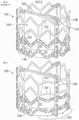
图13是显示扩张的现有技术的可完全扩张的假体心脏瓣膜的立体图;13 is a perspective view of a fully expandable prosthetic heart valve of the prior art showing an expanded;
图14是本申请的改进的可完全扩张的假体心脏瓣膜的立体图;14 is a perspective view of an improved fully expandable prosthetic heart valve of the present application;
图15是显示扩张的现有技术的另一种可完全扩张的假体心脏瓣膜的立面图;15 is an elevational view of another fully expandable prosthetic heart valve of the prior art showing expansion;
图16示例了图15的可完全扩张的假体心脏瓣膜在主动脉瓣环处的放置;Figure 16 illustrates placement of the fully expandable prosthetic heart valve of Figure 15 at the aortic annulus;
图17A和图17B是与图15中所示类似的可完全扩张的假体心脏瓣膜的立面图,其中部分经改进以减少对相邻心脏传导系统的冲击;Figures 17A and 17B are elevation views of a fully expandable prosthetic heart valve similar to that shown in Figure 15, with portions modified to reduce shock to adjacent cardiac conduction systems;
图18是瓣膜递送系统远端上的混和式假体心脏瓣膜/保持器组合的立体图,显示了使用不对称球囊扩张远侧裙部;Figure 18 is a perspective view of the hybrid prosthetic heart valve/retainer combination on the distal end of the valve delivery system, showing the use of an asymmetric balloon to expand the distal skirt;
图19是瓣膜递送管远端上的可完全扩张的假体心脏瓣膜的立体图,显示了使用不对称气囊对其扩张;Figure 19 is a perspective view of a fully expandable prosthetic heart valve on the distal end of the valve delivery tube, showing its expansion using an asymmetric balloon;
图20A是用于扩张如本文改进的心脏瓣膜的不对称球囊的立面图,而图20B是沿图20A中的线20B-20B截取的横截面图;以及Figure 20A is an elevational view of an asymmetric balloon for expanding a heart valve as improved herein, and Figure 20B is a cross-sectional view taken along
图21是用于扩张如本文改进的心脏瓣膜的可选的不对称球囊。Figure 21 is an alternative asymmetric balloon for expanding a heart valve as modified herein.
具体实施方式Detailed ways
如上所述,用于心脏瓣膜置换的一种有前景的现有技术是具有不可扩张瓣膜构件和其上的可扩张支架的混和式瓣膜,尽管仍需要心肺转流术(cardiopulmonary bypass),但可以在短得多的时间框架内被植入。混和式瓣膜被递送通过直接访问(direct-access)端口,通过胸部引入。As mentioned above, one promising prior art for heart valve replacement is a hybrid valve with a non-expandable valve member and an expandable stent thereon, although cardiopulmonary bypass is still required, implanted in a much shorter time frame. The hybrid valve is delivered through a direct-access port, introduced through the chest.
混和式心脏瓣膜Hybrid Heart Valve
图1示例了使用瓣膜递送管或手柄10将现有技术的心脏瓣膜20递送到主动脉瓣环AA的过程的快照。如将看到的,瓣膜递送手柄10具有远侧耦接器12和近侧耦接器14。出于定向的目的,心脏瓣膜20具有向下的流入端和向上的流出端,并且术语近侧和远侧是从先递送瓣膜流入端的外科医生的视角定义的。因此,近侧是向上或流出的同义词,而远侧是向下或流入的同义词。1 illustrates a snapshot of the process of using a valve delivery tube or handle 10 to deliver a prior
同样如图2中示例的,假体心脏瓣膜20被认为是混和型,因为它具有不可扩张、不可皱缩的瓣膜构件30和附接到瓣膜构件30的远端并自其突出的可扩张锚定裙部32。瓣膜构件30可以采取多种形式,并且可以包括布覆盖的丝线型式(丝型件,wireform),其遵循围绕瓣膜周边的起伏(undulating)路径,具有交替的瓣尖(尖突,cusps)33和连合柱34。多个挠性小叶36延伸跨越限定在瓣膜构件30内的总体上圆形的孔口,小叶36中的每一个沿丝线型式,特别是通过两个相邻的连合柱34接受周边支撑。环形的——优选波形的(contoured)——缝纫环或密封环38在大致介于瓣膜构件30与可扩张锚定裙部32之间的轴向位置处环绕瓣膜20。三个标记物39通常在布覆盖的密封环38周围均匀地间隔,以向外科医生标示(勾画,delineate)瓣尖33中每一个的中心。Also as exemplified in FIG. 2 , the
术语“瓣膜构件”指代心脏瓣膜的具有流体阻塞表面以防止血液在一个方向上流动而允许其在另一个方向上流动的部件。可以获得各种构造的瓣膜构件。小叶可以是生物假体的、合成的、或其它适宜形式(expedients)。当用于主动脉瓣置换时,瓣膜构件30优选地具有三个挠性小叶36,其提供流体阻塞表面以替代天然瓣膜小叶的功能。在各种优选实施方式中,小叶可以取自另一个人的心脏(尸体)、牛(牛的)、猪(猪瓣膜)或马(马的)。三个小叶由内部的总体上管状的框架支撑,该框架一般包括用布覆盖以便于小叶附接的一个或多个部件的合成(金属和/或聚合物)支撑结构。The term "valve member" refers to a component of a heart valve that has a fluid blocking surface to prevent blood flow in one direction and allow it to flow in another direction. Valve members are available in various configurations. Leaflets can be bioprosthetic, synthetic, or other expedients. When used in aortic valve replacement, the
尽管示例性心脏瓣膜20如所述构造,但本发明更加宽泛并且涵盖任意瓣膜构件30——其可扩张锚定裙部32自其流入端突出(例如,不具有丝线型式的瓣膜构件30)。Although the
出于定义目的,术语“裙部”或“锚定裙部”是指心脏瓣膜的能够附接到心脏瓣环组织的可扩张结构部件。本文所述的锚定裙部32可以是管状或锥形的,并且具有不同的形状或直径。For definition purposes, the term "skirt" or "anchoring skirt" refers to an expandable structural component of a heart valve that can be attached to the heart valve annulus tissue. The anchoring skirts 32 described herein can be tubular or tapered, and have different shapes or diameters.
与使用大量缝线的常规缝纫程序相比,通过利用耦接到不可扩张瓣膜构件30的可扩张裙部32,植入操作的持续时间大大减少。可扩张裙部32可以简单地径向向外扩张以与植入部位接触,或可被提供有另外的锚定装置,如倒钩(barbs)。这提供了快速连接手段,因为它不需要将瓣膜完全缝合在瓣环周围的耗时过程。可以使用常规的心脏直视途径和心肺转流术实施操作。在一个有利的特征中,由于植入可扩张支架的相对速度,转流时间大大减少。By utilizing the
作为进一步定义的一点,术语“可扩张的”在本文中用于指代能够从第一递送直径扩张到第二植入直径的心脏瓣膜的部件。因此,可扩张的结构不意指可能因温度升高或其它此类偶然原因(如作用于小叶或连合的流体动力学)而经历略微扩张的结构。相反,“不可扩张的”不应解释为意指完全刚性或尺寸上稳定,而只是瓣膜构件不像某些所提出的微创或经皮递送的瓣膜那样可扩张/可皱缩,并且可以观察到例如常规“不可扩张的”心脏瓣膜的某种略微扩张。As a point of further definition, the term "expandable" is used herein to refer to a component of a heart valve that is capable of expanding from a first delivery diameter to a second implantation diameter. Thus, an expandable structure is not intended to mean a structure that may undergo slight expansion due to elevated temperature or other such accidental causes, such as hydrodynamics acting on the leaflets or commissures. Conversely, "non-expandable" should not be interpreted to mean completely rigid or dimensionally stable, but simply that the valve member is not as expandable/retractable as some of the proposed minimally invasive or percutaneously delivered valves, and can be observed To eg some slight expansion of conventional "non-expandable" heart valves.
在下面的描述中,术语“身体通道”用于定义身体内的血液管道或血管。当然,假体心脏瓣膜的特定应用决定了所讨论的身体通道。例如,主动脉瓣置换物将被植入在主动脉瓣环内或邻近主动脉瓣环植入。同样,二尖瓣置换物将被植入在二尖瓣环处。本发明的某些特征对于一个植入部位或另一个,特别是主动脉瓣环而言特别有利。然而,除非该组合在结构上是不可能的,或者被权利要求语言排除,否则本文描述的任意心脏瓣膜实施方式都可以被植入在任意身体通道中。In the following description, the term "body passage" is used to define blood conduits or vessels within the body. Of course, the specific application of the prosthetic heart valve determines the body passage in question. For example, an aortic valve replacement would be implanted within or adjacent to the aortic valve annulus. Likewise, a mitral valve replacement will be implanted at the mitral valve annulus. Certain features of the present invention are particularly advantageous with respect to one implantation site or the other, particularly the aortic valve annulus. However, unless the combination is structurally impossible, or excluded by claim language, any of the heart valve embodiments described herein may be implanted in any body passageway.
在特别优选的实施方式中,假体瓣膜20包括商业可获得的不可扩张的假体瓣膜构件30,如可从Edwards Lifesciences获得的Carpentier-Edwards PERIMOUNT


在图2的剖开部分中,三个小叶36中的每一个都包括向外突出的凸耳(tabs)40,凸耳40穿过起伏的丝线型式的倒U形连合柱42并缠绕内聚合物带的布覆盖的直立柱44。相邻小叶的凸耳40会聚在丝线型式连合柱42的外部并缝纫在一起从而为小叶自由边缘46提供外锚定件。在使用时,如图2中所示,流体力使小叶闭合(对合)并在阻塞的瓣膜上施加大大的力,这转化为小叶自由边缘46上的向内力。缝纫在一起的缠绕的小叶凸耳40和布覆盖的柱44的组合件提供了实体锚定件,金属丝线型式柱42防止该实体锚定件向内移动。一定的挠曲是可以接受的,并且甚至是期望的。In the cut-away portion of Figure 2, each of the three
瓣膜构件30的经常使用的一个特征是围绕其流入端的缝纫环或密封环38。密封环38与锚定裙部32的上端共形并且位于裙部与瓣膜构件30的接合处。此外,密封环38呈现向外的凸缘,其接触瓣环部分的流出侧,而锚定裙部32扩张并接触相对的瓣环的心室侧,因此从两侧将心脏瓣膜20固定到瓣环。此外,密封环38的存在为外科医生提供了使用常规缝线将心脏瓣膜20固定到瓣环——作为应急措施——的机会。A frequently used feature of
优选的密封环38限定了起伏的上面或流出面和起伏的下面。瓣膜结构的瓣尖33毗邻密封环38上面中的谷(valleys),谷与下面限定峰的位置相对。反过来,瓣膜连合柱34与密封环38下面限定谷或槽的位置对准。密封环38的起伏形状有利地匹配瓣环AA的主动脉侧的解剖学轮廓,即,环上架(supra-annular shelf)。环38优选地包括缝线可透过的材料,如卷制的(rolled)合成织物或由合成织物覆盖的硅酮内芯。在后一种情况下,硅酮可以被模塑以限定起伏的轮廓并且织物覆盖物在其上共形。The
如图2中所见,锚定裙部32包括组装在织物54的管状区段内的内支架框架52,织物54的管状区段则围绕支架框架,从里到外被拉紧,并缝纫到其上以形成布覆盖的裙部32。更厚、更长毛绒的织物凸缘56也可以附接在织物54周围来提供另外的瓣周密封益处。应该注意的是,图2显示了处于向外扩张状态的支架框架52,如上所述,这发生在植入期间和之后。As seen in FIG. 2, the anchoring
在组装过程中,支架框架52最初可以是管状的,然后被折绉成锥形形状,例如,如图2A中所示。当然,框架52可以先被折绉然后再用布覆盖,反之亦然。图2B显示了分离的并扩张成其植入形状的扩张后的支架框架52,植入形状总体上是锥形的并且在下端处略微向外张开。During assembly, the
再次参考图1的植入步骤,主动脉瓣环AA示意性地显示为分离的并且其应该被理解成为清楚起见未显示各种解剖学结构。瓣环AA包括从周围的心脏壁向内突出的组织的纤维环。瓣环AA限定了升主动脉AO和左心室LV之间的孔口。尽管未显示,但天然小叶在瓣环AA处向内突出以在孔口处形成单向阀。小叶优选地保持原位并被可扩张锚定裙部32向外压缩,或者在一些情况下可以在程序之前被移除。如果小叶被移除,钙化的瓣环中的一些也可以诸如用咬骨钳移除。升主动脉AO始于瓣环AA,具有三个向外的凸起或窦,其中两个以冠状动脉口(开口)为中心,通向冠状动脉CA。重要的是定向假体瓣膜20,使得连合柱34不与冠状动脉口对准并因此不阻塞冠状动脉口。Referring again to the implantation step of Figure 1, the aortic valve annulus AA is schematically shown separated and it should be understood that various anatomical structures are not shown for clarity. The annulus AA includes an annulus fibrosus of tissue protruding inward from the surrounding heart wall. The valve annulus AA defines the orifice between the ascending aorta AO and the left ventricle LV. Although not shown, the native leaflets project inwardly at the annulus AA to form a one-way valve at the orifice. The leaflets preferably remain in place and are compressed outward by the
图1显示了多条预先安装的引导缝线50。外科医生在主动脉瓣环AA周围三个均等间隔的位置处附接引导缝线50。在示例的实施方式中,引导缝线50附接到低于或对应于天然瓣尖的最低点或窦的位置。引导缝线50穿过瓣环AA并离开植入位点返回。当然,根据外科医生的偏好,可以使用其它缝合方法或垫片(pledgets)。FIG. 1 shows a plurality of pre-installed guide sutures 50 . The surgeon attaches guide sutures 50 at three equally spaced locations around the aortic annulus AA. In the exemplary embodiment, the
引导缝线50以成对的自由长度从瓣环AA延伸并离开操作位点。假体心脏瓣膜20安装在递送手柄10的远端,并且外科医生沿着引导缝线50将瓣膜推进到主动脉瓣环AA内的位置。即,外科医生将三对引导缝线50穿线通过缝线可透过的环38周围均等间隔的位置。如示例的,如果引导缝线50锚定到主动脉窦下方的瓣环AA处,则它们在瓣膜连合柱34之间的中路,具体是在密封环的瓣尖区域33处穿线通过环38,瓣尖区域33在轴向上可以比连合位置更厚,或者在圆周各处都是均匀的。Guide sutures 50 extend in pairs of free lengths from the annulus AA and away from the site of operation. The
图1示例了瓣膜递送手柄10的双重性质,即它既提供了递送系统的手柄的一部分,又提供了直接通过保持器22和小叶分离构件(下文描述)到达锚定裙部32内的空间的通腔。尽管未显示,但递送系统的其它元件与近侧耦接器14配合以提供细长的访问通道,用于将诸如球囊之类的扩张器递送到锚定裙部32内的空间。Figure 1 illustrates the dual nature of valve delivery handle 10 in that it provides both part of the handle of the delivery system and direct access to the space within
外科医生推进心脏瓣膜20直到它停留在主动脉瓣环AA处所期望的植入位置。起伏的缝线可透过的环38期望地接触瓣环AA的升主动脉AO侧,因此被称为处于环上位置。这样的位置相比将环38(根据定义,其围绕瓣膜孔口)放置在瓣环AA内或环下放置,使得能够选择更大孔口的假体瓣膜20。递送程序的进一步细节在2011年6月23日提交的美国专利号8,641,757中显示和描述,其内容明确并入本文。The surgeon advances the
在使假体心脏瓣膜20落座(seating)在主动脉瓣环AA处之后,锚定裙部32诸如用球囊扩张成与主动脉瓣环的瓣下方面(subvalvular aspect)接触,以将瓣膜20锚定到瓣环AA并密封主动脉瓣环/LVOT和生物假体之间的同心空间以防止瓣周漏。然后,操作者切断保持器22和瓣膜20之间的任何保持缝线(未显示),使球囊瘪缩并将其连同小叶分离构件、保持器22和瓣膜递送手柄10的整个组合件一起撤回。最后,引导缝线50将被打结以进一步将瓣膜固定就位。After seating the
在图2A和图2B中详细看到的内支架框架52可能类似于在Edwards
应当注意,图2A中的支架框架52在其上端62处以总体上管状形状开始,然后向内成角度以朝向其下端64呈锥形。即,总体上管状的部分具有高度h,其仅为总高度H的一部分。如图所示,管状部分具有高度h,其总体上对应于支架框架的上端62的槽60a和峰60b之间的高度。上端62优选地由用于加强的较粗的线材限定。上端62遵循交替的弓形槽60a和尖峰60b的起伏路径,其总体上对应于缝纫环38下侧的起伏轮廓(参见图3A)。期望地,峰60b在槽60a上方的高度h在支架框架总高度H的约25-36%之间,对于较大的瓣膜尺寸,该比例逐渐增加。It should be noted that the
仍然参考图2A,锚定裙部32的收缩后的支架框架52在制造后具有锥形构型的初始形状,其中下(流入/前导)端64限定比上(流出/拖尾)端62描述的更小的第一直径D1孔口。如所述,锚定裙部32附接到瓣膜构件30的流入端,一般经由通过支架框架52的上端62的连接到瓣膜构件30或缝纫环38上的织物的缝线。如图3A所示的特定的缝纫环38包括起伏的流入轮廓,该流入轮廓在瓣膜瓣尖33的区域中向下倾斜(dips)或沿流入方向倾斜,而在瓣膜连合34的区域中沿流出方向向上呈弧形。这种起伏形状总体上遵循向下落座在缝纫环38内的心脏瓣膜构件丝线型式50的流入端(参见图2)。支架框架52的扇形上端62也与这种起伏形状共形,其中峰60b与瓣膜连合34对准并且谷60a与瓣膜瓣尖33对准。Still referring to FIG. 2A , the
框架52的中间区段具有在轴向延伸的支柱68之间呈锯齿样式的三排可扩张支柱66。轴向延伸的支柱68与支架框架的上端62的峰60b和槽60a同相。由较粗线材上端62限定的加强环围绕其周边是连续的并且具有被眼孔70中断的基本上恒定的厚度或线材直径,眼孔70可用于在瓣膜构件30和裙部32之间附接缝线。注意,附接缝线确保裙部32的上端62的峰紧密配合位于瓣膜的连合下方的缝纫环38的槽。The middle section of
如图2B中所见,被覆盖的裙部32的上端62的最小直径d将总是大于由其附所接的假体瓣膜构件30所限定的ID(其限定瓣膜孔口和相应标记的瓣膜尺寸)。例如,如果上端62固定到围绕瓣膜的支撑结构的缝纫环38的下侧,则根据定义,它将等于或大于支撑结构的ID或流动孔口。然而,一般地,上端62经由缝线附接到覆盖内支架结构(未显示)的织物,织物的一部分是内聚合物带44。As seen in Figure 2B, the minimum diameter d of the
图2B示例了分离的且处于其扩张构型的支架框架52。球囊膨胀被设计为仅使框架的流入端或下端64扩张,并且不会在流出端或上端62上施加扩张载荷以防止损坏瓣膜的环上元件,因此环上瓣膜保持尺寸不变。现有技术支架框架52的流入端64被设计成当球囊膨胀时对称地和径向地扩张。下端64的直径D2大于上端62的直径。借助于用球形球囊扩张,支架52的扩张后的形状还优选地朝向其下端64略微向外张开,如图所示。这种形状有助于支架共形于在主动脉瓣下方的左心室的瓣下轮廓,因此有助于将瓣膜固定就位。Figure 2B illustrates
心脏的传导系统conduction system of the heart
如上所述,重要的是要确保扩张的支架框架52良好地密封植入物和LVOT之间的空间,并且它不碰撞心脏的传导系统,从而影响其功能。实际上,这种担忧不限于本文示例的混和式假体心脏瓣膜20,而是适用于任何可扩张瓣膜,特别是具有可球囊扩张的支架的瓣膜。As mentioned above, it is important to ensure that the expanded
如图3所示,心脏的传导系统并非均匀分布在天然心脏瓣膜周围,而是集中在几个区域。心脏的心脏传导系统或脉冲传导系统总体上由四个结构组成:1.窦房结(SA结)2.房室结(AV结)3.分支为左支和右支的房室束(AV束),和4.心肌壁中的浦肯野纤维(未示例)。构成这些结构的心肌纤维专门用于脉冲传导,而不是对收缩用肌肉纤维的正常特化(normal specialization)。脉冲始于SA结,SA结有时被描述为心脏的起搏器并且位于右心房的上部。自那里,信号传递通过结间束(internodal tracts)到达位于右心房下部的AV结,通过腔室之间的中心纤维组织中的AV束,并到达左心室和右心室心肌组织中的纤维。As shown in Figure 3, the conduction system of the heart is not evenly distributed around the native heart valve, but concentrated in several areas. The cardiac conduction system or impulse conduction system of the heart is generally composed of four structures: 1. the sinoatrial node (SA node) 2. the atrioventricular node (AV node) 3. the atrioventricular bundle (AV) branching into the left and right branches bundles), and 4. Purkinje fibers in the myocardial wall (not shown). The myocardial fibers that make up these structures are specialized for impulse conduction, rather than the normal specialization of muscle fibers for contraction. The pulse begins at the SA node, which is sometimes described as the heart's pacemaker and is located in the upper part of the right atrium. From there, signaling travels through internodal tracts to the AV node located in the lower part of the right atrium, through the AV tracts in the central fibrous tissue between the chambers, and to fibers in the left and right ventricular myocardial tissue.
图3显示了邻近主动脉瓣的AV结。传导束(希氏束)横贯膜间隔到室间隔。在其过程中,左束支更靠近右冠状动脉瓣环并通过束和浦肯野纤维使左心室受神经支配。右束支从膜间隔离开,穿透间隔上部并到达室间隔右侧,通向右心室及其束和浦肯野纤维。许多解剖学研究已经试图绘制(map)这些传导纤维在心脏腔室内和周围的行程(course)。Figure 3 shows the AV node adjacent to the aortic valve. Conductive bundles (His bundles) traverse the membranous septum to the interventricular septum. During its course, the left bundle branch is closer to the right coronary annulus and innervates the left ventricle through the bundle and Purkinje fibers. The right bundle branch departs from the membranous septum, penetrates the upper part of the septum and reaches the right side of the interventricular septum, leading to the right ventricle and its bundles and Purkinje fibers. Numerous anatomical studies have attempted to map the course of these conducting fibers in and around the heart chambers.
参考图4中主动脉瓣的平放描绘,与主动脉瓣相邻的传导通路一般被理解成位于右冠状窦和非冠状窦之间的瓣下区域。此传导系统区被示意性地描绘成在这两个窦之间向上延伸并向下扩展到左心室中的三角形地区。传导系统区的精确位置、深度和横向跨度因患者而异,但是该区始于瓣环下方希氏束出现的深度,并且该深度被认为在患有主动脉瓣狭窄的患者中会减少。一些临床结果表明,深度——希氏束在其下方出现——越短,传导异常的风险就越高。另一方面,更长的深度表明瓣环到希氏束的距离更长,其可允许更长和更宽的心脏瓣膜植入物而不必引起传导异常。Referring to the flat depiction of the aortic valve in Figure 4, the conduction pathway adjacent to the aortic valve is generally understood to be the subvalvular region between the right coronary sinus and the non-coronary sinus. This conduction system region is schematically depicted as a triangular region extending up between the two sinuses and down into the left ventricle. The exact location, depth, and lateral span of the conduction system region varies from patient to patient, but the region begins at the depth where the bundle of His appears below the annulus and is thought to decrease in patients with aortic stenosis. Some clinical results suggest that the shorter the depth - below which the bundle of His emerges - the higher the risk of conduction abnormalities. On the other hand, longer depths indicate a longer distance from the annulus to the His bundle, which may allow for longer and wider heart valve implants without necessarily causing conduction abnormalities.
图5示例了一般的混和式假体心脏瓣膜,如图2中所示的瓣膜20的轮廓。虚线100指示出三个挠性小叶的支撑结构的起伏形状。下圆圈102是连接支撑结构的下弓形瓣尖的假想线,该假想线意图在植入时位于冠状窦的下端。这两条线100、102总体上描述了常规外科瓣膜的轮廓。以104指示的下锥形形状对应于扩张后的瓣下支架或裙部,如图2中关于瓣膜20所示的裙部32的轨迹(footprint)。FIG. 5 illustrates a general hybrid prosthetic heart valve, such as the outline of
现在参考图6,与图5相同的混和式假体瓣膜的大体轮廓叠加在平放的主动脉瓣环上,就好像被植入一样。由虚线100限定的瓣膜的三个直立柱在三个窦——右侧窦、非冠状窦和左侧窦——之间向上延伸。下圆圈102在这些窦的正下方延伸,并且瓣下裙部形状104抵靠左心室的内侧平放。此叠加示例了干扰传导系统区的可能来源所在的位置。即,将裙部32扩张到右冠状窦和非冠状窦之间的三角形传导系统区(阴影区域)中可能会冲击心脏的传导系统。Referring now to FIG. 6, the general outline of the same hybrid prosthetic valve as in FIG. 5 is superimposed on the aortic annulus lying flat, as if implanted. The three upright posts of the valve, defined by dashed
图7是主动脉瓣的示意性平面图,指示了相邻传导系统部件的近似位置。即,左束支和希氏束嵌入在主动脉瓣后侧上的膜状室间隔正外侧的心脏组织中。如上所述,传导系统部件的正常位置邻近右冠状窦或瓣尖(RCS)与非冠状窦或瓣尖(NCS)之间的瓣膜连合。此位置有助于了解对假体瓣膜的改进,如下所述。Figure 7 is a schematic plan view of the aortic valve indicating the approximate locations of adjacent conduction system components. That is, the left bundle branch and the bundle of His are embedded in the cardiac tissue just outside the membranous septum on the posterior side of the aortic valve. As noted above, the normal location of conduction system components is adjacent to the valve commissure between the right coronary sinus or cusp (RCS) and the noncoronary sinus or cusp (NCS). This location is helpful in understanding improvements to prosthetic valves, as described below.
混和式心脏瓣膜改进Hybrid Heart Valve Improvement
图8是经改进以避免干扰心脏传导系统的组装后的混和式假体主动脉心脏瓣膜20’的立体图。具体地,可扩张裙部32’将如下文所述进行改进。优选的改进涉及对裙部32’的内支架框架——仅围绕其部分圆周——的改进。改进的部分对应于将会邻近传导系统,或大致邻近右冠状窦或瓣尖(RCS)与非冠状窦或瓣尖(NCS)之间的瓣膜连合植入的部分,如图7所示。为了在瓣膜20’的植入期间引导外科医生,在其外部提供标记物以指示旋转放置。即,外科医生可以在视觉上辨别主动脉瓣周围的解剖学特征,但由于外布覆盖物54’、56’,支架框架的经改进的部分将不明显。Figure 8 is a perspective view of an assembled hybrid prosthetic aortic heart valve 20' modified to avoid interference with the cardiac conduction system. Specifically, the expandable skirt 32' will be modified as described below. A preferred modification involves modification to the inner stent frame of skirt 32' around only a portion of its circumference. The modified portion corresponds to the portion that will be implanted adjacent to the conduction system, or approximately adjacent to the valve commissure between the right coronary sinus or cusp (RCS) and the non-coronary sinus or cusp (NCS), as shown in FIG. 7 . To guide the surgeon during implantation of the valve 20', markers are provided on its exterior to indicate rotational placement. That is, the surgeon can visually discern the anatomical features around the aortic valve, but the modified portion of the stent frame will not be apparent due to the
常规的主动脉心脏瓣膜一般在其周边具有三个不同的标记物,向外科医生指示瓣尖区域33,如图2中在39处所示。具体地,粗的黑色标记线用于形成标记物39。改进的瓣膜20’还具有三个瓣尖标记物39’,以及在瓣尖标记物39’中的两个之间延伸的有区别的细长标记物72。细长标记物72因此围绕改进的瓣膜20’延伸约1/3的路径(120°)并且与裙部32’的支架框架的改进的弓形跨度对准。当外科医生植入瓣膜20’时,他或她旋转线性标记物72以与解剖结构中传导系统所在的部分对准。如上面参考图7说明的,传导系统预期邻近右冠状窦或瓣尖(RCS)与非冠状窦或瓣尖(NCS)之间的瓣膜连合定位。因此,弓形标记物72以瓣膜连合柱42’为中心。细长标记物72可以由印刷指示器(printed indicator)形成,或者通过沿着适当区域缝纫一个或多个长度的缝线来形成。细长标记物72被着色以与密封环38’形成高度对比,如针对白色布覆盖物的黑色标记缝线。也可以使用明亮的或荧光的颜色,在昏暗的照明下更加可见。Conventional aortic heart valves typically have three different markers around their perimeter, indicating the
图9A-图9C是用于混和式假体心脏瓣膜的锚定裙部的本申请示例性支架框架52a、52b、52c的立面图,支架框架显示为径向扩张,其中支柱经改进以减少对相邻心脏传导系统的冲击。应当注意,支架框架的构造与上述图2A的支架框架52大体相同,除了下面的改进之外,因此相同的元件将具有相同的数字并添加上标符号(例如,62’)。9A-9C are elevation views of
在图9A中,支架框架52a显示具有较粗的线材上端62’,上端62’具有交替的槽60a’和峰60b’的起伏周边。当收缩时,支架框架52a在其上端62’具有总体上管状形状,然后向内成角度以朝向其下端64’呈锥形。当扩张时,下端64’如图所示径向向外扩张,具有张开的构型。像前文一样,框架52a的中间区段具有呈锯齿样式的三个周向排的可扩张支柱66’,在轴向延伸的支柱68’之间具有V形弯曲部。轴向延伸的支柱68’与支架框架的上端62’的峰60b’和槽60a’同相。In Figure 9A,
在以峰60b’中的一个为中心的支架框架52a的区域120a(用括号所括的)中,三排可扩张支柱66’在支架框架52a的扩张状态下于锯齿样式的弯曲部中展现出比框架的其余部分更浅(更大)的夹角θ。更准确地,弯曲部在槽60a’中的两个之间延伸约120°的区域120a中更浅。总体上,区域120a可以沿周向介于约90-120°之间延伸。在示例性实施方式中,区域120a中的弯曲部的夹角在约135-160°之间,而支架框架其余部分周围的可扩张支柱66’的排中的弯曲部在约45-90°之间。结果就是,在被拉直和拉长时,区域120a中的可扩张支柱66’的排比支架框架52a的其余部分周围的排扩张得更少。换句话说,它们拉直得更快,如扩张后的框架中的弯曲部的最终角度θ与其余的弯曲部对比所示。这产生了支架框架52a的不对称扩张,其中约2/3的框架正常扩张而约1/3的扩张得较少。区域120a在扩张时形成略微几分(something of)弓弦形状,在圆形相邻区域之间延伸,如图12B中最佳所示。In
应当注意,扩张后的框架52a中的弯曲部的最终角度θ一般与区域120a中的支架框架在最初形成时的弯曲部角度相同。即,框架52a被制造成管状形状,然后在包装和运输前被折绉到较小的直径,因为支架框架是在收缩状态下递送的。因此,在框架形成时设定框架52a的最终弯曲部角度θ。一种框架构造的方法是从可塑性扩张材料(如不锈钢)或弹性材料(如镍钛诺)的管状坯料激光切割各种支柱。It should be noted that the final angle Θ of the bend in the expanded
在一个实施方式中,支架框架52a的大部分被配置成正常向外张开到比公称(nominal)心脏瓣膜尺寸大几毫米的最大直径。“公称心脏瓣膜尺寸”意指针对该特定瓣环选择的标记的心脏瓣膜尺寸,并且通常以奇数mm增量对应于原始心脏瓣膜孔口的测量直径。“公称心脏瓣膜尺寸”还略小于支架框架52a的上端62’的直径d。例如,“公称心脏瓣膜尺寸”可以是21mm,而支架框架52a的下端64’向外张开到约23.5mm的最大直径。然而,以峰60b’中的一个为中心的支架框架52a的区域120a被配置为向外扩张少1-2mm之间,或向外扩张到介于约21.5-22.5mm之间的直径。这有助于减少施加到周围瓣下区域——假设传导系统在此处——的力。In one embodiment, the majority of
在对潜在对传导系统冲击的另一种解决方案中,图9B显示了支架框架52b,其中在以峰60b’中的一个为中心的支架框架52b的区域120b(用括号所括的)中移除了下周向排的可扩张支柱66’。在示例的实施方式中,与支架框架52a一样,区域120b围绕瓣尖之间支架框架周边的1/3延伸或延伸约120°。更大致地,区域120b可以沿周向介于90-120°之间延伸。区域120b中的弯曲部的夹角保持与框架的其余部分一样,在约45-90°之间,因此区域120b的具有周向支柱66’的那部分正常扩张。如上所述,在一些患者中,邻近主动脉瓣的电传导系统直到某些路径向下进入左心室中才开始,在这种情况下,支架框架52b的扩张可以避免均匀地(even)接触该区。In another solution to potential shock to the conduction system, Figure 9B shows
最后,图9C显示了第三种可选的支架框架52c,其在区域120c(用括号所括的)中也移除了下周向排的可扩张支柱66’。另外,区域120c中的下一相邻周向排的可扩张支柱66’在支架框架52c的扩张状态下具有浅的所夹的弯曲部角度,例如在上文关于图9A支架框架52a的弯曲部的夹角所阐述的范围内。因此,当支架框架52c扩张时,由于下排缺失,因此可以完全避开传导系统区,并且下一相邻排的支柱66’比支架框架的其余部分扩张得少(例如,不对称径向扩张),这减少了该区上的向外压力。像前文一样,区域120c优选地在槽60a’中的两个之间沿周向介于约90-120°之间延伸并且以峰60b’中的一个为中心。Finally, Figure 9C shows a third
图10是另一个示例性支架框架52d的立面图,支架框架52d径向扩张,其中支柱经改进以产生围绕裙部的不对称扩张。在此实施方式中,区域120d(用括号所括的)中的下周向排的可扩张支柱66’具有可变的所夹的弯曲部角度,其中朝向区域120d的中心的角度更浅。具体地,可以存在与支架框架的上端62’的峰60b’和槽60a’同相的十八个轴向延伸的支柱68’,这意味着每1/3中有六个,将区域120d划分为六个跨度,跨越每一个跨度在可扩张支柱66’中都有弯曲部。里面的两个跨度具有较浅(大)的弯曲部角度,而接下来的两个向外的跨度具有较小的弯曲部角度,而最外侧的两个跨度具有甚至更小的弯曲部角度。里面的两个跨度拉直得最快,如最终角弯曲部角度θ所示,接下来的两个向外的跨度拉直得较少,如最终弯曲部角度α所示,而最外侧的两个跨度有更多扩张空间,如其最终弯曲部角度β所示。这改变了不对称扩张,使得区域120d中最终直径的减小从相邻的未改变区域渐进。更具体地,与相邻区域之间的更具弦形的形状(就图9A的实施方式而言)相比,区域120d的扩张后的形状更加圆润,更接近支架框架52d的其余部分的圆形形状。这关注的是区域120d的中心的扩张减小,区域120d又可以沿周向介于90-120°之间延伸。当然,所夹的弯曲部角度的具体变化模式可以改变,而所示例的实施方式仅仅是示例性的。10 is an elevational view of another
图11A和图11B是另一示例性支架框架52e的立面图,支架框架52e显示径向扩张,其中在区域120e(用括号所括的)中移除了中间周向排的可扩张支柱66’以减少对相邻的天然传导系统区的冲击。图11A显示了所有轴向延伸的支柱68’被保留以在支柱之间形成多个扩大的空间或单元122,而在图11B中它们中的一些被移除以形成多个甚至更大的单元124。在两种支架框架52e中,区域120e期望地以峰60b’中的一个为中心并且优选地沿周向延伸约120°,更大致地介于90-120°之间延伸。这些实施方式因此在区域120e内产生更大的单元或空隙,虽然正常扩张,但减少了支架与周围天然传导系统区的直接接触。当然,区域120e中剩余排的可扩张支柱66’的所夹的弯曲部角度也可以很浅,如上所述,以产生不对称的径向扩张并进一步减少对传导系统的冲击。FIGS. 11A and 11B are elevation views of another
图12A从下方显示扩张前的支架框架52a,而图12B显示扩张后的支架框架52a,显示了一侧是如何不与其余部分扩张得一样远的(例如,不对称径向扩张)。具体地,区域120a包括比支架框架52a的其余部分更浅的弯曲部夹角θ,因此球囊扩张导致该区域120a以弓弦形状扩张得比圆形形状——就支架框架周边的其余部分而言——更多。距围绕最大直径扩张所绘制的假想圆圈的距离ΔD是区域120a中优选的扩张直径上的减小。如上所述,距离ΔD优选地在1-2mm之间,且更优选地约1.5mm。不对称区域120a中扩张直径的这种小的减小被认为足以减少对传导系统的负面冲击。Figure 12A shows
可完全扩张的心脏瓣膜改进Fully expandable heart valve improvements
图13是显示为扩张的现有技术的可完全扩张的假体心脏瓣膜140的立体图。心脏瓣膜140是许多这样的瓣膜,特别是由加利福尼亚州尔湾的Edwards Lifesciences出售的
结构框架142可从收缩构型完全扩张至所示的扩张形状。以这种方式,收缩的瓣膜140可以通过狭窄通道(如通过导管或其它递送)被推进到目标瓣环处的位置中,而无需使心脏停止并将患者置于心肺转流术下。然后将收缩的瓣膜140从导管或其它递送管中排出并扩张以与瓣环接触。框架142可以是自扩张的,或者像在
图14是本申请的改进的可完全扩张假体心脏瓣膜160的立体图。瓣膜160在大多数方面与图13的代表性心脏瓣膜140具有相同的构造,因此相同的元件被赋予相同的数字并添加上标符号(例如,142’)。像前文一样,瓣膜160包括支撑多个(例如,三个)挠性小叶144’的可扩张框架142’。再一次,相邻的小叶144’在框架142’的连合柱148’处彼此抵靠固定。14 is a perspective view of an improved fully expandable
框架142’具有沿周向延伸的区域162(用括号所括的),其中周向支柱152’中的弯曲部156’具有比框架其余部分周围的弯曲部154’大得多的夹角。这种改进减少了区域162中框架152’周向扩张的量并因此减少径向扩张的量。当瓣膜160扩张时,这种减少的或不对称的扩张有助于减少与心脏的相邻传导系统的接触并因此减少对心脏的相邻传导系统的冲击。如果心脏瓣膜160意图用于植入在主动脉瓣环处,则当传导系统被认为集中在天然连合中的一个附近时,区域162以连合柱148’中的一个为中心。为了帮助外科医生在植入期间旋转地定向心脏瓣膜160,可以在适当的连合柱148’上或在该位置处的织物裙部146’上放置标记物。尽管未显示,但标记物可以是如上文关于图8所描述的那样(例如,跨越120°的深色缝线标记物)。Frame 142' has a circumferentially extending region 162 (enclosed in parentheses) with bends 156' in circumferential struts 152' having a much larger included angle than bends 154' around the remainder of the frame. This improvement reduces the amount of circumferential and therefore radial expansion of frame 152' in
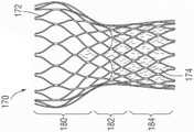
图15是显示为扩张的现有技术的另一种可完全扩张的假体心脏瓣膜170的立面图。心脏瓣膜170总体上包括自扩张结构框架172,组织瓣膜174缝纫至自扩张结构框架172。在一个这样的实施方式中,可从明尼苏达州明尼阿波利斯的Medtronic Cardiovascular获得的EvolutTM TAVR系统包括具有猪心包组织瓣膜的环上、自扩张镍钛诺框架。结构框架172略微是沙漏形并且限定了扩大的上部区域180、狭窄的中间区域182和扩大的下部区域184。15 is an elevational view of another fully expandable
自扩张镍钛诺框架172可以刚好在递送前被折绉到小直径。如图16所示,在将可完全扩张的假体心脏瓣膜170植入在主动脉瓣环后,上部区域180扩大到升主动脉中,狭窄的中间区域182与主动脉瓣环AA套准(registers),而下部区域184扩大到左心室LV中或瓣下区域中。尽管框架172是自扩张的并因此在周围组织上施加较小的向外力,但是因与心脏的相邻传导系统接触——尤其是在瓣下区域中——而可能出现问题。此外,许多外科医生对中间区域182执行植入后球囊扩张以帮助使框架172完全扩张,这也可能对传导系统产生负面冲击。The self-expanding
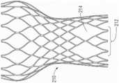
因此,图17A和图17B显示了用于与图15所示一样的可完全扩张的假体心脏瓣膜的可自扩张支架框架,其中一部分经改进以减少对相邻心脏传导系统的冲击。具体地,图17A中的支架框架200的特征在于区域202(用括号所括的)具有导致框架不对称扩张的经改进的支柱;即,与圆周的其余部分相比,区域202内的扩张较少。有许多方式来改进支柱以实现这一点,其中一种包括在短的V形段206所连接的支柱之间的较小的单元204。形成较小的单元204的支柱206略微扩张,但不如周围支柱扩张得多。如果使用支架框架200的瓣膜用于主动脉瓣置换,则区域202优选地以瓣膜连合中的一个为中心,并且可以围绕瓣膜沿周向延伸90-120°之间。另外,改进区域202优选位于瓣下区域中,优选位于下部区域184(如图15中所见)中,但也可能向上延伸到中间区域182中。Accordingly, Figures 17A and 17B show a self-expandable stent framework for a fully expandable prosthetic heart valve as shown in Figure 15, with portions modified to reduce shock to adjacent cardiac conduction systems. Specifically,
另一方面,图17B示例了可自扩张支架框架210,其中通过移除多个支柱形成扩大的单元214改进了区域212(用括号所括的)以减少对相邻传导系统的冲击。在示例的实施方式中,两个扩大的菱形单元214是通过将两个位置中的四个相交的支柱移除而形成的,但也考虑了其它样式。支柱的移除减少了扩张框架210将会接触并负面冲击相邻传导系统的机会。再一次,对于主动脉瓣置换来说,区域212优选地以瓣膜连合中的一个为中心,并且可以围绕瓣膜沿周向延伸90-120°之间,并且优选地位于瓣下区域中。214处的扩大的单元与采用图17A的支架200的不对称扩张的组合也是可能的。17B, on the other hand, illustrates a self-
改进的扩张球囊Improved dilation balloon
图18是瓣膜递送系统220的立体图,与上文关于图1所描述的类似,在其远端上具有混和式假体心脏瓣膜222。像前文一样,心脏瓣膜222的远侧裙部的扩张是使用延伸通过瓣膜222中间的球囊224来完成的。与现有系统不同,球囊224被改进成不对称扩张,其中在226处的大部分圆周是常规的并且具有改变的区域228。具体地,区域228被改变以相比较大的区域226扩张得更少。因此,心脏瓣膜222邻近经改进的区域228的那部分裙部也扩张得更少。18 is a perspective view of a
可以以多种方式改进区域228以经历较小的径向扩张。一种方式是将球囊224构造成具有由顺应性(例如,有弹性的)球囊材料形成的较大区域,其中区域228由非顺应性(例如,非弹性)材料形成。两种类型的材料的各种球囊是已知的,一般由尼龙,例如,聚醚嵌段酰胺(例如,
此外,球囊224可以与如上所讨论的改进的混和式瓣膜组合,并且使区域228对准以在支架框架的改进区域内扩张。例如,区域228可以沿周向介于90-120°之间延伸,并且在图9A中的支架框架52a的区域120a内(或在其它改进的支架框架中的任意处内)对准。尽管各种改进的支架框架意图不对称地扩张,但改进区域可以只是将框架的其余部分朝向该区域牵拉,从而导致所期望的较少的不对称性。因此,可能需要使用改进的扩张球囊224来产生所期望的不对称性。Additionally, the
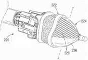
图19是瓣膜递送系统230——包括导管232和在可完全扩张的假体心脏瓣膜236内的不对称球囊234——的远端的立体图。球囊234优选地具有正常扩张的大部分区域238和不对称扩张的改进区域240。改进区域240可以如上关于球囊224所描述的那样形成,诸如由非顺应性材料形成。当在心脏瓣膜236内扩张时,不对称扩张导致瓣膜类似地不对称扩张。进一步,不对称球囊234可以用在如上文关于图14描述的经改进的可完全扩张的假体心脏瓣膜160内。在这样的组合中,改进区域240在瓣膜160上的经改进以减少扩张的区域162内旋转对准。19 is a perspective view of the distal end of a
图20A是具有不对称球囊234的瓣膜递送系统230的立面图,而图20B是沿图20A中的线20B-20B截取的横截面图。如所提到的,改进区域240是非顺应的或硬化的以便不对称地扩张,如图20B中所见。Figure 20A is an elevational view of a
图21显示了在现有技术的可自扩张假体心脏瓣膜170的植入后扩张程序期间处于可自扩张假体心脏瓣膜170内的不对称球囊234。优选地,使改进的区域240与邻近瓣环的包含心脏的电传导系统的区域旋转对准。不对称球囊234因此避免了瓣膜170的框架在此区域中的最大扩张。进一步,像图17A和图17B的瓣膜200和210一样,可以改进瓣膜170以减少对传导系统的冲击。在这种情况下,使改进区域240分别与改进区域202、212旋转对准。FIG. 21 shows the
尽管本公开描述了优选实施方式,但是应当理解,已经使用的词语是描述性词语而不是限制性词语。因此,在不脱离本公开的真实范围的情况下,可以在所附权利要求中做出改变。While this disclosure has described preferred embodiments, it is to be understood that words of description and not of limitation have been used. Accordingly, changes may be made in the appended claims without departing from the true scope of the present disclosure.
Claims (50)
Translated fromChineseApplications Claiming Priority (3)
| Application Number | Priority Date | Filing Date | Title |
|---|---|---|---|
| US201962907476P | 2019-09-27 | 2019-09-27 | |
| US62/907,476 | 2019-09-27 | ||
| PCT/US2020/052496WO2021061987A1 (en) | 2019-09-27 | 2020-09-24 | Modified prosthetic heart valve stent |
Publications (1)
| Publication Number | Publication Date |
|---|---|
| CN114364341Atrue CN114364341A (en) | 2022-04-15 |
Family
ID=72826994
Family Applications (1)
| Application Number | Title | Priority Date | Filing Date |
|---|---|---|---|
| CN202080062787.8APendingCN114364341A (en) | 2019-09-27 | 2020-09-24 | Improved prosthetic heart valve stent |
Country Status (4)
| Country | Link |
|---|---|
| EP (1) | EP4034043A1 (en) |
| CN (1) | CN114364341A (en) |
| CA (1) | CA3143382A1 (en) |
| WO (1) | WO2021061987A1 (en) |
Families Citing this family (1)
| Publication number | Priority date | Publication date | Assignee | Title |
|---|---|---|---|---|
| WO2020197869A1 (en)* | 2019-03-26 | 2020-10-01 | Edwards Lifesciences Corporation | Self growing heart valves |
Citations (8)
| Publication number | Priority date | Publication date | Assignee | Title |
|---|---|---|---|---|
| CN102791223A (en)* | 2010-03-05 | 2012-11-21 | 爱德华兹生命科学公司 | Low-profile heart valve and delivery system |
| CN103200900A (en)* | 2010-09-10 | 2013-07-10 | 爱德华兹生命科学公司 | Systems and methods for rapid deployment of surgical heart valves |
| CN103237524A (en)* | 2010-10-05 | 2013-08-07 | 爱德华兹生命科学公司 | artificial heart valve |
| CN104000672A (en)* | 2013-02-25 | 2014-08-27 | 上海微创医疗器械(集团)有限公司 | Cardiac valve prostheses |
| CN104302247A (en)* | 2011-11-23 | 2015-01-21 | 内奥瓦斯克迪亚拉公司 | sequentially deployed transcatheter mitral valve prosthesis |
| CN106510902A (en)* | 2016-06-16 | 2017-03-22 | 马建录 | Method and design used for mitral regurgitation treatment device |
| WO2017196912A1 (en)* | 2016-05-13 | 2017-11-16 | St. Jude Medical, Cardiology Division, Inc. | Heart valve with stent having varying cell densities |
| US20180153690A1 (en)* | 2016-08-03 | 2018-06-07 | Paul A. Spence | Devices, systems and methods to improve placement and prevent heart block with percutaneous aortic valve replacement |
Family Cites Families (4)
| Publication number | Priority date | Publication date | Assignee | Title |
|---|---|---|---|---|
| US6893460B2 (en) | 2001-10-11 | 2005-05-17 | Percutaneous Valve Technologies Inc. | Implantable prosthetic valve |
| PL4223257T3 (en) | 2008-06-06 | 2024-09-23 | Edwards Lifesciences Corporation | LOW-PROFILE TRANSCATHETIC HEART VALVE |
| US8869982B2 (en) | 2009-12-18 | 2014-10-28 | Edwards Lifesciences Corporation | Prosthetic heart valve packaging and deployment system |
| US9370418B2 (en) | 2010-09-10 | 2016-06-21 | Edwards Lifesciences Corporation | Rapidly deployable surgical heart valves |
- 2020
- 2020-09-24CNCN202080062787.8Apatent/CN114364341A/enactivePending
- 2020-09-24CACA3143382Apatent/CA3143382A1/enactivePending
- 2020-09-24WOPCT/US2020/052496patent/WO2021061987A1/ennot_activeCeased
- 2020-09-24EPEP20789758.8Apatent/EP4034043A1/enactivePending
Patent Citations (8)
| Publication number | Priority date | Publication date | Assignee | Title |
|---|---|---|---|---|
| CN102791223A (en)* | 2010-03-05 | 2012-11-21 | 爱德华兹生命科学公司 | Low-profile heart valve and delivery system |
| CN103200900A (en)* | 2010-09-10 | 2013-07-10 | 爱德华兹生命科学公司 | Systems and methods for rapid deployment of surgical heart valves |
| CN103237524A (en)* | 2010-10-05 | 2013-08-07 | 爱德华兹生命科学公司 | artificial heart valve |
| CN104302247A (en)* | 2011-11-23 | 2015-01-21 | 内奥瓦斯克迪亚拉公司 | sequentially deployed transcatheter mitral valve prosthesis |
| CN104000672A (en)* | 2013-02-25 | 2014-08-27 | 上海微创医疗器械(集团)有限公司 | Cardiac valve prostheses |
| WO2017196912A1 (en)* | 2016-05-13 | 2017-11-16 | St. Jude Medical, Cardiology Division, Inc. | Heart valve with stent having varying cell densities |
| CN106510902A (en)* | 2016-06-16 | 2017-03-22 | 马建录 | Method and design used for mitral regurgitation treatment device |
| US20180153690A1 (en)* | 2016-08-03 | 2018-06-07 | Paul A. Spence | Devices, systems and methods to improve placement and prevent heart block with percutaneous aortic valve replacement |
Also Published As
| Publication number | Publication date |
|---|---|
| EP4034043A1 (en) | 2022-08-03 |
| US20220211492A1 (en) | 2022-07-07 |
| CA3143382A1 (en) | 2021-04-01 |
| WO2021061987A1 (en) | 2021-04-01 |
Similar Documents
| Publication | Publication Date | Title |
|---|---|---|
| US10842623B2 (en) | Methods of implanting prosthetic heart valve using position markers | |
| US11207178B2 (en) | Collapsible-expandable heart valves | |
| US11284999B2 (en) | Stents for prosthetic heart valves | |
| US11786367B2 (en) | Stents for prosthetic heart valves | |
| US20250177130A1 (en) | Prosthetic heart valve comprising a stent structure having a conical-convex inflow region and a linear cylindrical outflow region | |
| JP5490228B2 (en) | Prosthetic heart valve with stent | |
| EP3795119A1 (en) | Prosthetic heart valve with collapsible frame and cantilevered commissure portions | |
| CN114364341A (en) | Improved prosthetic heart valve stent | |
| US12440328B2 (en) | Modified prosthetic heart valve stent | |
| HK1202043B (en) | Quick-connect prosthetic heart valve and methods |
Legal Events
| Date | Code | Title | Description |
|---|---|---|---|
| PB01 | Publication | ||
| PB01 | Publication | ||
| SE01 | Entry into force of request for substantive examination | ||
| SE01 | Entry into force of request for substantive examination |