CN114364309A - Bio-information measuring device - Google Patents
Bio-information measuring deviceDownload PDFInfo
- Publication number
- CN114364309A CN114364309ACN202080054793.9ACN202080054793ACN114364309ACN 114364309 ACN114364309 ACN 114364309ACN 202080054793 ACN202080054793 ACN 202080054793ACN 114364309 ACN114364309 ACN 114364309A
- Authority
- CN
- China
- Prior art keywords
- finger
- contact
- measuring device
- biological information
- sensor
- Prior art date
- Legal status (The legal status is an assumption and is not a legal conclusion. Google has not performed a legal analysis and makes no representation as to the accuracy of the status listed.)
- Granted
Links
- 230000036772blood pressureEffects0.000claimsdescription9
- 238000005286illuminationMethods0.000claimsdescription9
- 230000003287optical effectEffects0.000claimsdescription9
- 210000004204blood vesselAnatomy0.000claimsdescription8
- 238000012360testing methodMethods0.000claimsdescription8
- 238000012544monitoring processMethods0.000claimsdescription5
- 239000000463materialSubstances0.000claimsdescription4
- 230000000149penetrating effectEffects0.000claimsdescription3
- 230000005489elastic deformationEffects0.000claimsdescription2
- 238000005259measurementMethods0.000description21
- 238000010586diagramMethods0.000description14
- 238000012986modificationMethods0.000description8
- 230000004048modificationEffects0.000description8
- 238000006073displacement reactionMethods0.000description6
- 238000012806monitoring deviceMethods0.000description6
- 230000000712assemblyEffects0.000description4
- 238000000429assemblyMethods0.000description4
- QVGXLLKOCUKJST-UHFFFAOYSA-Natomic oxygenChemical compound[O]QVGXLLKOCUKJST-UHFFFAOYSA-N0.000description4
- 239000008280bloodSubstances0.000description4
- 210000004369bloodAnatomy0.000description4
- 229910052760oxygenInorganic materials0.000description4
- 239000001301oxygenSubstances0.000description4
- WQZGKKKJIJFFOK-GASJEMHNSA-NGlucoseNatural productsOC[C@H]1OC(O)[C@H](O)[C@@H](O)[C@@H]1OWQZGKKKJIJFFOK-GASJEMHNSA-N0.000description3
- 230000000694effectsEffects0.000description3
- 239000008103glucoseSubstances0.000description3
- 230000036541healthEffects0.000description3
- 238000000034methodMethods0.000description3
- 230000017531blood circulationEffects0.000description2
- 230000007423decreaseEffects0.000description2
- 238000003780insertionMethods0.000description2
- 230000037431insertionEffects0.000description2
- 230000007246mechanismEffects0.000description2
- 230000035485pulse pressureEffects0.000description2
- 229920005830Polyurethane FoamPolymers0.000description1
- 206010047139VasoconstrictionDiseases0.000description1
- 210000001015abdomenAnatomy0.000description1
- 238000010521absorption reactionMethods0.000description1
- 230000004308accommodationEffects0.000description1
- 238000013459approachMethods0.000description1
- 230000008859changeEffects0.000description1
- 238000013461designMethods0.000description1
- 238000011161developmentMethods0.000description1
- 239000000835fiberSubstances0.000description1
- 230000005057finger movementEffects0.000description1
- 230000003862health statusEffects0.000description1
- 230000006872improvementEffects0.000description1
- 230000006698inductionEffects0.000description1
- 230000002452interceptive effectEffects0.000description1
- 229920000126latexPolymers0.000description1
- 239000004816latexSubstances0.000description1
- 239000000203mixtureSubstances0.000description1
- 230000000737periodic effectEffects0.000description1
- 238000013186photoplethysmographyMethods0.000description1
- 229920001296polysiloxanePolymers0.000description1
- 230000008569processEffects0.000description1
- 238000012545processingMethods0.000description1
- 230000000541pulsatile effectEffects0.000description1
- 239000007779soft materialSubstances0.000description1
- 230000025033vasoconstrictionEffects0.000description1
Images


Classifications
- A—HUMAN NECESSITIES
- A61—MEDICAL OR VETERINARY SCIENCE; HYGIENE
- A61B—DIAGNOSIS; SURGERY; IDENTIFICATION
- A61B5/00—Measuring for diagnostic purposes; Identification of persons
- A61B5/68—Arrangements of detecting, measuring or recording means, e.g. sensors, in relation to patient
- A61B5/6801—Arrangements of detecting, measuring or recording means, e.g. sensors, in relation to patient specially adapted to be attached to or worn on the body surface
- A61B5/683—Means for maintaining contact with the body
- A61B5/6838—Clamps or clips
- A—HUMAN NECESSITIES
- A61—MEDICAL OR VETERINARY SCIENCE; HYGIENE
- A61B—DIAGNOSIS; SURGERY; IDENTIFICATION
- A61B5/00—Measuring for diagnostic purposes; Identification of persons
- A61B5/68—Arrangements of detecting, measuring or recording means, e.g. sensors, in relation to patient
- A61B5/6801—Arrangements of detecting, measuring or recording means, e.g. sensors, in relation to patient specially adapted to be attached to or worn on the body surface
- A61B5/6813—Specially adapted to be attached to a specific body part
- A61B5/6825—Hand
- A61B5/6826—Finger
- A—HUMAN NECESSITIES
- A61—MEDICAL OR VETERINARY SCIENCE; HYGIENE
- A61B—DIAGNOSIS; SURGERY; IDENTIFICATION
- A61B5/00—Measuring for diagnostic purposes; Identification of persons
- A61B5/0059—Measuring for diagnostic purposes; Identification of persons using light, e.g. diagnosis by transillumination, diascopy, fluorescence
- A—HUMAN NECESSITIES
- A61—MEDICAL OR VETERINARY SCIENCE; HYGIENE
- A61B—DIAGNOSIS; SURGERY; IDENTIFICATION
- A61B5/00—Measuring for diagnostic purposes; Identification of persons
- A61B5/02—Detecting, measuring or recording for evaluating the cardiovascular system, e.g. pulse, heart rate, blood pressure or blood flow
- A61B5/021—Measuring pressure in heart or blood vessels
- A61B5/022—Measuring pressure in heart or blood vessels by applying pressure to close blood vessels, e.g. against the skin; Ophthalmodynamometers
- A61B5/02233—Occluders specially adapted therefor
- A61B5/02241—Occluders specially adapted therefor of small dimensions, e.g. adapted to fingers
- A—HUMAN NECESSITIES
- A61—MEDICAL OR VETERINARY SCIENCE; HYGIENE
- A61B—DIAGNOSIS; SURGERY; IDENTIFICATION
- A61B2562/00—Details of sensors; Constructional details of sensor housings or probes; Accessories for sensors
- A61B2562/02—Details of sensors specially adapted for in-vivo measurements
- A61B2562/0233—Special features of optical sensors or probes classified in A61B5/00
- A61B2562/0238—Optical sensor arrangements for performing transmission measurements on body tissue
- A—HUMAN NECESSITIES
- A61—MEDICAL OR VETERINARY SCIENCE; HYGIENE
- A61B—DIAGNOSIS; SURGERY; IDENTIFICATION
- A61B2562/00—Details of sensors; Constructional details of sensor housings or probes; Accessories for sensors
- A61B2562/02—Details of sensors specially adapted for in-vivo measurements
- A61B2562/0247—Pressure sensors
- A—HUMAN NECESSITIES
- A61—MEDICAL OR VETERINARY SCIENCE; HYGIENE
- A61B—DIAGNOSIS; SURGERY; IDENTIFICATION
- A61B2562/00—Details of sensors; Constructional details of sensor housings or probes; Accessories for sensors
- A61B2562/16—Details of sensor housings or probes; Details of structural supports for sensors
- A61B2562/164—Details of sensor housings or probes; Details of structural supports for sensors the sensor is mounted in or on a conformable substrate or carrier
- A—HUMAN NECESSITIES
- A61—MEDICAL OR VETERINARY SCIENCE; HYGIENE
- A61B—DIAGNOSIS; SURGERY; IDENTIFICATION
- A61B5/00—Measuring for diagnostic purposes; Identification of persons
- A61B5/02—Detecting, measuring or recording for evaluating the cardiovascular system, e.g. pulse, heart rate, blood pressure or blood flow
- A61B5/021—Measuring pressure in heart or blood vessels
- A61B5/022—Measuring pressure in heart or blood vessels by applying pressure to close blood vessels, e.g. against the skin; Ophthalmodynamometers
- A—HUMAN NECESSITIES
- A61—MEDICAL OR VETERINARY SCIENCE; HYGIENE
- A61B—DIAGNOSIS; SURGERY; IDENTIFICATION
- A61B5/00—Measuring for diagnostic purposes; Identification of persons
- A61B5/02—Detecting, measuring or recording for evaluating the cardiovascular system, e.g. pulse, heart rate, blood pressure or blood flow
- A61B5/024—Measuring pulse rate or heart rate
- A61B5/02416—Measuring pulse rate or heart rate using photoplethysmograph signals, e.g. generated by infrared radiation
- A—HUMAN NECESSITIES
- A61—MEDICAL OR VETERINARY SCIENCE; HYGIENE
- A61B—DIAGNOSIS; SURGERY; IDENTIFICATION
- A61B5/00—Measuring for diagnostic purposes; Identification of persons
- A61B5/145—Measuring characteristics of blood in vivo, e.g. gas concentration or pH-value ; Measuring characteristics of body fluids or tissues, e.g. interstitial fluid or cerebral tissue
- A61B5/14532—Measuring characteristics of blood in vivo, e.g. gas concentration or pH-value ; Measuring characteristics of body fluids or tissues, e.g. interstitial fluid or cerebral tissue for measuring glucose, e.g. by tissue impedance measurement
- A—HUMAN NECESSITIES
- A61—MEDICAL OR VETERINARY SCIENCE; HYGIENE
- A61B—DIAGNOSIS; SURGERY; IDENTIFICATION
- A61B5/00—Measuring for diagnostic purposes; Identification of persons
- A61B5/145—Measuring characteristics of blood in vivo, e.g. gas concentration or pH-value ; Measuring characteristics of body fluids or tissues, e.g. interstitial fluid or cerebral tissue
- A61B5/1455—Measuring characteristics of blood in vivo, e.g. gas concentration or pH-value ; Measuring characteristics of body fluids or tissues, e.g. interstitial fluid or cerebral tissue using optical sensors, e.g. spectral photometrical oximeters
Landscapes
- Health & Medical Sciences (AREA)
- Life Sciences & Earth Sciences (AREA)
- Surgery (AREA)
- Animal Behavior & Ethology (AREA)
- Pathology (AREA)
- Engineering & Computer Science (AREA)
- Biomedical Technology (AREA)
- Heart & Thoracic Surgery (AREA)
- Medical Informatics (AREA)
- Molecular Biology (AREA)
- Physics & Mathematics (AREA)
- Biophysics (AREA)
- General Health & Medical Sciences (AREA)
- Public Health (AREA)
- Veterinary Medicine (AREA)
- Vascular Medicine (AREA)
- Cardiology (AREA)
- Dentistry (AREA)
- Ophthalmology & Optometry (AREA)
- Physiology (AREA)
- Measurement Of The Respiration, Hearing Ability, Form, And Blood Characteristics Of Living Organisms (AREA)
- Measuring Pulse, Heart Rate, Blood Pressure Or Blood Flow (AREA)
Abstract
Translated fromChinese
Description
Translated fromChinese相关申请的文献交叉参考Bibliographic cross-references to related applications
本申请是2019年7月29日提交的美国临时申请62/879,536的非临时申请,其内容通过引用全部纳入本文。This application is a non-provisional application to US Provisional Application 62/879,536, filed on July 29, 2019, the contents of which are incorporated herein by reference in their entirety.
背景技术Background technique
随着医疗器材产业的发展,以及现代人对于健康保健的日益重视,市面上陆续出现各式非侵入式的生理监测装置,用以量测血糖浓度、血压、脉搏、血氧等观察个体健康状况的重要指标。为了让生理监测装置可以方便携带,以供使用者能够随时自行进行健康检测,或者利于健检活动等机动性检测的进行,现有技术提供一些简便的指夹式量测仪器。With the development of the medical equipment industry and the increasing emphasis on health care by modern people, various non-invasive physiological monitoring devices have appeared on the market one after another to measure blood glucose concentration, blood pressure, pulse, blood oxygen, etc. to observe individual health status important indicators. In order to make the physiological monitoring device portable, so that the user can perform health check by himself at any time, or to facilitate the performance of mobility testing such as health check activities, the prior art provides some simple finger-clip measuring instruments.
一般来说,指夹式生理监测装置在指腹接触面设有感测器,该感测器可以是红外光收发器,以利用血液中不同组成物对于红外光的吸收程度来计算血氧浓度,或者利用光体积变化描记法进行脉搏的量测。另一个由Hon(US 5,511,546)揭示的指夹式量测装置,其中指腹接触位置设置压力感测元件,以利用血管伸缩及舒张时的血管的变形速率与变形量来进行脉搏或血压的量测。Generally speaking, a finger clip-type physiological monitoring device is provided with a sensor on the contact surface of the finger pulp. The sensor can be an infrared light transceiver to calculate the blood oxygen concentration by using the absorption degree of infrared light by different components in the blood. , or measure the pulse using photoplethysmography. Another finger clip-type measuring device disclosed by Hon (US 5,511,546), wherein a pressure sensing element is arranged at the contact position of the finger pulp to measure the pulse or blood pressure by using the deformation rate and deformation amount of the blood vessel during vasoconstriction and diastole. Measurement.
据此,可以计算出脉搏或血压。From this, the pulse or blood pressure can be calculated.
由于为了稳固地夹住手指,现有技术的指夹式生理监测装置通常具有舒适度不佳的缺点,导致被测手指无法接触完全。因此,手指不能稳定地固定在装置上,造成感应噪音的增加和感应精准度的下降。此外,上夹子的不完全闭合导致支配指夹式装置枢轴旋转的弹簧发生较大的变形。因此,弹簧在手指上施加的恢复力会更大,从而导致手指的不适感。In order to clamp the finger firmly, the finger-clamp type physiological monitoring device in the prior art usually has the disadvantage of poor comfort, so that the finger to be tested cannot be fully contacted. Therefore, the finger cannot be stably fixed on the device, resulting in an increase in sensing noise and a decrease in sensing accuracy. In addition, incomplete closure of the upper clip results in greater deformation of the spring governing the pivoting of the finger clip device. As a result, the restoring force exerted by the spring on the finger will be greater, causing discomfort to the finger.
为了使指夹式装置上的指腹和感测器之间有稳定而牢固的接触,目前的指夹式生理监测装置存在着导致使用者不适的缺点。此外,由于目前的夹子机构设计,很难去察看指腹与感测器的对准和接触的正确性。常会发生指腹与感测器错位的时候,导致感应信号微弱或生理监测不准确。上述这方面,现有技术中的生理监测装置尚有不足而存在进步的空间。In order to make stable and firm contact between the finger pulp and the sensor on the finger-clip device, the current finger-clip physiological monitoring device has the disadvantage of causing discomfort to the user. Furthermore, due to the current design of the clip mechanism, it is difficult to check the correct alignment and contact of the finger pulp with the sensor. It often happens that the finger pulp and the sensor are misaligned, resulting in weak sensing signals or inaccurate physiological monitoring. In the above aspect, the physiological monitoring devices in the prior art are still insufficient and there is room for improvement.
发明内容SUMMARY OF THE INVENTION
本申请内容包括用于改进测量来自手指的生物信息的方法和装置。生物信息可以是从一个人的手指测出的生物讯息中任何的讯息。这种生物讯息包括但不限于血压、脉搏、葡萄糖表现水准、氧气的饱和度、温度等。The present disclosure includes methods and apparatus for improving the measurement of biological information from a finger. Biometric information can be any information from biometric information measured from a person's finger. Such biological information includes, but is not limited to, blood pressure, pulse, glucose performance level, oxygen saturation, temperature, and the like.
本申请上许多变化例包括测量装置,这些装置能配置成容纳人的手指,以获得生物讯息测量。然而,额外的变化例可以采用本文所讨论的一个或多个感测器组件,其中感测器组件可以被整合成一个结构去测量另一个身体部位的生物讯息。Many variations on the present application include measurement devices that can be configured to accommodate a human finger to obtain bioinformatic measurements. However, additional variations may employ one or more of the sensor assemblies discussed herein, wherein the sensor assemblies may be integrated into a structure to measure biological information from another body part.
本申请一变化例的一种用于监测来自手指的血管的生物讯息量测装置包括具有第一内侧面的第一构件;具有第二内侧面的第二构件,第一内侧面与第二内侧面相对,第一内侧面与第二内侧面之间夹有用于手指的定位的容置空间;以及感测组件包括接触面和感测器元件,感测组件位于第二构件中且具有接触件有延伸进入容置空间的接触面,其中,接触件通过连接区域与第二构件耦合,连接区域的弹性变形的程度大于接触件,以使接触面在手指接触时以第一方向进入该第二构件并离开容置空间。A biological information measuring device for monitoring blood vessels from a finger according to a variation of the present application includes a first member having a first inner side; a second member having a second inner side, the first inner side and the second inner side are The sides are opposite to each other, and an accommodating space for finger positioning is sandwiched between the first inner side and the second inner side; and the sensing assembly includes a contact surface and a sensor element, and the sensing assembly is located in the second member and has a contact piece There is a contact surface extending into the accommodating space, wherein the contact piece is coupled with the second member through a connecting region, and the degree of elastic deformation of the connecting region is greater than that of the contact piece, so that the contact surface enters the second member in the first direction when the finger contacts component and leave the accommodation space.
本申请一变化例的生物讯息量测装置能包含接触件,接触件的底面与连接区域耦合,使接触区域的其余部分伸入容置空间,其中感测器进一步包括接触件,接触面包括接触件的端部。在另一个变化例中,接触件(或其中一部分)具有弹性且可以沿第一方向变形。然而,生物讯息量测装置的变化例包括一个比连接区域硬的接触件。The biological information measuring device according to a variation of the present application can include a contact piece, and the bottom surface of the contact piece is coupled with the connection area, so that the rest of the contact area extends into the accommodating space, wherein the sensor further includes a contact piece, and the contact surface includes a contact piece. end of the piece. In another variation, the contact (or a portion thereof) is elastic and deformable in the first direction. However, a variation of the bio-information measuring device includes a contact that is harder than the connection area.
本申请一变化例的生物讯息量测装置的变化例可以包括第二内侧面,第二内侧面包括开口,且连接区域与第二内侧面相连并围绕接触件以使接触件设置于开口。A variation of the biological information measuring device of a variation of the present application may include a second inner side surface, the second inner side surface includes an opening, and the connection area is connected to the second inner side surface and surrounds the contact piece so that the contact piece is disposed at the opening.
本申请另外一变化例的生物讯息量测装置,一个或两个装置本体包括观察部,观察部允许容置空间与接触表面通过第一构件的可视觉化。该技术特征能允许使用者将手指与感测组件对齐。观察部包括透明或半透明的材料。在另一个变化中,观察部包括一个足以看到感测组件的开口,但足够小到,以使不影响手指在容置空间的位置。In another modification of the biological information measurement device of the present application, one or both of the device bodies include an observation portion, and the observation portion allows the accommodating space and the contact surface to be visualized through the first member. This technical feature allows the user to align the finger with the sensing assembly. The viewing portion includes a transparent or translucent material. In another variation, the viewing portion includes an opening large enough to see the sensing assembly, but small enough so as not to affect the position of the finger in the receiving space.
本申请一变化例的生物讯息量测装置进一步包括一个或多个弹簧件,弹簧件在第一构件和第二构件的与容置空间相反的一端耦合到第一构件和第二构件,其中,一个插销延伸穿过第一构件的第一槽和第二构件的第二槽,以使弹簧件将第一构件从关闭位置偏向开放位置。The biological information measuring device of a variation of the present application further includes one or more spring members, the spring members are coupled to the first member and the second member at the ends of the first member and the second member opposite to the accommodating space, wherein, A latch extends through the first slot of the first member and the second slot of the second member to allow the spring member to bias the first member from the closed position to the open position.
在某些情况下,插销的尺寸与第一槽或第二槽相比尺寸较小,以使第一构件和第二构件偏向该关闭位置时能以相反方向置换。In some cases, the size of the latch is smaller than the size of the first slot or the second slot so that the first and second members can be displaced in opposite directions when biased toward the closed position.
本申请一变化例的生物讯息量测装置进一步包括与第一构件耦合的第一限位面,第一限位面与第二构件于关闭位置相卡抵以防止第一构件相对于在关闭位置的第二构件更靠近,以及与第一构件耦合的第二限位面,第二限位面与第二构件于开启位置相卡抵,以防止第一构件相对于在开启位置的第二构件更远离。The biological information measuring device according to a variation of the present application further includes a first limiting surface coupled with the first member, the first limiting surface and the second member are locked in the closed position to prevent the first member from being in the closed position relative to each other. The second member is closer, and the second limit surface is coupled with the first member, and the second limit surface and the second member are stuck in the open position to prevent the first member from being relative to the second member in the open position. farther away.
本申请任一变化例的生物讯息量测装置的描述可包括一个机电感测组件,一个光学感测组件,或任何允许测量生物讯息的感测组件。The description of the biological information measurement device of any variation of the present application may include an electromechanical sensing element, an optical sensing element, or any sensing element that allows measurement of biological information.
例如,感测器元件可以包括一个机电的换能器并且接触件可移动地与换能器耦接,使得当手指靠在接触件的接触面上,由血管中的压力变化引起接触件的移动导致接触件移动抵接换能器以产生一个用于确定生物讯息的信号。For example, the sensor element may comprise an electromechanical transducer and the contact member is movably coupled to the transducer such that when a finger rests on the contact surface of the contact member, the pressure change in the blood vessel causes the contact member to move The contacts are caused to move against the transducer to generate a signal for determining the biological information.
本申请再另外一变化例中,该感测组件进一步包括照明光源,用于向容置空间传输照明,且感测器元件包括光感测器,其中接触件用于向光感测器传输自容置空间中手指反射的照明,以产生用于确定生物讯息的信号。In yet another variation of the present application, the sensing assembly further includes an illumination light source for transmitting illumination to the accommodating space, and the sensor element includes a light sensor, wherein the contact piece is used for transmitting light to the light sensor from the light sensor. Illumination reflected from the finger in the containment space generates a signal for determining biometric information.
本申请另外一变化例的生物讯息量测装置可包括一种生物讯息量测装置具有第一构件、第二构件以及换能器组件。第一构件具有第一内侧面,第二构件具有第二内侧面与第一内侧面相对。第一内侧面与第二内侧面之间围成手指的容置空间。换能器组件设置于第二内侧面并具有手指接触面朝向第一内侧面。手指接触面可在垂直于手指接触面的第一方向来回移动。Another modification of the bio-information measuring device of the present application may include a bio-information measuring device having a first member, a second member and a transducer assembly. The first member has a first inner side, and the second member has a second inner side opposite the first inner side. A finger accommodating space is enclosed between the first inner side surface and the second inner side surface. The transducer assembly is disposed on the second inner side and has a finger contact surface facing the first inner side. The finger contact surface can move back and forth in a first direction perpendicular to the finger contact surface.
本申请另外一变化例的生物讯息量测装置包括第一构件、第二构件和换能器组件,第一构件有第一内侧面,以及第二构件第二内侧面与第一内侧面相对。第一内侧面与第二内侧面之间围成手指的容置空间。换能器组件设置于第二内侧面并具有手指接触面朝向第一内侧面。第一构件进一步包括透光组件。透光组件在第二内侧面的投影区至少部分地与换能器组件的手指接触面重叠。透光组件穿透第一构件,使至少一束光在第一构件的第一内侧面和第一外侧面之间传播。A biological information measuring device of another variation of the present application includes a first member, a second member and a transducer assembly, the first member has a first inner side surface, and the second inner side surface of the second member is opposite to the first inner side surface. A finger accommodating space is enclosed between the first inner side surface and the second inner side surface. The transducer assembly is disposed on the second inner side and has a finger contact surface facing the first inner side. The first member further includes a light-transmitting component. The projection area of the light-transmitting component on the second inner side at least partially overlaps the finger contact surface of the transducer component. The light-transmitting component penetrates the first member to transmit at least one beam of light between the first inner side surface and the first outer side surface of the first member.
与现有的指夹式装置相比,本申请的生物讯息量测装置在应用于较粗的手指时,可以在第一构件和手指之间保持足够的接触区域。本申请的生物讯息量测装置可将手指稳定地固定在一个容置空间内,以减少感应噪音,提高测量精准度,并改善手指的舒适度。Compared with the existing finger-clip device, the bio-information measuring device of the present application can maintain a sufficient contact area between the first member and the finger when applied to a thicker finger. The bio-information measuring device of the present application can stably fix the finger in an accommodating space, so as to reduce the induction noise, improve the measurement accuracy, and improve the comfort of the finger.
附图说明Description of drawings
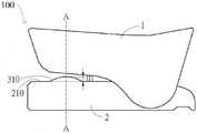
图1A为本申请第一实施例的生物讯息量测装置的侧视示意图。FIG. 1A is a schematic side view of a biological information measuring device according to a first embodiment of the present application.
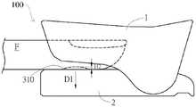
图1B为图1A的生物讯息量测装置的实施示意图。FIG. 1B is a schematic diagram of the implementation of the biological information measurement device of FIG. 1A .
图2为图1A的生物讯息量测装置的透视示意图,但处于开启位置。FIG. 2 is a schematic perspective view of the biological information measuring device of FIG. 1A , but in an open position.
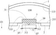
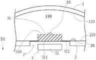
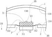
图3A和图3B为图1的生物讯息量测装置沿剖线A-A的横截面图,分别用于机电的换能器组件和光学换能器组件。3A and 3B are cross-sectional views of the bio-information measuring device of FIG. 1 taken along the line A-A, which are used for an electromechanical transducer assembly and an optical transducer assembly, respectively.
图4A和4B为图3A和图3B的换能器组件的手指接触面用于承受各个组件的外力。Figures 4A and 4B illustrate that the finger contact surfaces of the transducer assemblies of Figures 3A and 3B are used to withstand the external forces of the respective assemblies.
图5为图3A和图3B的变化实施例,其中接触件有一罩子。FIG. 5 is a modified embodiment of FIGS. 3A and 3B, wherein the contact piece has a cover.
图6为图1的生物讯息量测装置的变化实施例示意图。FIG. 6 is a schematic diagram of a modified embodiment of the biological information measuring apparatus of FIG. 1 .
图7为图1的生物讯息量测装置的爆炸示意图。FIG. 7 is an exploded schematic diagram of the biological information measuring device of FIG. 1 .
图8A为图6的生物讯息量测装置的实施示意图。FIG. 8A is a schematic diagram of the implementation of the biological information measurement device of FIG. 6 .
图8B为图6的生物讯息量测装置的另一实施示意图。FIG. 8B is a schematic diagram of another implementation of the biological information measurement device of FIG. 6 .
图9为图1的生物讯息量测装置的另一变化实施例示意图。FIG. 9 is a schematic diagram of another variant embodiment of the biological information measuring apparatus of FIG. 1 .
图10A为图9的生物讯息量测装置的实施示意图。FIG. 10A is a schematic diagram of the implementation of the biological information measurement device of FIG. 9 .
图10B为图9的生物讯息量测装置的另一实施示意图。FIG. 10B is a schematic diagram of another implementation of the biological information measuring device of FIG. 9 .
图11为本发明第二实施例的生物讯息量测装置的立体示意图。11 is a three-dimensional schematic diagram of a biological information measuring apparatus according to a second embodiment of the present invention.
图12为图11的生物讯息量测装置的实施示意图。FIG. 12 is a schematic diagram of the implementation of the biological information measuring device of FIG. 11 .
图13为图11的生物讯息量测装置的变化实施例示意图。FIG. 13 is a schematic diagram of a modified embodiment of the biological information measuring device of FIG. 11 .
具体实施方式Detailed ways
请参阅图1A为本申请第一变化实施例的生物讯息量测装置100包含第一构件1、第二构件2以及具有接触面的感测组件3。第一构件1具有第一内侧面,第二构件2具有第二内侧面210与第一内侧面相对。图2示出在开启位置时的生物讯息量测装置100以较佳地说明在生物讯息量测装置100中接收供测试的手指F的容置空间130。如图1B所示,其中手指F进入容置空间130并与第一内侧面110和第二内侧面210耦合。感测组件3的接触面设置于第二构件2的第二内侧面210上且具有手指接触面310与第一内侧面110相对。具体来说,容置空间130是用于容纳待测手指,并且换能器组件3的手指接触面310用以与手指的量测表面接触来接收生物讯息。实际来说,待测面通常为待测手指的指腹,但不以此为限。手指接触面310可在垂直于手指接触面310的第一方向D1来回移动。Referring to FIG. 1A , a biological
图1B为图1的生物讯息量测装置的实施示意图。当手指F插入由上方构件和下方构件的空间之间定义的容置空间,且手指F抵接于感测组件3的接触面310,接触面310由于承受手指施加的力而移动(一般在方向D)。结果,手指接触面310相对于第二内侧面210的高度由图1A中的H1降至图1B中的H2。传感器组件的接触面310沿方向Dl来回移动的能力得以使换能器组件(下文讨论)能够在相对较短的距离内接收来自手指F中血管更精确的生物讯息。FIG. 1B is a schematic diagram of the implementation of the biological information measuring device of FIG. 1 . When the finger F is inserted into the accommodating space defined by the space between the upper member and the lower member, and the finger F abuts on the
图2说明生物讯息量测装置100,其中上部构件1相对于下部构件2位在开启位置。图1A和图1B说明处于封闭配置的生物讯息量测装置100。如图2所示,作为接触件(未示出)的一部分或与之相邻的接触面310延伸到第二内侧面210之外,以使在关闭位置时,接触面310和接触件延伸到容置空间(也就是表面110和210之间的区域)。如图所示,上部构件1可通过任何常规方式与下部构件2可旋转地耦接,包括使用插销或轴6,关于在上部构件1围绕该插销或轴旋转从开放配置移动至封闭配置。FIG. 2 illustrates the
在此描述的生物讯息量测装置100可以包括任何数量的感测器组件。举例来说,当感测器组件是一个电子机械组件时,感测器组件包括一个压力感测器(如压电感测器),以及生物讯息包括血压讯息或脉搏讯息。然而,本申请中的生物讯息不限于血压讯息和脉搏讯息。在本申请的其他实施例中,换能器组件3可以包括压力感测器和光学感测器,以同时接收与血压、脉搏、葡萄糖浓度、心率和氧气饱和度等有关的讯息。The biological
现有的装置会对手指造成不适,用一个上盖和一个下盖来限制手指的同时,用一个感测器突出至手指腹中。在本申请揭示的装置中,由于接触件/接触面可沿第一方向Dls移动,手指受到较小的压力下,因此施加在手指上压力也减少。The existing device may cause discomfort to the fingers, and a sensor is used to protrude into the abdomen of the fingers while an upper cover and a lower cover are used to restrain the fingers. In the device disclosed in the present application, since the contact piece/contact surface can move along the first direction Dls, the finger is under less pressure, so the pressure exerted on the finger is also reduced.
图3A和图3B表示出图1的生物讯息量测装置沿剖线AA的横截面图,分别用于机电的换能器组件(图3A)和光学换能器组件(图3B)。为了展示本申请的概念,感测器没有说明电极或其他电路,这些对于本领域的技术人员来说是显而易见的。如图所示,感测器组件3的变化例可以包括一接触件31和至少一感测器元件32。在机电感测器(如压电组件)的情况下,感测器元件32被固定在装置内(由锚37表示),并与驱动器或其他机械部件39相邻,该部件将接触件31的动态传递给感测器元件32。在图3B所示的变化例中,光学组件3可以包括任意数量的照明光源35,这些照明光源可选择性地设置在接触件31和/或第二构件2上。照明光源35可以是LED、光纤或其他照明来源,像是自手指产生的反射能量而通过接触件31并传输到感测器元件32。在图3B所示的变化中,感测器元件32可以固定在接触件31上(并相对于第二构件2自由浮动),也可以固定在第二构件2上。3A and 3B show cross-sectional views of the bio-information measuring device of FIG. 1 taken along line AA, for an electromechanical transducer assembly (FIG. 3A) and an optical transducer assembly (FIG. 3B), respectively. In order to demonstrate the concepts of the present application, the sensor does not illustrate electrodes or other circuits that will be apparent to those skilled in the art. As shown, variations of the
接触件31位于感测器元件32与容置空间130之间。如上所述,接触件31可沿方向D1移动,以使感测组件3可沿方向D1来回移动,接触件31与第二构件2连接,并通过一个连接区域偏转以使接触件31的移动。图4A和4B描绘出图3A和图3B的感测组件的接触表面310受到一个外力El。如图4A所示,接触件31的移位导致驱动器或机械件39朝感测器32移动,导致所示的感测器32的位移。该组件3能将位移传输成一个可转换成确定生物讯息的信号。实际上,接触件31靠着感测器32的移动并未区分来自手指运动的力和由手指中血液循环的流动所引起的力。然而,这些移动可以通过信号处理加以区分。例如,脉动流通常是周期性的,但手指运动是随机的。此外,当手指的脉动血流引起接触件31的移动而导致感测器变形,由手指推压接触件31引起的初始位移相对于小的位移会造成很大的位移。相较之下,在图4B的光学组件中,只要感测器元件32不妨碍接触件31的移动,感测器元件32可以机械式地耦合到接触件31上,或是可以独立固定于接触件31。在光学感测组件的另一种变化例中,感测器元件32可以用来限制接触件31的移动。The
第二内侧面210具有开口P,接触件31被悬挂在其中。感测器元件32也可以设置于开口P中,且较第二内侧面210远离容置空间130。接触件31也能形成感测组件3的中央区域311,其中连接区域312将接触件31连接至开口P的边缘。除此之外,连接区域312可沿在第一方向Dl上弹性地变形。连接区域312可沿第一方向D1弹性地产生变形。在装置的变化例中,由于接触件31的存在,中央区域311比连接区域312硬,以使施加于中央区域311的外力E1可部分地传递至连接区域312。通过上述结构特征,当从容置空间130施加一沿着第一方向D1的外力E1给中央区域311时,部分外力E1将通过中央区域311传递至连接区域312,导致连接区域312沿第一方向D1产生变形。结果显示,中央区域311将移动至开口R后,从而将外力El的压力讯息传输至感测器元件32。The second
本申请不限于图3和图4说明的变化例。本申请装置的其他变化包括设置在弹性接触件31内的感测器元件32,感测器元件32能与弹性接触件31沿第一方向Dl朝开口P移动。图5说明了具有弹性膜33的感测组件3的变化例,弹性膜33形成组织接触面310并覆盖于接触件31以及连接容置空间130,以提升手指与手指接触面310接触的舒适度。The present application is not limited to the variations illustrated in FIGS. 3 and 4 . Other variations of the device of the present application include the
请参阅图6,说明本申请的生物讯息量测装置100的一个变化例。在此变化例中,生物讯息量测装置100的第一构件1和第二构件2与弹簧4及作为定位件的轴或销5。因此,第一构件1与第二构件2可以相对弹簧4的中心枢转而开启或闭合。明确来说,弹簧4具有可相对被拉伸的弹簧第一端401以及弹簧第二端402。弹簧第一端401连接于第一构件1,和弹簧第二端402连接于第二构件2。部分的第一构件1与部分的第二构件2共同形成限位槽G。定位件5设置于限位槽G内。由于限位槽G系由部分的第一构件1与部分的第二构件2共同形成,因此定位件5具有限制第一构件1与第二构件2相对位置的效果。Please refer to FIG. 6 , which illustrates a variation of the biological
进一步来说,本申请的限位槽G可通过图7以分解图的方式来说明。为方便示意限位槽G的结构,图7仅图示第一构件1、第二构件2以及限位槽G。容置空间130具有手指伸入方向Din以及与第一方向D1及手指伸入方向Din正交的第二方向D2。第一构件1具有沿第二方向D2的两个朝向彼此的侧槽G1,第二构件2具有沿第二方向D2的穿孔G2。当第一构件1与第二构件2以侧槽G1对应穿孔G2的方式组装时,侧槽G1及穿孔G2共同形成限位槽G,至少部分定位件5沿第二方向D2延伸进入侧槽G1与穿孔G2内以固定第一构件1与第二构件2的相对位置。本申请的限位槽G不限于图7所图示的组成方式,在其他变化例中,可以是第一构件1设有穿孔G2、第二构件2设有侧槽G1,且定位件5同时设置于第一构件1的穿孔G2与第二构件2的侧槽G1内延伸。Further, the limiting groove G of the present application can be illustrated in an exploded view with reference to FIG. 7 . For the convenience of illustrating the structure of the limiting groove G, FIG. 7 only illustrates the
请参阅图6说明图1的生物讯息量测装置U的一变化例,及图8A说明本申请的生物讯息量测装置U的应用。为了扩大生物讯息量测装置100的容置空间130,通过弹簧4与定位件5的设置,使用者可从装置U的外侧施加外力。例如,第一构件1的第一外侧面120朝第一方向D1施力于第一构件尾端101,以及从第二构件2的第二外侧面220朝第一方向D1的相反方向施力于第二构件尾端201。当容置空间130被扩大时,此时手指F可沿方向Din伸入容置空间130,如图8A说明。当手指F放置于换能器组件3上方,使用者可收回上述施力。结果显示,通过弹簧4的恢复力,弹簧4的第一端401与第二端402朝向彼此接近而使生物讯息量测装置100闭合。因此,将手指固定于第一构件1与第二构件2之间。Please refer to FIG. 6 to illustrate a modification of the biological information measuring device U of FIG. 1 , and FIG. 8A to illustrate the application of the biological information measuring device U of the present application. In order to expand the
此外,如图6所示,定位件5穿设于弹簧4的中心。因此,以使弹簧4与定位件5可以置换,且定位件5可在限位槽G内于第一方向D1来回移动。请参阅图8B,当沿第一方向D1厚度较粗的手指F置入容置空间130,手指F会顶起第一构件1而将第一构件1往第一方向D1的相反方向带领。由于弹簧4的第一端401连接于第一构件1,此时弹簧4的中心也会被带往第一方向D1的反方向移动。由于定位件5与弹簧4连动,定位件5也会在限位槽G内被弹簧4带往第一方向D1的反方向移动。当定位件5抵达限位槽G的顶端,如图8B所示,当定位件5到达限位槽G的顶部边缘时,其运动受到限制。即卡止于该处,弹簧4也无法再往第一方向D1的反方向移动。因此,当限位槽G对定位件5限位时,也连带对弹簧4及第一构件1形成卡止效果。In addition, as shown in FIG. 6 , the positioning
有了本申请上述特点,生物讯息量测装置100可容纳较大范围的手指粗度。相较于现有的指夹式量测装置,本申请的生物讯息量测装置100在容纳较厚的手指F时,亦能够维持第一构件1与测手指F有足够的接触面积,使手指F较稳固地被固定在容置空间130,由此降低感测噪声以提升量测的准确度,且提升手指F的舒适度。With the above features of the present application, the biological
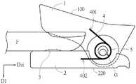
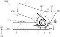
请参阅图9,说明本申请另一变化例的生物讯息量测装置100。像是生物讯息量测装置进一步包括限位轮缘6设置于第一构件1与第二构件2之间。第一构件1与第二构件2通过枢转组件相连接,且可相对枢转组件在最大开启位置以及最小闭合位置之间进行相对旋转。本实施例中,枢转组件如图6所示包括弹簧4、定位件5以及限位槽G,然而本发明不限于此。例如在其他实施例中,枢转组件也可是形状类似于图6的弹簧4但其两端分别朝向第一构件尾端101与第二构件尾端201。Please refer to FIG. 9 , which illustrates another modification of the biological
请参阅图9说明了生物讯息量测装置的另一种变化例,及图10A说明了一种本申请的装置的应用。图10A显示第一构件1与第二构件2位在最大开启位置时的示意图。限位轮缘6具有第一轮缘端部601在测试下位于枢转组件远离容置空间130的一侧。当第一构件尾端101受外力E2而使第一构件1与第二构件2相对旋转到最大开启位置。同时,限位轮缘6的第一轮缘端部601朝第二构件2移动,且当第一构件1和第二构件2达到最大开启位置时,如图10A所示,限位轮缘6的第一轮缘端部601接触到第二构件2的第二内侧面210。如此,限位轮缘6的第一轮缘端部601可阻止弹簧4进一步被撑开导致过度变形而影响其恢复力。Please refer to FIG. 9 to illustrate another variation of the biological information measuring device, and FIG. 10A to illustrate an application of the device of the present application. FIG. 10A shows a schematic diagram of the
请参阅图9说明了生物讯息量测装置的另一种变化例,以及图10B显示第一构件1与第二构件2位在最小闭合位置时的示意图。限位轮缘6具有第二轮缘端部602位于枢转组件靠近在测试下的容置空间130的一侧。当第一构件前端102受外力E3,而使第一构件1与第二构件2朝向最小闭合位置枢转。同时,限位轮缘6的第二轮缘端部602朝向第二构件2移动。且在第一构件1与第二构件2达到最小闭合位置时,如图10B所示,限位轮缘6的第二轮缘端部602接触于第二构件2的第二内侧面210。如此,限位轮缘6的第二轮缘端部602可阻止弹簧4进一步被压缩,限位轮缘端部601和602可以作为限位面来限制第一构件1对第二构件的相对移动。Please refer to FIG. 9 to illustrate another variation of the biological information measuring device, and FIG. 10B shows a schematic diagram when the
通过限位轮缘6的设置,本申请可避免弹簧4过度被拉伸或压缩,进而影响弹簧4的弹力,由此提升生物讯息量测装置100的使用时间。Through the setting of the limiting
综合上述,本发明第一实施例提供的生物讯息量测装置100通过手指沿垂直于接触面310的第一方向D1可来回移动的技术特征,以降低手指所受的压力。因此,在测量过程提升对手指量测时的舒适度。To sum up the above, the biological
此外,本实施例提供的弹簧4、定位件5以及限位槽G的相互限位机制可使生物讯息量测装置100适用于较大范围的手指粗度,且在手指粗度较粗时,第一构件与手指仍能有足够的接触面积,由此提升量测时的舒适度。并且,手指在生物讯息量测装置100中的夹持稳固程度能提高,进而得到较精确的量测数据。另一方面,本实施例通过限位轮缘6的设置,可防止弹簧4过度变形,延长生物讯息量测装置100的使用时间。In addition, the mutual limiting mechanism of the
本申请第二实施例的生物讯息量测装置The biological information measuring device according to the second embodiment of the present application
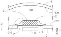
图11显示本申请第二实施例提供的生物讯息量测装置100。在本申请第二实施例中,与第一实施例的生物讯息量测装置100相同的元件以相同的标号表示。请参阅图12显示图11的生物讯息量测装置100的应用。第二实施例与第一实施例主要差异在于:第二实施例的生物讯息量测装置100的第一构件1具有透光组件11。具体来说,透光组件11于第二内侧面210上的投影范围与换能器组件3至少部份重叠。此外,透光组件11贯穿第一构件1以允许至少光线传播通过第一构件1的第一内侧面110以及第一构件的第一外侧面120之间的第一构件1。具体来说,本实施例透光组件11可让使用者将手指F置入容置空间130时,可从第一构件1的第一外侧面120观察到手指F,如图12所示。由此本实施例可提升手指F与换能器组件3精确对准,以进一步提升量测效率和准确性。透光组件11可以包括一种光学上透明或光学上不透明的材料以允许光线通过观察。或者,透光组件11可以包括一个或多个开口以允许在开口不影响装置容纳手指的情况下观察。FIG. 11 shows the biological
请参阅图13说明为图11的生物讯息量测装置100的一变化例。透光组件11可包括贯穿第一构件1本体的透明盖111以及直接连接于透明盖111且设置于透明盖111与容置空间130之间的透明软垫112。透明软垫112可例如由硅胶、乳胶、PU泡棉等软性材料制成,以将第一构件1与第二构件2朝容置空间130夹压的力量均匀分散至整个透明软垫112与手指F的接触范围。因此,由此提升手指F的舒适度。在本变化实施例中,透明软垫112在用以接触手指的一侧具有凹面1120与容置空间130对接,以增加与手指的贴合程度。结果,由此提升生物讯息量测装置100中夹置手指的稳定性。因此,可以降低感测噪声并提升量测精准度。Please refer to FIG. 13 to illustrate a modification of the biological
尽管本申请已参照其优选实施方案进行了描述,但应理解本申请不限于其细节。根据本申请的适当技术方案和技术概念进行的各种改变和修改应属于本申请的权利要求。因此,所有这些替换和修改都是为了包含在所附权利要求书中定义的本发明的范围内。While the application has been described with reference to preferred embodiments thereof, it is to be understood that the application is not limited to its details. Various changes and modifications according to the appropriate technical solutions and technical concepts of the present application shall belong to the claims of the present application. Accordingly, all such alternatives and modifications are intended to be included within the scope of the present invention as defined in the appended claims.
在已知的结构、材料或操作没有详细显示或描述,以避免掩盖所述装置的各个方面。正如本领域的技术人员所能理解的,所描述的实施例可以以各种不同的方式进行修改,所有这些都不会背离本发明的精神或范围。应该注意的是,在没有冲突的情况下,在本发明的实施例中,和实施例中的特征可以相互结合。因此,应该理解的是,这里描述的实施方案并不打算穷尽根据本公开的所有可能的实施方案,而且可以根据这里公开的主题构想出额外的实施方案。Well-known structures, materials, or operations have not been shown or described in detail to avoid obscuring aspects of the device. As those skilled in the art would realize, the described embodiments may be modified in various different ways, all without departing from the spirit or scope of the present invention. It should be noted that in the embodiments of the present invention, and features of the embodiments may be combined with each other without conflict. Therefore, it should be understood that the embodiments described herein are not intended to be exhaustive of all possible embodiments in accordance with the present disclosure and that additional embodiments may be contemplated in light of the subject matter disclosed herein.
Claims (33)
Applications Claiming Priority (3)
| Application Number | Priority Date | Filing Date | Title |
|---|---|---|---|
| US201962879536P | 2019-07-29 | 2019-07-29 | |
| US62/879,536 | 2019-07-29 | ||
| PCT/US2020/044085WO2021021941A1 (en) | 2019-07-29 | 2020-07-29 | Bioinformation measuring device |
Publications (2)
| Publication Number | Publication Date |
|---|---|
| CN114364309Atrue CN114364309A (en) | 2022-04-15 |
| CN114364309B CN114364309B (en) | 2024-08-06 |
Family
ID=74230836
Family Applications (1)
| Application Number | Title | Priority Date | Filing Date |
|---|---|---|---|
| CN202080054793.9AActiveCN114364309B (en) | 2019-07-29 | 2020-07-29 | Biological information measuring device |
Country Status (7)
| Country | Link |
|---|---|
| US (1) | US20220096013A1 (en) |
| EP (1) | EP4003157A4 (en) |
| JP (1) | JP7557524B2 (en) |
| CN (1) | CN114364309B (en) |
| AU (1) | AU2020321902B2 (en) |
| TW (1) | TWI829953B (en) |
| WO (1) | WO2021021941A1 (en) |
Cited By (1)
| Publication number | Priority date | Publication date | Assignee | Title |
|---|---|---|---|---|
| WO2025011487A1 (en)* | 2023-07-07 | 2025-01-16 | 台医光电科技股份有限公司 | Photoplethysmography measurement apparatus and optical blood pressure measurement apparatus |
Citations (11)
| Publication number | Priority date | Publication date | Assignee | Title |
|---|---|---|---|---|
| GB823954A (en)* | 1955-04-22 | 1959-11-18 | Juenkerather Gewerkschaft | Oscillator |
| US4685464A (en)* | 1985-07-05 | 1987-08-11 | Nellcor Incorporated | Durable sensor for detecting optical pulses |
| US5413099A (en)* | 1992-05-15 | 1995-05-09 | Hewlett-Packard Company | Medical sensor |
| US20020156354A1 (en)* | 2001-04-20 | 2002-10-24 | Larson Eric Russell | Pulse oximetry sensor with improved spring |
| CN101257839A (en)* | 2005-08-08 | 2008-09-03 | 内尔科尔普里坦贝内特公司 | Medical sensor and technique for using the same |
| CN101411618A (en)* | 2007-10-17 | 2009-04-22 | 潘卫江 | Finger type instrument for detecting sphygmus and blood oxygen saturation |
| US20100317936A1 (en)* | 2009-05-19 | 2010-12-16 | Masimo Corporation | Disposable components for reusable physiological sensor |
| US20170055854A1 (en)* | 2015-08-28 | 2017-03-02 | Maged Choucair | Non-invasive cardiovascular monitoring device |
| WO2017208645A1 (en)* | 2016-05-31 | 2017-12-07 | 国立大学法人九州大学 | Flow volume measuring device, flow volume measuring method, pressure measuring device, and pressure measuring method |
| CN208573729U (en)* | 2017-12-08 | 2019-03-05 | 杭州兆观传感科技有限公司 | A kind of finger ring type pulse blood oxygen instrument |
| CN208740983U (en)* | 2018-01-31 | 2019-04-16 | 博邦芳舟医疗科技(北京)有限公司 | Physiological indication detector probe |
Family Cites Families (8)
| Publication number | Priority date | Publication date | Assignee | Title |
|---|---|---|---|---|
| US5511546A (en) | 1993-09-20 | 1996-04-30 | Hon; Edward H. | Finger apparatus for measuring continuous cutaneous blood pressure and electrocardiogram electrode |
| US5438986A (en)* | 1993-12-14 | 1995-08-08 | Criticare Systems, Inc. | Optical sensor |
| CA2516556A1 (en)* | 2003-03-06 | 2004-09-23 | Applied Medical Resources Corporation | Spring clip and method for assembling same |
| US8073518B2 (en)* | 2006-05-02 | 2011-12-06 | Nellcor Puritan Bennett Llc | Clip-style medical sensor and technique for using the same |
| US8515509B2 (en)* | 2008-08-04 | 2013-08-20 | Cercacor Laboratories, Inc. | Multi-stream emitter for noninvasive measurement of blood constituents |
| US9603559B2 (en)* | 2009-12-24 | 2017-03-28 | Children's Medical Center Corporation | Capillary refill time diagnostic apparatus and methods |
| US9743867B2 (en)* | 2010-02-24 | 2017-08-29 | Takahiro Fujii | Pulse oximeter |
| US20130096405A1 (en)* | 2011-08-12 | 2013-04-18 | Masimo Corporation | Fingertip pulse oximeter |
- 2020
- 2020-07-28TWTW109125426Apatent/TWI829953B/enactive
- 2020-07-29JPJP2022504155Apatent/JP7557524B2/enactiveActive
- 2020-07-29WOPCT/US2020/044085patent/WO2021021941A1/ennot_activeCeased
- 2020-07-29EPEP20846605.2Apatent/EP4003157A4/enactivePending
- 2020-07-29CNCN202080054793.9Apatent/CN114364309B/enactiveActive
- 2020-07-29AUAU2020321902Apatent/AU2020321902B2/enactiveActive
- 2021
- 2021-12-06USUS17/543,397patent/US20220096013A1/enactivePending
Patent Citations (12)
| Publication number | Priority date | Publication date | Assignee | Title |
|---|---|---|---|---|
| GB823954A (en)* | 1955-04-22 | 1959-11-18 | Juenkerather Gewerkschaft | Oscillator |
| US2955476A (en)* | 1955-04-22 | 1960-10-11 | Junkerather Gewerkschaft | Vibrators |
| US4685464A (en)* | 1985-07-05 | 1987-08-11 | Nellcor Incorporated | Durable sensor for detecting optical pulses |
| US5413099A (en)* | 1992-05-15 | 1995-05-09 | Hewlett-Packard Company | Medical sensor |
| US20020156354A1 (en)* | 2001-04-20 | 2002-10-24 | Larson Eric Russell | Pulse oximetry sensor with improved spring |
| CN101257839A (en)* | 2005-08-08 | 2008-09-03 | 内尔科尔普里坦贝内特公司 | Medical sensor and technique for using the same |
| CN101411618A (en)* | 2007-10-17 | 2009-04-22 | 潘卫江 | Finger type instrument for detecting sphygmus and blood oxygen saturation |
| US20100317936A1 (en)* | 2009-05-19 | 2010-12-16 | Masimo Corporation | Disposable components for reusable physiological sensor |
| US20170055854A1 (en)* | 2015-08-28 | 2017-03-02 | Maged Choucair | Non-invasive cardiovascular monitoring device |
| WO2017208645A1 (en)* | 2016-05-31 | 2017-12-07 | 国立大学法人九州大学 | Flow volume measuring device, flow volume measuring method, pressure measuring device, and pressure measuring method |
| CN208573729U (en)* | 2017-12-08 | 2019-03-05 | 杭州兆观传感科技有限公司 | A kind of finger ring type pulse blood oxygen instrument |
| CN208740983U (en)* | 2018-01-31 | 2019-04-16 | 博邦芳舟医疗科技(北京)有限公司 | Physiological indication detector probe |
Cited By (1)
| Publication number | Priority date | Publication date | Assignee | Title |
|---|---|---|---|---|
| WO2025011487A1 (en)* | 2023-07-07 | 2025-01-16 | 台医光电科技股份有限公司 | Photoplethysmography measurement apparatus and optical blood pressure measurement apparatus |
Also Published As
| Publication number | Publication date |
|---|---|
| JP2022542253A (en) | 2022-09-30 |
| CN114364309B (en) | 2024-08-06 |
| AU2020321902B2 (en) | 2025-04-03 |
| US20220096013A1 (en) | 2022-03-31 |
| TW202120013A (en) | 2021-06-01 |
| WO2021021941A1 (en) | 2021-02-04 |
| EP4003157A1 (en) | 2022-06-01 |
| AU2020321902A1 (en) | 2022-02-03 |
| EP4003157A4 (en) | 2023-08-30 |
| TWI829953B (en) | 2024-01-21 |
| JP7557524B2 (en) | 2024-09-27 |
Similar Documents
| Publication | Publication Date | Title |
|---|---|---|
| CN102438523B (en) | pulse oximeter | |
| US20250120656A1 (en) | Personal health data collection | |
| US11284822B1 (en) | Tissue oximeter intraoperative system | |
| US7742794B2 (en) | Probe adapted to be used with pulse oximeter | |
| US4685464A (en) | Durable sensor for detecting optical pulses | |
| JP6667321B2 (en) | Pulse oximeter probe | |
| JPS62142208A (en) | Optical motion sensor | |
| CN114364309B (en) | Biological information measuring device | |
| JP2007029702A (en) | Fingertip clip for photoelectric living body information measuring apparatus | |
| JP6667322B2 (en) | Pulse oximeter probe | |
| JP5401618B1 (en) | Pulse oximeter probe | |
| CN109414195B (en) | Device and method for measuring physiological parameters of a human limb | |
| JP7152756B2 (en) | Blood flow measuring device | |
| CN109414196B (en) | Device and method for measuring physiological parameters of a human limb | |
| CN113164051A (en) | Physiological measuring device and method thereof | |
| JP5054329B2 (en) | Subcutaneous fat thickness gauge | |
| JP2014100374A (en) | Non-invasive biological measurement instrument | |
| CN103533890A (en) | Analysis system having a measurement device and a testing element | |
| KR20220168659A (en) | Ear wearing type sensor probe for SpO2 measuring |
Legal Events
| Date | Code | Title | Description |
|---|---|---|---|
| PB01 | Publication | ||
| PB01 | Publication | ||
| SE01 | Entry into force of request for substantive examination | ||
| SE01 | Entry into force of request for substantive examination | ||
| GR01 | Patent grant | ||
| GR01 | Patent grant |