CN114362384A - Strong suction magnetic suction wireless charging device and magnetic suction wireless charging control method - Google Patents
Strong suction magnetic suction wireless charging device and magnetic suction wireless charging control methodDownload PDFInfo
- Publication number
- CN114362384A CN114362384ACN202210043764.3ACN202210043764ACN114362384ACN 114362384 ACN114362384 ACN 114362384ACN 202210043764 ACN202210043764 ACN 202210043764ACN 114362384 ACN114362384 ACN 114362384A
- Authority
- CN
- China
- Prior art keywords
- wireless charging
- module
- magnetic
- electromagnet
- strong
- Prior art date
- Legal status (The legal status is an assumption and is not a legal conclusion. Google has not performed a legal analysis and makes no representation as to the accuracy of the status listed.)
- Pending
Links
Images


Landscapes
- Charge And Discharge Circuits For Batteries Or The Like (AREA)
Abstract
Translated fromChinese
Description
Translated fromChinese技术领域technical field
本发明属于无线充电技术领域,特别涉及一种强吸力磁吸无线充电设备及磁吸无线充电控制方法。The invention belongs to the technical field of wireless charging, and in particular relates to a strong suction magnetic suction wireless charging device and a magnetic suction wireless charging control method.
背景技术Background technique
车载无线充的手机固定有两种方法,磁吸式固定和夹子式固定。前者依靠磁铁吸力实现手机固定,后者依靠夹子夹住手机,保证手机不掉落。前者优点是,方便,即放既吸,线圈对位准,充电效率高;缺点是吸力小;后者优点是夹的紧,但是会导致手机和无线充电有间隙,导致充电效率低。There are two ways to fix the mobile phone of the car wireless charger, magnetic fixation and clip fixation. The former relies on magnet suction to fix the mobile phone, while the latter relies on clips to hold the mobile phone to ensure that the mobile phone does not fall. The advantage of the former is that it is convenient, that is, it can be released and sucked, the coil is aligned, and the charging efficiency is high.
现有磁吸无线充产品,都是使用钕铁硼材料的磁铁。无线充能量发射器的线圈外围有一圈磁铁。手机内部的线圈外围也有一圈磁铁。磁铁的N极和S极通过磁力使无线充能量发射器和手机吸在一起。无线充能量发射器和手机内部磁铁的排布,如图1所示,由38块小磁铁构成磁环,手机内和无线充能量发射器均是相同的磁环,仅磁铁极性不同。磁铁极性如图2所示,无线充能量发射器的磁铁01上表面的N极和手机内部的磁铁02的S极相吸,无线充能量发射器的磁铁01上表面的S极和手机内部磁铁02的N极相吸,实现无线充能量发射器和手机相吸。The existing magnetic suction wireless charging products are all magnets using NdFeB materials. There is a circle of magnets around the coil of the wireless charging energy transmitter. There is also a ring of magnets around the coil inside the phone. The N pole and S pole of the magnet make the wireless charging energy transmitter and the mobile phone attract together by magnetic force. The arrangement of the wireless charging energy transmitter and the internal magnets of the mobile phone, as shown in Figure 1, consists of 38 small magnets to form a magnetic ring. Both the mobile phone and the wireless charging energy transmitter are the same magnetic ring, only the polarity of the magnets is different. The polarity of the magnet is shown in Figure 2. The N pole on the upper surface of the
然而,无线充能量发射器的吸力通常不强,汽车颠簸时会导致手机等待充电装置跌落。该磁铁为充磁磁铁,其自身吸力由材料、尺寸决定,受到手机尺寸限制和量产的材料限制,吸力无法进一步提升。However, the suction power of the wireless charging transmitter is usually not strong, and the bumping of the car can cause the phone to fall while waiting for the charging unit. The magnet is a magnetized magnet, and its suction force is determined by the material and size. Due to the limitation of the size of the mobile phone and the material limitation of mass production, the suction force cannot be further improved.
因此,如何提高磁吸无线充电设备的磁吸力,是本领域技术人员亟待解决的问题。Therefore, how to improve the magnetic attraction force of the magnetic attraction wireless charging device is an urgent problem to be solved by those skilled in the art.
发明内容SUMMARY OF THE INVENTION
本发明的目的在于提供一种强吸力磁吸无线充电设备及及磁吸无线充电控制方法,可提高磁吸无线充电设备的磁吸力。The purpose of the present invention is to provide a strong suction magnetic suction wireless charging device and a magnetic suction wireless charging control method, which can improve the magnetic attraction force of the magnetic suction wireless charging device.
为解决上述技术问题,本发明提供一种强吸力磁吸无线充电设备,包括壳体,以及设置于所述壳体的电源输入模块、无线充电模块、降压模块、无线充控制器和电磁铁;In order to solve the above technical problems, the present invention provides a strong suction magnetic wireless charging device, including a casing, and a power input module, a wireless charging module, a step-down module, a wireless charging controller and an electromagnet arranged on the casing. ;
所述电源输入模块用于对所述无线充电模块和所述降压模块供电;The power input module is used to supply power to the wireless charging module and the step-down module;
所述无线充电模块用于对待充电装置无线充电;The wireless charging module is used for wirelessly charging the device to be charged;
所述压降模块用于对所述电磁铁供电,以使输入电压转化为所述电磁铁的供电电压;The voltage drop module is used for supplying power to the electromagnet, so that the input voltage is converted into the power supply voltage of the electromagnet;
所述无线充控制器用于判断是否开启所述电源输入模块分别与所述无线充电模块和所述降压模块之间的连通,以及控制所述无线充电模块和所述降压模块的电流大小。The wireless charging controller is used for judging whether to open the communication between the power input module and the wireless charging module and the step-down module respectively, and to control the current size of the wireless charging module and the step-down module.
可选的,还包括充磁磁铁组件,Optionally, it also includes a magnetizing magnet assembly,
所述电磁铁的N级通过第一导磁片连接所述充磁磁铁组件的N级,The N stage of the electromagnet is connected to the N stage of the magnetizing magnet assembly through the first magnetic conductive sheet,
所述电磁铁的S级通过第二导磁片连接所述充磁磁铁组件的S级。The S stage of the electromagnet is connected to the S stage of the magnetizing magnet assembly through a second magnetic conductive sheet.
可选的,所述充磁磁铁组件包括多个串联布置的充磁磁铁,多个所述充磁磁铁和所述电磁铁共同围成一个环形。Optionally, the magnetizing magnet assembly includes a plurality of magnetizing magnets arranged in series, and the multiple magnetizing magnets and the electromagnets together form a ring.
可选的,所述第一导磁片和所述第二导磁片均为开口环,所述开口环的一端连接所述电磁铁的一端磁极且另一端连接所述充磁磁铁组件中位于首尾部分的充磁磁铁的相应磁极。Optionally, the first magnetic conductive sheet and the second magnetic conductive sheet are both split rings, one end of the split ring is connected to the magnetic pole of one end of the electromagnet, and the other end is connected to the magnetic pole located in the magnetizing magnet assembly. The corresponding poles of the magnetizing magnets in the head and tail sections.
可选的,所述开口环的一端开设有通孔,所述电磁铁的端部设置有用于与所述通孔对接的螺纹孔,所述开口环与所述电磁铁通过螺栓连接。Optionally, one end of the split ring is provided with a through hole, an end of the electromagnet is provided with a threaded hole for docking with the through hole, and the split ring and the electromagnet are connected by bolts.
可选的,,还包括电磁铁开关模块,所述无线充控制器还用于通过所述电磁铁开关模块的状态控制所述电磁铁通断。Optionally, an electromagnet switch module is further included, and the wireless charging controller is further configured to control the on-off of the electromagnet through the state of the electromagnet switch module.
可选的,所述电磁铁开关模块包括用于通过红外线实现人体感知的人体感应开关,Optionally, the electromagnet switch module includes a human body induction switch for realizing human body perception through infrared rays,
和/或,所述电磁铁开关模块包括手动开关。And/or, the electromagnet switch module includes a manual switch.
可选的,所述无线充电模块和所述降压模块并联设置于所述电源输入模块。Optionally, the wireless charging module and the step-down module are arranged in parallel with the power input module.
可选的,所述无线充控制器还用于根据待充电装置的输入功率而选择所述无线充电模块自身输出功率。Optionally, the wireless charging controller is further configured to select the output power of the wireless charging module itself according to the input power of the device to be charged.
本案还提供一种强吸力磁吸无线充电控制方法,应用上述的强吸力磁吸无线充电设备,所述方法包括:This case also provides a strong suction magnetic suction wireless charging control method, using the above strong suction magnetic suction wireless charging device, the method includes:
步骤S1、判断是否有待充电装置,若没有,则所述强吸力磁吸无线充电设备处于待机模式,若有,则进入下一步骤;Step S1, judging whether there is a device to be charged, if not, the strong suction magnetic wireless charging device is in standby mode, if there is, then go to the next step;
步骤S2、开启所述无线充电模块;Step S2, turning on the wireless charging module;
步骤S3、开启所述压降模块;Step S3, turning on the pressure drop module;
步骤S4、判断所述电磁铁开关模块的状态,若为关闭,则保持上述状态,若为开启,则关闭所述压降模块;Step S4, judging the state of the electromagnet switch module, if it is off, keep the above state, and if it is on, turn off the voltage drop module;
步骤S5、关闭所述无线充电模块。Step S5, turning off the wireless charging module.
本发明所提供的一种强吸力磁吸无线充电设备,其有益效果在于:The strong suction magnetic suction wireless charging device provided by the present invention has the beneficial effects of:
电源输入模块用于对无线充电模块和降压模块供电。无线充电模块用于对待充电装置无线充电。压降模块用于将输入电压转化为电磁铁的供电电压。无线充控制器用于控制电源输入模块是否对无线充电模块和降压模块供电,以及供电电压大小。采用电磁铁提供待充电装置的磁吸力,通过控制电磁铁电流,实现强吸力和吸力可控。The power input module is used to supply power to the wireless charging module and the step-down module. The wireless charging module is used for wirelessly charging the device to be charged. The voltage drop module is used to convert the input voltage to the supply voltage for the electromagnet. The wireless charging controller is used to control whether the power input module supplies power to the wireless charging module and the step-down module, as well as the power supply voltage. The electromagnet is used to provide the magnetic attraction force of the device to be charged, and by controlling the current of the electromagnet, the strong attraction force and the suction force are controllable.
本案还提供一种应用于上述强吸力磁吸无线充电设备的强吸力磁吸无线充电控制方法,有益效果同上,在此不在进一步赘述。The present application also provides a strong-attraction magnetic-absorption wireless charging control method applied to the above-mentioned strong-attraction magnetic-absorption wireless charging device, the beneficial effects are the same as above, and are not further described here.
附图说明Description of drawings
为了更清楚地说明本发明实施例或现有技术中的技术方案,下面将对实施例或现有技术描述中所需要使用的附图作简单地介绍,显而易见地,下面描述中的附图仅仅是本发明的实施例,对于本领域普通技术人员来讲,在不付出创造性劳动的前提下,还可以根据提供的附图获得其他的附图。In order to explain the embodiments of the present invention or the technical solutions in the prior art more clearly, the following briefly introduces the accompanying drawings that need to be used in the description of the embodiments or the prior art. Obviously, the accompanying drawings in the following description are only It is an embodiment of the present invention. For those of ordinary skill in the art, other drawings can also be obtained according to the provided drawings without creative work.
图1为现有技术提供的无线充能量发射器内线圈外围的磁铁的结构示意图;1 is a schematic structural diagram of a magnet around a coil in a wireless charging energy transmitter provided by the prior art;
图2为图1为现有技术提供的无线充能量发射器内磁铁极性的分布示意图;FIG. 2 is a schematic diagram of the distribution of the polarity of magnets in the wireless charging energy transmitter provided by FIG. 1 in the prior art;
图3为本发明提供的强吸力磁吸无线充电设备的电磁铁和充磁磁铁组合的结构简图;FIG. 3 is a schematic structural diagram of the combination of an electromagnet and a magnetizing magnet of the strong-attraction magnetic wireless charging device provided by the present invention;
图4为图3的结构拆解示意图;Fig. 4 is the structural dismantling schematic diagram of Fig. 3;
图5为图3的一种具体实施方式中的结构示意图;FIG. 5 is a schematic structural diagram in a specific embodiment of FIG. 3;
图6为本发明提供的强吸力磁吸无线充电设备内电磁铁极性的分布示意图;6 is a schematic diagram of the distribution of the polarities of electromagnets in the strong magnetic attraction wireless charging device provided by the present invention;
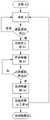
图7为本发明提供的强吸力磁吸无线充电设备的工作流程图;Fig. 7 is the working flow chart of the strong suction magnetic suction wireless charging device provided by the present invention;
图8为本发明提供的强吸力磁吸无线充电设备的系统框图。FIG. 8 is a system block diagram of the strong magnetic attraction wireless charging device provided by the present invention.
上图中:In the picture above:
现有技术中:01-无线充能量发射器的充磁磁铁;02-手机的磁铁;In the prior art: 01-magnetizing magnet of wireless charging energy transmitter; 02-magnet of mobile phone;
本申请中:100-强吸力磁吸无线充电设备的磁铁组件;110-电磁铁;111-铁芯;112-导电绕组;113-第一导磁片/第二导磁片;120-充磁磁铁组件;In this application: 100-magnet assembly of strong magnetic attraction wireless charging device; 110-electromagnet; 111-iron core; 112-conductive winding; 113-first magnetic conductive sheet/second magnetic conductive sheet; 120-magnetization magnet assembly;
200-电源输入模块;300-无线充电模块;400-降压模块;500-人体感应开关;600-线圈。200- power input module; 300- wireless charging module; 400- step-down module; 500- human body induction switch; 600- coil.
具体实施方式Detailed ways
下面详细描述本发明的实施例,所述实施例的示例在附图中示出,其中自始至终相同或类似的标号表示相同或类似的元件或具有相同或类似功能的元件。下面通过参考附图描述的实施例是示例性的,仅用于解释本发明,而不能理解为对本发明的限制。The following describes in detail the embodiments of the present invention, examples of which are illustrated in the accompanying drawings, wherein the same or similar reference numerals refer to the same or similar elements or elements having the same or similar functions throughout. The embodiments described below with reference to the accompanying drawings are exemplary, only used to explain the present invention, and should not be construed as a limitation of the present invention.
在本发明的描述中,需要理解的是,涉及到方位描述,例如上、下、前、后、左、右等指示的方位或位置关系为基于附图所示的方位或位置关系,仅是为了便于描述本发明和简化描述,而不是指示或暗示所指的装置或元件必须具有特定的方位、以特定的方位构造和操作,因此不能理解为对本发明的限制。In the description of the present invention, it should be understood that the azimuth description, such as the azimuth or position relationship indicated by up, down, front, rear, left, right, etc., is based on the azimuth or position relationship shown in the drawings, only In order to facilitate the description of the present invention and simplify the description, it is not indicated or implied that the indicated device or element must have a particular orientation, be constructed and operated in a particular orientation, and therefore should not be construed as limiting the present invention.
在本发明的描述中,多个的含义是两个以上,如果有描述到第一、第二只是用于区分技术特征为目的,而不能理解为指示或暗示相对重要性或者隐含指明所指示的技术特征的数量或者隐含指明所指示的技术特征的先后关系。In the description of the present invention, the meaning of multiple is more than two. If there is a description of the first and the second, it is only for the purpose of distinguishing technical features, and should not be understood as indicating or implying relative importance or implicitly indicating that The number of technical features indicated or implicitly indicates the order of the indicated technical features.
本发明的描述中,除非另有明确的限定,设置、安装、连接等词语应做广义理解,所属技术领域技术人员可以结合技术方案的具体内容合理确定上述词语在本发明中的具体含义。In the description of the present invention, unless otherwise clearly defined, words such as setting, installation, connection should be understood in a broad sense, and those skilled in the art can reasonably determine the specific meaning of the above words in the present invention in combination with the specific content of the technical solution.
本发明的核心是提供一种强吸力磁吸无线充电设备及磁吸无线充电控制方法,可提高磁吸无线充电设备的磁吸力。The core of the present invention is to provide a strong suction magnetic suction wireless charging device and a magnetic suction wireless charging control method, which can improve the magnetic attraction force of the magnetic suction wireless charging device.
为了使本领域的技术人员更好地理解本发明提供的技术方案,下面将结合附图和具体实施例对本发明作进一步的详细说明。In order to make those skilled in the art better understand the technical solutions provided by the present invention, the present invention will be further described in detail below with reference to the accompanying drawings and specific embodiments.
具体请参考图3-图8,图3为本发明提供的强吸力磁吸无线充电设备的电磁铁和充磁磁铁组合的结构简图;图4为图3的结构拆解示意图;图5为图3的一种具体实施方式中的结构示意图;图6为本发明提供的强吸力磁吸无线充电设备内电磁铁极性的分布示意图;图7为本发明提供的强吸力磁吸无线充电设备的工作流程图;图8为本发明提供的强吸力磁吸无线充电设备的系统框图。For details, please refer to FIGS. 3 to 8 . FIG. 3 is a schematic structural diagram of the combination of an electromagnet and a magnetizing magnet of a strong magnetic attraction wireless charging device provided by the present invention; FIG. 4 is a schematic diagram of disassembly of the structure of FIG. 3 ; FIG. 3 is a schematic structural diagram of a specific implementation manner; FIG. 6 is a schematic diagram of the distribution of the polarity of electromagnets in a strong-attraction magnetic wireless charging device provided by the present invention; FIG. 7 is a strong-attraction magnetic wireless charging device provided by the present invention. Figure 8 is a system block diagram of the strong magnetic magnetic wireless charging device provided by the present invention.
本发明提供了一种强吸力磁吸无线充电设备,包括壳体,以及设置于壳体的电源输入模块200、无线充电模块300、降压模块400、无线充控制器和电磁铁110。The present invention provides a strong suction magnetic wireless charging device, comprising a casing, a
其中,电源输入模块200用于对无线充电模块300和降压模块400供电。The
无线充电模块300用于对待充电装置无线充电。无线充电模块300的电压可根据当前待充电装置所需要的功率,而计算需要提供多大的电压/电流,即可调整线圈600的输出电压。无线充电模块300可采用现有技术中的无线充电技术,在此不再进一步赘述。The wireless charging module 300 is used for wirelessly charging the device to be charged. The voltage of the wireless charging module 300 can be calculated according to the current power required by the device to be charged, and how much voltage/current needs to be provided, so that the output voltage of the coil 600 can be adjusted. The wireless charging module 300 may adopt the wireless charging technology in the prior art, which will not be further described herein.
压降模块用于对电磁铁110供电,以使输入电压转化为电磁铁110的供电电压。其内部具有降压电路,以及电磁开关阀。降压电路可采用现有技术中的电路元件,在此不再进一步赘述。The voltage drop module is used to supply power to the
无线充控制器用于判断是否开启电源输入模块200分别与无线充电模块300和降压模块400之间的连通,以控制电源输入模块200是否对无线充电模块300和降压模块400供电,以及,以及控制无线充电模块300和降压模块400的供电电流/电压大小。The wireless charging controller is used to determine whether to open the communication between the
进一步地,所述无线充控制器还用于根据待充电装置的输入功率而选择所述无线充电模块300自身输出功率。Further, the wireless charging controller is further configured to select the output power of the wireless charging module 300 itself according to the input power of the device to be charged.
当然,在下文的实施方式中,无线充控制器可用于实现能量传输和各种控制功能,具体控制功能详见下文。Of course, in the following embodiments, the wireless charging controller can be used to realize energy transmission and various control functions, and the specific control functions are detailed below.
需要说明的是,电磁铁110是通电产生电磁的一种装置。如图4和图5所示,电磁铁110是由绕在铁芯111(不锈钢柱)的金属线圈构成,电磁铁110的供电由无线充电设备的降压模块400提供。在铁芯111的外部缠绕与其功率相匹配的导电绕组112,这种通有电流的线圈像磁铁一样具有磁性。电磁铁110通电时,有磁性;断电时,磁性消失。通过控制电磁铁110的电流,可以控制吸力大小。It should be noted that the
本案提供的一种强吸力磁吸无线充电设备,采用电磁铁110提供待充电装置的磁吸力,通过控制电磁铁110电流,实现强吸力和吸力可控。The present application provides a strong suction magnetic wireless charging device, which uses an
为了使待充电装置与强吸力磁吸无线充电设备对接时即具有一定吸力,方便对接,本案还包括充磁磁铁组件120,即永磁铁。In order to make the device to be charged have a certain suction force when it is docked with the strong attraction magnetic wireless charging device, so as to facilitate docking, the present case also includes a magnetizing
电磁铁110的N级通过第一导磁片113连接充磁磁铁组件120的N级,电磁铁110的S级通过第二导磁片113连接充磁磁铁组件120的S级。The N stage of the
可知的是,第一导磁片和第二导磁片起到导磁作用。导磁片为可以导磁的金属高磁导率材料制成,具体可为低碳钢。It is known that the first magnetic conductive sheet and the second magnetic conductive sheet play a role of magnetic conductivity. The magnetic conductive sheet is made of a metal material with high magnetic permeability that can be magnetically conductive, and can specifically be low carbon steel.
从布置方式上,第一导磁片和第二导磁片可分别设置于充磁磁铁组件120的两端面上。In terms of arrangement, the first magnetic conductive sheet and the second magnetic conductive sheet can be respectively disposed on both end surfaces of the magnetizing
在具体实施例中,如图3所示,充磁磁铁组件120包括多个串联布置的充磁磁铁,多个充磁磁铁和电磁铁110共同围成一个环形,形成强吸力磁吸无线充电设备的磁铁组件100。其中,黑色部分表示电磁铁110。小部分采用电磁铁110、绝大部分采用充磁磁铁,电磁铁110用于增强磁吸力,充磁磁铁用于前期的对接吸附。In a specific embodiment, as shown in FIG. 3 , the magnetizing
具体地,充磁磁铁可为低碳钢等材质充磁而成。多个充磁磁铁可依次间隔设置于支架上,支架可为上述环形结构,当然,还可以根据实际应用适应性的选择其他形状和连接方式,在此不做进一步限定。Specifically, the magnetizing magnet may be magnetized from materials such as low carbon steel. A plurality of magnetizing magnets can be arranged on the bracket at intervals in sequence, and the bracket can be of the above-mentioned annular structure. Of course, other shapes and connection methods can also be selected according to practical application adaptability, which is not further limited here.
在具体实施例中,如图4所示,开口环的一端开设有通孔,电磁铁110的端部设置有用于与通孔对接的螺纹孔,开口环与电磁铁110通过螺栓连接,实现锁紧。开口环的中间段不与充磁磁铁组件连接,为了便于布置,可绕充磁磁铁组件外缘设置。In a specific embodiment, as shown in FIG. 4 , one end of the split ring is provided with a through hole, the end of the
本案还包括电磁铁开关模块,无线充控制器还用于通过电磁铁开关模块的状态控制电磁铁110通断。This case also includes an electromagnet switch module, and the wireless charging controller is also used to control the on-off of the
在进一步具体实施例中,在一种情况下,电磁铁开关模块包括用于通过红外线实现人体感知的人体感应开关500,人体感应开关500与无线充控制器信号连接。人体检测模块通过红外线实现人体感知,用于告知无线充控制器开通还是关断电磁铁110。In a further specific embodiment, in one case, the electromagnet switch module includes a human body induction switch 500 for realizing human body perception through infrared rays, and the human body induction switch 500 is signally connected to the wireless charging controller. The human body detection module realizes human body perception through infrared rays, and is used to inform the wireless charging controller to turn on or turn off the
当然,在另一种情况下,电磁铁开关模块还可以包括手动开关,则手动开关与无线充控制器电连接。Of course, in another case, the electromagnet switch module may further include a manual switch, and the manual switch is electrically connected to the wireless charging controller.
为了防止功能之间的影响,无线充电模块300和降压模块400并联设置于电源输入模块200。In order to prevent the influence between functions, the wireless charging module 300 and the step-down
系统框图如图8所示,电源输入模块200是给系统供电的,支持PD、QC等协议,输入电压由无线充控制器决定,自动选择最优工作电压并识别供电设备的供电能力。降压模块400将输入电压转化为电磁铁110供电电压,由无线充控制器控制通断电时间。人体检测模块通过红外线实现人体感知,用于告知无线充控制器开通还是关断电磁铁110。无线充控制器用于实现能量传输和各种控制功能。The system block diagram is shown in Figure 8. The
在一种具体实施方式中,本发明提供一种强吸力磁吸无线充电控制方法,该方法应用上文中的强吸力磁吸无线充电设备,具体包括:In a specific embodiment, the present invention provides a strong suction magnetic wireless charging control method, the method applies the strong suction magnetic wireless charging device above, and specifically includes:
步骤S1、判断是否有待充电装置,若没有,则强吸力磁吸无线充电设备处于待机模式,若有,则进入下一步骤;Step S1, judging whether there is a device to be charged, if not, the strong suction magnetic wireless charging device is in standby mode, if there is, then go to the next step;
步骤S2、开启无线充电模块300;Step S2, turning on the wireless charging module 300;
步骤S3、开启压降模块,即开启电磁铁110。In step S3, the voltage drop module is turned on, that is, the
步骤S4、判断电磁铁开关模块的状态,若为关闭,则保持上述状态,若为开启,则关闭压降模块;Step S4, judging the state of the electromagnet switch module, if it is off, keep the above state, if it is on, then turn off the voltage drop module;
步骤S5、关闭无线充电模块300。Step S5 , turning off the wireless charging module 300 .
此外,在步骤S1前,还包括步骤A1:对电源输入模块200上电,步骤A2:强吸力磁吸无线充电设备进入待机模式。In addition, before step S1, it also includes step A1: powering on the
在步骤S5之后,强吸力磁吸无线充电设备处于待机模式,直至步骤A3:关闭设备电源。After step S5, the strong magnetic attraction wireless charging device is in standby mode until step A3: turning off the power of the device.
如图7所示的工作过程,待充电装置以手机为例,无线充电设备上电后,无线充电模块300进入待机模式,不断检测是否有手机放在无线充电设备的磁极上,如果有手机放置,无线充电模块300开始工作,并进行能量传输,同时降压电路开始为电磁铁110供电,电磁铁110吸力增强。当用户想取下手机时,手碰触人体感应开关500,人体感应开关500开启,关闭电磁铁110,吸力降下来,人可以拿走手机,并关闭无线充功能,此时无线充电模块300重新进入检测状态,检测是否有手机放置。As shown in Fig. 7, the charging device takes a mobile phone as an example. After the wireless charging device is powered on, the wireless charging module 300 enters the standby mode and continuously detects whether a mobile phone is placed on the magnetic pole of the wireless charging device. , the wireless charging module 300 starts to work and performs energy transmission, and at the same time, the step-down circuit starts to supply power to the
上述磁吸无线充电控制方法,采用电磁铁110提供待充电装置的磁吸力,通过无线充控制器判断是否开启电源输入模块200分别与无线充电模块300和降压模块400之间的连通,以及通过降压模块400控制电磁铁110电流的大小,实现强吸力和吸力可控。The above-mentioned magnetic attraction wireless charging control method adopts the
本说明中各个实施例采用递进的方式描述,每个实施例重点说明的都是与其他实施例的不同之处,各个实施例之间相同相似部分互相参见即可。The various embodiments in this specification are described in a progressive manner, and each embodiment focuses on the differences from other embodiments, and the same and similar parts between the various embodiments may be referred to each other.
本文中应用了具体个例对本发明的原理及实施方式进行了阐述,以上实施例的说明只是用于帮助理解本发明的方法及其核心思想。应当指出,对于本技术领域的普通技术人员来说,在不脱离本发明原理的前提下,还可以对本发明进行若干改进和修饰,这些改进和修饰也落入本发明权利要求的保护范围内。The principles and implementations of the present invention are described herein by using specific examples, and the descriptions of the above embodiments are only used to help understand the method and the core idea of the present invention. It should be pointed out that for those skilled in the art, without departing from the principle of the present invention, several improvements and modifications can also be made to the present invention, and these improvements and modifications also fall within the protection scope of the claims of the present invention.
Claims (10)
Translated fromChinesePriority Applications (1)
| Application Number | Priority Date | Filing Date | Title |
|---|---|---|---|
| CN202210043764.3ACN114362384A (en) | 2022-01-14 | 2022-01-14 | Strong suction magnetic suction wireless charging device and magnetic suction wireless charging control method |
Applications Claiming Priority (1)
| Application Number | Priority Date | Filing Date | Title |
|---|---|---|---|
| CN202210043764.3ACN114362384A (en) | 2022-01-14 | 2022-01-14 | Strong suction magnetic suction wireless charging device and magnetic suction wireless charging control method |
Publications (1)
| Publication Number | Publication Date |
|---|---|
| CN114362384Atrue CN114362384A (en) | 2022-04-15 |
Family
ID=81091851
Family Applications (1)
| Application Number | Title | Priority Date | Filing Date |
|---|---|---|---|
| CN202210043764.3APendingCN114362384A (en) | 2022-01-14 | 2022-01-14 | Strong suction magnetic suction wireless charging device and magnetic suction wireless charging control method |
Country Status (1)
| Country | Link |
|---|---|
| CN (1) | CN114362384A (en) |
Cited By (2)
| Publication number | Priority date | Publication date | Assignee | Title |
|---|---|---|---|---|
| CN115165426A (en)* | 2022-07-29 | 2022-10-11 | 格力电器(武汉)有限公司 | Air conditioner entropy detection test tool |
| DE102024202604A1 (en)* | 2024-03-19 | 2025-09-25 | Volkswagen Aktiengesellschaft | Switchable wireless charging device |
Citations (10)
| Publication number | Priority date | Publication date | Assignee | Title |
|---|---|---|---|---|
| CN1178402A (en)* | 1996-08-09 | 1998-04-08 | 住友电装株式会社 | Charging Connectors for Electric Vehicles |
| JPH10117405A (en)* | 1996-10-11 | 1998-05-06 | Sumitomo Wiring Syst Ltd | Electric vehicle charging connector holder |
| CN102017353A (en)* | 2008-02-22 | 2011-04-13 | 捷通国际有限公司 | Magnetic positioning for inductive coupling |
| US20140302353A1 (en)* | 2013-04-05 | 2014-10-09 | Makita Corporation | Power tool battery pack |
| JP2018014801A (en)* | 2016-07-19 | 2018-01-25 | キヤノン株式会社 | Transmission device, reception device and control method and program therefor |
| CN111463870A (en)* | 2020-05-27 | 2020-07-28 | 维沃移动通信有限公司 | Power supply device, charging system, and electronic apparatus |
| CN112737025A (en)* | 2020-12-28 | 2021-04-30 | Oppo广东移动通信有限公司 | Wireless charging seat |
| CN214069675U (en)* | 2020-11-10 | 2021-08-27 | 苏州市九工智能科技有限公司 | Magnetic attraction type wireless charger baby device |
| CN215452593U (en)* | 2021-07-12 | 2022-01-07 | 长沙蓝优电子科技有限公司 | Magnetic wireless charging panel, charger and mobile power supply |
| CN217010441U (en)* | 2022-01-14 | 2022-07-19 | 雅致(深圳)科技有限公司 | Wireless battery charging outfit is inhaled to strong suction magnetism |
- 2022
- 2022-01-14CNCN202210043764.3Apatent/CN114362384A/enactivePending
Patent Citations (10)
| Publication number | Priority date | Publication date | Assignee | Title |
|---|---|---|---|---|
| CN1178402A (en)* | 1996-08-09 | 1998-04-08 | 住友电装株式会社 | Charging Connectors for Electric Vehicles |
| JPH10117405A (en)* | 1996-10-11 | 1998-05-06 | Sumitomo Wiring Syst Ltd | Electric vehicle charging connector holder |
| CN102017353A (en)* | 2008-02-22 | 2011-04-13 | 捷通国际有限公司 | Magnetic positioning for inductive coupling |
| US20140302353A1 (en)* | 2013-04-05 | 2014-10-09 | Makita Corporation | Power tool battery pack |
| JP2018014801A (en)* | 2016-07-19 | 2018-01-25 | キヤノン株式会社 | Transmission device, reception device and control method and program therefor |
| CN111463870A (en)* | 2020-05-27 | 2020-07-28 | 维沃移动通信有限公司 | Power supply device, charging system, and electronic apparatus |
| CN214069675U (en)* | 2020-11-10 | 2021-08-27 | 苏州市九工智能科技有限公司 | Magnetic attraction type wireless charger baby device |
| CN112737025A (en)* | 2020-12-28 | 2021-04-30 | Oppo广东移动通信有限公司 | Wireless charging seat |
| CN215452593U (en)* | 2021-07-12 | 2022-01-07 | 长沙蓝优电子科技有限公司 | Magnetic wireless charging panel, charger and mobile power supply |
| CN217010441U (en)* | 2022-01-14 | 2022-07-19 | 雅致(深圳)科技有限公司 | Wireless battery charging outfit is inhaled to strong suction magnetism |
Cited By (2)
| Publication number | Priority date | Publication date | Assignee | Title |
|---|---|---|---|---|
| CN115165426A (en)* | 2022-07-29 | 2022-10-11 | 格力电器(武汉)有限公司 | Air conditioner entropy detection test tool |
| DE102024202604A1 (en)* | 2024-03-19 | 2025-09-25 | Volkswagen Aktiengesellschaft | Switchable wireless charging device |
Similar Documents
| Publication | Publication Date | Title |
|---|---|---|
| JP5303929B2 (en) | Non-contact power transmission device | |
| CN114362384A (en) | Strong suction magnetic suction wireless charging device and magnetic suction wireless charging control method | |
| CN210007424U (en) | wireless charging device combining magnetic attraction alignment | |
| EP2705520A1 (en) | Method and apparatus for wireless charging | |
| US20170077758A1 (en) | Power receiving unit, power transmission unit, and feed system | |
| US9172262B2 (en) | Charging device and charging system | |
| WO2018233335A1 (en) | Charging system and charging method | |
| US9450448B2 (en) | Wireless charging device and electric energy recycling method thereof | |
| JP2022099740A (en) | Active stylus, electronic device, and wireless power supply system | |
| CN217010441U (en) | Wireless battery charging outfit is inhaled to strong suction magnetism | |
| US20220360121A1 (en) | Wireless power transmitting apparatus and wireless charging system | |
| CN106786924B (en) | Magnetic attraction type charger and charging method | |
| CN105826957B (en) | Electronic device | |
| CN219436718U (en) | Passive NFC systems and passive NFC devices | |
| CN203859336U (en) | Mobile wireless transmission power supply socket | |
| EP2783426A1 (en) | An electrical device and a method therein | |
| CN201689828U (en) | Energy-saving AC contactor | |
| CN106849757B (en) | A kind of electromagnetic flywheels | |
| CN112173176B (en) | Electric permanent magnet butt-joint separation device and butt-joint separation method thereof | |
| JP5264098B2 (en) | Demagnetizing device and demagnetizing method | |
| CN212720198U (en) | Remote controller for air conditioning system, indoor unit and air conditioning system | |
| CN1913057B (en) | Magnetic circuit | |
| JP3051342U (en) | Chair with built-in electromagnetic generator | |
| CN220985383U (en) | Charging device and magnetic attraction assembly | |
| JP3252074U (en) | Portable charging device to prevent behavioral communication devices and support stands from falling |
Legal Events
| Date | Code | Title | Description |
|---|---|---|---|
| PB01 | Publication | ||
| PB01 | Publication | ||
| SE01 | Entry into force of request for substantive examination | ||
| SE01 | Entry into force of request for substantive examination |