CN114362326A - Charging and discharging system, method, device, terminal device and storage medium - Google Patents
Charging and discharging system, method, device, terminal device and storage mediumDownload PDFInfo
- Publication number
- CN114362326A CN114362326ACN202210107024.1ACN202210107024ACN114362326ACN 114362326 ACN114362326 ACN 114362326ACN 202210107024 ACN202210107024 ACN 202210107024ACN 114362326 ACN114362326 ACN 114362326A
- Authority
- CN
- China
- Prior art keywords
- battery
- charging
- branch
- chip
- mode
- Prior art date
- Legal status (The legal status is an assumption and is not a legal conclusion. Google has not performed a legal analysis and makes no representation as to the accuracy of the status listed.)
- Granted
Links
Images


Classifications
- H—ELECTRICITY
- H02—GENERATION; CONVERSION OR DISTRIBUTION OF ELECTRIC POWER
- H02J—CIRCUIT ARRANGEMENTS OR SYSTEMS FOR SUPPLYING OR DISTRIBUTING ELECTRIC POWER; SYSTEMS FOR STORING ELECTRIC ENERGY
- H02J7/00—Circuit arrangements for charging or depolarising batteries or for supplying loads from batteries
- H02J7/00032—Circuit arrangements for charging or depolarising batteries or for supplying loads from batteries characterised by data exchange
- H02J7/00034—Charger exchanging data with an electronic device, i.e. telephone, whose internal battery is under charge
- H—ELECTRICITY
- H02—GENERATION; CONVERSION OR DISTRIBUTION OF ELECTRIC POWER
- H02J—CIRCUIT ARRANGEMENTS OR SYSTEMS FOR SUPPLYING OR DISTRIBUTING ELECTRIC POWER; SYSTEMS FOR STORING ELECTRIC ENERGY
- H02J7/00—Circuit arrangements for charging or depolarising batteries or for supplying loads from batteries
- H02J7/00032—Circuit arrangements for charging or depolarising batteries or for supplying loads from batteries characterised by data exchange
- H02J7/00038—Circuit arrangements for charging or depolarising batteries or for supplying loads from batteries characterised by data exchange using passive battery identification means, e.g. resistors or capacitors
- H02J7/00041—Circuit arrangements for charging or depolarising batteries or for supplying loads from batteries characterised by data exchange using passive battery identification means, e.g. resistors or capacitors in response to measured battery parameters, e.g. voltage, current or temperature profile
- H—ELECTRICITY
- H02—GENERATION; CONVERSION OR DISTRIBUTION OF ELECTRIC POWER
- H02J—CIRCUIT ARRANGEMENTS OR SYSTEMS FOR SUPPLYING OR DISTRIBUTING ELECTRIC POWER; SYSTEMS FOR STORING ELECTRIC ENERGY
- H02J7/00—Circuit arrangements for charging or depolarising batteries or for supplying loads from batteries
- H02J7/0029—Circuit arrangements for charging or depolarising batteries or for supplying loads from batteries with safety or protection devices or circuits
- H02J7/00309—Overheat or overtemperature protection
- H—ELECTRICITY
- H02—GENERATION; CONVERSION OR DISTRIBUTION OF ELECTRIC POWER
- H02J—CIRCUIT ARRANGEMENTS OR SYSTEMS FOR SUPPLYING OR DISTRIBUTING ELECTRIC POWER; SYSTEMS FOR STORING ELECTRIC ENERGY
- H02J7/00—Circuit arrangements for charging or depolarising batteries or for supplying loads from batteries
- H02J7/007—Regulation of charging or discharging current or voltage
- H02J7/00712—Regulation of charging or discharging current or voltage the cycle being controlled or terminated in response to electric parameters
- H02J7/00714—Regulation of charging or discharging current or voltage the cycle being controlled or terminated in response to electric parameters in response to battery charging or discharging current
- Y—GENERAL TAGGING OF NEW TECHNOLOGICAL DEVELOPMENTS; GENERAL TAGGING OF CROSS-SECTIONAL TECHNOLOGIES SPANNING OVER SEVERAL SECTIONS OF THE IPC; TECHNICAL SUBJECTS COVERED BY FORMER USPC CROSS-REFERENCE ART COLLECTIONS [XRACs] AND DIGESTS
- Y02—TECHNOLOGIES OR APPLICATIONS FOR MITIGATION OR ADAPTATION AGAINST CLIMATE CHANGE
- Y02E—REDUCTION OF GREENHOUSE GAS [GHG] EMISSIONS, RELATED TO ENERGY GENERATION, TRANSMISSION OR DISTRIBUTION
- Y02E60/00—Enabling technologies; Technologies with a potential or indirect contribution to GHG emissions mitigation
- Y02E60/10—Energy storage using batteries
Landscapes
- Engineering & Computer Science (AREA)
- Power Engineering (AREA)
- Charge And Discharge Circuits For Batteries Or The Like (AREA)
Abstract
Description
Translated fromChinese技术领域technical field
本公开涉及终端领域,尤其涉及一种充放电系统、方法、装置、终端设备及存储介质。The present disclosure relates to the field of terminals, and in particular, to a charging and discharging system, method, device, terminal device and storage medium.
背景技术Background technique
随着技术发展以及充电技术的进步,为保证终端设备的续航能力,终端设备中的电池容量越来越大,充电速度越来越快,满足了用户对充电的需求。但相关技术中充电方式较为单一,在一些使用场景下影响了用户体验。With the development of technology and the advancement of charging technology, in order to ensure the endurance of the terminal device, the battery capacity in the terminal device is getting larger and larger, and the charging speed is getting faster and faster, which meets the user's demand for charging. However, the charging method in the related art is relatively simple, which affects the user experience in some usage scenarios.
发明内容SUMMARY OF THE INVENTION
为克服相关技术中存在的问题,本公开提供一种充放电系统、方法、装置、终端设备及存储介质。In order to overcome the problems existing in the related art, the present disclosure provides a charging and discharging system, method, apparatus, terminal device and storage medium.
根据本公开实施例的第一方面,提出了一种充放电系统,包括:According to a first aspect of the embodiments of the present disclosure, a charging and discharging system is proposed, including:
控制芯片;control chip;
第一电池和第二电池,所述第二电池的容量大于所述第一电池的容量,所述第一电池的容量不大于设定阈值;a first battery and a second battery, the capacity of the second battery is greater than the capacity of the first battery, and the capacity of the first battery is not greater than a set threshold;
充电管理芯片,与所述控制芯片连接,通过第一支路与第一电池连接,并通过第二支路与第二电池连接,所述充电管理芯片还用于与充电器连接;a charge management chip, connected to the control chip, connected to the first battery through the first branch, and connected to the second battery through the second branch, the charge management chip is also used to connect to the charger;
其中,所述控制芯片用于:根据当前使用场景控制所述第一支路或所述第二支路连通,以通过所述充电管理芯片为所述第一电池或所述第二电池充电。Wherein, the control chip is used for: controlling the connection of the first branch or the second branch according to the current usage scenario, so as to charge the first battery or the second battery through the charging management chip.
在一些实施例中,还包括:充电通路管理单元;In some embodiments, it further includes: a charging path management unit;
所述充电通路管理单元通过所述充电管理芯片与所述控制芯片连接;The charging path management unit is connected to the control chip through the charging management chip;
所述充电管理芯片或所述第二电池通过所述充电通路管理单元为系统负载供电。The charging management chip or the second battery supplies power to the system load through the charging path management unit.
在一些实施例中,还包括:开关单元;In some embodiments, it further includes: a switch unit;
所述充电管理芯片通过所述开关单元分别与所述第一支路和所述第二支路连接;the charging management chip is respectively connected to the first branch and the second branch through the switch unit;
所述控制芯片与所述开关单元连接,所述控制芯片用于控制所述开关单元的连通方式,以控制所述开关单元与所述第一支路或所述第二支路连通。The control chip is connected to the switch unit, and the control chip is used to control the communication mode of the switch unit, so as to control the switch unit to communicate with the first branch or the second branch.
在一些实施例中,还包括:比较单元,与所述控制芯片连接;In some embodiments, it further includes: a comparison unit, connected to the control chip;
所述第一电池通过所述比较单元与所述第二电池连接;the first battery is connected to the second battery through the comparison unit;
所述控制芯片用于:通过所述比较单元获取所述第一电池与所述第二电池的电压关系。The control chip is used to obtain the voltage relationship between the first battery and the second battery through the comparison unit.
在一些实施例中,还包括:负载切换芯片,与所述控制芯片连接;In some embodiments, it further includes: a load switching chip connected to the control chip;
所述第一电池通过所述负载切换芯片与所述第二电池连接;the first battery is connected to the second battery through the load switching chip;
所述控制芯片用于:通过控制所述负载切换芯片连通,控制所述第一电池与所述第二电池连通,以使所述第一电池为所述第二电池供电。The control chip is used to control the communication between the first battery and the second battery by controlling the connection of the load switching chip, so that the first battery supplies power to the second battery.
根据本公开实施例的第二方面,提出了一种终端设备,包括如上任一项所述的充放电系统。According to a second aspect of the embodiments of the present disclosure, a terminal device is proposed, including the charging and discharging system according to any one of the above.
根据本公开实施例的第三方面,提出了一种充放电方法,应用于终端设备,方法包括:According to a third aspect of the embodiments of the present disclosure, a charging and discharging method is proposed, which is applied to a terminal device, and the method includes:
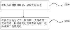
根据当前的使用场景,确定充电方式;Determine the charging method according to the current usage scenario;
在预设充电方式下,控制第一支路或第二支路连通,以通过所述充电管理芯片为第一电池或第二电池充电。In the preset charging mode, the first branch or the second branch is controlled to be connected to charge the first battery or the second battery through the charging management chip.
在一些实施例中,所述方法还包括:In some embodiments, the method further includes:
响应于连接充电器且所述控制芯片处于第一状态,确定所述使用场景为第一场景;或者,In response to connecting the charger and the control chip is in the first state, determining that the usage scenario is the first scenario; or,
响应于连接充电器且所述控制芯片处于第二状态,确定所述使用场景为第二场景;或者,In response to connecting the charger and the control chip is in the second state, determining that the usage scenario is the second scenario; or,
响应于未连接充电器且所述控制芯片处于第二状态,以及所述第一电池的电压大于所述第二电池的电压时,确定所述使用场景为第三场景;In response to that the charger is not connected and the control chip is in the second state, and the voltage of the first battery is greater than the voltage of the second battery, determining that the usage scenario is a third scenario;
其中,所述控制芯片在第一状态下的功耗大于第二状态下的功耗。Wherein, the power consumption of the control chip in the first state is greater than the power consumption in the second state.
在一些实施例中,所述根据当前的使用场景,确定充电方式,包括:In some embodiments, determining the charging method according to the current usage scenario includes:
响应于所述使用场景为第一场景,确定充电方式为第一方式;或者,In response to the usage scenario being the first scenario, determining that the charging mode is the first mode; or,
响应于所述使用场景为第二场景,确定充电方式为第二方式;或者,In response to the usage scenario being the second scenario, determining that the charging mode is the second mode; or,
响应于所述使用场景为第三场景,确定充电方式为第三方式。In response to the usage scenario being the third scenario, it is determined that the charging mode is the third mode.
在一些实施例中,所述预设充电方式为所述第一方式;In some embodiments, the preset charging mode is the first mode;
所述在预设充电方式下,控制第一支路或第二支路连通,包括:In the preset charging mode, controlling the connection of the first branch or the second branch includes:
在所述第一方式下,通过控制开关单元控制所述第一支路连通,并控制所述第二支路关闭;通过所述充电管理芯片以第一充电电流为所述第一电池充电;其中,所述第一充电电流不大于电流阈值。In the first mode, the first branch is controlled to be connected by the control switch unit, and the second branch is controlled to be closed; the first battery is charged with the first charging current through the charging management chip; Wherein, the first charging current is not greater than a current threshold.
在一些实施例中,所述预设充电方式为所述第二方式;In some embodiments, the preset charging mode is the second mode;
所述在预设充电方式下,控制第一支路或第二支路连通,包括:In the preset charging mode, controlling the connection of the first branch or the second branch includes:
在所述第二方式下,通过控制开关单元控制所述第一支路关闭,并控制所述第二支路连通,通过所述充电管理芯片以第二充电电流为所述第二电池充电;其中,所述第二充电电流大于电流阈值。In the second mode, the first branch is controlled to be closed by the control switch unit, and the second branch is controlled to be connected, and the second battery is charged with the second charging current through the charging management chip; Wherein, the second charging current is greater than the current threshold.
在一些实施例中,所述方法还包括:In some embodiments, the method further includes:
在所述第三方式下,控制负载切换芯片连通,以控制所述第一电池与所述第二电池连通,所述第一电池为所述第二电池供电。In the third mode, the load switching chip is controlled to be connected to control the communication between the first battery and the second battery, and the first battery supplies power to the second battery.
根据本公开实施例的第四方面,提出了一种充放电装置,应用于终端设备,装置包括:According to a fourth aspect of the embodiments of the present disclosure, a charging and discharging device is proposed, which is applied to terminal equipment, and the device includes:
确定模块,用于根据当前的使用场景,确定充电方式;The determination module is used to determine the charging method according to the current usage scenario;
控制模块,用于在预设充电方式下,控制第一支路或第二支路连通,以通过所述充电管理芯片为第一电池或第二电池充电。The control module is configured to control the connection of the first branch or the second branch in a preset charging mode, so as to charge the first battery or the second battery through the charging management chip.
根据本公开实施例的第五方面,提出了一种终端设备,包括:According to a fifth aspect of the embodiments of the present disclosure, a terminal device is proposed, including:
处理器;processor;
用于存储处理器的可执行指令的存储器;memory for storing executable instructions for the processor;
其中,所述处理器被配置为执行如上任一项所述的充放电方法。Wherein, the processor is configured to execute the charging and discharging method as described in any one of the above.
根据本公开实施例的第六方面,提出了一种非临时性计算机可读存储介质,当所述存储介质中的指令由终端设备的处理器执行时,使得终端设备能够执行如上任一项所述的充放电方法。According to a sixth aspect of the embodiments of the present disclosure, a non-transitory computer-readable storage medium is proposed. When an instruction in the storage medium is executed by a processor of a terminal device, the terminal device can execute the above-mentioned method. the charging and discharging method described above.
本公开的实施例提供的技术方案可以包括以下有益效果:The technical solutions provided by the embodiments of the present disclosure may include the following beneficial effects:
本公开的结构中,根据充电的使用场景不同,可动态选择不同的充电方式,充电方式更灵活。本实施例中在对应的使用场景下,可控制仅为第一电池充电,结合第一电池的容量限制,可降低充电电流以及充电功率,从而降低充电过程的功耗,有效降低充电过程的发热量。进而可降低整机热量,在不影响使用体验的前提下,更贴合用户的使用需求并有效提升使用体验。In the structure of the present disclosure, according to different charging usage scenarios, different charging modes can be dynamically selected, and the charging mode is more flexible. In this embodiment, in the corresponding usage scenario, only the first battery can be controlled to be charged. Combined with the capacity limit of the first battery, the charging current and charging power can be reduced, thereby reducing the power consumption of the charging process and effectively reducing the occurrence of the charging process. heat. In turn, the heat of the whole machine can be reduced, and on the premise of not affecting the use experience, it is more suitable for the user's use needs and effectively improves the use experience.
应当理解的是,以上的一般描述和后文的细节描述仅是示例性和解释性的,并不能限制本公开。It is to be understood that the foregoing general description and the following detailed description are exemplary and explanatory only and are not restrictive of the present disclosure.
附图说明Description of drawings
此处的附图被并入说明书中并构成本说明书的一部分,示出了符合本发明的实施例,并与说明书一起用于解释本发明的原理。The accompanying drawings, which are incorporated in and constitute a part of this specification, illustrate embodiments consistent with the invention and together with the description serve to explain the principles of the invention.
图1是根据一示例性实施例示出的充放电系统的拓扑结构示意图。FIG. 1 is a schematic diagram of a topology structure of a charging and discharging system according to an exemplary embodiment.
图2是根据一示例性实施例示出的方法的流程图。FIG. 2 is a flowchart of a method according to an exemplary embodiment.
图3是根据一示例性实施例示出的方法的流程图。FIG. 3 is a flowchart of a method according to an exemplary embodiment.
图4是根据一示例性实施例示出的供电示意图。FIG. 4 is a schematic diagram of power supply according to an exemplary embodiment.
图5是根据一示例性实施例示出的方法的流程图。FIG. 5 is a flowchart of a method according to an exemplary embodiment.
图6是根据一示例性实施例示出的装置的框图。Fig. 6 is a block diagram of an apparatus according to an exemplary embodiment.
图7是根据一示例性实施例示出的终端设备的框图。Fig. 7 is a block diagram of a terminal device according to an exemplary embodiment.
具体实施方式Detailed ways
这里将详细地对示例性实施例进行说明,其示例表示在附图中。下面的描述涉及附图时,除非另有表示,不同附图中的相同数字表示相同或相似的要素。以下示例性实施例中所描述的实施方式并不代表与本发明相一致的所有实施方式。相反,它们仅是与如所附权利要求书中所详述的、本发明的一些方面相一致的装置和方法的例子。Exemplary embodiments will be described in detail herein, examples of which are illustrated in the accompanying drawings. Where the following description refers to the drawings, the same numerals in different drawings refer to the same or similar elements unless otherwise indicated. The implementations described in the illustrative examples below are not intended to represent all implementations consistent with the present invention. Rather, they are merely examples of apparatus and methods consistent with some aspects of the invention as recited in the appended claims.
相关技术中,终端设备的电池结构通常包括如下两种方案:In the related art, the battery structure of the terminal device usually includes the following two solutions:
第一、采用容量大的单电池结构,即保证终端设备的续航能力又可方便控制成本。First, a single battery structure with large capacity is adopted, which not only ensures the endurance of the terminal equipment but also facilitates cost control.
第二、采用同等容量的双电池结构,续航能力好但成本高。Second, the dual-battery structure with the same capacity is adopted, which has good battery life but high cost.
上述两种电池结构中,充电方式一般较为固定,按照设定的或线性的功率充电。在一些场景下,可能存在用户体验差的问题。比如,在边充电边使用(如边充电边游戏)的场景中,会存在充电过程和负载两部分功耗,这两部分功耗所产生的发热导致终端设备的发热问题更为严重。In the above two battery structures, the charging method is generally relatively fixed, charging according to a set or linear power. In some scenarios, there may be a problem of poor user experience. For example, in the scenario of using while charging (such as gaming while charging), there will be two parts of power consumption in the charging process and the load, and the heat generated by these two parts of power consumption will make the heating problem of the terminal equipment more serious.
相关技术中,在解决边充电边使用场景中所存在的发热问题时,通常采用如下方法:In the related art, the following methods are usually adopted to solve the heating problem in the usage scenario while charging:
保持相关技术的充电方式,并在充电过程中通过降低中央处理器(CPU)频率降低发热量。但此种方式中,降低CPU频率的同时,会降低用户正在使用的程序性能,如游戏性能。因此此种方式会严重影响用户的体验。Maintain the charging method of the related technology, and reduce the heat generation by reducing the frequency of the central processing unit (CPU) during the charging process. However, in this way, while reducing the CPU frequency, the performance of the program being used by the user, such as the game performance, will be reduced. Therefore, this method will seriously affect the user experience.
为解决相关技术中的问题,本公开提出了一种充放电系统,包括:控制芯片;第一电池和第二电池,第二电池的容量大于第一电池的容量,第一电池的容量不大于设定阈值;充电管理芯片,与控制芯片连接,通过第一支路与第一电池连接,并通过第二支路与第二电池连接,充电管理芯片还用于与充电器连接;其中,控制芯片用于:根据当前使用场景控制第一支路或第二支路连通,以通过充电管理芯片为第一电池或第二电池充电。本公开的结构中,根据充电的使用场景不同,可动态选择不同的充电方式,充电方式更灵活。本实施例中在对应的使用场景下,可控制仅为第一电池充电,结合第一电池的容量限制,可降低充电电流以及充电功率,从而降低充电过程的功耗,有效降低充电过程的发热量。进而可降低整机热量,在不影响使用体验的前提下,更贴合用户的使用需求并有效提升使用体验。In order to solve the problems in the related art, the present disclosure proposes a charging and discharging system, comprising: a control chip; a first battery and a second battery, the capacity of the second battery is greater than that of the first battery, and the capacity of the first battery is not greater than Set the threshold value; the charging management chip is connected to the control chip, connected to the first battery through the first branch, and connected to the second battery through the second branch, and the charging management chip is also used to connect with the charger; wherein, the control The chip is used for: controlling the connection of the first branch or the second branch according to the current usage scenario, so as to charge the first battery or the second battery through the charging management chip. In the structure of the present disclosure, according to different charging usage scenarios, different charging modes can be dynamically selected, and the charging mode is more flexible. In this embodiment, in the corresponding usage scenario, only the first battery can be controlled to be charged. Combined with the capacity limit of the first battery, the charging current and charging power can be reduced, thereby reducing the power consumption of the charging process and effectively reducing the occurrence of the charging process. heat. In turn, the heat of the whole machine can be reduced, and on the premise of not affecting the use experience, it is more suitable for the user's use needs and effectively improves the use experience.
在一个示例性的实施例中,比如在功耗较大的使用场景下,实施例的充放电系统,可应用于终端设备中。其中,终端设备可以是手机、平板电脑、笔记本电脑等电子设备。In an exemplary embodiment, for example, in a usage scenario with high power consumption, the charging and discharging system of the embodiment can be applied to a terminal device. The terminal device may be an electronic device such as a mobile phone, a tablet computer, and a notebook computer.
如图1所示,本实施例中充放电系统包括:控制芯片10、第一电池20、第二电池30、充电管理芯片40、第一支路101以及第二支路102。As shown in FIG. 1 , the charging and discharging system in this embodiment includes: a
第二电池30的容量大于第一电池20的容量,第一电池20的容量不大于设定阈值。The capacity of the
充电管理芯片40与控制芯片10连接,并通过第一支路101与第一电池20连接,通过第二支路102与第二电池30连接,充电管理芯片40还用于与充电器100连接。The
其中,控制芯片10用于:根据当前使用场景控制第一支路101或第二支路102连通,以通过充电管理芯片40为第一电池20或第二电池30充电。The
本实施例中,控制芯片10可以是系统级芯片(SOC),如可集成终端设备的CPU。第二电池30仍采用大容量电池,例如,第二电池30的容量设置为5000mAh。设定阈值比如设置为1000mAh,第一电池20的容量小于或等于设定阈值,并小于第二电池30的容量。In this embodiment, the
其中,第二电池30的容量与第一电池20的容量可以是满足设定的差值,或者满足设定的比例。比如,第二电池30的容量是第一电池20的容量的5倍或10倍,第一电池20的容量设置为1000mAh或500mAh。本实施例中,第一电池20的容量设置为500mAh。Wherein, the capacity of the
本实施例中,控制芯片10根据充电管理芯片40的充放电情况,可获知系统功耗或负载情况。使用场景至少包括:第一场景和第二场景,当前的使用场景可以是第一场景或第二场景。其中,第一场景下的功耗大于第二场景下的功耗,第一场景如为:边充电边游戏场景,第二场景如为:仅充电场景。控制芯片10在第一场景中处于第一状态(表征重载状态),在第二场景中处于第二状态(表征轻载状态)。In this embodiment, the
控制芯片10根据当前使用场景的不同,调整充电方式。The
在一个示例中,控制芯片10确定处于第一场景时,系统负载(system load)50功耗较大,可控制第一支路101连通、第二支路102断开,充电管理芯片(charger IC)40基于与充电器(adapter)100的连接,同时为系统负载50和第一电池20充电。系统负载50如包括游戏负载。第一场景例如是边充电边游戏的场景,此场景中控制芯片10一般处于第一状态即重载状态,系统功耗包括系统负载50功耗及充电功耗。In an example, when the
本示例中,第一电池20的容量小,因此可有效降低充电电流和充电功率,充电过程功耗占用小、充电时间短,从而降低充电过程的发热程度,可保持系统负载50处的功耗,进而有效提升用户在充电过程中进行游戏等操作的体验。In this example, the capacity of the
在另一个示例中,控制芯片10确定处于第二场景时,系统负载50功耗较小或没有,可控制第二支路102连通、第一支路101断开,充电管理芯片40基于与充电器100的连接,为第二电池30充电。本示例中,第二电池30的容量较大,充电电流、充电功率较大。第二场景例如是仅充电场景,此场景中控制芯片10一般处于第二状态即轻载状态。In another example, when the
本公开实施例中,至少可从如下两方面提升用户体验:在第一场景下,不仅可以降低充电过程的功耗及热量,保持用户的使用体验如游戏体验,还可以缩短充电时间。而在第二场景下,可保持较好的充电体验及充电速度。In the embodiments of the present disclosure, the user experience can be improved from at least the following two aspects: in the first scenario, not only can the power consumption and heat of the charging process be reduced, the user experience such as game experience can be maintained, but also the charging time can be shortened. In the second scenario, a better charging experience and charging speed can be maintained.
从而在多个场景下选取对应的充电方式,实现在不同场景下有效贴合用户的不同需求。Therefore, the corresponding charging method can be selected in multiple scenarios to effectively meet the different needs of users in different scenarios.
在一个示例性的实施例中,如图1所示,本实施例中充放电系统还包括:充电通路管理单元(power path IC)60。In an exemplary embodiment, as shown in FIG. 1 , the charging and discharging system in this embodiment further includes: a charging path management unit (power path IC) 60 .
充电通路管理单元60通过充电管理芯片40与控制芯片10连接。充电管理芯片40或第二电池30通过充电通路管理单元60为系统负载50供电。The charging
其中,控制芯片10通过充电管理芯片40获取充放电情况,例如可获知充电通路管理单元60处系统负载50的耗电情况,根据耗电情况即可获知当前系统负载50的功耗,从而获知控制芯片10的状态,如为重载状态或轻载状态。The
本实施例中,控制芯片10的控制信号可通过充电管理芯片40告知充电通路管理单元60。充电通路管理单元60根据控制信号,控制与充电管理芯片40之间的供电支路连通;或者,控制与第二电池30之间的供电支路连通。In this embodiment, the control signal of the
在一个示例中,当连接充电器100时,控制芯片10可控制:充电管理芯片40通过充电通路管理单元60为系统负载50供电。在另一个示例中,当未连接充电器100时,控制芯片10可控制:第二电池30通过充电通路管理单元60为系统负载50供电。In one example, when the
在存在系统负载50,并连接充电器100时,充电管理芯片40的供电可包括两部分。一部分通过充电通路管理单元60为系统负载50供电,一部分通过第一支路101为第一电池20充电,或通过第二支路102为第二电池30充电。When the
在一个示例性的实施例中,如图1所示,本实施例的充放电系统还包括:开关单元70。In an exemplary embodiment, as shown in FIG. 1 , the charging and discharging system of this embodiment further includes: a
充电管理芯片40通过开关单元分别与第一支路101和第二支路102连接。控制芯片10与开关单元70连接,控制芯片10用于控制开关单元70的连通方式,以控制开关单元70与第一支路101或第二支路102连通。The
其中,开关单元70可以是开关芯片(switch IC)或者设置为单刀双掷开关。通过控制开关单元70的不同连通状态,控制充电管理芯片40与第一支路101连通,为第一电池20充电;或者,控制充电管理芯片40与第二支路102连通,为第二电池30充电。The
本实施例中,通过与第一支路101和第二支路102连接的开关单元70,实现控制充电管理芯片40所连接的支路是否连通。In this embodiment, through the
在本公开的其他示例中,还可以在第一支路101和第二支路102上分别设置开关,通过控制两个支路上开关的开或关,控制开关所在支路是否连通。In other examples of the present disclosure, switches may be provided on the
在一个示例性的实施例中,如图1所示,本实施例的充放电系统还包括:比较单元80,与控制芯片10连接。In an exemplary embodiment, as shown in FIG. 1 , the charging and discharging system of this embodiment further includes: a
第一电池20通过比较单元80与第二电池30连接;控制芯片10用于:通过比较单元80获取第一电池20与第二电池30的电压关系。The
本实施例中,比较单元(comparator IC)80用于检测第一电池20与第二电池30的电压大小,并可向控制芯片10上报第一电池20与第二电池30的电压关系。In this embodiment, the
在一个示例性的实施例中,如图1所示,本实施例的充放电系统还包括:负载切换芯片90,与控制芯片10连接。In an exemplary embodiment, as shown in FIG. 1 , the charging and discharging system of this embodiment further includes: a
第一电池20通过负载切换芯片90与第二电池30连接。控制芯片10用于:通过控制负载切换芯片90连通,控制第一电池20与第二电池30连通,以使第一电池20为第二电池30供电。The
其中,使用场景还包括第三场景,本实施例可应用于第三场景中。第三场景满足如下三个限定条件:未连接充电器、控制芯片10处于第二状态(即轻载状态)而未处于第一状态(重载状态)、控制芯片10根据比较单元80获知第一电池20的电压大于第二电池30的电压。The usage scenario further includes a third scenario, and this embodiment can be applied to the third scenario. The third scenario satisfies the following three qualification conditions: the charger is not connected, the
在第三场景中,控制芯片10控制负载切换芯片90连通,以控制第一电池20与第二电池30连通,从而可使第一电池20为第二电池30供电。本公开实施例中,在合适的场景下,第一电池20还可为第二电池30充电,有效扩展本实施例的使用场景。In the third scenario, the
可以理解的,在本公开实施例中,第二电池30为终端设备的主供电电池,终端设备中进行电量统计等操作时可仅统计第二电池30。It can be understood that, in the embodiment of the present disclosure, the
在一个示例性的实施例中,本公开实施例还提出了一种终端设备,包括如图1所示的充放电系统。其中,图1中虚线连接表示控制信号(control)传输,实线连接表示供电(power)传输。In an exemplary embodiment, an embodiment of the present disclosure further provides a terminal device, including the charging and discharging system as shown in FIG. 1 . Wherein, the dotted line connection in FIG. 1 represents control signal (control) transmission, and the solid line connection represents power supply (power) transmission.
在一个示例性的实施例中,本公开实施例还提出了一种充放电方法,应用于终端设备,终端设备包括图1所示的充放电系统。In an exemplary embodiment, an embodiment of the present disclosure further proposes a charging and discharging method, which is applied to a terminal device, where the terminal device includes the charging and discharging system shown in FIG. 1 .
如图2所示,本实施例的方法可以包括如下步骤:As shown in FIG. 2, the method of this embodiment may include the following steps:
S210、根据当前的使用场景,确定充电方式。S210. Determine a charging mode according to the current usage scenario.
S220、在预设充电方式下,控制第一支路或第二支路连通,以通过充电管理芯片为第一电池或第二电池充电。S220. In the preset charging mode, control the first branch or the second branch to be connected, so as to charge the first battery or the second battery through the charging management chip.
其中,在步骤S210中,结合图1对应的实施例,终端设备的控制芯片10根据充电管理芯片40的充放电情况,可确定当前的使用场景。充放电情况可反映系统功耗或负载情况,结合不同的使用场景,本步骤中,控制芯片10可采用不同的充电方式。Wherein, in step S210 , with reference to the embodiment corresponding to FIG. 1 , the
在步骤S220中,结合图1对应的实施例,第二电池30的容量大于第一电池20的容量,第一电池20的容量不大于设定阈值。比如,第一电池20的容量为500mAh,第二电池30的容量为5000mAh。充电管理芯片40通过第一支路101与第一电池20连接,通过第二支路102与第二电池30连接。In step S220 , with reference to the embodiment corresponding to FIG. 1 , the capacity of the
本步骤中,在控制芯片10的控制下,充电管理芯片40可控制第一支路101连通、第二支路102断开,为第一电池20充电。或者,控制第一支路101断开、第二支路102连通,为第二电池30充电。In this step, under the control of the
在一个示例性的实施例中,本实施例的方法包括图2中步骤S210至步骤S220,本实施例的方法还可以包括:S200、确定当前的使用场景。In an exemplary embodiment, the method of this embodiment includes steps S210 to S220 in FIG. 2 , and the method of this embodiment may further include: S200 , determining a current usage scenario.
其中,步骤S200的实施方式可以包括如下中的一种:Wherein, the implementation of step S200 may include one of the following:
S201、响应于连接充电器且控制芯片处于第一状态,确定使用场景为第一场景。S201. In response to connecting the charger and the control chip is in the first state, determine that the usage scenario is the first scenario.
S202、响应于连接充电器且控制芯片处于第二状态,确定使用场景为第二场景。S202. In response to connecting the charger and the control chip is in the second state, determine that the usage scenario is the second scenario.
S203、响应于未连接充电器且控制芯片处于第二状态,以及第一电池的电压大于第二电池的电压时,确定使用场景为第三场景。S203. In response to the charger not being connected and the control chip being in the second state, and the voltage of the first battery being greater than the voltage of the second battery, determine that the usage scenario is the third scenario.
其中,控制芯片在第一状态下的功耗大于第二状态下的功耗。结合图1对应的实施例,第一状态用于表征控制芯片10处于重载状态下,例如,系统负载50占用的功耗大于或等于功耗阈值;第二状态用于表征控制芯片10处于轻载状态下,例如,系统负载50占用的功耗小于功耗阈值。Wherein, the power consumption of the control chip in the first state is greater than the power consumption in the second state. With reference to the embodiment corresponding to FIG. 1 , the first state is used to indicate that the
控制芯片10通过充电管理芯片40获取充放电情况,例如可获知充电通路管理单元60处系统负载50的耗电情况,根据耗电情况即可获知当前系统负载50的功耗,从而获知控制芯片10的状态,如为重载状态或轻载状态。The
在步骤S201及步骤S202中,当终端设备与充电器100连接,根据控制芯片10所处的状态不同,对应的使用场景为第一场景或第二场景。In step S201 and step S202, when the terminal device is connected to the
在步骤S203中,当终端设备未与充电器100连接,且控制芯片处于轻载状态,控制芯片10可根据比较单元80获取第一电池20与第二电池30间的电压关系。当此时第一电池20的电压大于第二电池30的电压时,对应的使用场景为第三场景。第三场景中,可利用第一电池20为第二电池30供电。In step S203 , when the terminal device is not connected to the
在一个示例性的实施例中,预设充电方式为第一方式。如图3所示,本实施例的方法包括如下步骤:In an exemplary embodiment, the preset charging mode is the first mode. As shown in Figure 3, the method of this embodiment includes the following steps:
S300、连接充电器,确定控制芯片是否处于第一状态,若是,执行步骤S301。若否,执行步骤S401。S300. Connect the charger to determine whether the control chip is in the first state, and if so, perform step S301. If not, go to step S401.
S301、响应于连接充电器且控制芯片处于第一状态,确定使用场景为第一场景。S301. In response to connecting the charger and the control chip is in the first state, determine that the usage scenario is the first scenario.
S302、响应于使用场景为第一场景,确定充电方式为第一方式。S302. In response to the use scenario being the first scenario, determine that the charging mode is the first mode.
S303、在第一方式下,通过控制开关单元控制第一支路连通,并控制第二支路关闭,通过充电管理芯片以第一充电电流为第一电池充电。S303. In the first mode, the first branch is controlled to be connected by the control switch unit, and the second branch is controlled to be closed, and the first battery is charged with the first charging current through the charging management chip.
其中,在步骤S300中,结合图1以及前述实施例,在连接充电器100后,控制芯片10可通过充电管理芯片40获取充放电情况,例如可获知充电通路管理单元60处系统负载50的耗电情况,确定是否处于第一状态、即重载状态。若否,则认为控制芯片10处于第二状态、即轻载状态。Wherein, in step S300 , with reference to FIG. 1 and the foregoing embodiments, after connecting the
步骤S301的实施方式可参见步骤S201,此处不再赘述。For the implementation of step S301, reference may be made to step S201, which will not be repeated here.
在步骤S302中,根据第一场景,确定对应的充电方式为第一方式。In step S302, according to the first scenario, it is determined that the corresponding charging mode is the first mode.
在步骤S303中,控制芯片10控制开关单元70的连通方式,使开关单元70与第一支路101连通,而与第二支路102断开。从而,充电管理芯片40通过第一支路101以第一充电电流为第一电池20充电。其中,结合第一电池20的容量,第一充电电流为小电流参数,不大于(小于或等于)预先设定的电流阈值。In step S303 , the
本步骤中,结合图4所示,连接充电器100时,充电管理芯片40还可通过充电通路管理单元60为系统负载50供电。In this step, as shown in FIG. 4 , when the
在一个示例性的实施例中,预设充电方式为第二方式。依旧参照图3所示,本实施例的方法包括如下步骤:In an exemplary embodiment, the preset charging mode is the second mode. Still referring to FIG. 3 , the method of this embodiment includes the following steps:
S401、响应于连接充电器且控制芯片处于第二状态,确定使用场景为第二场景。S401. In response to connecting the charger and the control chip is in the second state, determine that the usage scenario is the second scenario.
S402、响应于所述使用场景为第二场景,确定充电方式为第二方式。S402. In response to the use scenario being the second scenario, determine that the charging mode is the second mode.
S403、在第二方式下,控制充电管理芯片为系统负载供电;控制第一支路连通,第二支路关闭,以通过充电管理芯片为第一电池充电。S403. In the second mode, control the charging management chip to supply power to the system load; control the first branch to be connected and the second branch to be closed, so as to charge the first battery through the charging management chip.
其中,步骤S401的实施方式可参见步骤S202,此处不再赘述。The implementation of step S401 may refer to step S202, which will not be repeated here.
在步骤S402中,根据第二场景,确定对应的充电方式为第二方式。In step S402, according to the second scenario, it is determined that the corresponding charging mode is the second mode.
在步骤S403中,在第二方式中,控制芯片10控制开关单元70的连通方式,使开关单元70与第二支路102连通,而与第一支路101断开。从而,充电管理芯片40通过第二支路102以第二充电电流为第二电池30充电。其中,第二充电电流大于电流阈值,且大于第一充电电流。In step S403 , in the second mode, the
结合图4所示,在未与充电器100连接,或者在本实施例第二电池30充满电、与充电器100断开连接后,第二电池30可为系统负载50供电。With reference to FIG. 4 , the
在一个示例性的实施例中,如图5所示,本实施例的方法包括如下步骤:In an exemplary embodiment, as shown in FIG. 5 , the method of this embodiment includes the following steps:
S500-1、确定是否连接充电器。若是,执行步骤S500-2;若否,执行步骤S504。S500-1. Determine whether to connect the charger. If yes, go to step S500-2; if not, go to step S504.
S500-2、确定控制芯片是否处于第二状态。若是,执行步骤S500-3;若否,执行步骤S504。S500-2. Determine whether the control chip is in the second state. If yes, go to step S500-3; if not, go to step S504.
S500-3、确定第一电池的电压是否大于第二电池的电压。若是,执行步骤S501;若否,执行步骤S504。S500-3. Determine whether the voltage of the first battery is greater than the voltage of the second battery. If yes, go to step S501; if not, go to step S504.
S501、响应于未连接充电器且控制芯片处于第二状态,以及第一电池的电压大于第二电池的电压时,确定使用场景为第三场景。S501. In response to that the charger is not connected and the control chip is in the second state, and the voltage of the first battery is greater than the voltage of the second battery, determine that the usage scenario is the third scenario.
S502、响应于使用场景为第三场景,确定充电方式为第三方式。S502. In response to the use scenario being the third scenario, determine that the charging mode is the third mode.
S503、在第三方式下,控制负载切换芯片连通,以控制第一电池与第二电池连通,第一电池为第二电池供电。S503. In the third mode, the load switching chip is controlled to be connected to control the communication between the first battery and the second battery, and the first battery supplies power to the second battery.
S504、控制负载切换芯片断开,以控制第一电池与第二电池断开。S504, control the load switching chip to be disconnected, so as to control the disconnection of the first battery and the second battery.
其中,本实施例中步骤S500-1至步骤S500-3的判决顺序仅作示意,三个条件的判决顺序可根据需要调整。Wherein, the judgment order of steps S500-1 to S500-3 in this embodiment is only for illustration, and the judgment order of the three conditions can be adjusted as required.
步骤S501的实施方式可参见步骤S203,此处不再赘述。For the implementation of step S501, reference may be made to step S203, which will not be repeated here.
在步骤S502中,根据第三场景,确定对应的充电方式为第三方式。In step S502, according to the third scenario, it is determined that the corresponding charging mode is the third mode.
在步骤S503中,结合图1及前述实施例,控制芯片10在确定满足如上三个条件后,可控制负载切换芯片90连通,以控制第一电池20与第二电池30连通,从而可使第一电池20为第二电池30供电。In step S503, with reference to FIG. 1 and the foregoing embodiments, after determining that the above three conditions are satisfied, the
在步骤S504中,控制芯片10在确定不满足如上三个条件中的任一个时,控制负载切换芯片90断开,以控制第一电池20与第二电池30断开,第一电池20不为第二电池30供电。In step S504, when the
本公开实施例中,结合不同的使用场景,更贴合的选取对应的充电方式,从而能够更贴合用户在不同场景下的需求与体验。In the embodiment of the present disclosure, in combination with different usage scenarios, a corresponding charging method is more appropriately selected, so as to better suit the needs and experience of users in different scenarios.
对于第一场景,如边充电边游戏这种功耗较大的场景中,通过调整充电过程仅为第一电池20充电,来降低充电电流及充电功率,从而降低充电过程的功耗及发热,降低终端设备的整体发热现象。而不需降低控制芯片10的频率,利于保证使用过程中的性能,更适应于用户在此种场景中对游戏体验要求较高的需求。For the first scenario, for example, in a scenario with high power consumption such as a game while charging, only the
对于第二场景,可保持充电的速度及充电功率,有效贴合用户的充电需求,保证用户的充电体验。For the second scenario, the charging speed and charging power can be maintained to effectively meet the user's charging needs and ensure the user's charging experience.
对于第三场景,还可利用第一电池20为第二电池30充电,扩展了第一电池20的使用场景。For the third scenario, the
在一个示例性的实施例中,本公开实施例还提出了一种充放电装置,用于执行前述实施例的充放电方法。如图6所示,本实施例的装置包括:确定模块610及控制模块620。其中,确定模块610用于根据当前的使用场景,确定充电方式。控制模块620用于在预设充电方式下,控制第一支路或第二支路连通,以通过充电管理芯片为第一电池或第二电池充电。In an exemplary embodiment, an embodiment of the present disclosure further provides a charging and discharging device for performing the charging and discharging method of the foregoing embodiment. As shown in FIG. 6 , the apparatus of this embodiment includes: a
如图7所示是一种终端设备的框图。本公开还提供了一种终端设备,例如,设备500可以是移动电话,计算机,数字广播终端,消息收发设备,游戏控制台,平板设备,医疗设备,健身设备,个人数字助理等。Figure 7 is a block diagram of a terminal device. The present disclosure also provides a terminal device, for example, the device 500 may be a mobile phone, a computer, a digital broadcast terminal, a messaging device, a game console, a tablet device, a medical device, a fitness device, a personal digital assistant, and the like.
设备500可以包括以下一个或多个组件:处理组件502,存储器504,电力组件506,多媒体组件508,音频组件510,输入/输出(I/O)的接口512,传感器组件514,以及通信组件516。Device 500 may include one or more of the following components: processing
处理组件502通常控制设备500的整体操作,诸如与显示,电话呼叫,数据通信,相机操作和记录操作相关联的操作。处理组件502可以包括一个或多个处理器520来执行指令,以完成上述的方法的全部或部分步骤。此外,处理组件502可以包括一个或多个模块,便于处理组件502和其他组件之间的交互。例如,处理组件502可以包括多媒体模块,以方便多媒体组件508和处理组件502之间的交互。The
存储器504被配置为存储各种类型的数据以支持在设备500的操作。这些数据的示例包括用于在设备500上操作的任何应用程序或方法的指令,联系人数据,电话簿数据,消息,图片,视频等。存储器504可以由任何类型的易失性或非易失性存储设备或者它们的组合实现,如静态随机存取存储器(SRAM),电可擦除可编程只读存储器(EEPROM),可擦除可编程只读存储器(EPROM),可编程只读存储器(PROM),只读存储器(ROM),磁存储器,快闪存储器,磁盘或光盘。Memory 504 is configured to store various types of data to support operation at device 500 . Examples of such data include instructions for any application or method operating on device 500, contact data, phonebook data, messages, pictures, videos, and the like. Memory 504 may be implemented by any type of volatile or non-volatile storage device or combination thereof, such as static random access memory (SRAM), electrically erasable programmable read only memory (EEPROM), erasable Programmable Read Only Memory (EPROM), Programmable Read Only Memory (PROM), Read Only Memory (ROM), Magnetic Memory, Flash Memory, Magnetic or Optical Disk.
电力组件506为设备500的各种组件提供电力。电力组件506可以包括电源管理系统,一个或多个电源,及其他与为装置500生成、管理和分配电力相关联的组件。Power component 506 provides power to various components of device 500 . Power components 506 may include a power management system, one or more power sources, and other components associated with generating, managing, and distributing power to device 500 .
多媒体组件508包括在设备500和用户之间的提供一个输出接口的屏幕。在一些实施例中,屏幕可以包括液晶显示器(LCD)和触摸面板(TP)。如果屏幕包括触摸面板,屏幕可以被实现为触摸屏,以接收来自用户的输入信号。触摸面板包括一个或多个触摸传感器以感测触摸、滑动和触摸面板上的手势。触摸传感器可以不仅感测触摸或滑动动作的边界,而且还检测与触摸或滑动操作相关的持续时间和压力。在一些实施例中,多媒体组件508包括一个前置摄像头和/或后置摄像头。当设备500处于操作模式,如拍摄模式或视频模式时,前置摄像头和/或后置摄像头可以接收外部的多媒体数据。每个前置摄像头和后置摄像头可以是一个固定的光学透镜系统或具有焦距和光学变焦能力。Multimedia component 508 includes screens that provide an output interface between device 500 and the user. In some embodiments, the screen may include a liquid crystal display (LCD) and a touch panel (TP). If the screen includes a touch panel, the screen may be implemented as a touch screen to receive input signals from a user. The touch panel includes one or more touch sensors to sense touch, swipe, and gestures on the touch panel. A touch sensor can sense not only the boundaries of a touch or swipe action, but also the duration and pressure associated with the touch or swipe action. In some embodiments, the multimedia component 508 includes a front-facing camera and/or a rear-facing camera. When the device 500 is in an operation mode, such as a shooting mode or a video mode, the front camera and/or the rear camera may receive external multimedia data. Each of the front and rear cameras can be a fixed optical lens system or have focal length and optical zoom capability.
音频组件510被配置为输出和/或输入音频信号。例如,音频组件510包括一个麦克风(MIC),当设备500处于操作模式,如呼叫模式、记录模式和语音识别模式时,麦克风被配置为接收外部音频信号。所接收的音频信号可以被进一步存储在存储器504或经由通信组件516发送。在一些实施例中,音频组件510还包括一个扬声器,用于输出音频信号。Audio component 510 is configured to output and/or input audio signals. For example, audio component 510 includes a microphone (MIC) that is configured to receive external audio signals when device 500 is in operating modes, such as call mode, recording mode, and voice recognition mode. The received audio signal may be further stored in memory 504 or transmitted via communication component 516 . In some embodiments, the audio component 510 also includes a speaker for outputting audio signals.
I/O接口512为处理组件502和外围接口模块之间提供接口,上述外围接口模块可以是键盘,点击轮,按钮等。这些按钮可包括但不限于:主页按钮、音量按钮、启动按钮和锁定按钮。The I/O interface 512 provides an interface between the
传感器组件514包括一个或多个传感器,用于为设备500提供各个方面的状态评估。例如,传感器组件514可以检测到设备500的打开/关闭状态,组件的相对定位,例如组件为设备500的显示器和小键盘,传感器组件514还可以检测设备500或设备500一个组件的位置改变,用户与设备500接触的存在或不存在,设备500方位或加速/减速和装置500的温度变化。传感器组件514可以包括接近传感器,被配置用来在没有任何的物理接触时检测附近物体的存在。传感器组件514还可以包括光传感器,如CMOS或CCD图像传感器,用于在成像应用中使用。在一些实施例中,该传感器组件514还可以包括加速度传感器,陀螺仪传感器,磁传感器,压力传感器或温度传感器。Sensor assembly 514 includes one or more sensors for providing status assessments of various aspects of device 500 . For example, the sensor component 514 can detect the open/closed state of the device 500, the relative positioning of components, such as the display and keypad of the device 500, the sensor component 514 can also detect the position change of the device 500 or a component of the device 500, the user The presence or absence of contact with the device 500 , the orientation or acceleration/deceleration of the device 500 and the temperature change of the device 500 . Sensor assembly 514 may include a proximity sensor configured to detect the presence of nearby objects in the absence of any physical contact. Sensor assembly 514 may also include a light sensor, such as a CMOS or CCD image sensor, for use in imaging applications. In some embodiments, the sensor assembly 514 may also include an acceleration sensor, a gyroscope sensor, a magnetic sensor, a pressure sensor, or a temperature sensor.
通信组件516被配置为便于设备500和其他设备之间有线或无线方式的通信。设备500可以接入基于通信标准的无线网络,如WiFi,2G或3G,或它们的组合。在一个示例性实施例中,通信组件516经由广播信道接收来自外部广播管理系统的广播信号或广播相关信息。在一个示例性实施例中,通信组件516还包括近场通信(NFC)模块,以促进短程通信。例如,在NFC模块可基于射频识别(RFID)技术,红外数据协会(IrDA)技术,超宽带(UWB)技术,蓝牙(BT)技术和其他技术来实现。Communication component 516 is configured to facilitate wired or wireless communication between device 500 and other devices. Device 500 may access wireless networks based on communication standards, such as WiFi, 2G or 3G, or a combination thereof. In one exemplary embodiment, the communication component 516 receives broadcast signals or broadcast related information from an external broadcast management system via a broadcast channel. In one exemplary embodiment, the communication component 516 also includes a near field communication (NFC) module to facilitate short-range communication. For example, the NFC module may be implemented based on radio frequency identification (RFID) technology, infrared data association (IrDA) technology, ultra-wideband (UWB) technology, Bluetooth (BT) technology and other technologies.
在示例性实施例中,设备500可以被一个或多个应用专用集成电路(ASIC)、数字信号处理器(DSP)、数字信号处理设备(DSPD)、可编程逻辑器件(PLD)、现场可编程门阵列(FPGA)、控制器、微控制器、微处理器或其他电子元件实现,用于执行上述的方法。In an exemplary embodiment, device 500 may be implemented by one or more application specific integrated circuits (ASICs), digital signal processors (DSPs), digital signal processing devices (DSPDs), programmable logic devices (PLDs), field programmable A gate array (FPGA), controller, microcontroller, microprocessor or other electronic component implementation for performing the above-described method.
本公开另一个示例性实施例中提供的一种非临时性计算机可读存储介质,例如包括指令的存储器504,上述指令可由设备500的处理器520执行以完成上述方法。例如,计算机可读存储介质可以是ROM、随机存取存储器(RAM)、CD-ROM、磁带、软盘和光数据存储设备等。当存储介质中的指令由终端设备的处理器执行时,使得终端设备能够执行上述的方法。Another exemplary embodiment of the present disclosure provides a non-transitory computer-readable storage medium, such as a memory 504 including instructions that can be executed by the processor 520 of the device 500 to complete the above method. For example, the computer-readable storage medium may be ROM, random access memory (RAM), CD-ROM, magnetic tape, floppy disk, optical data storage device, and the like. When the instructions in the storage medium are executed by the processor of the terminal device, the terminal device is enabled to execute the above method.
本领域技术人员在考虑说明书及实践这里公开的发明后,将容易想到本发明的其它实施方案。本申请旨在涵盖本发明的任何变型、用途或者适应性变化,这些变型、用途或者适应性变化遵循本发明的一般性原理并包括本公开未公开的本技术领域中的公知常识或惯用技术手段。说明书和实施例仅被视为示例性的,本发明的真正范围和精神由下面的权利要求指出。Other embodiments of the invention will readily occur to those skilled in the art upon consideration of the specification and practice of the invention disclosed herein. This application is intended to cover any variations, uses, or adaptations of the invention that follow the general principles of the invention and include common knowledge or techniques in the art not disclosed by this disclosure . The specification and examples are to be regarded as exemplary only, with the true scope and spirit of the invention being indicated by the following claims.
应当理解的是,本发明并不局限于上面已经描述并在附图中示出的精确结构,并且可以在不脱离其范围进行各种修改和改变。本发明的范围仅由所附的权利要求来限制。It should be understood that the present invention is not limited to the precise structures described above and illustrated in the accompanying drawings, and that various modifications and changes may be made without departing from its scope. The scope of the present invention is limited only by the appended claims.
Claims (15)
Translated fromChinesePriority Applications (1)
| Application Number | Priority Date | Filing Date | Title |
|---|---|---|---|
| CN202210107024.1ACN114362326B (en) | 2022-01-28 | 2022-01-28 | Charging and discharging system, method and device, terminal equipment and storage medium |
Applications Claiming Priority (1)
| Application Number | Priority Date | Filing Date | Title |
|---|---|---|---|
| CN202210107024.1ACN114362326B (en) | 2022-01-28 | 2022-01-28 | Charging and discharging system, method and device, terminal equipment and storage medium |
Publications (2)
| Publication Number | Publication Date |
|---|---|
| CN114362326Atrue CN114362326A (en) | 2022-04-15 |
| CN114362326B CN114362326B (en) | 2024-07-16 |
Family
ID=81093817
Family Applications (1)
| Application Number | Title | Priority Date | Filing Date |
|---|---|---|---|
| CN202210107024.1AActiveCN114362326B (en) | 2022-01-28 | 2022-01-28 | Charging and discharging system, method and device, terminal equipment and storage medium |
Country Status (1)
| Country | Link |
|---|---|
| CN (1) | CN114362326B (en) |
Cited By (1)
| Publication number | Priority date | Publication date | Assignee | Title |
|---|---|---|---|---|
| CN115498290A (en)* | 2022-09-15 | 2022-12-20 | 湖北星纪时代科技有限公司 | Charging method of intelligent wearable device, storage medium, device and wearable device |
Citations (20)
| Publication number | Priority date | Publication date | Assignee | Title |
|---|---|---|---|---|
| JP2004140953A (en)* | 2002-10-18 | 2004-05-13 | Matsushita Electric Ind Co Ltd | Backup charging circuit |
| JP2006246595A (en)* | 2005-03-02 | 2006-09-14 | Sanyo Electric Co Ltd | Secondary battery pack |
| CN101355258A (en)* | 2007-07-27 | 2009-01-28 | 联想(新加坡)私人有限公司 | Method and apparatus for charging batteries |
| CN103633671A (en)* | 2012-08-21 | 2014-03-12 | 宏碁股份有限公司 | Multi-battery charging device and bidirectional charging method thereof |
| CN104218269A (en)* | 2014-09-22 | 2014-12-17 | 宇龙计算机通信科技(深圳)有限公司 | Charging method, charging system and charging terminal |
| CN204068306U (en)* | 2014-06-28 | 2014-12-31 | 青岛歌尔声学科技有限公司 | A kind of charging system of electronic product |
| JP2015029398A (en)* | 2013-06-26 | 2015-02-12 | 日東電工株式会社 | Power supply device, mobile device arranged by use thereof, and battery-type electric vehicle |
| US20150331472A1 (en)* | 2014-05-14 | 2015-11-19 | Honda Motor Co., Ltd. | Dual power supply system and electrically driven vehicle |
| CN105207312A (en)* | 2015-10-28 | 2015-12-30 | 湖南农业大学 | External standby battery system for mobile phone |
| CN105356561A (en)* | 2015-12-15 | 2016-02-24 | 广东顺德中山大学卡内基梅隆大学国际联合研究院 | Dual-battery charging-discharging system and method |
| CN105634055A (en)* | 2015-12-30 | 2016-06-01 | 宇龙计算机通信科技(深圳)有限公司 | Charging control method and charging control device of mobile terminal and mobile terminal |
| JP2016149876A (en)* | 2015-02-12 | 2016-08-18 | シャープ株式会社 | Charger |
| CN108683803A (en)* | 2018-04-26 | 2018-10-19 | 宁波亿拍客网络科技有限公司 | A kind of dual power supply mobile phone and movable equipment |
| CN109193830A (en)* | 2018-09-07 | 2019-01-11 | 杭州电子科技大学 | A kind of battery of mobile phone method of supplying power to |
| CN109525720A (en)* | 2018-10-31 | 2019-03-26 | 南昌努比亚技术有限公司 | Battery of mobile terminal control method, mobile terminal and readable storage medium storing program for executing |
| CN110086218A (en)* | 2019-04-08 | 2019-08-02 | 努比亚技术有限公司 | Cell partitions method, apparatus, electronic equipment and readable storage medium storing program for executing |
| CN210467933U (en)* | 2019-10-08 | 2020-05-05 | 东莞市茵莉电子有限公司 | Dual-output rechargeable battery |
| CN111133655A (en)* | 2018-05-09 | 2020-05-08 | 株式会社Lg化学 | Battery control device and energy storage system including the same |
| CN112770932A (en)* | 2019-01-15 | 2021-05-07 | 株式会社Lg化学 | Battery charging system and battery charging method |
| CN113964914A (en)* | 2021-11-08 | 2022-01-21 | 深圳市迪浦电子有限公司 | Mobile phone battery power supply management system and method |
- 2022
- 2022-01-28CNCN202210107024.1Apatent/CN114362326B/enactiveActive
Patent Citations (20)
| Publication number | Priority date | Publication date | Assignee | Title |
|---|---|---|---|---|
| JP2004140953A (en)* | 2002-10-18 | 2004-05-13 | Matsushita Electric Ind Co Ltd | Backup charging circuit |
| JP2006246595A (en)* | 2005-03-02 | 2006-09-14 | Sanyo Electric Co Ltd | Secondary battery pack |
| CN101355258A (en)* | 2007-07-27 | 2009-01-28 | 联想(新加坡)私人有限公司 | Method and apparatus for charging batteries |
| CN103633671A (en)* | 2012-08-21 | 2014-03-12 | 宏碁股份有限公司 | Multi-battery charging device and bidirectional charging method thereof |
| JP2015029398A (en)* | 2013-06-26 | 2015-02-12 | 日東電工株式会社 | Power supply device, mobile device arranged by use thereof, and battery-type electric vehicle |
| US20150331472A1 (en)* | 2014-05-14 | 2015-11-19 | Honda Motor Co., Ltd. | Dual power supply system and electrically driven vehicle |
| CN204068306U (en)* | 2014-06-28 | 2014-12-31 | 青岛歌尔声学科技有限公司 | A kind of charging system of electronic product |
| CN104218269A (en)* | 2014-09-22 | 2014-12-17 | 宇龙计算机通信科技(深圳)有限公司 | Charging method, charging system and charging terminal |
| JP2016149876A (en)* | 2015-02-12 | 2016-08-18 | シャープ株式会社 | Charger |
| CN105207312A (en)* | 2015-10-28 | 2015-12-30 | 湖南农业大学 | External standby battery system for mobile phone |
| CN105356561A (en)* | 2015-12-15 | 2016-02-24 | 广东顺德中山大学卡内基梅隆大学国际联合研究院 | Dual-battery charging-discharging system and method |
| CN105634055A (en)* | 2015-12-30 | 2016-06-01 | 宇龙计算机通信科技(深圳)有限公司 | Charging control method and charging control device of mobile terminal and mobile terminal |
| CN108683803A (en)* | 2018-04-26 | 2018-10-19 | 宁波亿拍客网络科技有限公司 | A kind of dual power supply mobile phone and movable equipment |
| CN111133655A (en)* | 2018-05-09 | 2020-05-08 | 株式会社Lg化学 | Battery control device and energy storage system including the same |
| CN109193830A (en)* | 2018-09-07 | 2019-01-11 | 杭州电子科技大学 | A kind of battery of mobile phone method of supplying power to |
| CN109525720A (en)* | 2018-10-31 | 2019-03-26 | 南昌努比亚技术有限公司 | Battery of mobile terminal control method, mobile terminal and readable storage medium storing program for executing |
| CN112770932A (en)* | 2019-01-15 | 2021-05-07 | 株式会社Lg化学 | Battery charging system and battery charging method |
| CN110086218A (en)* | 2019-04-08 | 2019-08-02 | 努比亚技术有限公司 | Cell partitions method, apparatus, electronic equipment and readable storage medium storing program for executing |
| CN210467933U (en)* | 2019-10-08 | 2020-05-05 | 东莞市茵莉电子有限公司 | Dual-output rechargeable battery |
| CN113964914A (en)* | 2021-11-08 | 2022-01-21 | 深圳市迪浦电子有限公司 | Mobile phone battery power supply management system and method |
Cited By (2)
| Publication number | Priority date | Publication date | Assignee | Title |
|---|---|---|---|---|
| CN115498290A (en)* | 2022-09-15 | 2022-12-20 | 湖北星纪时代科技有限公司 | Charging method of intelligent wearable device, storage medium, device and wearable device |
| CN115498290B (en)* | 2022-09-15 | 2025-08-01 | 湖北星纪魅族科技有限公司 | Charging method of intelligent wearable device, storage medium, device and wearable device |
Also Published As
| Publication number | Publication date |
|---|---|
| CN114362326B (en) | 2024-07-16 |
Similar Documents
| Publication | Publication Date | Title |
|---|---|---|
| CN108365657B (en) | Method, device and storage medium for controlling charging current | |
| EP3796511A1 (en) | Charging method, charging device and readable storage medium | |
| CN108964182B (en) | Reverse charging equipment, method and device for adjusting reverse charging current | |
| EP4047780A1 (en) | Charging method and apparatus, electronic device and storage medium | |
| CN112909364B (en) | Charging method and device, terminal equipment and storage medium | |
| US11451070B2 (en) | Charging circuit, electronic device, charging method and charging device | |
| EP3832841A1 (en) | Charging circuit, electronic device, charging control method and device | |
| WO2021077611A1 (en) | Battery charging method, battery charging apparatus and storage medium | |
| CN112421702B (en) | Lithium battery charging method and device | |
| CN108539804B (en) | Battery charging control method, battery charging control device and electronic device | |
| CN110941321A (en) | Power supply method, device and smart device for electronic equipment | |
| CN114362326B (en) | Charging and discharging system, method and device, terminal equipment and storage medium | |
| CN113922457B (en) | Charging method, device, electronic device and storage medium | |
| CN112448039B (en) | Lithium ion battery and method and device for controlling charge and discharge of lithium ion battery | |
| US11444477B2 (en) | Constant power charging method and device for mobile terminal | |
| CN115940310A (en) | Charging method, charging device, and storage medium | |
| CN114844135A (en) | Charging method, charging device, terminal and storage medium | |
| CN113852143A (en) | Electric energy management method and device and storage medium | |
| CN216489841U (en) | Charge and discharge circuit and electronic equipment | |
| CN214479747U (en) | Battery protection circuits, battery assemblies and end equipment | |
| CN114696417A (en) | Charging conversion device, charging method and device, electronic device, and storage medium | |
| CN114665556A (en) | Charging conversion device, charging method and device, electronic device, and storage medium | |
| CN114629208A (en) | Charging conversion device, charging method and device, electronic equipment and storage medium | |
| CN115117950A (en) | A charging module, charging method, electronic device and storage medium | |
| CN114498792A (en) | Charging method, device, equipment and storage medium |
Legal Events
| Date | Code | Title | Description |
|---|---|---|---|
| PB01 | Publication | ||
| PB01 | Publication | ||
| SE01 | Entry into force of request for substantive examination | ||
| SE01 | Entry into force of request for substantive examination | ||
| GR01 | Patent grant | ||
| GR01 | Patent grant |