CN114338864A - Folding devices and electronic equipment - Google Patents
Folding devices and electronic equipmentDownload PDFInfo
- Publication number
- CN114338864A CN114338864ACN202011062457.7ACN202011062457ACN114338864ACN 114338864 ACN114338864 ACN 114338864ACN 202011062457 ACN202011062457 ACN 202011062457ACN 114338864 ACN114338864 ACN 114338864A
- Authority
- CN
- China
- Prior art keywords
- arm
- rotating
- fixing frame
- support plate
- flexible display
- Prior art date
- Legal status (The legal status is an assumption and is not a legal conclusion. Google has not performed a legal analysis and makes no representation as to the accuracy of the status listed.)
- Pending
Links
Images


Classifications
- H—ELECTRICITY
- H05—ELECTRIC TECHNIQUES NOT OTHERWISE PROVIDED FOR
- H05K—PRINTED CIRCUITS; CASINGS OR CONSTRUCTIONAL DETAILS OF ELECTRIC APPARATUS; MANUFACTURE OF ASSEMBLAGES OF ELECTRICAL COMPONENTS
- H05K5/00—Casings, cabinets or drawers for electric apparatus
- H05K5/02—Details
- H05K5/0217—Mechanical details of casings
- G—PHYSICS
- G09—EDUCATION; CRYPTOGRAPHY; DISPLAY; ADVERTISING; SEALS
- G09F—DISPLAYING; ADVERTISING; SIGNS; LABELS OR NAME-PLATES; SEALS
- G09F9/00—Indicating arrangements for variable information in which the information is built-up on a support by selection or combination of individual elements
- G09F9/30—Indicating arrangements for variable information in which the information is built-up on a support by selection or combination of individual elements in which the desired character or characters are formed by combining individual elements
- G09F9/301—Indicating arrangements for variable information in which the information is built-up on a support by selection or combination of individual elements in which the desired character or characters are formed by combining individual elements flexible foldable or roll-able electronic displays, e.g. thin LCD, OLED
- G—PHYSICS
- G06—COMPUTING OR CALCULATING; COUNTING
- G06F—ELECTRIC DIGITAL DATA PROCESSING
- G06F1/00—Details not covered by groups G06F3/00 - G06F13/00 and G06F21/00
- G06F1/16—Constructional details or arrangements
- G06F1/1613—Constructional details or arrangements for portable computers
- G06F1/1615—Constructional details or arrangements for portable computers with several enclosures having relative motions, each enclosure supporting at least one I/O or computing function
- G06F1/1616—Constructional details or arrangements for portable computers with several enclosures having relative motions, each enclosure supporting at least one I/O or computing function with folding flat displays, e.g. laptop computers or notebooks having a clamshell configuration, with body parts pivoting to an open position around an axis parallel to the plane they define in closed position
- G—PHYSICS
- G06—COMPUTING OR CALCULATING; COUNTING
- G06F—ELECTRIC DIGITAL DATA PROCESSING
- G06F1/00—Details not covered by groups G06F3/00 - G06F13/00 and G06F21/00
- G06F1/16—Constructional details or arrangements
- G06F1/1613—Constructional details or arrangements for portable computers
- G06F1/1633—Constructional details or arrangements of portable computers not specific to the type of enclosures covered by groups G06F1/1615 - G06F1/1626
- G06F1/1637—Details related to the display arrangement, including those related to the mounting of the display in the housing
- G06F1/1652—Details related to the display arrangement, including those related to the mounting of the display in the housing the display being flexible, e.g. mimicking a sheet of paper, or rollable
- G—PHYSICS
- G06—COMPUTING OR CALCULATING; COUNTING
- G06F—ELECTRIC DIGITAL DATA PROCESSING
- G06F1/00—Details not covered by groups G06F3/00 - G06F13/00 and G06F21/00
- G06F1/16—Constructional details or arrangements
- G06F1/1613—Constructional details or arrangements for portable computers
- G06F1/1633—Constructional details or arrangements of portable computers not specific to the type of enclosures covered by groups G06F1/1615 - G06F1/1626
- G06F1/1675—Miscellaneous details related to the relative movement between the different enclosures or enclosure parts
- G06F1/1681—Details related solely to hinges
- H—ELECTRICITY
- H05—ELECTRIC TECHNIQUES NOT OTHERWISE PROVIDED FOR
- H05K—PRINTED CIRCUITS; CASINGS OR CONSTRUCTIONAL DETAILS OF ELECTRIC APPARATUS; MANUFACTURE OF ASSEMBLAGES OF ELECTRICAL COMPONENTS
- H05K5/00—Casings, cabinets or drawers for electric apparatus
- H05K5/0017—Casings, cabinets or drawers for electric apparatus with operator interface units
Landscapes
- Engineering & Computer Science (AREA)
- Theoretical Computer Science (AREA)
- Computer Hardware Design (AREA)
- Physics & Mathematics (AREA)
- General Physics & Mathematics (AREA)
- Microelectronics & Electronic Packaging (AREA)
- Human Computer Interaction (AREA)
- General Engineering & Computer Science (AREA)
- Mathematical Physics (AREA)
- Telephone Set Structure (AREA)
- Devices For Indicating Variable Information By Combining Individual Elements (AREA)
Abstract
Description
Translated fromChinese技术领域technical field
本申请涉及可折叠电子产品技术领域,尤其涉及一种折叠装置及电子设备。The present application relates to the technical field of foldable electronic products, and in particular, to a folding device and electronic equipment.
背景技术Background technique
随着柔性折叠屏技术日趋成熟,能够承载柔性显示屏的折叠装置已经成为一大趋势,折叠装置需要满足较高的可靠性及较好的操作体验,而折叠装置一般包括两个壳体及连接在两个壳体之间的转动机构,转动机构能够通过形变控制两个壳体相对折叠或相对展开,并带动柔性显示屏折叠和展开。With the maturity of flexible folding screen technology, a folding device capable of carrying a flexible display screen has become a major trend. The folding device needs to meet higher reliability and better operating experience, and the folding device generally includes two shells and a connection A rotating mechanism between the two shells, the rotating mechanism can control the relative folding or relative unfolding of the two shells through deformation, and drive the flexible display screen to fold and unfold.
折叠装置的转动机构,通常包括与两个壳体分别连接的两个运动支撑板,两个运动支撑板能够在折叠装置的展平态支撑屏幕,并在折叠装置的折叠态形成容纳屏幕的空间。然而,传统的转动机构无主动带动运动支撑板运动的主动带动结构,运动过程易出现卡涩、卡死的问题,可靠性低。The rotating mechanism of the folding device usually includes two motion support plates connected to the two housings respectively. The two motion support plates can support the screen in the flattened state of the folding device, and form a space for accommodating the screen in the folded state of the folding device . However, the traditional rotating mechanism does not have an active driving structure for actively driving the movement of the moving support plate, and the problems of jamming and blocking are easy to occur during the movement process, and the reliability is low.
发明内容SUMMARY OF THE INVENTION
本申请的实施例提供一种折叠装置及电子设备,折叠装置具有主动带动运动支撑板运动的主动带动结构,能够使运动支撑板在运动过程中获得足够的推动力而进行流畅、稳定地运动,可靠性强。The embodiments of the present application provide a folding device and an electronic device. The folding device has an active driving structure that actively drives the motion support plate to move, so that the motion support plate can obtain sufficient driving force during the movement to move smoothly and stably, Strong reliability.
第一方面,本申请提供一种折叠装置,所述折叠装置包括用于支撑柔性显示屏且在所述柔性显示屏延伸的方向上依次排布的第一壳体、第一支撑板和中壳;所述折叠装置还包括第一固定架、第一传动臂和第一转动臂;In a first aspect, the present application provides a folding device, the folding device includes a first casing, a first supporting plate and a middle casing that are used to support a flexible display screen and are sequentially arranged in a direction in which the flexible display screen extends ; The folding device further comprises a first fixing frame, a first transmission arm and a first rotating arm;
所述第一固定架固定于所述第一壳体,所述第一传动臂与所述中壳转动连接且转动中心为第一轴线,所述第一传动臂与所述第一固定架滑动连接,所述第一传动臂与所述第一支撑板滑动连接;The first fixing frame is fixed on the first casing, the first transmission arm is rotatably connected with the middle casing, and the rotation center is the first axis, and the first transmission arm slides with the first fixing frame connection, the first transmission arm is slidingly connected with the first support plate;
所述第一转动臂与所述中壳转动连接且转动中心为第二轴线,所述第一转动臂与所述第一固定架转动连接,所述第二轴线和所述第一轴线不共线;The first rotating arm is rotatably connected with the middle shell and the rotation center is a second axis, the first rotating arm is rotatably connected with the first fixed frame, and the second axis and the first axis are not the same Wire;
所述第一支撑板与所述第一固定架转动连接,所述第一支撑板能够通过所述第一传动臂相对所述第一固定架的滑动,而被所述第一传动臂带动相对所述中壳转动,以使所述第一壳体、第一支撑板和所述中壳在展平状态和折叠状态之间切换。The first support plate is rotatably connected with the first fixed frame, and the first support plate can be driven by the first transmission arm relative to the first fixed frame through the sliding of the first transmission arm relative to the first fixed frame. The middle case is rotated to switch the first housing, the first support plate and the middle case between a flattened state and a folded state.
需说明的是,展平状态可理解为第一壳体、第一支撑板未相对中壳发生转动而使第一壳体、第一支撑板和中壳齐平而共同支撑柔性显示屏。示例性地,处于展平状态时,第一壳体、第一支撑板和中壳可呈直线状排布。折叠状态可理解为第一壳体和第一支撑板相对中壳发生转动而使第一壳体和第一支撑板与中壳呈夹角设置而形成收容柔性显示屏的收容空间。示例性地,处于折叠状态时,第一壳体、第一支撑板和中壳可呈现弧形排布。It should be noted that the flattened state can be understood as the first casing and the first supporting plate are not rotated relative to the middle casing, so that the first casing, the first supporting plate and the middle casing are flush and jointly support the flexible display screen. Exemplarily, in the flattened state, the first shell, the first support plate and the middle shell may be arranged in a straight line. The folded state can be understood as the rotation of the first casing and the first supporting plate relative to the middle casing, so that the first casing and the first supporting plate and the middle casing are arranged at an angle to form an accommodation space for accommodating the flexible display screen. Exemplarily, in the folded state, the first shell, the first support plate and the middle shell may exhibit an arc-shaped arrangement.
可以理解的是,第一传动臂能够相对中壳转动。换言之,第一传动臂具有转动中心,且第一传动臂的转动中心为第一轴线。第一传动臂的转动中心(第一轴线)即为第一传动臂与中壳相对转动的转动中心,可理解为能够使第一传动臂绕其相对中壳做角度范围在0°~90°范围内的转动运动的直线。第一转动臂也能够相对中壳转动。换言之,第一转动臂具有转动中心,且第一转动臂的转动中心为第二轴线。第一转动臂的转动中心(第二轴线)即为第一转动臂与中壳相对转动的转动中心,可理解为能够使第一转动臂绕其相对中壳做角度范围在0°~90°范围内的转动运动的直线。It can be understood that the first transmission arm can rotate relative to the middle casing. In other words, the first transmission arm has a rotation center, and the rotation center of the first transmission arm is the first axis. The rotation center (first axis) of the first transmission arm is the rotation center of the relative rotation between the first transmission arm and the middle shell, which can be understood as enabling the first transmission arm to make an angle around it relative to the middle shell in the range of 0° to 90° A straight line of rotational motion within the range. The first rotating arm can also rotate relative to the middle shell. In other words, the first rotating arm has a center of rotation, and the center of rotation of the first rotating arm is the second axis. The rotation center (second axis) of the first rotating arm is the rotation center of the relative rotation between the first rotating arm and the middle shell, which can be understood as enabling the first rotating arm to make an angle range around it relative to the middle shell in the range of 0° to 90° A straight line of rotational motion within the range.
而第一轴线和第二轴线不共线,换言之,两者之间因具有距离差而彼此错位设置。基于此,当第一转动臂和第一传动臂相对中壳转动时,第一转动臂相较于第一传动臂会超前转动,第一传动臂相较于第一转动臂会滞后转动。On the other hand, the first axis and the second axis are not collinear, in other words, the two are offset from each other due to a distance difference therebetween. Based on this, when the first rotating arm and the first transmission arm rotate relative to the middle casing, the first rotating arm rotates ahead of the first transmission arm, and the first transmission arm rotates lag compared to the first rotating arm.
由此,利用第一轴线和第二轴线错位设置,而使两者之间的转动产生相位差动的相位差动原理,使得第一传动臂和第一转动臂的转动过程中,第一传动臂与第一固定架之间能够发生相对滑动。Therefore, using the phase difference principle that the first axis and the second axis are misaligned, and the rotation between the two produces a phase difference, so that during the rotation of the first transmission arm and the first rotating arm, the first transmission Relative sliding can occur between the arm and the first fixing frame.
基于上述描述,应当理解,第一传动臂与中壳转动连接、与第一固定架滑动连接,从而形成了连杆滑块结构。而第一转动臂与中壳转动连接、与第一固定架转动连接,从而形成了连杆结构。由此,能够通过连杆滑块结构和连杆结构实现第一固定架和与中壳之间的连接。此架构下,折叠装置具有较少的零件数量,配合关系及配合位置简单,组成部件易制作和组装,有利于实现量产。另外,第一固定架还联动第一壳体,从而使得折叠装置整体具有较佳的机构抗拉能力和机构抗挤能力。Based on the above description, it should be understood that the first transmission arm is rotatably connected to the middle casing and is slidably connected to the first fixing frame, thereby forming a link-slider structure. The first rotating arm is rotatably connected with the middle shell and is rotatably connected with the first fixing frame, thereby forming a link structure. Therefore, the connection between the first fixing frame and the middle casing can be realized through the link-slider structure and the link structure. Under this structure, the folding device has a small number of parts, the matching relationship and the matching position are simple, and the component parts are easy to manufacture and assemble, which is conducive to realizing mass production. In addition, the first fixing frame is also linked with the first casing, so that the entire folding device has better mechanical tensile resistance and mechanical extrusion resistance.
并且,折叠装置通过第一传动臂和第一转动臂共同控制第一固定架和第一壳体的运动轨迹。从而能够在第一壳体折叠的过程中,使第一固定架带动第一壳体向靠近中壳的方向移动。在第一壳体展开的过程中,使第一固定架带动第一壳体向远离中壳的方向移动。也即,能够实现折叠装置在展平状态向闭合状态变化的过程中的壳体内拉运动、和折叠装置在闭合状态向展平状态变化的过程中的壳体外推运动,使得折叠装置在展开或折叠的过程中,能够实现柔性显示屏的变形运动,从而降低拉扯或挤压柔性显示屏的风险,以保护柔性显示屏,提高柔性显示屏的可靠性,使得柔性显示屏和电子设备具有较长的使用寿命。Moreover, the folding device jointly controls the movement trajectory of the first fixing frame and the first casing through the first transmission arm and the first rotating arm. Therefore, in the process of folding the first casing, the first fixing frame can drive the first casing to move in a direction close to the middle casing. During the unfolding process of the first casing, the first fixing frame drives the first casing to move in a direction away from the middle casing. That is to say, it is possible to realize the inner-pulling motion of the casing during the change of the folding device from the flattened state to the closed state, and the outer-pulling movement of the casing during the changing of the folding device from the closed state to the flattened state, so that the folding device can be unfolded or expanded. During the folding process, the deformation movement of the flexible display screen can be realized, thereby reducing the risk of pulling or squeezing the flexible display screen, so as to protect the flexible display screen and improve the reliability of the flexible display screen, so that the flexible display screen and electronic devices have a longer life. service life.
而第一支撑板活动连接第一传动臂的滑动端,从而在第一壳体与第二壳体相对折叠或相对展开的过程中,第一支撑板与第一传动臂的滑动端相对滑动且转动。由此,第一支撑板能够在第一传动臂与第一固定架发生相对滑动时,被第一传动臂带动而跟随运动。The first support plate is movably connected to the sliding end of the first transmission arm, so that during the relative folding or relative unfolding of the first casing and the second casing, the first supporting plate and the sliding end of the first transmission arm slide relative to each other and turn. Therefore, the first support plate can be driven by the first transmission arm to follow the movement when the first transmission arm and the first fixed frame slide relative to each other.
基于此,第一传动臂能够作为第一支撑板的主动带动结构,在第一传动臂相对第一固定架滑动时,使第一支撑板跟随运动。换言之,第一传动臂可以直接驱使第一支撑板运动,从而使第一支撑板能够具有足够的推力而进行稳定、流畅的运动,将第一支撑板运动过程中出现卡涩、卡死的可能性降低到最小,可靠性强。Based on this, the first transmission arm can be used as an active driving structure for the first support plate, and when the first transmission arm slides relative to the first fixed frame, the first support plate can follow the movement. In other words, the first transmission arm can directly drive the first support plate to move, so that the first support plate can have sufficient thrust to move stably and smoothly, and the first support plate may be stuck or stuck during the movement process. The stability is reduced to a minimum and the reliability is strong.
应当理解,第一支撑板能够随第一传动臂运动。一方面,能够使得第一支撑板的运动过程的控制精度高、回差小。另一方面,能够更好地满足柔性显示屏的支撑需求,从而在折叠装置处于展平状态、中间状态及闭合状态时,均能够与中壳共同形成对柔性显示屏的折弯部的强力支撑,使得柔性显示屏不易在外力作用下损坏,以提高柔性显示屏的可靠性,延长柔性显示屏和电子设备的使用寿命。It should be understood that the first support plate can move with the first transmission arm. On the one hand, the control precision of the movement process of the first support plate can be high and the hysteresis difference is small. On the other hand, it can better meet the support requirements of the flexible display screen, so that when the folding device is in the flattened state, the intermediate state and the closed state, it can form a strong support for the bending part of the flexible display screen together with the middle shell , so that the flexible display screen is not easily damaged under the action of external force, so as to improve the reliability of the flexible display screen and prolong the service life of the flexible display screen and electronic equipment.
一种可能的实施方式中,所述第一传动臂包括滑动端,所述第一传动臂的滑动端包括第一滑动主体,所述第一滑动主体的周侧面向内凹陷形成第一凹陷区,所述第一支撑板包括第一板体和凸设于所述第一板体的第一导向结构,所述第一导向结构连接于所述第一凹陷区,所述第一导向结构与所述第一滑动主体能够相对滑动。In a possible implementation manner, the first transmission arm includes a sliding end, the sliding end of the first transmission arm includes a first sliding body, and the peripheral surface of the first sliding body is recessed inward to form a first recessed area , the first support plate includes a first plate body and a first guide structure protruding from the first plate body, the first guide structure is connected to the first recessed area, and the first guide structure is connected to the first guide structure. The first sliding body can slide relatively.
由此,第一凹陷区不仅能够收容第一轴体,也可收容第一支撑板的第一导向结构,进而能够为第一轴体与第一导向结构的连接提供便利,节省转动机构所占用的空间大小,有利于实现折叠装置和应用折叠装置的电子设备的轻薄化。Therefore, the first recessed area can accommodate not only the first shaft body, but also the first guide structure of the first support plate, thereby facilitating the connection between the first shaft body and the first guide structure and saving the occupation of the rotating mechanism The size of the space is conducive to realizing the thinning of the folding device and the electronic equipment using the folding device.
另外,第一导向结构与第一滑动主体能够相对滑动。由此,第一支撑板能够跟随第一传动臂运动,也即,第一支撑板能够通过第一传动臂相对第一固定架的滑动,而被第一传动臂带动相对中壳转动。从而使得第一支撑板因被第一传动臂带动而始终具有足够的驱动力,能够在运动过程中具有良好的运动流畅度,使得第一支撑板能够在第一壳体和第二壳体相对折叠或相对展开的过程中运动到位,有利于提高对柔性显示屏的保护性能。In addition, the first guide structure and the first sliding body can slide relatively. Therefore, the first support plate can follow the movement of the first transmission arm, that is, the first support plate can be driven by the first transmission arm to rotate relative to the middle shell through the sliding of the first transmission arm relative to the first fixing frame. Therefore, the first support plate always has sufficient driving force because it is driven by the first transmission arm, and can have good movement fluency during the movement process, so that the first support plate can be opposite to the first shell and the second shell. The movement is in place during the process of folding or relative unfolding, which is beneficial to improve the protection performance of the flexible display screen.
一种可能的实施方式中,所述第一导向结构设有第一轨迹槽,所述第一传动臂的滑动端还包括第一轴体,所述第一轴体的一端连接于所述第一凹陷区的一侧,所述第一轴体穿过所述第一轨迹槽,所述第一轴体的另一端连接于所述第一凹陷区的另一侧,所述第一轴体能够在所述第一轨迹槽内滑动。In a possible implementation manner, the first guide structure is provided with a first track groove, the sliding end of the first transmission arm further includes a first shaft body, and one end of the first shaft body is connected to the first shaft. One side of a recessed area, the first shaft body passes through the first track groove, the other end of the first shaft body is connected to the other side of the first recessed area, the first shaft body capable of sliding within the first track groove.
由此,第一轴体可大体位于第一凹陷区,又因第一轴体还可与第一支撑板的第一轨迹槽连接。换言之,第一滑动主体可通过第一轴体与第一支撑板连接。也即为,第一传动臂可通过第一轴体与第一支撑板连接。从而使得第一凹陷区不仅能够收容第一轴体,也可收容第一支撑板的部分结构,进而能够为第一轴体与第一滑动主体的连接以及第一轴体与第一支撑板的连接提供便利,节省转动机构所占用的空间大小,有利于实现折叠装置和应用折叠装置的电子设备的轻薄化。Therefore, the first shaft body can be generally located in the first concave area, and the first shaft body can also be connected with the first track groove of the first support plate. In other words, the first sliding body can be connected with the first supporting plate through the first shaft body. That is, the first transmission arm can be connected with the first support plate through the first shaft body. Therefore, the first recessed area can accommodate not only the first shaft body, but also a part of the structure of the first support plate, which can further be the connection between the first shaft body and the first sliding body and the connection between the first shaft body and the first support plate. The connection provides convenience, saves the space occupied by the rotating mechanism, and is beneficial to realize the lightness and thinness of the folding device and the electronic equipment using the folding device.
一种可能的实施方式中,所述第一轨迹槽贯穿所述第一导向结构的正面和背面,且所述第一轨迹槽未贯穿所述第一导向结构的周侧面。In a possible implementation manner, the first track groove penetrates the front surface and the back surface of the first guide structure, and the first track groove does not penetrate the peripheral side surface of the first guide structure.
由此,第一轨迹槽能够形成封闭结构,且由于其封闭特性,能够使得第一轴体仅能在其限制出的活动空间内往复滑动,起到限位第一轴体的作用,能够有效防止第一轴体意外脱离第一轨迹槽。Therefore, the first track groove can form a closed structure, and due to its closed characteristics, the first shaft body can only slide back and forth in the movable space limited by the first track groove, which plays the role of limiting the first shaft body, and can effectively Prevent the first shaft body from accidentally detaching from the first track groove.
一种可能的实施方式中,所述第一轨迹槽的延伸路径包括弧形或直线形。In a possible implementation manner, the extension path of the first track groove includes an arc shape or a straight line shape.
示例性地,第一轨迹槽的延伸路径为弧形,从而使得第一轨迹槽的形状呈弧形。由此,能够通过调整第一轨迹槽的弧形的弧度,一方面,能够直接控制第一支撑板的运动轨迹,使得第一支撑板的运动过程的控制精度高、回差小,避免第一支撑板在跟随运动到某些角度时会对柔性显示屏造成拉扯、挤压的问题发生,有效改善柔性显示屏的屏幕应力。另一方面,能够间接对柔性显示屏的运动轨迹进行调整,使得第一轨迹槽的弧形的弧度能够更佳的适应柔性显示屏的运动轨迹,实现对柔性显示屏的运动轨迹的可调节功能。Exemplarily, the extension path of the first track groove is arc-shaped, so that the shape of the first track groove is arc-shaped. Therefore, by adjusting the arc of the first track groove, on the one hand, the movement track of the first support plate can be directly controlled, so that the control precision of the movement process of the first support plate is high, the hysteresis is small, and the first support plate can be avoided. When the support plate follows the movement to a certain angle, the flexible display screen will be pulled and squeezed, which effectively improves the screen stress of the flexible display screen. On the other hand, the movement trajectory of the flexible display screen can be adjusted indirectly, so that the arc of the first trajectory groove can better adapt to the movement trajectory of the flexible display screen, and the function of adjusting the movement trajectory of the flexible display screen can be realized. .
或者,第一轨迹槽的延伸路径为直线形,从而使得第一轨迹槽的形状呈线形。Alternatively, the extension path of the first track groove is linear, so that the shape of the first track groove is linear.
由此,可对第一轨迹槽的延伸路径进行设计,使得第一壳体和第二壳体相对折叠和相对展开的过程中,第一支撑板的中间运动过程即运动轨迹可设计,从而能够控制柔性显示屏在此过程中的运动轨迹,避免柔性显示屏局部应力过大的问题发生,有效改善柔性显示屏的屏幕应力。应当理解,第一轨迹槽的延伸路径可不局限于上述的弧形或直线形,还可以是曲线、直线、折线中一种或多种的组合,本申请的实施例对此不做严格限定。Therefore, the extension path of the first track groove can be designed, so that during the relative folding and unfolding of the first shell and the second shell, the middle movement process of the first support plate, that is, the movement track, can be designed, so that the The movement trajectory of the flexible display screen in this process is controlled, so as to avoid the problem of excessive local stress on the flexible display screen, and effectively improve the screen stress of the flexible display screen. It should be understood that the extension path of the first track groove may not be limited to the above-mentioned arc or straight line, and may also be a combination of one or more of a curve, a straight line, and a broken line, which is not strictly limited in the embodiments of the present application.
一种可能的实施方式中,所述第一轨迹槽的延伸路径可调。也即,第一轨迹槽的轨迹可进行调整。In a possible implementation manner, the extension path of the first track groove is adjustable. That is, the track of the first track groove can be adjusted.
一种可能的实施方式中,所述第一固定架设有第一滑槽,所述第一滑槽的侧壁具有凹陷的导向空间,所述第一滑动主体的正面和背面均设有第一凸缘,所述第一凸缘连接于所述第一滑槽的导向空间,且所述第一凸缘能够相对所述第一滑槽滑动。In a possible implementation manner, the first fixing frame is provided with a first chute, the side wall of the first chute has a concave guide space, and the front and back of the first sliding body are provided with a first chute. A flange, the first flange is connected to the guide space of the first chute, and the first flange can slide relative to the first chute.
由此,第一滑动主体与第一滑槽能够形成滑块滑槽结构,从而通过第一滑动主体的第一凸缘与第一滑槽的导向空间的配合,使得第一滑动主体与第一滑槽的相对滑动动作更易实现,控制精度更高。Therefore, the first sliding body and the first sliding groove can form a sliding sliding groove structure, so that the first sliding body and the The relative sliding action of the chute is easier to achieve and the control precision is higher.
一种可能的实施方式中,所述第一固定架设有第一转动槽,所述第一转动槽呈弧形,所述第一支撑板还包括设于所述第一板体的第一转动结构,所述第一转动结构与所述第一导向结构位于所述第一板体的同侧,所述第一转动结构呈弧形且安装于所述第一转动槽;In a possible implementation, the first fixing frame is provided with a first rotating groove, the first rotating groove is arc-shaped, and the first support plate further includes a first rotating groove disposed on the first plate body. structure, the first rotating structure and the first guiding structure are located on the same side of the first plate body, and the first rotating structure is arc-shaped and installed in the first rotating groove;
通过所述第一转动结构和所述第一转动槽的配合使所述第一支撑板与所述第一固定架转动连接。The first support plate is rotatably connected to the first fixing frame through the cooperation of the first rotating structure and the first rotating groove.
由此,通过第一转动结构和第一转动槽的相对运动,使第一支撑板与第一固定架之间通过虚拟轴转动连接。此架构下,转动连接结构简单,占用空间小,有利于使折叠装置及电子设备更易实现轻薄化。Therefore, through the relative movement of the first rotating structure and the first rotating groove, the first support plate and the first fixing frame are connected in rotation through a virtual axis. Under this structure, the rotating connection structure is simple, and the occupied space is small, which is beneficial to make the folding device and the electronic device easier to realize light and thin.
一种可能的实施方式中,所述第一转动结构包括凸设于所述第一板体的第一挡板和第一弧形臂,所述第一弧形臂连接于所述第一挡板的一侧,且所述第一弧形臂还连接于所述第一转动槽内并能在所述第一转动槽内滑动,所述第一挡板用于支撑所述第一弧形臂。In a possible implementation, the first rotating structure includes a first baffle plate and a first arc-shaped arm protruding from the first plate body, and the first arc-shaped arm is connected to the first baffle plate one side of the plate, and the first arc-shaped arm is also connected to the first rotating groove and can slide in the first rotating groove, and the first baffle plate is used to support the first arc-shaped arm arm.
示例性地,第一弧形臂可呈月牙形。第一挡板用于支撑第一弧形臂,以增加第一转动结构的强度,避免第一弧形臂在转动过程中因发生断裂、破损等情况而造成转动机构失效的问题发生。Illustratively, the first arcuate arm may have a crescent shape. The first baffle plate is used to support the first arc-shaped arm, so as to increase the strength of the first rotating structure, and avoid the failure of the rotating mechanism due to breakage and damage of the first arc-shaped arm during the rotating process.
举例而言,第一挡板和第一弧形臂可以一体成型,一体成型所形成的第一转动结构组装工序少,有利于节省生产时间和成本。For example, the first baffle plate and the first arc-shaped arm can be integrally formed, and the integrally formed first rotating structure has few assembly steps, which is beneficial to save production time and cost.
可以理解的是,在第一支撑板被第一传动臂带动而跟随运动时,第一弧形臂能够在第一转动槽内进行转动。第一弧形臂能够在第一转动槽内进行转动可理解为第一弧形臂在第一转动槽内进行往复滑动,即第一弧形臂能够在第一转动槽内由第一转动槽的一端滑动至第一转动槽的另一端,再由第一转动槽的另一端滑动回至第一转动槽的一端,并重复这一过程。也即为,第一弧形臂转动连接于第一转动槽。It can be understood that, when the first support plate is driven by the first transmission arm to follow the movement, the first arc-shaped arm can rotate in the first rotation slot. The fact that the first arc-shaped arm can rotate in the first rotation slot can be understood as the reciprocating sliding of the first arc-shaped arm in the first rotation slot, that is, the first arc-shaped arm can be rotated from the first rotation slot in the first rotation slot. One end of the first rotating groove is slid to the other end of the first rotating groove, and then the other end of the first rotating groove is slid back to one end of the first rotating groove, and the process is repeated. That is, the first arc-shaped arm is rotatably connected to the first rotating slot.
由此,通过第一弧形臂与第一转动槽的配合,使得第一传动臂相对第一固定架21发生滑动时,第一传动臂能够带动第一支撑板相对中壳进行转动运动。即,在第一传动臂的滑动过程中,第一支撑板可以跟随转动。Therefore, through the cooperation between the first arc-shaped arm and the first rotating groove, when the first transmission arm slides relative to the
一种可能的实施方式中,所述第一转动结构的转动中心位于所述柔性显示屏的中性层。In a possible implementation manner, the rotation center of the first rotating structure is located in the neutral layer of the flexible display screen.
一种可能的实施方式中,所述折叠装置还包括第二支撑板和第二壳体,所述第一支撑板和所述第二支撑板对称分布在所述中壳的两侧,所述第二壳体和所述第一壳体对称分布在所述中壳的两侧。In a possible implementation, the folding device further includes a second support plate and a second shell, the first support plate and the second support plate are symmetrically distributed on both sides of the middle shell, the The second shell and the first shell are symmetrically distributed on both sides of the middle shell.
由此,在柔性显示屏延伸方向上,第一壳体、第一支撑板、中壳、第二支撑板和第二壳体依次排布。从而使得第一壳体、第一支撑板、中壳、第二支撑板和第二壳体能够在折叠装置的折叠态、中间态和闭合态均起到共同支撑柔性显示屏的作用,可靠性强。Therefore, in the extending direction of the flexible display screen, the first casing, the first supporting plate, the middle casing, the second supporting plate and the second casing are arranged in sequence. Therefore, the first casing, the first supporting plate, the middle casing, the second supporting plate and the second casing can jointly support the flexible display screen in the folded state, the intermediate state and the closed state of the folding device, and the reliability is improved. powerful.
需说明的是,展平状态可理解为第二壳体、第二支撑板未相对中壳发生转动而使第二壳体、第二支撑板和中壳齐平而共同支撑柔性显示屏。示例性地,处于展平状态时,第二壳体、第二支撑板和中壳可呈直线状排布。折叠状态可理解为第二壳体和第二支撑板相对中壳发生转动而使第二壳体和第二支撑板与中壳呈夹角设置而形成收容柔性显示屏的收容空间。示例性地,处于折叠状态时,第二壳体、第二支撑板和中壳可呈现弧形排布。It should be noted that the flattened state can be understood as the second casing and the second supporting plate are not rotated relative to the middle casing, so that the second casing, the second supporting plate and the middle casing are flush and jointly support the flexible display screen. Exemplarily, in the flattened state, the second shell, the second support plate and the middle shell may be arranged in a straight line. The folded state can be understood as the rotation of the second casing and the second supporting plate relative to the middle casing, so that the second casing and the second supporting plate and the middle casing are arranged at an angle to form an accommodation space for accommodating the flexible display screen. Exemplarily, when in the folded state, the second shell, the second support plate and the middle shell may exhibit an arc-shaped arrangement.
一种可能的实施方式中,所述折叠装置还包括第二固定架、第二传动臂和第二传动臂;In a possible implementation, the folding device further includes a second fixing frame, a second transmission arm and a second transmission arm;
所述第二固定架固定于所述第二壳体,所述第二传动臂与所述中壳转动连接且转动中心为第三轴线,所述第二传动臂与所述第二固定架滑动连接,所述第二传动臂与所述第二支撑板滑动连接;The second fixing frame is fixed on the second casing, the second transmission arm is rotatably connected with the middle casing, and the rotation center is the third axis, and the second transmission arm slides with the second fixing frame connected, the second transmission arm is slidably connected with the second support plate;
所述第二转动臂与所述中壳转动连接且转动中心为第四轴线,所述第二转动臂与所述第二固定架转动连接,所述第四轴线和所述第三轴线不共线;The second rotating arm is rotatably connected with the middle shell and the rotation center is a fourth axis, the second rotating arm is rotatably connected with the second fixed frame, and the fourth axis and the third axis are not the same Wire;
所述第二支撑板与所述第二固定架转动连接,所述第二支撑板能够通过所述第二传动臂相对所述第二固定架的滑动,而被所述第二传动臂带动相对所述中壳转动,以使所述第二壳体、第二支撑板和所述中壳在展平状态和折叠状态之间切换。The second support plate is rotatably connected with the second fixed frame, and the second support plate can be driven by the second transmission arm relative to the second fixed frame through the sliding of the second transmission arm relative to the second fixed frame. The middle case is rotated to switch the second casing, the second support plate and the middle case between a flattened state and a folded state.
一种可能的实施方式中,所述第一壳体与所述第二壳体相对折叠至闭合状态时,所述第一支撑板、所述中壳和所述第二支撑板共同形成用于容纳柔性显示屏的收容空间;所述第一壳体与所述第二壳体相对展开至打开状态时,所述第一支撑板、所述中壳和所述第二支撑板齐平用以支撑所述柔性显示屏。In a possible implementation, when the first casing and the second casing are folded to a closed state, the first supporting plate, the middle casing and the second supporting plate together form a an accommodation space for accommodating a flexible display screen; when the first casing and the second casing are relatively unfolded to an open state, the first supporting plate, the middle casing and the second supporting plate are flush with each other for supporting the flexible display screen.
由此,第一支撑板、中壳及第二支撑板能够在各种形态中共同对柔性显示屏提供强力支撑,使得柔性显示屏不易在外力作用下发生凹陷,有利于降低显示屏的损坏风险,提高了柔性显示屏的可靠性,使得柔性显示屏和电子设备具有较长的使用寿命。Therefore, the first support plate, the middle case and the second support plate can jointly provide strong support for the flexible display screen in various forms, so that the flexible display screen is not easily dented under the action of external force, which is beneficial to reduce the risk of damage to the display screen , the reliability of the flexible display screen is improved, and the flexible display screen and the electronic device have a long service life.
一种可能的实施方式中,所述第二轴线相对于所述第一轴线更靠近所述中壳靠近所述第一壳体的边缘;In a possible implementation manner, the second axis is closer to the edge of the middle shell that is close to the first shell relative to the first axis;
所述第四轴线相对于所述第三轴线更靠近所述中壳靠近所述第二壳体的边缘。The fourth axis is closer to the edge of the middle shell near the second shell than the third axis.
一种可能的实施方式中,所述折叠装置还包括第一转动辅助组件,所述第一转动辅助组件包括第二轴体和第一弹性件,所述第一转动臂通过所述第二轴体转动连接至所述第一固定架,所述第一弹性件套设于所述第二轴体且弹性抵持在所述第一固定架和所述第一支撑板之间。In a possible implementation manner, the folding device further includes a first rotation auxiliary component, the first rotation auxiliary component includes a second shaft body and a first elastic member, and the first rotation arm passes through the second shaft. The body is rotatably connected to the first fixing frame, and the first elastic piece is sleeved on the second shaft body and elastically abuts between the first fixing frame and the first support plate.
可以理解的是,转动机构内的各个具有运动配合关系的零件的连接处均会留有运动间隙。此运动间隙会使得第一支撑板和第二支撑板在相对中壳进行转动过程中会产生角度偏差,从而导致折叠装置处于闭合状态时,第一支撑板和第二支撑板之间的夹角达不到设计所需的角度。例如第一支撑板和第二支撑板之间的夹角可能会相较于设计所需的角度而偏小,从而对柔性显示屏造成挤压,使得柔性显示屏的局部应力增大,导致柔性显示屏更易破损。由此,增加第一转动辅助组件,能够将因零件间的运动间隙而造成第一支撑板和第二支撑板之间夹角达不到设计所需的角度的可能性降低到最小,能够使第一支撑板和第二支撑板之间的夹角处于设计所需的最优角度。It can be understood that, there will be movement gaps at the joints of each of the parts in the rotating mechanism that have a kinematic fit relationship. The movement gap will cause the angle deviation of the first support plate and the second support plate when they rotate relative to the middle case, resulting in the angle between the first support plate and the second support plate when the folding device is in the closed state. The angle required by the design is not achieved. For example, the angle between the first support plate and the second support plate may be smaller than the angle required by the design, so as to squeeze the flexible display screen and increase the local stress of the flexible display screen, resulting in flexible Displays are more prone to breakage. Therefore, the addition of the first rotation auxiliary component can minimize the possibility that the angle between the first support plate and the second support plate cannot reach the angle required by the design due to the movement gap between the parts, so that the The included angle between the first support plate and the second support plate is at the optimum angle required by the design.
一种可能的实施方式中,所述第一弹性件为扭簧,所述扭簧具有两个自由端,所述扭簧的一个自由端与所述第一固定架连接,所述扭簧的另一个自由端与所述第一支撑板连接。In a possible implementation, the first elastic member is a torsion spring, the torsion spring has two free ends, one free end of the torsion spring is connected to the first fixing frame, and the torsion spring has two free ends. The other free end is connected with the first support plate.
示例性地,第一弹性件为扭簧,扭簧具有两个自由端,扭簧的一个自由端与第一固定架连接,且相对第一固定架的位置固定不变。扭簧的另一个自由端与第一支撑板连接,且相对第一支撑板的位置固定不变。换言之,扭簧的一个自由端固定连接至第一固定架,扭簧的另一个自由端固定连接至第一支撑板。举例而言,扭簧与第一固定架固定的自由端可通过粘接、卡接等方式与第一固定架固定,扭簧与第一支撑板固定的自由端可通过卡入第一支撑板上相应的锁紧结构而与第一支撑板固定。但应当理解,扭簧与第一固定架和第一支撑板固定的方式可根据实际需求进行设计,本申请的实施例对此不做严格限制。Exemplarily, the first elastic member is a torsion spring, the torsion spring has two free ends, one free end of the torsion spring is connected to the first fixing frame, and its position relative to the first fixing frame is fixed. The other free end of the torsion spring is connected with the first support plate, and its position relative to the first support plate is fixed. In other words, one free end of the torsion spring is fixedly connected to the first fixing frame, and the other free end of the torsion spring is fixedly connected to the first support plate. For example, the free end of the torsion spring fixed to the first fixing frame can be fixed to the first fixing frame by bonding, clipping, etc., and the free end fixed to the torsion spring and the first support plate can be clamped into the first support plate. It is fixed with the first support plate by the corresponding locking structure. However, it should be understood that the manner in which the torsion spring is fixed to the first fixing frame and the first supporting plate can be designed according to actual requirements, which is not strictly limited in the embodiments of the present application.
由此,扭簧的扭力能够作用在第一支撑板上,从而给第一支撑板增加一个朝向第一固定架方向的拉力。在折叠装置的闭合状态,此拉力能够消除各零件的运动间隙造成的角度偏差,使第一支撑板的运动达到设计角度,从而使得第一支撑板与第二支撑板之间的夹角满足设计需求,结构简单且性能优异。Therefore, the torsion force of the torsion spring can act on the first support plate, thereby adding a pulling force toward the first fixing frame to the first support plate. In the closed state of the folding device, this pulling force can eliminate the angular deviation caused by the movement gap of each part, so that the movement of the first support plate can reach the design angle, so that the angle between the first support plate and the second support plate can meet the design angle. requirements, simple structure and excellent performance.
第二方面,本申请提供一种电子设备,所述电子设备包括柔性显示屏和如上所述的折叠装置,所述柔性显示屏固定于所述折叠装置。In a second aspect, the present application provides an electronic device, the electronic device includes a flexible display screen and the above-mentioned folding device, and the flexible display screen is fixed to the folding device.
附图说明Description of drawings
图1是本申请实施例提供的电子设备的结构示意图;1 is a schematic structural diagram of an electronic device provided by an embodiment of the present application;
图2是图1所示电子设备的爆炸示意图;Fig. 2 is the exploded schematic diagram of the electronic equipment shown in Fig. 1;
图3是本申请实施例提供的折叠装置的结构示意图;3 is a schematic structural diagram of a folding device provided by an embodiment of the present application;
图4是图3所示的折叠装置的爆炸示意图;Fig. 4 is the exploded schematic diagram of the folding device shown in Fig. 3;
图5是图4所示的折叠装置的A区域的放大示意图;FIG. 5 is an enlarged schematic view of the area A of the folding device shown in FIG. 4;
图6是本申请实施例提供的电子设备的展平态的结构示意简图;6 is a schematic structural diagram of a flattened state of an electronic device provided by an embodiment of the present application;
图7是本申请实施例提供的电子设备的折叠态的结构示意简图;7 is a schematic structural diagram of a folded state of an electronic device provided by an embodiment of the present application;
图8是本申请实施例提供的折叠装置的转动机构的结构示意图;8 is a schematic structural diagram of a rotating mechanism of a folding device provided in an embodiment of the present application;
图9是图8所示的折叠装置的B区域的放大示意图;FIG. 9 is an enlarged schematic view of the area B of the folding device shown in FIG. 8;
图10是图8所示的转动机构的第一固定架的结构示意图;FIG. 10 is a schematic structural diagram of the first fixing frame of the rotating mechanism shown in FIG. 8;
图11是图8所示的转动机构的折叠态的一种剖面示意图;Figure 11 is a schematic cross-sectional view of the folded state of the rotating mechanism shown in Figure 8;
图12是图8所示的转动机构的折叠态的另一种剖面示意图;Fig. 12 is another schematic cross-sectional view of the folded state of the rotating mechanism shown in Fig. 8;
图13是图8所示的转动机构的一种部分结构示意图;Fig. 13 is a kind of partial structural schematic diagram of the rotating mechanism shown in Fig. 8;
图14是图13所示的转动机构的部分结构爆炸示意图;Figure 14 is a schematic exploded schematic diagram of a partial structure of the rotating mechanism shown in Figure 13;
图15是图8所示的转动机构的第一支撑板的结构示意图;Figure 15 is a schematic structural diagram of the first support plate of the rotating mechanism shown in Figure 8;
图16是图8所示转动机构的第一支撑板的转动中心的示意简图;Figure 16 is a schematic diagram of the rotation center of the first support plate of the rotation mechanism shown in Figure 8;
图17是图8所示的转动机构的第二支撑板的结构示意图;Figure 17 is a schematic structural diagram of the second support plate of the rotating mechanism shown in Figure 8;
图18是图8所示转动机构的第二支撑板的转动中心的示意简图;Figure 18 is a schematic diagram of the rotation center of the second support plate of the rotation mechanism shown in Figure 8;
图19是本申请实施例提供的折叠装置的转动机构的展平态沿D-D线剖开的剖面示意图;Figure 19 is a schematic cross-sectional view taken along the D-D line in a flattened state of the rotating mechanism of the folding device provided by the embodiment of the present application;
图20是本申请实施例提供的折叠装置的转动机构的中间态沿D-D线剖开的剖面示意图;FIG. 20 is a schematic cross-sectional view taken along the D-D line in the intermediate state of the rotating mechanism of the folding device provided by the embodiment of the present application;
图21是本申请实施例提供的折叠装置的转动机构的折叠态沿D-D线剖开的剖面示意图。21 is a schematic cross-sectional view taken along the D-D line in the folded state of the rotating mechanism of the folding device provided in the embodiment of the present application.
具体实施方式Detailed ways
下面将结合附图,对本申请的具体实施方式进行清楚地描述。The specific embodiments of the present application will be clearly described below with reference to the accompanying drawings.
请参阅图1,本申请的实施例提供一种电子设备2000,电子设备2000具有可折叠的性能,而电子设备2000可以为但不仅限于为手机、平板电脑、电子阅读器、笔记本电脑、车载设备等设备。本申请的实施例中,为了方便理解,以手机这种具有广泛使用人群和丰富应用场景的电子设备2000为例来进行说明,但并不以此为限。Referring to FIG. 1, an embodiment of the present application provides an
请结合参阅图1和图2,电子设备2000包括折叠装置1000和柔性显示屏1100。折叠装置1000可以展开至展平状态,也可以折叠至闭合状态,也可以处于展平状态与闭合状态之间的中间状态,从而实现电子设备2000的可折叠的性能。而柔性显示屏1100固定于折叠装置1000,能够用于显示信息并为用户提供交互界面,可随着折叠装置1000的展开而展开,随着折叠装置1000的折叠而折叠。示例性地,柔性显示屏1100可通过点胶的方式固定于折叠装置1000。Please refer to FIG. 1 and FIG. 2 in combination, the
需说明的是,图1和图2的目的仅在于示意性的描述折叠装置1000和柔性显示屏1100的连接关系,并非是对各个设备的连接位置、具体构造及数量做具体限定。而本申请实施例示意的结构并不构成对电子设备2000的具体限定。在本申请另一些实施例中,电子设备2000可以包括比图示更多或更少的部件,或者组合某些部件,或者拆分某些部件,或者不同的部件布置。图示的部件可以以硬件,软件或软件和硬件的组合实现。It should be noted that the purpose of FIG. 1 and FIG. 2 is only to schematically describe the connection relationship between the
请结合参阅图2-图5,折叠装置1000包括转动机构100、第一壳体200和第二壳体300。转动机构100连接于第一壳体200和第二壳体300之间,其能够发生形变,以使第一壳体200与第二壳体300相对折叠或相对展开。换言之,转动结构能够使第一壳体200和第二壳体300之间发生相对运动。Please refer to FIG. 2 to FIG. 5 in combination, the
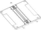
示例性地,第一壳体200靠近转动机构100的一侧设有第一安装槽210,第二壳体300靠近转动机构100的一侧设有第二安装槽310,第二安装槽210和第二安装槽310围设形成能够容置转动机构100的安装空间。转动机构100容置于安装空间,且与第一壳体200和第二壳体300均连接。Exemplarily, the side of the
本申请的实施例中,第一壳体200与第二壳体300能够相对展开至展平状态,以使电子设备2000处于展平状态。示例性地,第一壳体200与第二壳体300处于展平状态时,两者之间的夹角可以大致呈180°设置(也允许存在少许偏差,例如175°、178°或者185°)。第一壳体200与第二壳体300也能够相对折叠至闭合状态,以使电子设备2000处于闭合状态。示例性地,第一壳体200与第二壳体300处于闭合状态时,两者能够完全合拢至相互平行(也允许存在少许偏差)。第一壳体200与第二壳体300还能够相对转动而彼此靠近(折叠)或彼此远离(展开)至中间状态,以使电子设备2000处于中间状态,其中,中间状态可以为展平状态与闭合状态之间的任意状态。示例性地,第一壳体200与第二壳体300处于中间状态时,两者之间的夹角可以呈现135°、90°或45°。In the embodiment of the present application, the
由此,电子设备2000可以通过转动机构100的驱使,在展平状态与闭合状态之间相互切换,并在展平状态和闭合状态保持。Thus, the
而电子设备2000处于展平状态时,电子设备2000的平面尺寸较大,柔性显示屏1100被展平而处于展平状态。此时,柔性显示屏1100能够进行全屏显示,故而电子设备2000具有较大的显示面积,能够呈现大屏显示的效果,提高用户的使用体验。而电子设备2000处于折叠状态时,电子设备2000的平面尺寸较小,便于用户收纳和携带。举例而言,电子设备2000可采用折叠装置1000实现柔性显示屏1100内折,此时,柔性显示屏1100可夹设于第一壳体200和第二壳体300之间,即,柔性显示屏1100可位于折叠装置1000内侧而呈现被折叠装置1000包裹的状态。或者,电子设备2000可采用折叠装置1000实现柔性显示屏1100外折,此时,柔性显示屏1100可作为电子设备2000的外观结构而暴露在外部,即,柔性显示屏1100可位于折叠装置1000外侧而呈现包裹折叠装置1000的状态。When the
具体而言,请再次参阅图2,柔性显示屏1100包括依次连接的第一非折弯部1110、折弯部1120及第二非折弯部1130,第一非折弯部1110固定于第一壳体200,第二非折弯部1130固定于第二壳体300。在第一壳体200与第二壳体300相对折叠和相对展开的过程中,折弯部1120发生形变。示例性地,柔性显示屏1100可以为有机发光二极管(organic light-emitting diode,OLED)显示屏,有源矩阵有机发光二极体或主动矩阵有机发光二极体(active-matrix organic light-emitting diode,AMOLED)显示屏,迷你发光二极管(miniorganic light-emitting diode)显示屏,微型发光二极管(micro organic light-emitting diode)显示屏,微型有机发光二极管(micro organic light-emitting diode)显示屏,量子点发光二极管(quantum dot light emitting diodes,QLED)显示屏。Specifically, please refer to FIG. 2 again, the
本申请的实施例中,电子设备2000通过优化折叠装置1000的转动机构100,能够使得转动结构具有主动带动运动支撑板运动的主动带动结构,从而使运动支撑板在运动过程中可以获得足够的推动力而进行流畅、稳定地运动,可靠性强,有利于提高用户的使用体验,具体将在下文进行说明。In the embodiment of the present application, by optimizing the
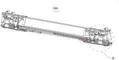
请结合参阅图3、图4和图5,转动机构100包括中壳10、运动连接组件20、第一支撑板30和第二支撑板40。Please refer to FIG. 3 , FIG. 4 and FIG. 5 , the
可以理解的是,在柔性显示屏延伸方向上,第一壳体200、第一支撑板30、中壳10、第二支撑板40和第二壳体300依次排布。示例性地,第一支撑板30和第二支撑板40对称分布在中壳10的两侧,第一壳体200和第二壳体300对称分布在中壳10的两侧。但应当理解,对称分布,指的是位置上的对称分布,并不是指两个支撑板和两个壳体的形状结构完全相同,它们的结构可以相同,也可以不同。It can be understood that, in the extending direction of the flexible display screen, the
由此,第一壳体200、第一支撑板30、中壳10、第二支撑板40和第二壳体300能够在折叠装置1000的折叠态、中间态和闭合态均起到共同支撑柔性显示屏1100的作用,可靠性强。Thus, the
中壳10能够在第一壳体200和第二壳体300相对折叠和相对展开的过程中,维持静止状态。换言之,在第一壳体200与第二壳体300相对折叠和相对展开的过程中,中壳10能够保持自身的位置不发生改变,即中壳10相对静止,而第一壳体200与第二壳体300均可相对于中壳10发生转动,且当第一壳体200与第二壳体300相对折叠至闭合状态时,中壳10位于第一壳体200和第二壳体300之间。The
运动连接组件20连接第一壳体200、中壳10和第二壳体300。示例性地,运动连接组件20的数量为两个,两个运动连接组件20在中壳10的长度方向(也即电子设备2000的宽度方向)上间隔排列。两个运动连接组件20可分别连接于中壳10的顶部和底部。或者,运动连接组件20的数量为一个,一个运动连接组件20可连接于中壳10的中部,且与第一壳体200的中部和第二壳体300的中部连接。应当理解,转动机构100的结构可以有多种组合和变形方式,本申请实施例对此不做严格限定。The
第一支撑板30位于中壳10朝向第一壳体200的一侧,第一支撑板30连接运动连接组件20。第二支撑板40位于中壳10朝向第二壳体300的一侧,第二支撑板40连接运动连接组件20。由此,第一支撑板30和第二支撑板40可位于两个运动连接组件20的同侧且均与两个运动连接组件20连接,可随两个运动连接组件20的运动而运动,以与第一壳体200、中壳10和第二壳体300配合支撑或容纳柔性显示屏1100。The
请结合参阅图6和图7,具体而言,电子设备2000处于展平状态时,第一壳体200、第一支撑板30、中壳10、第二支撑板40和第二壳体300齐平而共同支撑柔性显示屏1100,使得柔性显示屏1100更为平整,不易因外力触摸而发生损坏,提高柔性显示屏1100的可靠性。电子设备2000处于闭合状态时,第一壳体200与第二壳体300能够完全合拢至相互平行,从而使第一壳体200、第一支撑板30、中壳10、第二支撑板40和第二壳体300共同形成容纳柔性显示屏1100的收容空间,从而能够与柔性显示屏1100的理想闭合形态保持一致,对闭合形态的柔性显示屏1100提供更为优异的支撑性能。应当理解,柔性显示屏1100可贴合于第一壳体200、第一支撑板30、中壳10、第二支撑板40和第二壳体300上。Please refer to FIG. 6 and FIG. 7 in conjunction. Specifically, when the
以下将对运动连接组件20的具体结构和连接关系进行详细说明。The specific structure and connection relationship of the
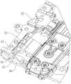
请结合参阅图5、图8和图9,运动连接组件20组件包括第一固定架21、第一传动臂22、第一转动臂23、第二固定架24、第二传动臂25和第二转动臂26。Please refer to FIG. 5 , FIG. 8 and FIG. 9 , the
第一固定架21可设有多个紧固孔,可通过多个紧固件与多个紧固孔的一一对应关系,将第一固定架21固定于第一壳体200,即,转动机构100通过第一固定架21实现与第一壳体200的连接关系。The
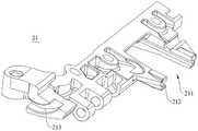
请结合参阅图5、图9和图10,第一固定架21还可设有第一滑槽211,第一滑槽211可用以实现与第一传动臂22上相应结构的滑动连接。示例性地,第一滑槽211具有两个相对设置的侧壁,两个相对设置的侧壁凹陷而共同形成第一滑槽211的导向空间212。也即为,第一滑槽211的侧壁可具有凹陷的导向空间212,用以引导第一传动臂22上相应结构的滑动方向,使得第一固定架21与第一传动臂22之间的相对滑动动作更易实现,控制精度更高。Please refer to FIG. 5 , FIG. 9 and FIG. 10 , the
第一固定架21的端部设有第一转动槽213,第一转动槽213呈弧形,第一转动槽213能够与第一支撑板30上相应结构实现转动配合,以形成第一固定架21和第一支撑板30之间的虚拟轴转动连接,保证第一传动臂22上相应结构在转动时不发生移位,以确保转动机构100开合时的稳定性。The end of the
可以理解的是,第一固定架21能够相对中壳10转动,且第一固定架21还固定于第一壳体200。由此,第一固定架21的运动可带动第一壳体200的运动。示例性地,第一固定架21相对中壳10转动时,会带动第一壳体200一起相对中壳10转动。It can be understood that the
请结合参阅图5、图11和图12,第二固定架24可设有多个紧固孔,可通过多个紧固件与多个紧固孔的一一对应关系,将第二固定架24固定于第二壳体300,即,转动机构100通过第二固定架24实现与第二壳体300的连接关系。Please refer to FIG. 5 , FIG. 11 and FIG. 12 , the
而第二固定架24还可设有第二滑槽241,第二滑槽241可用以实现与第二传动臂25上相应结构的滑动连接。示例性地,第二滑槽241具有两个相对设置的侧壁,两个相对设置的侧壁凹陷而共同形成第二滑槽241的导向空间242。也即为,第二滑槽241的侧壁可具有凹陷的导向空间242,用以引导第二传动臂25上相应结构的滑动方向,使得第二固定架24与第二传动臂25之间的相对滑动动作更易实现,控制精度更高。The
第二固定架24的端部设有第二转动槽243,第二转动槽243呈弧形,第二转动槽243能够与第二支撑板40上相应结构实现转动配合,以形成第二固定架24和第二支撑板40之间的虚拟轴转动连接,保证第二传动臂25上相应结构在转动时不发生移位,以确保转动机构100开合时的稳定性。The end of the
可以理解的是,第二固定架24能够相对中壳10转动,且第二固定架24还固定于第二壳体300。由此,第二固定架24的运动可带动第二壳体300的运动。示例性地,第二固定架24相对中壳10转动时,会带动第二壳体300一起相对中壳10转动。It can be understood that the
基于上述描述,当第一固定架21和第二固定架24均相对中壳10转动而彼此靠近或彼此远离时,第一壳体200能够被第一固定架21带动而相对中壳10转动,第二壳体300能够被第二固定架24带动而相对中壳10转动,从而实现第一壳体200和第二壳体300的相对折叠或相对展开。Based on the above description, when both the
请再次参阅图5,本申请的实施例中,第一固定架21能够通过第一转动臂23实现与中壳10的转动连接。具体而言,第一转动臂23的一端与第一固定架21连接,且第一转动臂23的一端与第一固定架21能够相对转动。而第一转动臂23的另一端与中壳10连接,且第一转动臂23的另一端能够相对中壳10转动。换言之,第一转动臂23的一端与第一固定架21转动连接,第一转动臂23的另一端与中壳10转动连接。Referring to FIG. 5 again, in the embodiment of the present application, the
示例性地,第一转动臂23的一端可通过真实轴与第一固定架21转动连接。第一转动臂23的另一端可设有弧形臂,中壳10可设有弧形槽,弧形臂安装于弧形槽中,通过两者的相对运动,使第一转动臂23与中壳10之间通过虚拟轴转动连接。或者,第一转动臂23和中壳10之间也可通过真实轴转动连接,本申请实施例对此不做严格限定。Exemplarily, one end of the first
请结合参阅图13和图14,一种可能的实施方式中,转动机构100还包括第一转动辅助组件50,第一转动辅助组件50包括第二轴体51和第一弹性件52,第一转动臂23通过第二轴体51转动连接至第一固定架21,第一弹性件52套设于第二轴体51且弹性抵持在第一固定架21和第一支撑板30之间。Please refer to FIG. 13 and FIG. 14 , in a possible implementation manner, the
可以理解的是,转动机构100内的各个具有运动配合关系的零件的连接处均会留有运动间隙。此运动间隙会使得第一支撑板30和第二支撑板40在相对中壳10进行转动过程中会产生角度偏差,从而导致折叠装置1000处于闭合状态时,第一支撑板30和第二支撑板40之间的夹角达不到设计所需的角度。例如第一支撑板30和第二支撑板40之间的夹角可能会相较于设计所需的角度而偏小,从而对柔性显示屏1100造成挤压,使得柔性显示屏1100的局部应力增大,导致柔性显示屏1100更易破损。由此,增加第一转动辅助组件50,能够将因零件间的运动间隙而造成第一支撑板30和第二支撑板40之间夹角达不到设计所需的角度的可能性降低到最小,能够使第一支撑板30和第二支撑板40之间的夹角处于设计所需的最优角度。It can be understood that, there will be movement gaps at the joints of the parts in the
示例性地,第一弹性件52为扭簧,扭簧具有两个自由端,扭簧的一个自由端与第一固定架21连接,且相对第一固定架21的位置固定不变。扭簧的另一个自由端与第一支撑板30连接,且相对第一支撑板30的位置固定不变。换言之,扭簧的一个自由端固定连接至第一固定架21,扭簧的另一个自由端固定连接至第一支撑板30。举例而言,扭簧与第一固定架21固定的自由端可通过粘接、卡接等方式与第一固定架21固定,扭簧与第一支撑板30固定的自由端可通过卡入第一支撑板30上相应的锁紧结构而与第一支撑板30固定。但应当理解,扭簧与第一固定架21和第一支撑板30固定的方式可根据实际需求进行设计,本申请的实施例对此不做严格限制。Exemplarily, the first
由此,扭簧的扭力能够作用在第一支撑板30上,从而给第一支撑板30增加一个朝向第一固定架21方向的拉力。在折叠装置1000的闭合状态,此拉力能够消除各零件的运动间隙造成的角度偏差,使第一支撑板30的运动达到设计角度,从而使得第一支撑板30与第二支撑板40之间的夹角满足设计需求,结构简单且性能优异。Therefore, the torsion force of the torsion spring can act on the
请结合参阅图5、图11和图12,第二固定架24能够通过第二转动臂26实现与中壳10的转动连接。具体而言,第二转动臂26的一端与第二固定架24连接,且第二转动臂26的一端与第二固定架24能够相对转动。而第二转动臂26的另一端与中壳10连接,且第二转动臂26的另一端能够相对中壳10转动。换言之,第二转动臂26的一端与第二固定架24转动连接。第二转动臂26的另一端与中壳10转动连接。Please refer to FIG. 5 , FIG. 11 and FIG. 12 , the
示例性地,第二转动臂26的一端可通过真实轴与第二固定架24转动连接。第二转动臂26的另一端可设有弧形臂,中壳10可设有弧形槽,弧形臂安装于弧形槽中,通过两者的相对运动,使第二转动臂26与中壳10之间通过虚拟轴转动连接。或者,第二转动臂26和中壳10之间也可通过真实轴转动连接,本申请实施例对此不做严格限定。Exemplarily, one end of the second
可以理解的是,第二转动臂26和第二固定架24之间的具体连接形态可参照前述的第一转动臂23和第一固定架21之间的第一转动辅助组件50,在此不再赘述。It can be understood that, for the specific connection form between the second
由此,能够形成“第一转动臂23-第一固定架21-第一壳体200”以及“第二转动臂26-第二固定架24-第二壳体300”的转动连接关系,使得第一固定架21和第二固定架24能够分别通过第一转动臂23和第二转动臂26的带动而相对中壳10转动,以实现第一壳体200和第二壳体300的相对折叠和相对展开。In this way, the rotational connection relationship of "the first rotating arm 23 - the first fixing frame 21 - the
本申请的实施例中,在第一固定架21被第一转动臂23带动相对中壳10转动时,第一传动臂22能够相对第一固定架21滑动。且在第二固定架24被第二转动臂26带动相对中壳10转动时,第二传动臂25能够相对第二固定架24滑动。以下将对第一传动臂22能够相对第一固定架21滑动,及第二传动臂25能够相对第二固定架24滑动的滑动原理进行说明。In the embodiment of the present application, when the first fixed
请结合参阅图5、图11和图12,第一传动臂22包括滑动端221和转动端222,第一传动臂22的滑动端221滑动连接第一固定架21,第一传动臂22的转动端222转动连接中壳10。示例性地,第一传动臂22的转动端222可设有弧形臂,中壳10可设有弧形槽,弧形臂安装于弧形槽中,通过两者的相对运动(例如滑动),使第一传动臂22与中壳10之间通过虚拟轴转动连接。或者,第一传动臂22和中壳10之间也可通过真实轴转动连接,本申请实施例对此不做严格限定。5, 11 and 12, the
由此,第一传动臂22能够相对中壳10转动。换言之,第一传动臂22具有转动中心,且第一传动臂22的转动中心为第一轴线C1。第一传动臂22的转动中心(第一轴线C1)即为第一传动臂22与中壳10相对转动的转动中心,可理解为能够使第一传动臂22绕其相对中壳10做角度范围在0°~90°范围内的转动运动的直线。第一转动臂23也能够相对中壳10转动。换言之,第一转动臂23具有转动中心,且第一转动臂23的转动中心为第二轴线C2。第一转动臂23的转动中心(第二轴线C2)即为第一转动臂23与中壳10相对转动的转动中心,可理解为能够使第一转动臂23绕其相对中壳10做角度范围在0°~90°范围内的转动运动的直线。Thus, the
而第一轴线C1相对于第二轴线C2更远离中壳10靠近第一壳体200的边缘,其中,中壳10靠近第一壳体200的边缘可理解为中壳10靠近第一壳体200一侧的长边的边缘,也即为中壳10边缘中位于电子设备2000的宽度方向且朝向第一壳体200一侧的边缘。换言之,第一轴线C1和第二轴线C2之间具有距离差。The first axis C1 is farther away from the edge of the
也即为,第一轴线C1和第二轴线C2不共线,且两者之间因具有距离差而彼此错位设置。基于此,当第一转动臂23和第一传动臂22相对中壳10转动时,第一转动臂23相较于第一传动臂22会超前转动,第一传动臂22相较于第一转动臂23会滞后转动。That is, the first axis C1 and the second axis C2 are not collinear, and the two are offset from each other due to a distance difference therebetween. Based on this, when the first
由此,利用第一轴线C1和第二轴线C2错位设置,而使两者之间的转动产生相位差动的相位差动原理,使得第一传动臂22和第一转动臂23的转动过程中,第一传动臂22与第一固定架21之间能够发生相对滑动。Therefore, using the phase difference principle that the first axis C1 and the second axis C2 are staggered, and the rotation between the two generates a phase difference, so that the
请结合参阅图5、图11和图12,具体而言,第一传动臂22的滑动端221包括第一滑动主体223和第一轴体224。第一滑动主体223包括正面225、背面226以及连接正面224和背面225的周侧面227,第一滑动主体223的正面225、背面226和周侧面227彼此连接而形成第一滑动主体223的外表面。第一滑动主体223的正面225和背面226均设有第一凸缘228,第一凸缘228连接于第一滑槽211的导向空间212,且第一凸缘228能够相对第一滑槽211滑动。Please refer to FIG. 5 , FIG. 11 and FIG. 12 , specifically, the sliding
由此,第一滑动主体223与第一滑槽211能够形成滑块滑槽结构,从而通过第一滑动主体223的第一凸缘228与第一滑槽211的导向空间212的配合,使得第一滑动主体223与第一滑槽211的相对滑动动作更易实现,控制精度更高。Therefore, the first sliding
本申请的实施例中,第一滑动主体223不仅与第一固定架21连接,第一滑动主体223还与第一支撑板30连接。具体而言,第一滑动主体223的周侧面227向内凹陷形成第一凹陷区229,从而使得第一滑动主体223呈现“U”形。而第一轴体224的一端连接于第一凹陷区229的一侧,第一轴体224的另一端连接于第一凹陷区229的另一侧。In the embodiment of the present application, the first sliding
由此,第一轴体224可大体位于第一凹陷区229,又因第一轴体224还可与第一支撑板30的相应结构连接。换言之,第一滑动主体223可通过第一轴体224与第一支撑板30连接。也即为,第一传动臂22可通过第一轴体224与第一支撑板30连接。从而使得第一凹陷区229不仅能够收容第一轴体224,也可收容第一支撑板30的部分结构,进而能够为第一轴体224与第一滑动主体223的连接以及第一轴体224与第一支撑板30的连接提供便利,节省转动机构100所占用的空间大小,有利于实现折叠装置1000和应用折叠装置1000的电子设备2000的轻薄化。Therefore, the
请结合参阅图5、图11和图12,第二传动臂25包括滑动端251和转动端252,第二传动臂25的滑动端251滑动连接第二固定架24,第二传动臂25的转动端252转动连接中壳10。示例性地,第二传动臂25的转动端252可设有弧形臂,中壳10可设有弧形槽,弧形臂安装于弧形槽中,通过两者的相对运动(例如滑动),使第二传动臂25与中壳10之间通过虚拟轴转动连接。或者,第二传动臂25和中壳10之间也可通过真实轴转动连接,本申请实施例对此不做严格限定。5, 11 and 12, the
由此,第二传动臂25能够相对中壳10转动。换言之,第二传动臂25具有转动中心,且第二传动臂25的转动中心为第三轴线C3。第二传动臂25的转动中心(第三轴线C3)即为第二传动臂25与中壳10相对转动的转动中心,可理解为能够使第二传动臂25绕其相对中壳10做角度范围在0°~90°范围内的转动运动的直线。第二转动臂26也能够相对中壳10转动。换言之,第二转动臂26具有转动中心,且第二转动臂26的转动中心为第四轴线C4。第二转动臂26的转动中心(第四轴线C4)即为第二转动臂26与中壳10相对转动的转动中心,可理解为能够使第二转动臂26绕其相对中壳10做角度范围在0°~90°范围内的转动运动的直线。Thus, the
而第三轴线C3相对于第四轴线C4更远离中壳10靠近第二壳体300的边缘,其中,中壳10靠近第二壳体300的边缘可理解为中壳10靠近第二壳体300一侧的长边的边缘,也即为中壳10边缘中位于电子设备2000的宽度方向且朝向第二壳体300一侧的边缘。换言之,第三轴线C3和第四轴线C4之间具有距离差。The third axis C3 is farther away from the edge of the
也即为,第三轴线C3和第四轴线C4不共线,且两者之间因具有距离差而彼此错位设置。基于此,当第二转动臂26和第二传动臂25相对中壳10转动时,第二转动臂26相较于第二传动臂25会超前转动,第二传动臂25相较于第二转动臂26会滞后转动。That is, the third axis C3 and the fourth axis C4 are not collinear, and the two are offset from each other due to a distance difference therebetween. Based on this, when the second
由此,利用第三轴线C3和第四轴线C4错位设置,而使两者之间的转动产生相位差动的相位差动原理,使得第二传动臂25和第二转动臂26的转动过程中,第二传动臂25与第二固定架24之间能够发生相对滑动。Therefore, using the phase difference principle of the dislocation of the third axis C3 and the fourth axis C4, the rotation between the two generates a phase difference, so that the
具体而言,第二传动臂25的滑动端251包括第二滑动主体253和第三轴体254。第二滑动主体253包括正面、背面以及连接正面和背面的周侧面,第二滑动主体253的正面、背面和周侧面彼此连接而形成第二滑动主体253的外表面。第二滑动主体253的正面和背面均设有第二凸缘,第二凸缘连接于第二滑槽241的导向空间242,且第二凸缘能够相对第二滑槽241滑动。Specifically, the sliding
由此,第二滑动主体253与第二滑槽241能够形成滑块滑槽结构,从而通过第二滑动主体253的第二凸缘与第二滑槽241的导向空间242的配合,使得第二滑动主体253与第二滑槽241的相对滑动动作更易实现,控制精度更高。Therefore, the second sliding
本申请的实施例中,第二滑动主体253不仅与第二固定架24连接,第二滑动主体253还与第二支撑板40连接。具体而言,第二滑动主体253的周侧面向内凹陷形成第二凹陷区,从而使得第二滑动主体253呈现“U”形。而第三轴体254的一端连接于第二凹陷区的一侧,第三轴体254的另一端连接于第二凹陷区的另一侧。In the embodiment of the present application, the second sliding
由此,第三轴体254可大体位于第二凹陷区,又因第三轴体254还可与第二支撑板40的相应结构连接。换言之,第二滑动主体253可通过第三轴体254与第二支撑板40连接。也即为,第二传动臂25可通过第三轴体254与第二支撑板40连接。从而使得第二凹陷区不仅能够收容第三轴体254,也可收容第二支撑板40的部分结构,进而能够为第三轴体254与第二滑动主体253的连接以及第三轴体254与第二支撑板40的连接提供便利,节省转动机构100所占用的空间大小,有利于实现折叠装置1000和应用折叠装置1000的电子设备2000的轻薄化。Therefore, the
基于上述描述,应当理解,第一传动臂22与中壳10转动连接、与第一固定架21滑动连接,从而形成了连杆滑块结构。而第一转动臂23与中壳10转动连接、与第一固定架21转动连接,从而形成了连杆结构。第二传动臂25与中壳10转动连接、与第二固定架24滑动连接,从而形成了连杆滑块结构。而第二转动臂26与中壳10转动连接、与第二固定架24转动连接,从而形成了连杆结构。Based on the above description, it should be understood that the
由此,转动机构100能够通过连杆滑块结构和连杆结构实现第一固定架21和第二固定架24与中壳10之间的连接。此架构下,转动机构100具有较少的零件数量,配合关系及配合位置简单,组成部件易制作和组装,有利于实现量产。另外,第一固定架21还联动第一壳体200,第二固定架24还联动第二壳体300,从而使得转动机构100整体具有较佳的机构抗拉能力和机构抗挤能力。Therefore, the
另外,转动机构100通过第一传动臂22和第一转动臂23共同控制第一固定架21和第一壳体200的运动轨迹、通过第二传动臂25和第二转动臂26共同控制第二固定架24和第二壳体300的运动轨迹。从而能够在第一壳体200与第二壳体300相对折叠的过程中,使第一固定架21带动第一壳体200向靠近中壳10的方向移动、第二固定架24带动第二壳体300向靠近中壳10的方向移动。在第一壳体200与第二壳体300相对展开的过程中,使第一固定架21带动第一壳体200向远离中壳10的方向移动、第二固定架24带动第二壳体300向远离中壳10的方向移动。也即,转动机构100能够实现折叠装置1000在展平状态向闭合状态变化的过程中的壳体内拉运动、和折叠装置1000在闭合状态向展平状态变化的过程中的壳体外推运动,使得折叠装置1000在展开或折叠的过程中,能够实现柔性显示屏1100的变形运动,从而降低拉扯或挤压柔性显示屏1100的风险,以保护柔性显示屏1100,提高柔性显示屏1100的可靠性,使得柔性显示屏1100和电子设备2000具有较长的使用寿命。In addition, the
请结合参阅图5、图11和图12,本申请的实施例中,第一支撑板30活动连接第一传动臂22的滑动端221,第一壳体200与第二壳体300相对折叠或相对展开的过程中,第一支撑板30与第一传动臂22的滑动端221相对滑动且转动。由此,第一支撑板30能够在第一传动臂22与第一固定架21发生相对滑动时,被第一传动臂22带动而跟随运动。也即为,第一支撑板30能够通过第一传动臂22相对第一固定架21的滑动,而被第一传动臂22带动相对中壳10转动,以使第一壳体100、第一支撑板30和中壳10在展平状态和折叠状态之间切换。Please refer to FIG. 5 , FIG. 11 and FIG. 12 , in the embodiment of the present application, the
需说明的是,展平状态可理解为第一壳体200、第一支撑板30未相对中壳10发生转动而使第一壳体200、第一支撑板30和中壳10齐平而共同支撑柔性显示屏1100。示例性地,处于展平状态时,第一壳体200、第一支撑板30和中壳10可呈直线状排布。折叠状态可理解为第一壳体200和第一支撑板30相对中壳10发生转动而使第一壳体200和第一支撑板30与中壳10呈夹角设置而形成收容柔性显示屏1100的收容空间。示例性地,处于折叠状态时,第一壳体200、第一支撑板30和中壳10可呈现弧形排布。It should be noted that the flattened state can be understood as the
第二支撑板40活动连接第二传动臂25的滑动端251,第一壳体200与第二壳体300相对折叠或相对展开的过程中,第二支撑板40与第二传动臂25的滑动端251相对滑动且转动。由此,第二支撑板40能够在第二传动臂25与第二固定架24发生相对滑动时,被第二传动臂25带动而跟随运动。也即为,第二支撑板40能够通过第二传动臂25相对第二固定架24的滑动,而被第二传动臂25带动相对中壳10转动,以使第二壳体300、第二支撑板40和中壳10在展平状态和折叠状态之间切换。The
需说明的是,展平状态可理解为第二壳体300、第二支撑板40未相对中壳10发生转动而使第二壳体300、第二支撑板40和中壳10齐平而共同支撑柔性显示屏1100。示例性地,处于展平状态时,第二壳体300、第二支撑板40和中壳10可呈直线状排布。折叠状态可理解为第二壳体300和第二支撑板40相对中壳10发生转动而使第二壳体300和第二支撑板40与中壳10呈夹角设置而形成收容柔性显示屏1100的收容空间。示例性地,处于折叠状态时,第二壳体300、第二支撑板40和中壳10可呈现弧形排布。It should be noted that the flattened state can be understood as the fact that the
基于此,第一传动臂22能够作为第一支撑板30的主动带动结构,在第一传动臂22相对第一固定架21滑动时,使第一支撑板30跟随运动。换言之,第一传动臂22可以直接驱使第一支撑板30运动,从而使第一支撑板30能够具有足够的推力而进行稳定、流畅的运动,将第一支撑板30运动过程中出现卡涩、卡死的可能性降低到最小,可靠性强。第二传动臂25能够作为第二支撑板40的主动带动结构,在第一传动臂22相对第二固定架24滑动时,使第二支撑板40跟随运动。换言之,第二传动臂25可直接驱使第二支撑板40运动,从而使第二支撑板40能够具有足够的推力而进行稳定、流畅的运动,将第二支撑板40运动过程中出现卡涩、卡死的可能性降低到最小,可靠性强。Based on this, the
应当理解,第一支撑板30能够随第一传动臂22运动,第二支撑板40能够随第二传动臂25运动。一方面,能够使得第一支撑板30和第二支撑板40的运动过程的控制精度高、回差小。另一方面,能够更好地满足柔性显示屏1100的支撑需求,从而在折叠装置1000处于展平状态、中间状态及闭合状态时,均能够与中壳10共同形成对柔性显示屏1100的折弯部1120的强力支撑,使得柔性显示屏1100不易在外力作用下损坏,以提高柔性显示屏1100的可靠性,延长柔性显示屏1100和电子设备2000的使用寿命。It should be understood that the
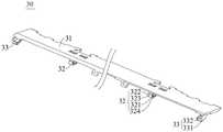
请参阅图15,第一支撑板30包括第一板体31、第一导向结构32和第一转动结构33。第一导向结构32和第一转动结构33凸设于第一板体31,且两者均位于第一板体31朝向中壳10的同侧,第一转动结构33相对于第一导向结构32更靠近第一板体31的端部。第一支撑板30通过第一导向结构32滑动连接第一传动臂22,且通过第一转动结构33转动连接第一固定架21。Referring to FIG. 15 , the
示例性地,第一导向结构32和第一转动结构33的数量均为两个,且一个第一导向结构32和一个第一转动结构33间隔排列于第一板体31的顶部,另一个第一导向结构32和另一个第一转动结构33间隔排列于第一板体31的底部。应当理解,第一导向结构32和第一转动结构33的数量及排布关系可以有多种组合和变形方式,本申请实施例对此不做严格限定。Exemplarily, the number of the
一种可能的实施方式中,第一支撑板30可以为一体成型的结构件,一体成型所形成的第一支撑板30组装工序少,有利于节省生产时间和成本。In a possible implementation, the
请结合参阅图5、图11和图12,第一导向结构32连接于第一凹陷区229,由此,第一凹陷区229不仅能够收容第一轴体224,也可收容第一支撑板30的第一导向结构32,进而能够为第一轴体224与第一导向结构32的连接提供便利,节省转动机构100所占用的空间大小,有利于实现折叠装置1000和应用折叠装置1000的电子设备2000的轻薄化。Please refer to FIG. 5 , FIG. 11 and FIG. 12 , the
另外,第一导向结构32与第一滑动主体223能够相对滑动。即,第一支撑板30与第一传动臂22能够相对滑动。由此,第一支撑板30能够跟随第一传动臂22运动,也即,第一支撑板30能够通过第一传动臂22相对第一固定架21的滑动,而被第一传动臂22带动相对中壳10转动。从而使得第一支撑板30因被第一传动臂22带动而始终具有足够的驱动力,能够在运动过程中具有良好的运动流畅度,使得第一支撑板30能够在第一壳体200和第二壳体300相对折叠或相对展开的过程中运动到位,有利于提高对柔性显示屏1100的保护性能。In addition, the
请再次参阅图15,第一导向结构32包括正面321、背面322以及连接正面321和背面322的周侧面323,第一导向结构32的正面321、背面322和周侧面323彼此连接而形成第一导向结构32的外表面。示例性地,第一导向结构32呈月牙状。Referring to FIG. 15 again, the
第一导向结构32设有第一轨迹槽324,第一轨迹槽324贯穿第一导向结构32的正面321和背面322,且第一轨迹槽324未贯穿第一导向结构32的周侧面323,第一轨迹槽324用以供第一轴体224在其内滑动。The
由此,第一轨迹槽324能够形成封闭结构,且由于其封闭特性,能够使得第一轴体224仅能在其限制出的活动空间内往复滑动,起到限位第一轴体224的作用,能够有效防止第一轴体224意外脱离第一轨迹槽324。Therefore, the
具体而言,第一轴体224的一端连接于第一凹陷区229的一侧,第一轴体224穿过第一轨迹槽324,第一轴体224的另一端连接于第一凹陷区229的另一侧,第一轴体224能够在第一轨迹槽324滑动。也即为,第一轴体224穿设于第一轨迹槽324内,且能够沿第一轨迹槽324的延伸轨迹滑动。换言之,第一传动臂22的滑动端221与第一支撑板30能够相对滑动。Specifically, one end of the
可以理解的是,在第一传动臂22相对第一固定架21的滑动过程中,第一轴体224能够在第一轨迹槽324内滑动,以使第一支撑板30跟随运动。即,在第一壳体200与第二壳体300相对折叠和相对展开的过程中,第一传动臂22能够带动第一支撑板30相对中壳10转动。It can be understood that, during the sliding process of the
由此,通过设置第一轨迹槽324,能够将第一轴体224在第一轨迹槽324内的滑动运动转化为第一传动臂22和第一支撑板30之间的相对运动,实现第一传动臂22主动带动第一支撑板30运动的主动带动功能,多元化第一传动臂22的使用性能,实用性强,应用范围广泛。Therefore, by setting the
本申请的实施例中,第一轨迹槽324的延伸路径的形状可根据柔性显示屏1100进行折叠和展开运动所需要的轨迹形态和/或第一支撑板30的实际运动需求而调整,以实现对柔性显示屏1100的运动轨迹的可调节功能。换言之,第一轨迹槽324的延伸路径可调。也即,第一轨迹槽324的轨迹可进行调整。In the embodiment of the present application, the shape of the extension path of the
一种可能的实施方式中,第一轨迹槽324的延伸路径为弧形,从而使得第一轨迹槽324的形状呈弧形。由此,能够通过调整第一轨迹槽324的弧形的弧度,一方面,能够直接控制第一支撑板30的运动轨迹,使得第一支撑板30的运动过程的控制精度高、回差小,避免第一支撑板30在跟随运动到某些角度时会对柔性显示屏1100造成拉扯、挤压的问题发生,有效改善柔性显示屏1100的屏幕应力。另一方面,能够间接对柔性显示屏1100的运动轨迹进行调整,使得第一轨迹槽324的弧形的弧度能够更佳的适应柔性显示屏1100的运动轨迹,实现对柔性显示屏1100的运动轨迹的可调节功能。In a possible implementation, the extension path of the
另一种可能的实施方式中,第一轨迹槽324的延伸路径为直线形,从而使得第一轨迹槽324的形状呈线形。In another possible implementation, the extension path of the
由此,可对第一轨迹槽324的延伸路径进行设计,使得第一壳体200和第二壳体300相对折叠和相对展开的过程中,第一支撑板30的中间运动过程即运动轨迹可设计,从而能够控制柔性显示屏1100在此过程中的运动轨迹,避免柔性显示屏1100局部应力过大的问题发生,有效改善柔性显示屏1100的屏幕应力。应当理解,第一轨迹槽324的延伸路径可不局限于上述的弧形或直线形,还可以是曲线、直线、折线中一种或多种的组合,本申请的实施例对此不做严格限定。Therefore, the extension path of the
请结合参阅图5、图11、图12和图15,第一转动结构33与第一导向结构32位于第一板体31的同侧,第一转动结构33呈弧形且安装于第一转动槽213,通过第一转动结构33和第一转动槽213的配合使第一支撑板30与第一固定架21转动连接。Please refer to FIG. 5, FIG. 11, FIG. 12 and FIG. 15. The first
由此,通过第一转动结构33和第一转动槽213的相对运动,使第一支撑板30与第一固定架21之间通过虚拟轴转动连接。此架构下,转动连接结构简单,占用空间小,有利于减小转动机构100的厚度,使得折叠装置1000及电子设备2000更易实现轻薄化。Therefore, through the relative movement of the first
请参阅图16,可以理解的是,柔性显示屏1100贴合在第一壳体200和第一支撑板30上,第一转动结构33的转动中心E1位于柔性显示屏1100,其中,转动中心可理解为能够使第一转动结构33绕其做转动运动的直线或轴线。Referring to FIG. 16 , it can be understood that the
由此,第一支撑板30的转动中心(也即第一转动结构33的转动中心)能够位于柔性显示屏1100,从而在第一支撑板30的转动过程中,柔性显示屏1100的长度能够保持恒长,进而保障柔性显示屏1100的弯折过程中屏幕不被拉升或挤压,且能控制此处柔性显示屏1100的弯折半径。从而可以最大程度的降低弯折的过程中对柔性显示屏1100带来的损害,可靠性强。Therefore, the rotation center of the first support plate 30 (that is, the rotation center of the first rotation structure 33 ) can be located at the
示例性地,第一转动结构33的转动中心E1位于柔性显示屏1100的中性层,以使柔性显示屏1100能够保持恒长。应当理解,柔性显示屏1100在弯曲的过程中,柔性显示屏1100的外层受拉伸力,柔性显示屏1100的内层受挤压力。而在柔性显示屏1100的外层和内层的断面上存在一个既不受拉伸力,又不受挤压力的过渡层,该过渡层的应力几乎为零,该过渡层即为柔性显示屏1100的中性层。即柔性显示屏1100的中性层是指当柔性显示屏1100发生弯曲变形时,其内部切向应力为零的所有位置所形成的层。柔性显示屏1100的中性层在弯曲过程中的长度和弯曲前一样,保持不变。Exemplarily, the rotation center E1 of the
需说明的是,图16仅为示意性的描述第一转动结构33的转动中心E1,并非是对各个部件连接位置、具体构造及数量做具体限定。而柔性显示屏1100的内层和外层可根据柔性显示屏1100内折或外折的状态而进行选取,对此不做具体限制。It should be noted that FIG. 16 only schematically describes the rotation center E1 of the
请继续参阅图5、图11、图12和图15,本实施例中,第一转动结构33包括凸设于第一板体31的第一挡板331和第一弧形臂332。第一弧形臂332连接于第一挡板331的一侧,且第一弧形臂332还连接于第一转动槽213内并能在第一转动槽213内滑动。示例性地,第一弧形臂332可呈月牙形。第一挡板331用于支撑第一弧形臂332,以增加第一转动结构33的强度,避免第一弧形臂332在转动过程中因发生断裂、破损等情况而造成转动机构100失效的问题发生。Please continue to refer to FIG. 5 , FIG. 11 , FIG. 12 and FIG. 15 , in this embodiment, the first
一种可能的实施方式中,第一挡板331和第一弧形臂332可以一体成型,一体成型所形成的第一转动结构33组装工序少,有利于节省生产时间和成本。In a possible embodiment, the
可以理解的是,在第一支撑板30被第一传动臂22带动而跟随运动时,第一弧形臂332能够在第一转动槽213内进行转动。第一弧形臂332能够在第一转动槽213内进行转动可理解为第一弧形臂332在第一转动槽213内进行往复滑动,即第一弧形臂332能够在第一转动槽213内由第一转动槽213的一端滑动至第一转动槽213的另一端,再由第一转动槽213的另一端滑动回至第一转动槽213的一端,并重复这一过程。也即为,第一弧形臂332转动连接于第一转动槽213。It can be understood that, when the
由此,通过第一弧形臂332与第一转动槽213的配合,使得第一传动臂22相对第一固定架21发生滑动时,第一传动臂22能够带动第一支撑板30相对中壳10进行转动运动。即,在第一传动臂22的滑动过程中,第一支撑板30可以跟随转动。Therefore, through the cooperation between the first arc-shaped
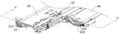
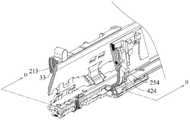
请参阅图17,第二支撑板40包括第二板体41、第二导向结构42和第二转动结构43。第二导向结构42和第二转动结构43凸设于第二板体41,且两者均位于第二板体41朝向中壳10的同侧,第二转动结构43相对于第二导向结构42更靠近第二板体41的端部。第二支撑板40通过第二导向结构42滑动连接第二传动臂25,且通过第二转动结构43转动连接第二固定架24。Referring to FIG. 17 , the
示例性地,第二导向结构42和第二转动结构43的数量均为两个,且一个第二导向结构42和一个第二转动结构43间隔排列于第二板体41的顶部,另一个第二导向结构42和另一个第二转动结构43间隔排列于第二板体41的底部。应当理解,第二导向结构42和第二转动结构43的数量及排布关系可以有多种组合和变形方式,本申请实施例对此不做严格限定。Exemplarily, the number of the
一种可能的实施方式中,第二支撑板40可以为一体成型的结构件,一体成型所形成的第二支撑板40组装工序少,有利于节省生产时间和成本。In a possible embodiment, the
请结合参阅图5、图11和图12,第二导向结构42连接于第二凹陷区,由此,第二凹陷区不仅能够收容第三轴体254,也可收容第二支撑板40的第二导向结构42,进而能够为第三轴体254与第二导向结构42的连接提供便利,节省转动机构100所占用的空间大小,有利于实现折叠装置1000和应用折叠装置1000的电子设备2000的轻薄化。Please refer to FIG. 5 , FIG. 11 and FIG. 12 , the
另外,第二导向结构42与第二滑动主体253能够相对滑动。即,第二支撑板40与第二传动臂25能够相对滑动。由此,第二支撑板40能够跟随第二传动臂25运动,也即,第二支撑板40能够通过第二传动臂25相对第二固定架24的滑动,而被第二传动臂25带动相对中壳10转动。从而使得第二支撑板40因被第二传动臂25带动而始终具有足够的驱动力,能够在运动过程中具有良好的运动流畅度,使得第二支撑板40能够在第二壳体300和第二壳体300相对折叠或相对展开的过程中运动到位,有利于提高对柔性显示屏1100的保护性能。In addition, the
请再次参阅图17,第二导向结构42包括正面421、背面422以及连接正面421和背面422的周侧面423,第二导向结构42的正面421、背面422和周侧面423彼此连接而形成第二导向结构42的外表面。示例性地,第二导向结构42呈月牙状。Referring to FIG. 17 again, the
第二导向结构42设有第二轨迹槽424,第二轨迹槽424贯穿第二导向结构42的正面421和背面422,且第二轨迹槽424未贯穿第二导向结构42的周侧面423,第二轨迹槽424用以供第三轴体254在其内滑动。The
由此,第二轨迹槽424能够形成封闭结构,且由于其封闭特性,能够使得第三轴体254仅能在其限制出的活动空间内往复滑动,起到限位第三轴体254的作用,能够有效防止第三轴体254意外脱离第二轨迹槽424。Therefore, the
具体而言,第三轴体254的一端连接于第二凹陷区的一侧,第三轴体254穿过第二轨迹槽424,第三轴体254的另一端连接于第二凹陷区的另一侧,第三轴体254能够在第二轨迹槽424滑动。也即为,第三轴体254穿设于第二轨迹槽424内,且能够沿第二轨迹槽424的延伸轨迹滑动。换言之,第二传动臂25的滑动端251与第二支撑板40能够相对滑动。Specifically, one end of the
可以理解的是,在第二传动臂25相对第二固定架24的滑动过程中,第三轴体254能够在第二轨迹槽424内滑动,以使第二支撑板40跟随运动。即,在第二壳体300与第二壳体300相对折叠和相对展开的过程中,第二传动臂25能够带动第二支撑板40相对中壳10转动。It can be understood that, during the sliding process of the
由此,通过设置第二轨迹槽424,能够将第三轴体254在第二轨迹槽424内的滑动运动转化为第二传动臂25和第二支撑板40之间的相对运动,实现第二传动臂25主动带动第二支撑板40运动的主动带动功能,多元化第二传动臂25的使用性能,实用性强,应用范围广泛。Therefore, by setting the
本申请的实施例中,第二轨迹槽424的延伸路径的形状可根据柔性显示屏1100进行折叠和展开运动所需要的轨迹形态和/或第二支撑板40的实际运动需求而调整,以实现对柔性显示屏1100的运动轨迹的可调节功能。换言之,第二轨迹槽424的延伸路径可调。也即,第二轨迹槽424的轨迹可进行调整。In the embodiment of the present application, the shape of the extension path of the
一种可能的实施方式中,第二轨迹槽424的延伸路径为弧形,从而使得第二轨迹槽424的形状呈弧形。由此,能够通过调整第二轨迹槽424的弧形的弧度,一方面,能够直接控制第二支撑板40的运动轨迹,使得第二支撑板40的运动过程的控制精度高、回差小,避免第二支撑板40在跟随运动到某些角度时会对柔性显示屏1100造成拉扯、挤压的问题发生,有效改善柔性显示屏1100的屏幕应力。另一方面,能够间接对柔性显示屏1100的运动轨迹进行调整,使得第二轨迹槽424的弧形的弧度能够更佳的适应柔性显示屏1100的运动轨迹,实现对柔性显示屏1100的运动轨迹的可调节功能。In a possible implementation manner, the extending path of the
另一种可能的实施方式中,第二轨迹槽424的延伸路径为直线形,从而使得第二轨迹槽424的形状呈线形。In another possible implementation, the extension path of the
由此,可对第二轨迹槽424的延伸路径进行设计,使得第二壳体300和第二壳体300相对折叠和相对展开的过程中,第二支撑板40的中间运动过程即运动轨迹可设计,从而能够控制柔性显示屏1100在此过程中的运动轨迹,避免柔性显示屏1100局部应力过大的问题发生,有效改善柔性显示屏1100的屏幕应力。应当理解,第二轨迹槽424的延伸路径可不局限于上述的弧形或直线形,还可以是曲线、直线、折线中一种或多种的组合,本申请的实施例对此不做严格限定。Therefore, the extension path of the
请结合参阅图5、图11、图12和图17,第二转动结构43与第二导向结构42位于第二板体41的同侧,第二转动结构43呈弧形且安装于第二转动槽243,通过第二转动结构43和第二转动槽243的配合使第二支撑板40与第二固定架24转动连接。Please refer to FIG. 5 , FIG. 11 , FIG. 12 and FIG. 17 , the second
由此,通过第二转动结构43和第二转动槽243的相对运动,使第二支撑板40与第二固定架24之间通过虚拟轴转动连接。此架构下,转动连接结构简单,占用空间小,有利于减小转动机构100的厚度,使得折叠装置1000及电子设备2000更易实现轻薄化。Therefore, through the relative movement of the second
请参阅图18,可以理解的是,柔性显示屏1100贴合在第二壳体300和第二支撑板40上,第二转动结构43的转动中心E2位于柔性显示屏1100,其中,转动中心可理解为能够使第二转动结构43绕其做转动运动的直线或轴线。Referring to FIG. 18 , it can be understood that the
由此,第二支撑板40的转动中心(也即第二转动结构43的转动中心)能够位于柔性显示屏1100,从而在第一支撑板30的转动过程中,柔性显示屏1100的长度能够保持恒长,进而保障柔性显示屏1100的弯折过程中屏幕不被拉升或挤压,且能控制此处柔性显示屏1100的弯折半径。从而可以最大程度的降低弯折的过程中对柔性显示屏1100带来的损害,可靠性强。Therefore, the rotation center of the second support plate 40 (that is, the rotation center of the second rotation structure 43 ) can be located at the
示例性地,第二转动结构43的转动中心E2位于柔性显示屏1100的中性层,以使柔性显示屏1100能够保持恒长。应当理解,柔性显示屏1100在弯曲的过程中,柔性显示屏1100的外层受拉伸力,柔性显示屏1100的内层受挤压力。而在柔性显示屏1100的外层和内层的断面上存在一个既不受拉伸力,又不受挤压力的过渡层,该过渡层的应力几乎为零,该过渡层即为柔性显示屏1100的中性层。即柔性显示屏1100的中性层是指当柔性显示屏1100发生弯曲变形时,其内部切向应力为零的所有位置所形成的层。柔性显示屏1100的中性层在弯曲过程中的长度和弯曲前一样,保持不变。Exemplarily, the rotation center E2 of the
需说明的是,图18仅为示意性的描述第二转动结构43的转动中心E2,并非是对各个部件连接位置、具体构造及数量做具体限定。It should be noted that, FIG. 18 is only a schematic description of the rotation center E2 of the
一种可能实施方式中,第二转动结构43的转动中心E2与第一转动结构33的转动中心E1对称设置。即两者对称分布在柔性显示屏1100的两侧。In a possible implementation manner, the rotation center E2 of the
请结合参阅图5、图11、图12和图17,第二转动结构43包括凸设于第二板体41的第二挡板431和第二弧形臂432。第二弧形臂432连接于第二挡板431的一侧,且第二弧形臂432还连接于第二转动槽243内并能在第二转动槽243内滑动。示例性地,第二弧形臂432可呈月牙形。第二挡板431用于支撑第二弧形臂432,以增加第二转动结构43的强度,避免第二弧形臂432在转动过程中因发生断裂、破损等情况而造成转动机构100失效的问题发生。Please refer to FIG. 5 , FIG. 11 , FIG. 12 and FIG. 17 , the second
一种可能的实施方式中,第二挡板431和第二弧形臂432可以一体成型,一体成型所形成的第二转动结构43组装工序少,有利于节省生产时间和成本。In a possible embodiment, the
可以理解的是,在第二支撑板40被第二传动臂25带动而跟随运动时,第二弧形臂432能够在第二转动槽243内进行转动。第二弧形臂432能够在第二转动槽243内进行转动可理解为第二弧形臂432在第二转动槽243内进行往复滑动,即第二弧形臂432能够在第二转动槽243内由第二转动槽243的一端滑动至第二转动槽243的另一端,再由第二转动槽243的另一端滑动回至第二转动槽243的一端,并重复这一过程。也即为,第二弧形臂432转动连接于第二转动槽243。It can be understood that, when the
由此,通过第二弧形臂432与第二转动槽243的配合,使得第二传动臂25相对第二固定架24发生滑动时,第二传动臂25能够带动第二支撑板40相对中壳10进行转动运动。即,在第二传动臂25的滑动过程中,第二支撑板40可以跟随转动。Therefore, through the cooperation between the second arc-shaped
请结合参阅图19、图20和图21,基于上述描述,应当理解,第一支撑板30与第一传动臂22滑动连接、与第一固定架21转动连接,从而在第一传动臂22相对第一固定架21滑动时,能够跟随第一传动臂22相对中壳10转动。第二支撑板40与第二传动臂25滑动连接、与第二固定架24转动连接,从而在第二传动臂25相对第二固定架24滑动时,能够跟随第二传动臂25相对中壳10转动。Please refer to FIG. 19 , FIG. 20 and FIG. 21 , based on the above description, it should be understood that the
由此,转动机构100能够通过第一传动臂22的第一轨迹槽324的带动,实现第一支撑板30相对中壳10的转动运动,通过第二传动臂25的第二轨迹槽424的带动,实现第二支撑板40相对中壳10的转动运动。从而使得第一支撑板30和第二支撑板40与中壳10齐平而实现展平支撑柔性显示屏1100的功能,或者,使得第一支撑板30和第二支撑板40均相对中壳10相向转动而实现折叠收纳柔性显示屏1100的功能。其中,第一支撑板30和第二支撑板40的夹角的角度范围可以在0°~180°的范围内(也允许存在稍许偏差,例如182°、185°),第一支撑板30和第二支撑板40各自的转动角度的角度范围可以在0°~90°的范围内(也允许存在稍许偏差,例如92°、95°)。Therefore, the
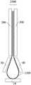
请再次参阅图6和图7,具体而言,第一壳体200与第二壳体300相对折叠至闭合状态时,第一支撑板30、中壳10和第二支撑板40共同形成用于容纳柔性显示屏1100的收容空间。示例性地,第一支撑板30、中壳10和第二支撑板40能够共同形成水滴形的收容空间,此收容空间可用以收容柔性显示屏1100的折弯部1120。Please refer to FIG. 6 and FIG. 7 again. Specifically, when the
第一壳体200与第二壳体300相对展开至打开状态时,第一支撑板30、中壳10和第二支撑板40齐平用以支撑柔性显示屏1100。示例性地,第一支撑板30、中壳10和第二支撑板40能够共同支撑柔性显示屏1100的折弯部1120,使得柔性显示屏1100更为平整,且不易因外力触摸而发生损坏,能够有效提高柔性显示屏1100的可靠性。When the
由此,在本申请的实施例中,折叠装置1000处于闭合状态,即第一壳体200与第二壳体300相对折叠至闭合状态时,第一支撑板30和第二支撑板40能够与中壳10共同形成三段式包裹体,以为柔性显示屏1100的折弯部1120形成近似弧形的强力支撑。一方面,使得柔性显示屏1100的折弯部1120的闭合形态能够较为接近理想闭合形态,故而折叠装置1000能够对闭合形态的柔性显示屏1100提供更为优化的支撑,从而第一壳体200和第二壳体300可以完全闭合,将整机闭合形态存在间隙的可能性降低到最小。另一方面,柔性显示屏1100的折弯部1120能够在保持一定的弯折半径的基础上,使得柔性显示屏1100的折叠最小半径能够满足设计值的需求,柔性显示屏1100的屏幕形态可控,从而能够更好的保护柔性显示屏1100,避免柔性显示屏1100因遇到过折、受拉、受压等问题而造成损伤。Therefore, in the embodiment of the present application, when the
而折叠装置1000处于展开状态,即第一壳体200与第二壳体300相对展开至展平状态时,第一支撑板30和第二支板能够与中壳10共同形成三段式平板结构,以为柔性显示屏1100的折弯部1120形成近似直线形的强力支撑,使得柔性显示屏1100的折弯部1120的展平形态能够具有较好的平面度,故而折叠装置1000能够对展平形态的柔性显示屏1100提供更为优化的支撑。While the
基于上述描述,在本申请的实施例中,折叠装置1000的转动机构100的第一支撑板30、中壳10及第二支撑板40能够在各种形态中共同对柔性显示屏1100提供强力支撑,使得柔性显示屏1100不易在外力作用下发生凹陷,有利于降低显示屏的损坏风险,提高了柔性显示屏1100的可靠性,使得柔性显示屏1100和电子设备2000具有较长的使用寿命。Based on the above description, in the embodiment of the present application, the
以上对本申请实施例进行了详细介绍,本文中应用了具体个例对本申请的原理及实施方式进行了阐述,以上实施例的说明只是用于帮助理解本申请的方法及其核心思想;同时,对于本领域的一般技术人员,依据本申请的思想,在具体实施方式及应用范围上均会有改变之处,综上所述,本说明书内容不应理解为对本申请的限定。The embodiments of the present application have been introduced in detail above, and the principles and implementations of the present application are described in this paper by using specific examples. The descriptions of the above embodiments are only used to help understand the methods and core ideas of the present application; at the same time, for Persons of ordinary skill in the art, based on the idea of the present application, will have changes in the specific implementation manner and application scope. In summary, the contents of this specification should not be construed as a limitation on the present application.
Claims (16)
Priority Applications (28)
| Application Number | Priority Date | Filing Date | Title |
|---|---|---|---|
| CN202011062457.7ACN114338864A (en) | 2020-09-30 | 2020-09-30 | Folding devices and electronic equipment |
| CN202211731544.6ACN116517948A (en) | 2019-12-13 | 2020-12-11 | A kind of rotating shaft mechanism and electronic equipment |
| CN202211739511.6ACN117006149A (en) | 2019-12-13 | 2020-12-11 | Rotating shaft mechanism and electronic equipment |
| PCT/CN2020/135961WO2021115462A1 (en) | 2019-12-13 | 2020-12-11 | Rotary shaft mechanism and electronic device |
| ES20899413TES2985148T3 (en) | 2019-12-13 | 2020-12-11 | Rotary axis mechanism and electronic device |
| EP24161628.3AEP4411511B1 (en) | 2019-12-13 | 2020-12-11 | Rotation shaft structure and electronic device |
| JP2022535886AJP7337276B2 (en) | 2019-12-13 | 2020-12-11 | Rotating shaft structure and electronic device |
| KR1020227023586AKR102798666B1 (en) | 2019-12-13 | 2020-12-11 | Rotating shaft structure and electronic device |
| CN202080033591.6ACN113795683B (en) | 2019-12-13 | 2020-12-11 | Rotating shaft mechanism and electronic equipment |
| EP20899413.7AEP4063674B1 (en) | 2019-12-13 | 2020-12-11 | Rotary shaft mechanism and electronic device |
| KR1020247013824AKR102864988B1 (en) | 2019-12-27 | 2020-12-28 | Electronic device |
| CN202310500162.0ACN116580640A (en) | 2019-12-27 | 2020-12-28 | Electronic equipment |
| CN202211375821.4ACN115766919B (en) | 2019-12-27 | 2020-12-28 | Electronic equipment |
| CN202211380744.1ACN115766920B (en) | 2019-12-27 | 2020-12-28 | Electronic equipment |
| JP2022539094AJP7434569B2 (en) | 2019-12-27 | 2020-12-28 | electronic equipment |
| CN202310498972.7ACN117593954A (en) | 2019-12-27 | 2020-12-28 | Electronic equipment |
| EP20905073.1AEP4072110B1 (en) | 2019-12-27 | 2020-12-28 | Electronic device |
| PCT/CN2020/140445WO2021129882A1 (en) | 2019-12-27 | 2020-12-28 | Electronic device |
| KR1020227025243AKR102661975B1 (en) | 2019-12-27 | 2020-12-28 | electronic device |
| EP24157331.0AEP4395289A3 (en) | 2019-12-27 | 2020-12-28 | Electronic device |
| AU2020412168AAU2020412168B2 (en) | 2019-12-27 | 2020-12-28 | Electronic device |
| CN202310500951.4ACN116564192A (en) | 2019-12-27 | 2020-12-28 | Electronic equipment |
| BR112022012734ABR112022012734A2 (en) | 2019-12-27 | 2020-12-28 | ELECTRONIC DEVICE |
| CN202211376412.6ACN115696808B (en) | 2019-12-27 | 2020-12-28 | Electronic equipment |
| CN202080085591.0ACN115299024B (en) | 2019-12-27 | 2020-12-28 | Electronic equipment |
| US17/487,292US11706886B2 (en) | 2020-09-30 | 2021-09-28 | Folding apparatus and electronic device |
| US17/837,965US12047521B2 (en) | 2019-12-13 | 2022-06-10 | Rotation shaft structure and electronic device |
| US18/747,242US12316791B2 (en) | 2019-12-13 | 2024-06-18 | Rotation shaft structure and electronic device |
Applications Claiming Priority (1)
| Application Number | Priority Date | Filing Date | Title |
|---|---|---|---|
| CN202011062457.7ACN114338864A (en) | 2020-09-30 | 2020-09-30 | Folding devices and electronic equipment |
Publications (1)
| Publication Number | Publication Date |
|---|---|
| CN114338864Atrue CN114338864A (en) | 2022-04-12 |
Family
ID=80821980
Family Applications (1)
| Application Number | Title | Priority Date | Filing Date |
|---|---|---|---|
| CN202011062457.7APendingCN114338864A (en) | 2019-12-13 | 2020-09-30 | Folding devices and electronic equipment |
Country Status (2)
| Country | Link |
|---|---|
| US (1) | US11706886B2 (en) |
| CN (1) | CN114338864A (en) |
Cited By (9)
| Publication number | Priority date | Publication date | Assignee | Title |
|---|---|---|---|---|
| WO2023231368A1 (en)* | 2022-05-31 | 2023-12-07 | Oppo广东移动通信有限公司 | Folding apparatus, foldable housing and electronic device |
| WO2024002280A1 (en)* | 2022-07-01 | 2024-01-04 | 华为技术有限公司 | Rotating shaft assembly and foldable electronic device |
| WO2024040984A1 (en)* | 2022-08-22 | 2024-02-29 | 荣耀终端有限公司 | Rotating shaft apparatus and foldable-screen device |
| WO2024139437A1 (en)* | 2022-12-29 | 2024-07-04 | 华为技术有限公司 | Rotating shaft mechanism and electronic device |
| WO2024139433A1 (en)* | 2022-12-27 | 2024-07-04 | 华为技术有限公司 | Foldable electronic device and rotating shaft mechanism thereof |
| WO2024159757A1 (en)* | 2023-01-31 | 2024-08-08 | 华为技术有限公司 | Rotary shaft mechanism and electronic device |
| WO2024255310A1 (en)* | 2023-06-15 | 2024-12-19 | 华为技术有限公司 | Rotating shaft mechanism and electronic device |
| WO2025113473A1 (en)* | 2023-11-29 | 2025-06-05 | 华为技术有限公司 | Folding mechanism and electronic device |
| WO2025138622A1 (en)* | 2023-12-29 | 2025-07-03 | 华为技术有限公司 | Folding mechanism and electronic device |
Families Citing this family (23)
| Publication number | Priority date | Publication date | Assignee | Title |
|---|---|---|---|---|
| CN112995368B (en)* | 2019-12-13 | 2021-12-21 | 华为技术有限公司 | A hinge and mobile terminal |
| CN114449068A (en)* | 2020-10-31 | 2022-05-06 | 华为技术有限公司 | Hinge mechanism and foldable electronic equipment |
| CN114338864A (en) | 2020-09-30 | 2022-04-12 | 华为技术有限公司 | Folding devices and electronic equipment |
| CN113883156A (en) | 2020-07-01 | 2022-01-04 | 华为技术有限公司 | Folding module and folding electronic equipment |
| KR102798666B1 (en)* | 2019-12-13 | 2025-04-18 | 후아웨이 테크놀러지 컴퍼니 리미티드 | Rotating shaft structure and electronic device |
| CN114205430B (en)* | 2020-09-17 | 2022-11-15 | Oppo广东移动通信有限公司 | Hinge Mechanism and Foldable Electronic Devices |
| CN113067924B (en)* | 2021-03-19 | 2023-05-23 | 维沃移动通信有限公司 | Folding mechanism, support structure and electronic equipment |
| CN115217838A (en)* | 2021-04-16 | 2022-10-21 | 华为技术有限公司 | A folding device and electronic equipment |
| CN113194183B (en)* | 2021-05-21 | 2023-08-22 | 维沃移动通信有限公司 | Folding mechanism and electronic equipment |
| CN115842883B (en)* | 2021-09-18 | 2023-10-24 | 荣耀终端有限公司 | Folding component of electronic equipment and electronic equipment |
| CN217010905U (en)* | 2021-10-19 | 2022-07-19 | 荣耀终端有限公司 | Rotating Mechanisms, Supporting Devices and Electronic Equipment |
| CN116123207A (en)* | 2021-11-12 | 2023-05-16 | 北京小米移动软件有限公司 | Folding hinges and electronics |
| CN116506538A (en)* | 2022-01-18 | 2023-07-28 | 荣耀终端有限公司 | Electronic equipment |
| TWI803201B (en)* | 2022-02-21 | 2023-05-21 | 富世達股份有限公司 | Hinge |
| JP7293436B1 (en)* | 2022-03-11 | 2023-06-19 | レノボ・シンガポール・プライベート・リミテッド | Electronics |
| CN114726938B (en)* | 2022-03-31 | 2023-08-18 | 联想(北京)有限公司 | Rotary connection structure and electronic equipment |
| CN116928202A (en)* | 2022-03-31 | 2023-10-24 | 北京小米移动软件有限公司 | Rotating shaft device and folding electronic equipment |
| CN116940011B (en)* | 2022-03-31 | 2024-06-14 | 荣耀终端有限公司 | Foldable mechanism and foldable terminal |
| CN117119083A (en)* | 2022-05-16 | 2023-11-24 | 华为技术有限公司 | Rotating shaft mechanism and foldable equipment |
| US12306671B2 (en) | 2022-06-03 | 2025-05-20 | Microsoft Technology Licensing, Llc | Timing mechanism for foldable computing device |
| CN115978082B (en)* | 2023-02-08 | 2023-08-11 | 荣耀终端有限公司 | Rotating mechanism, supporting device and electronic equipment |
| US20250130613A1 (en)* | 2023-05-30 | 2025-04-24 | Google Llc | Folding portable display device |
| CN119641783A (en)* | 2023-09-18 | 2025-03-18 | 富世达股份有限公司 | Hinge |
Family Cites Families (100)
| Publication number | Priority date | Publication date | Assignee | Title |
|---|---|---|---|---|
| JP4111957B2 (en) | 2004-04-09 | 2008-07-02 | フェニックス コリア 株式会社 | Portable device including two units that can be rotated and expanded and folded, and hinge device used for the portable device |
| US20070129609A1 (en) | 2004-11-26 | 2007-06-07 | Kazuhiro Kawasaki | Support network system of medical institution |
| JP2010218102A (en) | 2009-03-16 | 2010-09-30 | Sony Corp | Electronic equipment |
| US9176535B2 (en) | 2011-06-03 | 2015-11-03 | Microsoft Technology Licensing, Llc | Flexible display flexure assembly |
| KR101958185B1 (en) | 2011-12-14 | 2019-03-18 | 삼성전자주식회사 | Gear hinge device for portable apparatus |
| US9021657B2 (en) | 2013-02-07 | 2015-05-05 | Samsung Electronics Co., Ltd. | Portable electronic device |
| KR101875855B1 (en) | 2014-02-17 | 2018-07-06 | 삼성전자주식회사 | Hinge apparatus and foldable display apparatus having the same |
| KR101727971B1 (en) | 2014-02-21 | 2017-04-18 | 삼성전자주식회사 | Foldable device |
| KR102309411B1 (en) | 2014-10-27 | 2021-10-06 | 엘지전자 주식회사 | Protable electronic device |
| KR101487189B1 (en) | 2014-11-19 | 2015-01-29 | 주식회사 에스코넥 | Hinge for flexible display device |
| KR102322377B1 (en) | 2014-12-31 | 2021-11-05 | 엘지디스플레이 주식회사 | Foldable display apparatus |
| KR20160089164A (en) | 2015-01-19 | 2016-07-27 | 삼성전자주식회사 | Flexible device and method for controlling shape of display thereof |
| CN104836865B (en) | 2015-04-01 | 2017-05-17 | 京东方科技集团股份有限公司 | Foldable display device |
| US10310551B2 (en)* | 2015-04-09 | 2019-06-04 | Samsung Electronics Co., Ltd. | Foldable device |
| US9983424B2 (en) | 2015-06-08 | 2018-05-29 | Lg Display Co., Ltd. | Foldable display device |
| CN105096752B (en) | 2015-08-25 | 2018-03-06 | 京东方科技集团股份有限公司 | A kind of flexible display panels and display device |
| KR102366516B1 (en) | 2015-08-31 | 2022-02-22 | 엘지디스플레이 주식회사 | Foldable display apparatus |
| CN105491193B (en) | 2015-12-29 | 2018-03-27 | 广东欧珀移动通信有限公司 | Foldable terminal with flexible screen |
| CN205750631U (en) | 2016-01-19 | 2016-11-30 | 杭州安费诺飞凤通信部品有限公司 | Flexible screen supporting hinges, flexible screen device and mobile terminal |
| KR102233720B1 (en) | 2016-03-17 | 2021-03-30 | 코닝 인코포레이티드 | Bendable electronic device modules, articles, and bonding methods to form the same |
| KR102520552B1 (en) | 2016-06-24 | 2023-04-12 | 삼성전자주식회사 | Electronic device including a plurality of display |
| US10705569B2 (en) | 2016-07-08 | 2020-07-07 | Guangdong Oppo Mobile Telecommunications Corp., Ltd. | Support structure for supporting flexible display screen, and flexible display screen module |
| JP6261675B1 (en) | 2016-07-19 | 2018-01-17 | レノボ・シンガポール・プライベート・リミテッド | Portable information equipment |
| KR102630498B1 (en) | 2016-08-12 | 2024-01-31 | 삼성전자주식회사 | Electronic device including flexible display |
| US9677308B1 (en) | 2016-08-18 | 2017-06-13 | Lianhong Art Co., Ltd. | Hinge having movable shaft |
| KR102545778B1 (en)* | 2016-10-11 | 2023-06-21 | (주)에이유플렉스 | Hinge Structure for Folderable Display Device |
| WO2018070778A1 (en) | 2016-10-11 | 2018-04-19 | 박현민 | Hinge structure of foldable display device |
| CN206112430U (en) | 2016-11-01 | 2017-04-19 | 京东方科技集团股份有限公司 | Foldable flexible screen's strutting arrangement and display device |
| CN106601130B (en) | 2016-12-12 | 2019-03-05 | 上海天马微电子有限公司 | Folding flexible display device |
| US10481634B2 (en) | 2017-01-10 | 2019-11-19 | Lenovo (Singapore) Pte. Ltd. | Portable information device |
| CN207010739U (en) | 2017-05-17 | 2018-02-13 | 广东欧珀移动通信有限公司 | Folding mechanism, folding mechanism component and foldable mobile terminal |
| CN207782858U (en) | 2017-06-06 | 2018-08-28 | 杭州安费诺飞凤通信部品有限公司 | Flexible screen mobile terminal hinge and flexible screen mobile terminal |
| TWM551804U (en)* | 2017-06-08 | 2017-11-11 | First Dome Corp | Hinge and foldable electronic device with the hinge |
| CN109257460B (en) | 2017-07-12 | 2024-11-29 | 杭州安费诺飞凤通信部品有限公司 | Hinge of flexible screen mobile terminal and flexible screen mobile terminal |
| CN207115888U (en) | 2017-08-03 | 2018-03-16 | 深圳市柔宇科技有限公司 | Fold mechanism and terminal |
| CN113053250B (en) | 2017-12-28 | 2022-10-04 | 乐金显示有限公司 | Foldable display |
| CN108173995A (en) | 2018-01-08 | 2018-06-15 | 杭州安费诺飞凤通信部品有限公司 | A kind of infolding flexible screen mobile terminal hinge and infolding flexible screen mobile terminal |
| CN110022386B (en) | 2018-01-09 | 2021-01-29 | 华为技术有限公司 | Foldable terminal equipment |
| KR102602282B1 (en) | 2018-02-03 | 2023-11-15 | (주)에이유플렉스 | Elastic Device |
| CN112313729A (en) | 2018-03-12 | 2021-02-02 | 深圳市柔宇科技股份有限公司 | Bending assembly and flexible display device |
| KR102007426B1 (en) | 2018-04-20 | 2019-08-05 | 알티전자 주식회사 | Foldable display device |
| CN112470097A (en) | 2018-05-25 | 2021-03-09 | 深圳市柔宇科技股份有限公司 | Flexible display module and flexible terminal |
| EP3779937B1 (en) | 2018-05-28 | 2025-05-21 | Huawei Technologies Co., Ltd. | Foldable display device |
| TWI673545B (en) | 2018-06-21 | 2019-10-01 | 兆利科技工業股份有限公司 | A Hinge Module For The Foldable Type Device |
| CN108665812B (en) | 2018-06-28 | 2020-12-29 | 上海天马有机发光显示技术有限公司 | A bending device and display device |
| CN108712535A (en) | 2018-06-28 | 2018-10-26 | 努比亚技术有限公司 | Folding mobile terminal |
| CN109032251A (en) | 2018-06-28 | 2018-12-18 | 武汉华星光电半导体显示技术有限公司 | A kind of Flexible Displays mould group and its carrying center |
| CN208421695U (en)* | 2018-07-13 | 2019-01-22 | Oppo广东移动通信有限公司 | Electronic equipment |
| CN208689844U (en) | 2018-07-13 | 2019-04-02 | Oppo广东移动通信有限公司 | Electronic equipment |
| CN208922657U (en) | 2018-08-09 | 2019-05-31 | 深圳市柔宇科技有限公司 | Foldable display device |
| CN208596323U (en) | 2018-08-09 | 2019-03-12 | 深圳市柔宇科技有限公司 | foldable device |
| CN208622359U (en) | 2018-08-27 | 2019-03-19 | 云谷(固安)科技有限公司 | Flexible screen body component and flexible display apparatus |
| CN109118964A (en) | 2018-09-18 | 2019-01-01 | 京东方科技集团股份有限公司 | A kind of flexible display apparatus |
| CN208673636U (en) | 2018-09-19 | 2019-03-29 | 云谷(固安)科技有限公司 | A screen support device and a foldable flexible display device |
| CN108922408B (en) | 2018-09-19 | 2024-02-27 | 云谷(固安)科技有限公司 | Foldable supporting device and foldable flexible display device |
| CN209593488U (en) | 2018-10-26 | 2019-11-05 | Oppo广东移动通信有限公司 | Folding device and electronic equipment |
| CN209375705U (en) | 2018-10-26 | 2019-09-10 | Oppo广东移动通信有限公司 | Rotary shaft mechanism and foldable electronic equipment |
| CN209545628U (en)* | 2018-11-06 | 2019-10-25 | Oppo广东移动通信有限公司 | Electronic equipment |
| CN109658826B (en) | 2018-11-06 | 2022-05-17 | Oppo广东移动通信有限公司 | Flexible screens and electronic devices |
| CN110007715B (en) | 2018-12-10 | 2023-03-31 | 兆利科技工业股份有限公司 | Rotating shaft module of folding device |
| CN209724948U (en) | 2018-12-12 | 2019-12-03 | 杭州安费诺飞凤通信部品有限公司 | The hinge and flexible screen mobile terminal of flexible screen mobile terminal |
| CN209731301U (en) | 2019-01-15 | 2019-12-03 | 杭州安费诺飞凤通信部品有限公司 | A kind of hinge and infolding flexible screen mobile terminal of infolding flexible screen mobile terminal |
| CN209430596U (en) | 2019-01-15 | 2019-09-24 | 龚登明 | A kind of more hinge multi-angle Damping rotation shaft mechanisms |
| US10469635B1 (en) | 2019-01-23 | 2019-11-05 | Motorola Mobility Llc | Hinged electronic device with chambers accommodating a dynamic flexible substrate and corresponding systems |
| CN109830185B (en) | 2019-02-22 | 2024-05-17 | 华为技术有限公司 | Folding component and folding display terminal |
| CN109859630B (en) | 2019-02-22 | 2024-10-11 | 华为技术有限公司 | Folding assembly and folding display terminal |
| CN111615277B (en) | 2019-02-25 | 2021-11-05 | Oppo广东移动通信有限公司 | Rotating device, shell and electronic device |
| CN109686267A (en) | 2019-02-26 | 2019-04-26 | 武汉华星光电半导体显示技术有限公司 | OLED display |
| CN209358590U (en) | 2019-02-28 | 2019-09-06 | Oppo广东移动通信有限公司 | Foldable mobile terminal |
| CN110061039B (en) | 2019-04-26 | 2021-03-02 | 京东方科技集团股份有限公司 | Flexible display panel and display device |
| CN109979328B (en) | 2019-04-26 | 2024-12-20 | 成都拓米电子装备制造有限公司 | An inward folding hinge mechanism with good supporting effect |
| CN110010008B (en) | 2019-04-26 | 2024-12-20 | 成都拓米电子装备制造有限公司 | An inward folding hinge mechanism suitable for display device |
| KR102375556B1 (en) | 2019-04-30 | 2022-03-17 | 삼성전자주식회사 | Structure of Hinge and electronic device including the same |
| CN110166591B (en) | 2019-05-07 | 2025-04-04 | 珠海格力电器股份有限公司 | Folding device, flexible display and mobile terminal |
| CN110058444B (en) | 2019-05-08 | 2022-04-12 | 武汉天马微电子有限公司 | Display module and display device |
| CN110265438B (en) | 2019-06-06 | 2021-06-01 | 武汉华星光电半导体显示技术有限公司 | Flexible display panel and display device |
| CN210799707U (en) | 2019-06-14 | 2020-06-19 | 深圳市长盈精密技术股份有限公司 | Hinge mechanism, folding display device and communication equipment |
| CN110189638B (en) | 2019-06-28 | 2022-01-28 | 武汉天马微电子有限公司 | Display module and display device |
| CN110445913B (en) | 2019-07-31 | 2024-07-30 | 华为技术有限公司 | Folding components and electronic devices |
| CN110557481B (en) | 2019-08-28 | 2021-06-15 | 华为技术有限公司 | Electronic equipment |
| CN110552953A (en) | 2019-09-04 | 2019-12-10 | 东莞市劲丰电子有限公司 | Lever type inward-folding synchronous rotating mechanism |
| CN110580854B (en) | 2019-09-12 | 2021-11-09 | 云谷(固安)科技有限公司 | Flexible screen supporting structure and folding screen |
| CN110853510B (en) | 2019-10-23 | 2020-12-25 | 武汉华星光电半导体显示技术有限公司 | Foldable supporting structure and display device |
| CN110671423B (en) | 2019-11-06 | 2024-05-17 | 东莞市环力智能科技有限公司 | Three-section folding hinge for flexible screen and mobile device thereof |
| CN113915227A (en) | 2020-07-08 | 2022-01-11 | 华为技术有限公司 | Spindle mechanism and electronic equipment |
| CN114338864A (en) | 2020-09-30 | 2022-04-12 | 华为技术有限公司 | Folding devices and electronic equipment |
| KR102798666B1 (en) | 2019-12-13 | 2025-04-18 | 후아웨이 테크놀러지 컴퍼니 리미티드 | Rotating shaft structure and electronic device |
| CN112995368B (en) | 2019-12-13 | 2021-12-21 | 华为技术有限公司 | A hinge and mobile terminal |
| CN114449068A (en) | 2020-10-31 | 2022-05-06 | 华为技术有限公司 | Hinge mechanism and foldable electronic equipment |
| CN110992833B (en) | 2019-12-19 | 2020-10-23 | 倪承明 | Rotating shaft type folding assembly for flexible screen mobile terminal |
| CN110985524B (en) | 2019-12-20 | 2024-09-06 | 深圳市长盈精密技术股份有限公司 | Damping mechanism, folding display device and communication equipment |
| CN115988114B (en) | 2019-12-27 | 2024-11-15 | 华为技术有限公司 | Flexible screen and foldable equipment |
| CN113280033B (en) | 2020-02-20 | 2022-07-29 | 北京小米移动软件有限公司 | Hinge, hinge assembly and folding electronic device |
| KR102152040B1 (en) | 2020-04-07 | 2020-09-04 | 주식회사 하이맥 | Folding hinge module for mobile terminal |
| CN111327739B (en) | 2020-04-09 | 2025-02-25 | 东莞市环力智能科技有限公司 | U-shaped hinge and mobile terminal |
| CN116336072A (en) | 2020-05-27 | 2023-06-27 | 三星电子株式会社 | Arm structure, hinge structure including arm structure, and electronic device including hinge structure |
| CN111653202B (en) | 2020-06-30 | 2022-03-11 | 武汉天马微电子有限公司 | Foldable display device and use method thereof |
| CN111677747A (en) | 2020-07-08 | 2020-09-18 | 拓米(成都)应用技术研究院有限公司 | Hinge mechanism with length compensation function and folding display device |
| JP7364774B2 (en) | 2021-01-05 | 2023-10-18 | サムスン エレクトロニクス カンパニー リミテッド | Electronic devices containing hinge structures |
| CN115370655B (en) | 2021-05-18 | 2024-06-25 | 北京小米移动软件有限公司 | Rotating modules and electronic devices |
- 2020
- 2020-09-30CNCN202011062457.7Apatent/CN114338864A/enactivePending
- 2021
- 2021-09-28USUS17/487,292patent/US11706886B2/enactiveActive
Cited By (9)
| Publication number | Priority date | Publication date | Assignee | Title |
|---|---|---|---|---|
| WO2023231368A1 (en)* | 2022-05-31 | 2023-12-07 | Oppo广东移动通信有限公司 | Folding apparatus, foldable housing and electronic device |
| WO2024002280A1 (en)* | 2022-07-01 | 2024-01-04 | 华为技术有限公司 | Rotating shaft assembly and foldable electronic device |
| WO2024040984A1 (en)* | 2022-08-22 | 2024-02-29 | 荣耀终端有限公司 | Rotating shaft apparatus and foldable-screen device |
| WO2024139433A1 (en)* | 2022-12-27 | 2024-07-04 | 华为技术有限公司 | Foldable electronic device and rotating shaft mechanism thereof |
| WO2024139437A1 (en)* | 2022-12-29 | 2024-07-04 | 华为技术有限公司 | Rotating shaft mechanism and electronic device |
| WO2024159757A1 (en)* | 2023-01-31 | 2024-08-08 | 华为技术有限公司 | Rotary shaft mechanism and electronic device |
| WO2024255310A1 (en)* | 2023-06-15 | 2024-12-19 | 华为技术有限公司 | Rotating shaft mechanism and electronic device |
| WO2025113473A1 (en)* | 2023-11-29 | 2025-06-05 | 华为技术有限公司 | Folding mechanism and electronic device |
| WO2025138622A1 (en)* | 2023-12-29 | 2025-07-03 | 华为技术有限公司 | Folding mechanism and electronic device |
Also Published As
| Publication number | Publication date |
|---|---|
| US20220104370A1 (en) | 2022-03-31 |
| US11706886B2 (en) | 2023-07-18 |
Similar Documents
| Publication | Publication Date | Title |
|---|---|---|
| CN114338864A (en) | Folding devices and electronic equipment | |
| KR102813864B1 (en) | Foldable devices and electronic devices | |
| WO2021007912A1 (en) | Bendable device | |
| CN113542457A (en) | Folding devices and electronic equipment | |
| WO2023274233A1 (en) | Rotation shaft mechanism and electronic device | |
| US20250071196A1 (en) | Hinge Mechanism and Foldable Device | |
| CN116434658A (en) | foldable display device | |
| CN114338865A (en) | A folding device and foldable electronic device | |
| CN115002247A (en) | Main swing arm, rotating shaft mechanism and foldable mobile terminal | |
| CN117128233B (en) | Damping mechanism, folding hinge and electronic equipment | |
| CN116696929A (en) | A damping mechanism, folding hinge and electronic equipment | |
| WO2023051210A1 (en) | Rotating shaft mechanism and foldable mobile terminal | |
| CN117145856A (en) | Rotating shaft mechanisms and foldable electronic devices | |
| CN116696928B (en) | Damping mechanism, folding hinge and electronic equipment | |
| WO2024087992A1 (en) | Rotating shaft mechanism and foldable electronic device | |
| US20250155935A1 (en) | Rotary Mechanism and Electronic Device | |
| US20240396986A1 (en) | Folding apparatus and electronic device | |
| CN116838702B (en) | Rotating mechanism and foldable electronic device | |
| CN118110726B (en) | Rotating shaft mechanism and electronic equipment | |
| CN116838699B (en) | Rotating mechanism and foldable electronic device | |
| CN118008940A (en) | Rotating shaft assembly and foldable electronic equipment | |
| CN119855997A (en) | Rotating mechanism and foldable electronic device | |
| CN120226338A (en) | Folding assembly and electronic equipment | |
| WO2025060468A1 (en) | Rotating shaft mechanism and foldable electronic device | |
| WO2025020532A1 (en) | Rotating shaft mechanism and electronic device |
Legal Events
| Date | Code | Title | Description |
|---|---|---|---|
| PB01 | Publication | ||
| PB01 | Publication | ||
| SE01 | Entry into force of request for substantive examination | ||
| SE01 | Entry into force of request for substantive examination |