CN114326128A - Focus Adjustment for Multi-Plane Head Mounted Displays - Google Patents
Focus Adjustment for Multi-Plane Head Mounted DisplaysDownload PDFInfo
- Publication number
- CN114326128A CN114326128ACN202210141252.0ACN202210141252ACN114326128ACN 114326128 ACN114326128 ACN 114326128ACN 202210141252 ACN202210141252 ACN 202210141252ACN 114326128 ACN114326128 ACN 114326128A
- Authority
- CN
- China
- Prior art keywords
- virtual
- user
- depth
- scene
- optical
- Prior art date
- Legal status (The legal status is an assumption and is not a legal conclusion. Google has not performed a legal analysis and makes no representation as to the accuracy of the status listed.)
- Granted
Links
Images


Classifications
- G—PHYSICS
- G02—OPTICS
- G02B—OPTICAL ELEMENTS, SYSTEMS OR APPARATUS
- G02B27/00—Optical systems or apparatus not provided for by any of the groups G02B1/00 - G02B26/00, G02B30/00
- G02B27/01—Head-up displays
- G02B27/017—Head mounted
- G02B27/0172—Head mounted characterised by optical features
- G—PHYSICS
- G06—COMPUTING OR CALCULATING; COUNTING
- G06F—ELECTRIC DIGITAL DATA PROCESSING
- G06F3/00—Input arrangements for transferring data to be processed into a form capable of being handled by the computer; Output arrangements for transferring data from processing unit to output unit, e.g. interface arrangements
- G06F3/01—Input arrangements or combined input and output arrangements for interaction between user and computer
- G06F3/011—Arrangements for interaction with the human body, e.g. for user immersion in virtual reality
- G06F3/013—Eye tracking input arrangements
- G—PHYSICS
- G02—OPTICS
- G02B—OPTICAL ELEMENTS, SYSTEMS OR APPARATUS
- G02B27/00—Optical systems or apparatus not provided for by any of the groups G02B1/00 - G02B26/00, G02B30/00
- G02B27/01—Head-up displays
- G02B27/0101—Head-up displays characterised by optical features
- G02B2027/0138—Head-up displays characterised by optical features comprising image capture systems, e.g. camera
- G—PHYSICS
- G02—OPTICS
- G02B—OPTICAL ELEMENTS, SYSTEMS OR APPARATUS
- G02B27/00—Optical systems or apparatus not provided for by any of the groups G02B1/00 - G02B26/00, G02B30/00
- G02B27/01—Head-up displays
- G02B27/0101—Head-up displays characterised by optical features
- G02B2027/014—Head-up displays characterised by optical features comprising information/image processing systems
- G—PHYSICS
- G02—OPTICS
- G02B—OPTICAL ELEMENTS, SYSTEMS OR APPARATUS
- G02B27/00—Optical systems or apparatus not provided for by any of the groups G02B1/00 - G02B26/00, G02B30/00
- G02B27/01—Head-up displays
- G02B27/0179—Display position adjusting means not related to the information to be displayed
- G02B2027/0185—Displaying image at variable distance
- G—PHYSICS
- G02—OPTICS
- G02B—OPTICAL ELEMENTS, SYSTEMS OR APPARATUS
- G02B27/00—Optical systems or apparatus not provided for by any of the groups G02B1/00 - G02B26/00, G02B30/00
- G02B27/01—Head-up displays
- G02B27/0179—Display position adjusting means not related to the information to be displayed
- G02B2027/0187—Display position adjusting means not related to the information to be displayed slaved to motion of at least a part of the body of the user, e.g. head, eye
- G—PHYSICS
- G02—OPTICS
- G02B—OPTICAL ELEMENTS, SYSTEMS OR APPARATUS
- G02B7/00—Mountings, adjusting means, or light-tight connections, for optical elements
- G02B7/02—Mountings, adjusting means, or light-tight connections, for optical elements for lenses
- G02B7/04—Mountings, adjusting means, or light-tight connections, for optical elements for lenses with mechanism for focusing or varying magnification
Landscapes
- Engineering & Computer Science (AREA)
- Physics & Mathematics (AREA)
- General Engineering & Computer Science (AREA)
- Theoretical Computer Science (AREA)
- General Physics & Mathematics (AREA)
- Human Computer Interaction (AREA)
- Optics & Photonics (AREA)
Abstract
Translated fromChinese
Description
Translated fromChinese本申请是申请日为2018年2月20日,申请号为201880013205.X,发明名称为“聚焦调整多平面头戴式显示器”的申请的分案申请。This application is a divisional application of an application with an application date of February 20, 2018, an application number of 201880013205.X, and an invention title of "focus adjustment multi-plane head-mounted display".
背景background
本公开大体上涉及增强来自电子显示器的图像,并且具体地涉及具有位于不同光学距离处的两个或更多个显示平面的多平面显示器,显示平面可以基于在由头戴式显示器呈现的场景内的位置被动态地调整。The present disclosure relates generally to enhancing images from electronic displays, and in particular to multi-planar displays having two or more display planes located at different optical distances, the display planes may be based on within a scene presented by a head mounted display The position is dynamically adjusted.
头戴式显示器可用于模拟人工或虚拟环境。例如,立体图像可以显示在耳机(headset)内部的电子显示器上以模拟深度的错觉(illusion of depth),并且头部跟踪传感器可以用于估计用户正在观看人工环境的哪个部分。然而,这种模拟可能导致由现有耳机不能正确地提供或以其他方式补偿辐辏(vergence)和调节冲突引起的视觉疲劳和恶心。Head-mounted displays can be used to simulate artificial or virtual environments. For example, stereoscopic images can be displayed on an electronic display inside a headset to simulate the illusion of depth, and head tracking sensors can be used to estimate which part of the artificial environment the user is viewing. However, such simulations may result in visual fatigue and nausea caused by existing headsets that do not properly provide or otherwise compensate for vergence and accommodation conflicts.
概述Overview
多平面头戴式显示器(HMD)对于每只眼睛包括位于光学距离处的两个或更多个虚拟显示平面,其可以基于用户观看的由HMD所呈现的场景内的位置被动态地调整。例如,场景呈现在HMD的两个或更多个电子显示元件(例如,屏幕)上。使用变焦系统(例如,机械地改变在光学块(optics block)中的透镜系统和电子显示元件之间的距离的元件、改变光学块中的透镜系统中的一个或更多个透镜的形状的元件,等等)基于在用户正在看的场景中的位置或对象来调整将来自电子显示元件的图像光引导到用户的眼睛的光学块的焦距。A multi-plane head mounted display (HMD) includes two or more virtual display planes at optical distances for each eye, which can be dynamically adjusted based on the user's viewing position within the scene presented by the HMD. For example, a scene is presented on two or more electronic display elements (eg, screens) of the HMD. Use a zoom system (eg, an element that mechanically changes the distance between a lens system in an optics block and an electronic display element, an element that changes the shape of one or more lenses in a lens system in an optics block) , etc.) adjust the focal length of the optical block that directs the image light from the electronic display element to the user's eye based on the position or object in the scene the user is looking at.
在一个实施例中,头戴式显示器(HMD)(对于用户的每只眼睛)包括位于距HMD的光学块第一光学距离处的第一电子显示器和位于距光学块第二光学距离处的第二电子显示器。每个电子显示器被配置为向戴着HMD的用户显示虚拟场景的不同虚拟平面。在一个实施例中,在虚拟场景中的对象被映射到由内容创建者提供的场景几何结构或深度信息,并且每个电子显示器基于它们的场景几何结构来被映射到对象的不同子集。例如,显示位于第一光学距离处的第一虚拟显示平面的第一电子显示器显示在虚拟场景内的被映射到在第一光学距离处的第一虚拟显示平面处或附近的场景几何结构的对象。因此,每个随后的电子显示器基于虚拟显示平面的位置和场景几何结构来显示不同的对象。因此,来自每个虚拟显示平面的虚拟场景内容被组合用于由观看用户观看。因此,电子显示器中的至少一个至少是半透明的,以允许虚拟场景的图像光被组合以用于由戴着HMD的用户观看。In one embodiment, a head mounted display (HMD) (for each eye of the user) includes a first electronic display located at a first optical distance from an optical block of the HMD and a first electronic display located at a second optical distance from the optical block Two electronic displays. Each electronic display is configured to display a different virtual plane of the virtual scene to the user wearing the HMD. In one embodiment, objects in the virtual scene are mapped to scene geometry or depth information provided by the content creator, and each electronic display is mapped to a different subset of objects based on their scene geometry. For example, a first electronic display displaying a first virtual display plane at a first optical distance displays objects within the virtual scene that are mapped to scene geometry at or near the first virtual display plane at the first optical distance . Thus, each subsequent electronic display displays a different object based on the position of the virtual display plane and scene geometry. Thus, the virtual scene content from each virtual display plane is combined for viewing by the viewing user. Accordingly, at least one of the electronic displays is at least translucent to allow image light of the virtual scene to be combined for viewing by a user wearing the HMD.
在可选的实施例中,头戴式显示器(HMD)(对于用户的每只眼睛)包括顺序地显示每个虚拟显示平面的单个电子显示器。如上所述,虚拟场景中的对象被映射到虚拟场景的场景几何结构,并且两个或更多个虚拟平面中的每一个基于场景几何结构显示对象的不同子集,但是如前所述是顺序地而不是同时地显示。In an alternative embodiment, the head mounted display (HMD) (for each eye of the user) includes a single electronic display that sequentially displays each virtual display plane. As described above, objects in the virtual scene are mapped to the scene geometry of the virtual scene, and each of the two or more virtual planes displays a different subset of objects based on the scene geometry, but sequentially as described above displayed instead of simultaneously.
此外,HMD基于在用户观看的由虚拟现实耳机呈现的虚拟场景内的位置来自动调整它的焦点。虚拟场景呈现在一个或更多个电子显示器上,以及使用变焦元件(例如,机械地改变在光学块中的透镜系统和电子显示元件之间的距离的元件、改变光学块中的透镜系统中的一个或更多个透镜的形状的元件等)基于用户正在看的虚拟场景中的位置或对象来调整将来自电子显示器的图像光引导到用户的眼睛的光学块的焦距。例如,HMD跟踪用户的眼睛以近似凝视线,并将包括辐辏深度的凝视点确定为凝视线的所估计的交叉点。凝视点识别由HMD呈现给用户的虚拟场景的特定帧的对象或焦平面。Furthermore, the HMD automatically adjusts its focus based on the position within the virtual scene presented by the virtual reality headset as viewed by the user. The virtual scene is presented on one or more electronic displays and using zoom elements (eg, elements that mechanically change the distance between the lens system in the optical block and the electronic display element, changing the One or more lens-shaped elements, etc.) to adjust the focal length of the optical blocks that direct image light from the electronic display to the user's eyes based on the position or object in the virtual scene the user is looking at. For example, the HMD tracks the user's eyes to approximate the gaze line and determines the gaze point including the vergence depth as the estimated intersection of the gaze line. The gaze point identifies the object or focal plane of a particular frame of the virtual scene presented to the user by the HMD.
根据本发明的实施例特别是在针对HMD和耳机的所附权利要求中被公开,其中在一个权利要求类别例如HMD中提到的任何特征也可以在另一个权利要求类别例如耳机、系统、方法、存储介质或计算机程序产品中被要求保护。在所附权利要求中的从属性或反向引用仅为了形式原因而被选择。然而,也可以要求保护从对任何先前权利要求的审慎的反向引用(特别是多项从属)产生的任何主题,使得权利要求及其特征的任何组合被公开并可被要求保护,而不考虑在所附权利要求中选择的从属性。可以被要求保护的主题不仅包括如在所附权利要求中阐述的特征的组合,而且还包括在权利要求中的特征的任何其他组合,其中在权利要求中提到的每个特征可以与在权利要求中的任何其他特征或其他特征的组合相结合。此外,在本文描述或描绘的实施例和特征中的任一个可以在单独的权利要求中和/或在与本文描述或描绘的任何实施例和特征或与所附权利要求的任何特征的任何组合中被要求保护。Embodiments according to the invention are disclosed in particular in the appended claims directed to HMDs and headsets, wherein any feature mentioned in one claim category such as HMD may also be included in another claim category such as headset, system, method , storage medium or computer program product is claimed. Dependencies or back-references in the appended claims have been selected for formal reasons only. However, any subject matter that arises from careful back-reference (in particular multiple dependencies) to any preceding claim may also be claimed, such that any combination of claims and their features is disclosed and can be claimed, irrespective of Selected Dependencies in the Attached Claims. The claimed subject matter includes not only the combination of features as set out in the appended claims, but also any other combination of features in the claims, wherein each feature mentioned in the claims may be combined with the any other feature or combination of other features in the requirements. Furthermore, any of the embodiments and features described or depicted herein may be in separate claims and/or in any combination with any embodiments and features described or depicted herein or with any features in the appended claims claimed protection.
在根据本发明的实施例中,头戴式显示器(HMD)可以包括:In an embodiment according to the present invention, a head mounted display (HMD) may include:
至少一个处理器;at least one processor;
第一电子显示器,其被配置为向戴着HMD的用户显示在虚拟场景内的第一虚拟平面;a first electronic display configured to display a first virtual plane within the virtual scene to a user wearing the HMD;
第二电子显示器,其被配置为向戴着HMD的用户显示虚拟场景的第二虚拟平面,第一虚拟平面相对于第二虚拟平面位于不同的光学深度处;a second electronic display configured to display a second virtual plane of the virtual scene to a user wearing the HMD, the first virtual plane being located at a different optical depth relative to the second virtual plane;
光学块,其被配置为将来自第一电子显示器和第二电子显示器的光引导到HMD的出射光瞳;an optical block configured to direct light from the first electronic display and the second electronic display to an exit pupil of the HMD;
包括图像捕获元件的眼动跟踪系统,该眼动跟踪系统被配置为确定用户的每只眼睛的眼睛位置和用户的每只眼睛的凝视线;an eye-tracking system including an image capture element, the eye-tracking system being configured to determine the eye position of each eye of the user and the gaze line of each eye of the user;
包括指令的存储器,该指令当被至少一个处理器执行时使至少一个处理器:memory comprising instructions that, when executed by at least one processor, cause at least one processor to:
基于用户的每只眼睛的凝视线的所估计的交叉点来确定用户的辐辏深度;以及determining the user's vergence depth based on the estimated intersection of the gaze lines of each eye of the user; and
变焦致动块,其被配置为至少部分地基于辐辏深度来改变光学块的焦距。A zoom actuation block configured to change a focal length of the optical block based at least in part on the vergence depth.
在根据本发明的实施例中,HMD可以包括:一个或更多个光学组合元件,其中第一电子显示器垂直于第二电子显示器定位,并且一个或更多个光学组合元件将虚拟场景的第一虚拟平面与虚拟场景的第二虚拟平面组合以用于由戴着HMD的用户观看。In an embodiment according to the invention, the HMD may include: one or more optical combination elements, wherein the first electronic display is positioned perpendicular to the second electronic display, and the one or more optical combination elements combine the first electronic display of the virtual scene The virtual plane is combined with a second virtual plane of the virtual scene for viewing by a user wearing the HMD.
虚拟场景中的对象可以被映射到由内容创建者提供的场景几何结构或深度信息,第一电子显示器可以被映射到第一组场景几何结构,以及第二电子显示器可以被映射到不同的第二组场景几何结构。Objects in the virtual scene may be mapped to scene geometry or depth information provided by the content creator, the first electronic display may be mapped to a first set of scene geometry, and the second electronic display may be mapped to a different second Group scene geometry.
第一电子显示器和第二电子显示器中的至少一个可以是至少半透明的以允许虚拟场景的图像光被组合用于由戴着HMD的用户观看。At least one of the first electronic display and the second electronic display may be at least translucent to allow image light of the virtual scene to be combined for viewing by a user wearing the HMD.
变焦致动块可以被配置成通过改变在光学块与第一电子显示器和第二电子显示器之间的距离来改变光学块的焦距。The zoom actuation block may be configured to change the focal length of the optical block by changing the distance between the optical block and the first and second electronic displays.
变焦致动块可以被配置成通过改变在光学块中包括的透镜的形状或光路长度来改变光学块的焦距。The zoom actuation block may be configured to change the focal length of the optical block by changing the shape or optical path length of a lens included in the optical block.
改变光学块的透镜的形状或光路长度可以包括使用从由下列项组成的组中选择的至少一个:形状改变聚合物透镜、液体透镜和电润湿、Alvarez-Lohmann透镜、可变形膜反射镜、液晶(电活性)透镜、纯相位空间光调制器(SLM)及这些项的任何组合。Changing the shape or optical path length of the lenses of the optical block may include using at least one selected from the group consisting of: shape changing polymer lenses, liquid lenses and electrowetting, Alvarez-Lohmann lenses, deformable film mirrors, Liquid crystal (electroactive) lenses, pure phase spatial light modulators (SLMs), and any combination of these.
在根据本发明的实施例中,HMD可以包括:In an embodiment according to the present invention, the HMD may include:
至少一个处理器;at least one processor;
电子显示器,其被配置为顺序地显示虚拟场景的两个或更多个虚拟平面,其中在虚拟场景中的对象被映射到虚拟场景的场景几何结构,并且两个或更多个虚拟平面中的每一个基于场景几何结构来显示对象的不同子集;An electronic display configured to sequentially display two or more virtual planes of a virtual scene, wherein objects in the virtual scene are mapped to the scene geometry of the virtual scene, and wherein objects in the two or more virtual planes are mapped Each displays a different subset of objects based on scene geometry;
光学块,其被配置为将来自电子显示器的光引导到HMD的出射光瞳;an optical block configured to direct light from the electronic display to the exit pupil of the HMD;
眼动跟踪系统,其被配置为确定:An eye-tracking system that is configured to determine:
用户的每只眼睛的眼睛位置,the eye position of each eye of the user,
基于每只眼睛的眼睛位置的每只眼睛的凝视线,以及The gaze line of each eye based on the eye position of each eye, and
对应于凝视线的交叉点的辐辏深度;以及the vergence depth corresponding to the intersection of the gaze lines; and
变焦致动块,其被配置为至少部分地基于对应于用户在虚拟场景内的观看位置的用户的每只眼睛的辐辏深度来改变光学块的焦距。A zoom actuation block configured to change a focal length of the optical block based, at least in part, on a vergence depth of each eye of the user corresponding to a viewing position of the user within the virtual scene.
变焦致动块可以被配置成以固定聚焦模式振荡,并且在顺序地显示两个或更多个虚拟平面之间的电子显示器刷新可以被定时以基于场景几何结构中的至少一个来创建在光学深度处的两个或更多个虚拟显示平面。The zoom actuation block may be configured to oscillate in a fixed focus mode, and electronic display refreshes between sequentially displaying two or more virtual planes may be timed to create an optical depth based on at least one of the scene geometry two or more virtual display planes at .
可以基于用户在虚拟场景中的观看位置在观看者的辐辏深度处呈现两个或更多个虚拟显示平面中的一个。One of the two or more virtual display planes may be presented at the viewer's vergence depth based on the user's viewing position in the virtual scene.
变焦致动块可以被配置成通过改变在光学块和电子显示器之间的距离来改变光学块的焦距。The zoom actuation block may be configured to change the focal length of the optical block by changing the distance between the optical block and the electronic display.
变焦致动块可以被配置成通过改变在光学块中包括的透镜的形状或光路长度来改变光学块的焦距。The zoom actuation block may be configured to change the focal length of the optical block by changing the shape or optical path length of a lens included in the optical block.
改变光学块的透镜的形状或光路长度可以包括使用从由下列项组成的组中选择的至少一个:形状改变聚合物透镜、液体透镜和电润湿、Alvarez-Lohmann透镜、可变形膜反射镜、液晶(电活性)透镜、纯相位空间光调制器(SLM)及其任何组合。Changing the shape or optical path length of the lenses of the optical block may include using at least one selected from the group consisting of: shape changing polymer lenses, liquid lenses and electrowetting, Alvarez-Lohmann lenses, deformable film mirrors, Liquid crystal (electroactive) lenses, pure phase spatial light modulators (SLMs), and any combination thereof.
在根据本发明的实施例中,耳机可以包括:In an embodiment according to the present invention, the earphone may comprise:
至少一个处理器;at least one processor;
第一电子显示器,其被配置为向戴着耳机的用户显示在虚拟场景内的第一虚拟平面;a first electronic display configured to display a first virtual plane within the virtual scene to a user wearing the headset;
第二电子显示器,其被配置为向戴着耳机的用户显示虚拟场景的第二虚拟平面,第一虚拟平面相对于第二虚拟平面位于不同的光学深度处;a second electronic display configured to display a second virtual plane of the virtual scene to a user wearing the headset, the first virtual plane being located at a different optical depth relative to the second virtual plane;
光学块,其被配置为将来自第一电子显示器和第二电子显示器的光引导到耳机的出射光瞳;an optical block configured to direct light from the first electronic display and the second electronic display to an exit pupil of the headset;
包括图像捕获元件的眼动跟踪系统,该眼动跟踪系统被配置为确定用户的每只眼睛的眼睛位置、基于眼睛位置的用户的每只眼睛的凝视线以及对应于用户在虚拟场景内的观看位置的辐辏深度;以及An eye tracking system including an image capture element configured to determine the eye position of each eye of a user, a gaze line of each eye of the user based on the eye position, and corresponding to the user's viewing within a virtual scene the vergence depth of the location; and
变焦致动块,其被配置为至少部分地基于辐辏深度来改变光学块的焦距。A zoom actuation block configured to change a focal length of the optical block based at least in part on the vergence depth.
第一电子显示器可以垂直于第二电子显示器定位,以及一个或更多个光学组合元件可以将虚拟场景的第一虚拟平面与虚拟场景的第二虚拟平面组合以用于由戴着耳机的用户观看。The first electronic display may be positioned perpendicular to the second electronic display, and the one or more optical combining elements may combine the first virtual plane of the virtual scene with the second virtual plane of the virtual scene for viewing by a user wearing the headset .
在虚拟场景中的对象可以被映射到由内容创建者提供的场景几何结构或深度信息,第一电子显示器可以被映射到第一组场景几何结构,以及第二电子显示器可以被映射到不同的第二组场景几何结构。Objects in the virtual scene may be mapped to scene geometry or depth information provided by the content creator, the first electronic display may be mapped to a first set of scene geometry, and the second electronic display may be mapped to a different Two sets of scene geometries.
第一电子显示器和第二电子显示器中的至少一个可以是至少半透明的以允许虚拟场景的图像光被组合用于由戴着耳机的用户观看。At least one of the first electronic display and the second electronic display may be at least translucent to allow image light of the virtual scene to be combined for viewing by a user wearing the headset.
变焦致动块可以被配置成通过改变在光学块与第一电子显示器和第二电子显示器之间的距离来改变光学块的焦距。The zoom actuation block may be configured to change the focal length of the optical block by changing the distance between the optical block and the first and second electronic displays.
变焦致动块可以被配置成通过改变在光学块中包括的透镜的形状或光路长度来改变光学块的焦距。The zoom actuation block may be configured to change the focal length of the optical block by changing the shape or optical path length of a lens included in the optical block.
改变光学块的透镜的形状或光路长度可以包括使用从由下列项组成的组中选择的至少一个:形状改变聚合物透镜、液体透镜和电润湿、Alvarez-Lohmann透镜、可变形膜反射镜、液晶(电活性)透镜、纯相位空间光调制器(SLM)及这些项的任何组合。Changing the shape or optical path length of the lenses of the optical block may include using at least one selected from the group consisting of: shape changing polymer lenses, liquid lenses and electrowetting, Alvarez-Lohmann lenses, deformable film mirrors, Liquid crystal (electroactive) lenses, pure phase spatial light modulators (SLMs), and any combination of these.
附图简述Brief Description of Drawings
图1示出了根据一个实施例的示例多平面显示器,其中焦平面的位置可以由变焦系统调节。FIG. 1 illustrates an example multi-planar display in which the position of the focal plane can be adjusted by a zoom system, according to one embodiment.
图2示出了根据一个实施例的示例平面顺序变焦多平面显示器。FIG. 2 illustrates an example plane sequential zoom multi-plane display according to one embodiment.
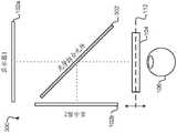
图3示出了根据一个实施例的示例平面同步变焦多平面显示器,其包括分束器以引导来自两个垂直相对的电子显示器的光。Figure 3 illustrates an example planar synchronized zoom multi-planar display that includes a beam splitter to direct light from two vertically opposed electronic displays, according to one embodiment.
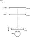
图4示出了根据一个实施例的具有光学串联的两个电子显示器的示例平面同步变焦多平面显示器。4 illustrates an example planar simultaneous zoom multi-planar display with two electronic displays optically connected in series, according to one embodiment.
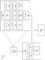
图5示出了根据一个实施例的示例变焦系统。FIG. 5 illustrates an example zoom system according to one embodiment.
图6示出了根据一个实施例的包括用于跟踪眼睛位置的照相机的多平面头戴式显示器的横截面。6 illustrates a cross-section of a multi-planar head mounted display including a camera for tracking eye position, according to one embodiment.
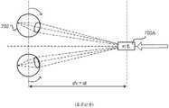
图7A示出了在真实世界中的辐辏和眼睛焦距之间的关系。Figure 7A shows the relationship between vergence and eye focal length in the real world.
图7B示出了在三维显示器中辐辏和眼睛焦距之间的冲突。Figure 7B shows the conflict between vergence and eye focal length in a three-dimensional display.
图8A示出了根据一个实施例的相对于电子显示器在第一位置上的多平面头戴式显示器的光学块。8A illustrates the optical block of a multi-planar head mounted display in a first position relative to an electronic display, according to one embodiment.
图8B示出了根据一个实施例的使用变焦元件来移动的相对于图8A在第二位置上的光学块。8B illustrates the optical block in a second position relative to FIG. 8A for movement using a zoom element, according to one embodiment.
附图仅为了说明的目的描绘了本公开的实施例。本领域中的技术人员从下面的描述中将容易认识到,本文所说明的结构和方法的可选实施例可以被采用而不偏离本文描述的本公开的原理或所提及的益处。The drawings depict embodiments of the present disclosure for purposes of illustration only. Those skilled in the art will readily appreciate from the following description that alternative embodiments of the structures and methods described herein may be employed without departing from the principles of the disclosure described herein or the benefits mentioned.
详细描述Detailed Description
综述Overview
多平面头戴式显示器(HMD)对于每只眼睛包括位于光学距离处的两个或更多个人工显示平面,其可以基于用户观看的由HMD所呈现的场景内的位置来被动态地调整。例如,场景呈现在HMD的两个或更多个电子显示元件(例如,屏幕)上。使用变焦系统(例如,机械地改变在光学块中的透镜系统和电子显示元件之间的距离的元件、改变光学块中的透镜系统中的一个或更多个透镜的形状的元件等)基于在用户正在看的场景中的位置或对象来调整将来自电子显示元件的图像光引导到用户的眼睛的光学块的焦距。A multi-plane head mounted display (HMD) includes two or more artificial display planes located at optical distances for each eye, which can be dynamically adjusted based on the position within the scene presented by the HMD viewed by the user. For example, a scene is presented on two or more electronic display elements (eg, screens) of the HMD. Using a zoom system (eg, an element that mechanically changes the distance between a lens system in the optical block and an electronic display element, an element that changes the shape of one or more lenses in the lens system in the optical block, etc.) is based on The position or object in the scene that the user is looking at adjusts the focus of the optical blocks that direct the image light from the electronic display elements to the user's eyes.
图1示出了示例多平面显示系统100,其包括相对于多平面显示系统100的光学块104和出射光瞳110位于不同的距离处的四个单独的电子显示器102a、102b、102c和102d(被统称为“电子显示器102”)。在一个实施例中,每个电子显示器102显示一起向用户呈现场景的完整图像的场景(例如,虚拟现实场景)的不同深度分量或焦平面。不同的电子显示器102可以具有不同的分辨率、刷新率、颜色通道的数量、亮度能力或其某种组合。1 illustrates an example
电子显示器102产生多个图像平面。例如,人工场景的每个图像可以包括对应于当前显示的每个像素的距离值的z值。当一个像素被照亮时,其他电子显示器102的在视觉上对准的像素保持透明。
光学块104部分地基于电子显示器102相对于光学块的位置来在特定焦平面处呈现来自电子显示器102中的一个或更多个的内容。因此,每个电子显示器102相对于光学块104的位置具有相应的焦平面108。变焦系统可以基于在场景内对应于用户正在看的地方的位置例如通过改变光学块104相对于电子显示器102的位置512或其他属性来改变焦平面108的位置。代替机械地移动光学块104以改变焦平面108的位置,如图1所示,影响焦距的光学块104的属性可被改变以改变到焦平面108的位置,或者电子显示器102中的一个或更多个的位置可以相对于彼此和/或出射光瞳110改变。
为了确定用户正在看的场景中的位置或对象,HMD的多平面显示系统100包括被配置为检测辐辏和/或调节以及其他观看参数(例如,位置、方位和瞳孔大小)的眼动跟踪系统。因此,多平面显示系统100跟踪用户的眼睛,并且基于检测到的辐辏和其他观看参数来近似凝视点和辐辏深度,并且变焦系统调整光学块的光焦度(power)以在辐辏深度处为用户的眼睛提供调节。To determine a location or object in a scene that a user is looking at, the HMD's
本发明的实施例可以包括人工现实系统或结合人工现实系统来被实现。人工现实是在呈现给用户之前以某种方式被调整的现实的形式,其可以包括例如虚拟现实(VR)、增强现实(AR)、混合现实(MR)、混杂现实或其某种组合和/或衍生物。人工现实内容可以包括完全生成的内容或者与所捕获的(例如,真实世界)内容组合的所生成的内容。人工现实内容可以包括视频、音频、触觉反馈或其某种组合,以及其中任何一个都可以在单个通道中或在多个通道中被呈现(例如向观看者产生三维效果的立体视频)。此外,在一些实施例中,人工现实还可以与用于例如在人工现实中创建内容和/或以其他方式在人工现实中使用(例如,在人工现实中执行活动)的应用、产品、附件、服务或其某种组合相关联。可以在各种平台上——包括连接到主计算机系统的头戴式显示器(HMD)、独立的HMD、移动设备或计算系统或者能够向一个或更多个观看者提供人工现实内容的任何其他硬件平台——实现提供人工现实内容的人工现实系统。Embodiments of the present invention may include or be implemented in conjunction with an artificial reality system. Artificial reality is a form of reality that is adjusted in some way before being presented to the user, which may include, for example, virtual reality (VR), augmented reality (AR), mixed reality (MR), hybrid reality, or some combination thereof and/or or derivatives. Artificial reality content may include fully generated content or generated content combined with captured (eg, real world) content. The artificial reality content may include video, audio, haptic feedback, or some combination thereof, and any of these may be presented in a single channel or in multiple channels (eg, a stereoscopic video that produces a three-dimensional effect to the viewer). In addition, in some embodiments, artificial reality may also be integrated with applications, products, accessories, services or some combination thereof. Can be on a variety of platforms - including a head mounted display (HMD) connected to a host computer system, a standalone HMD, a mobile device or computing system, or any other hardware capable of delivering artificial reality content to one or more viewers Platform - Implementing artificial reality systems that provide artificial reality content.
平面顺序变焦多平面显示器Plane Sequential Zoom Multi-Plane Display
图2示出了示例多平面显示系统200,其在一个实施例中包括位于离光学块104一定距离处的单个电子显示器102、被配置为检测辐辏和/或调节以及其他观看参数(例如,位置、方位和瞳孔大小)的眼动跟踪系统,以及变焦系统将光学块104的焦点调整到对应于检测到的辐辏的位置。当被照亮时,从单个电子显示器102发射的光在特定的焦深处被呈现为人工显示平面。人工焦平面的位置部分地基于由变焦系统设置的光学块104的焦点设置。电子显示器102可以通过照亮电子显示器102(例如,发射图像光)多次同时使用变焦系统来改变光学块104的固定焦点来显示多个人工显示平面。因此,在一个实施例中,电子显示器102是高刷新率显示器(例如,90Hz乘以显示平面的数量)。变焦元件然后可以以固定聚焦模式振荡(例如,从0到3屈光度的正弦振荡),并且电子显示器102的刷新可以被定时以在任意光学深度处创建人工显示平面。然后,基于从眼动跟踪系统接收的辐辏、位置、方位、瞳孔大小和其他测量结果来调整人工显示平面的光学深度。2 illustrates an example
基于用户在人工场景中的观看位置在靠近观看者的所估计的调节平面的平面处呈现至少一个人工显示平面。因此,人工场景的图像利用每个人工显示平面而作为层被显示,以使用多平面分解算法来最大化视觉质量度量。此外,人工场景中的对象被显示于的人工平面可以基于由内容创建者提供的场景几何结构、深度信息或者来自眼动跟踪系统的信息。At least one artificial display plane is presented at a plane proximate the viewer's estimated adjustment plane based on the viewing position of the user in the artificial scene. Therefore, the image of the artificial scene is displayed as a layer with each artificial display plane to maximize the visual quality metric using a multi-plane decomposition algorithm. Additionally, the artificial plane on which objects in the artificial scene are displayed may be based on scene geometry, depth information, or information from an eye-tracking system provided by the content creator.
平面同步变焦多平面显示器Planar Synchronous Zoom Multi-Plane Display
图3示出了示例多平面显示系统300,其在一个实施例中包括两个电子显示器102a和102b、光学组合元件302(例如分束器)以及眼动跟踪系统和变焦系统,如上面类似地所述的。在该例子中,电子显示器102a和102b相对于彼此垂直地定位,且光学组合元件302被定向成相对于两个电子显示器102a和102b成一角度以组合两个显示器的图像。两个电子显示器102a和102b可以在场景内产生多个人工显示平面,并且电子显示器102a和102b中的每个的光学深度可以由变焦系统调整。例如,电子显示器102a可以显示相对于由电子显示器102b显示的场景图像的部分位于更靠近用户的人工平面中的场景图像的部分。FIG. 3 shows an example
平面同步变焦多平面显示器Planar Synchronous Zoom Multi-Plane Display
图4示出了示例多平面显示系统400,其在一个实施例中包括两个电子显示器102a和102b以及眼动跟踪系统和变焦系统,如上面类似地所述的。在该例子中,两个电子显示器102a和102b光学串联地被定位在相对于光学块104的不同的距离处,且因此可以是半透明的(例如,一堆TOLED或LCD)。另外,电子显示器102a和102b不仅可以发射光,而且还可以吸收它(例如,LCD)。FIG. 4 shows an example
在一个实施例中,电子显示器102a和102b可以每个显示场景的一组不同的人工平面,其一起向用户呈现场景的完整图像。不同组的人工平面也可以对应于不需要以最高分辨率被呈现的人工平面,且因此电子显示器102a和102b可以各自具有不同的分辨率、刷新率、颜色通道的数量、亮度能力等。因此,场景的多个人工显示平面或层由两个电子显示器102a和102b产生,并且如上使用变焦系统来调整每个显示器的光学深度以将在调节中的用户的眼睛106保持为如眼动跟踪系统所检测的用户的辐辏深度。In one embodiment,
多平面变焦系统Multi-plane zoom system
图5示出了多平面变焦系统500,头戴式显示器(HMD)501在该多平面变焦系统500中操作。变焦系统500可以用作虚拟现实(VR)系统、增强现实(AR)系统、混合现实(MR)系统或其某种组合。在该例子中,变焦系统500包括HMD 501、成像设备560和I/O接口570,其每个都耦合到控制台550。虽然图1示出了单个HMD 501、单个成像设备560和单个I/O接口570,但在其他实施例中任何数量的这些部件可以被包括在系统中。例如,可以有多个HMD 501,每个HMD具有相关I/O接口570并且由一个或更多个成像设备560监控,每个HMD 501、I/O接口570和成像设备560与控制台550通信。在可选的配置中,不同的和/或额外的部件也可以被包括在系统环境中。FIG. 5 shows a
HMD 501向用户呈现内容。示例内容包括图像、视频、音频或其某种组合。音频内容可以经由在HMD 501外部的单独设备(例如,扬声器和/或头戴式受话器)被呈现,该单独设备从HMD 501、控制台550或两者接收音频信息。HMD 501包括电子显示器102、光学块104、变焦致动块506、焦点预测模块508、眼动跟踪模块510、辐辏处理模块512、一个或更多个定位器514、内部测量单元(IMU)516、头部跟踪传感器518和场景呈现模块520。
光学块104将来自电子显示器102的光引导到出射光瞳以用于由用户使用一个或更多个光学元件例如光圈、菲涅耳透镜、凸透镜、凹透镜、滤波器等来观看,并且可以包括不同光学元件的组合。在一些实施例中,在光学块104中的一个或更多个光学元件可以具有一个或更多个涂层,例如抗反射涂层。由光学块104对图像光的放大允许电子显示器102比更大的显示器在物理上更小、重量更轻以及消耗更少的功率。另外,图像光的放大可以增加所显示的内容的视场。例如,所显示的内容的视场使得所显示的内容使用用户的几乎全部视场(例如,550度对角线)以及在一些情况下全部视场来被呈现。
光学块104可以被设计成校正一个或更多个光学误差。光学误差的例子包括:桶形失真、枕形失真、纵向色像差、横向色像差、球面像差、彗形像差、场曲率、像散等。在一些实施例中,提供给电子显示器102用于显示的内容被预失真,并且光学块104在它从电子显示器102接收基于内容生成的图像光时校正失真。
变焦致动块506包括变焦元件,该变焦元件使光学块104改变HMD501的焦距(或光焦度),以便当辐辏和调节变化时将用户的眼睛保持在舒适区域中。在一个实施例中,变焦致动块506通过移动电子显示器102或光学块104(或两者)来物理地改变在电子显示器102和光学块104之间的距离。可选地,变焦致动块506通过调整一个或更多个透镜的一个或更多个属性来改变光学块104的焦距。由变焦致动块调整的透镜的示例属性包括:光路长度、透镜介质的折射率、透镜的形状等。例如,变焦致动块506使用形状改变聚合物透镜、利用液体透镜的电润湿方法、Alvarez-Lohmann透镜、可变形膜反射镜、液晶(电活性)透镜或纯相位空间光调制器(SLM)或任何其他合适的部件来改变一个或更多个透镜的焦距。此外,相对于彼此移动或平移两个或更多个透镜也可以用于改变HMD 501的焦距。因此,变焦致动块506可以包括在轨道上移动电子显示器102和/或光学块104中的一个或更多个以改变在它们之间的距离的致动器或电动机,或者可以包括用于改变在光学块104中包括的一个或更多个透镜的属性的致动器和其他部件或机构。在各种实施例中,变焦致动块506可以与光学块104分离或集成到光学块104中。The
光学块104的每个状态对应于HMD 501的焦距或者相对于光学块104的眼睛位置和焦距的组合(如下面进一步讨论的)。在操作中,对于与光学块104的1000种状态对应的大约1000个焦距的粒度,光学块104可以以~5μm的位置精度在~5mm的范围内移动。可以提供任何数量的状态;然而,有限数量的状态适应人眼的灵敏度,允许一些实施例包括更少的焦距。例如,第一状态可以对应于理论无限远米的焦距(0屈光度),第二状态可以对应于2.0米的焦距(0.5屈光度),第三状态可以对应于1.0米的焦距(1屈光度),第四状态可以对应于0.5米的焦距(1屈光度),第五状态可以对应于0.333米的焦距(3屈光度),以及第六状态可以对应于0.250米的焦距(4屈光度)。因此,变焦致动块506设置和改变光学块104的状态以实现期望焦距。Each state of
焦点预测模块508是编码器,其包括跟踪光学块104的状态以预测光学块104的一个或更多个未来状态或位置的逻辑。例如,焦点预测模块508累积对应于光学块104的先前状态的历史信息,并基于先前状态来预测光学块104的未来状态。因为由HMD 501对虚拟场景的呈现基于光学块104的状态被调整,所以所预测的状态允许下面进一步描述的场景呈现模块520确定针对特定帧应用于虚拟场景的调整。因此,焦点预测模块508将关于一帧的描述光学块104的所预测的状态的信息传递到场景呈现模块520。由场景呈现模块520执行的对光学块104的不同状态的调整在下面进一步被描述。The
眼动跟踪模块510跟踪HMD 501的用户的眼睛位置和眼睛运动。在一个实施例中,在HMD 501内部的照相机或其他光学传感器捕获用户的眼睛的图像信息,并且眼动跟踪模块110使用所捕获的信息来确定瞳孔间距离、眼间距离、每只眼睛相对于HMD 501的三维(3D)位置(例如,为了失真调整的目的),包括每只眼睛的扭转和旋转(即,转动、俯仰和左右摇摆(yaw))的幅度以及凝视方向。在一个例子中,红外光在HMD 501内被发射并从每只眼睛反射。反射光被照相机接收或检测,并被分析以从由每只眼睛反射的红外光的变化中提取眼睛旋转。用于跟踪用户的眼睛的许多方法可以由眼动跟踪模块510使用。因此,眼动跟踪模块510可以跟踪每只眼睛的多达六个自由度(即,3D位置、转动、俯仰和左右摇摆),并且所跟踪的量的至少一个子集可以从用户的两只眼睛被组合以估计凝视点(即,在虚拟场景中用户正在看的3D定位或位置)。例如,眼动跟踪模块510将来自过去的测量的信息、识别用户的头部的位置的测量结果以及描述由电子显示元件102呈现的场景的3D信息整合。因此,用户的眼睛的位置和方位的信息用于确定用户正在看的由HMD 501呈现的虚拟场景中的凝视点。Eye tracking module 510 tracks the eye position and eye movement of the user of
此外,当眼睛移动以在不同的方向上看时,瞳孔相对于光学块104的3D位置改变。当观看方向改变时,瞳孔相对于光学块104的变化的3D位置促成由用户感知为“瞳孔游移(pupil swim)”的失真。因此,测量在相对于光学块104的不同3D眼睛位置处的失真并对不同的位置和距离产生失真校正允许通过跟踪用户的眼睛的3D位置并在给定时间点应用对应于用户的每个眼睛的3D位置的失真校正来减轻由“瞳孔游移”引起的失真。因此,知道用户的每个眼睛的3D位置允许通过应用针对每个3D眼睛位置的失真校正来减轻由在眼睛的瞳孔和光学块104之间的距离的变化引起的失真。在由此通过引用被以其整体并入的于2016年3月2日提交的美国临时专利申请号62/302,675中进一步描述了用于减少瞳孔游移的方法。Furthermore, as the eye moves to look in a different direction, the 3D position of the pupil relative to the
除了促成由用户感知为“瞳孔游移”的失真之外,瞳孔的变化的3D位置还可使用户在多平面显示系统中感知到视差。例如,在眼框(eyebox)内的瞳孔相对于在相对于眼框的不同深度处显示图像的电子显示器的变化的3D位置可引起最终图像(或合成图像)对用户看起来如何的问题。因此,通过跟踪用户的每个眼睛的3D位置,可以基于用户的3D眼睛位置的当前定位来将视差校正应用到由多个电子显示器显示的内容的一帧或更多帧中以解释视差。In addition to contributing to the distortion perceived by the user as "pupil wander", the changing 3D position of the pupil may also cause the user to perceive parallax in a multi-plane display system. For example, the varying 3D position of the pupil within the eyebox relative to an electronic display that displays the image at different depths relative to the eyebox can cause questions about how the final image (or composite image) looks to the user. Thus, by tracking the 3D position of each of the user's eyes, parallax correction can be applied to one or more frames of content displayed by multiple electronic displays to account for parallax based on the current positioning of the user's 3D eye position.
辐辏处理模块512基于由眼动跟踪模块510确定的凝视线的所估计的交叉点或凝视点来确定用户的凝视的辐辏深度。辐辏是两只眼睛在相反方向上的同时运动或旋转以保持双眼单视觉,其由人眼自然和自动执行。因此,用户的眼睛被趋向的位置是用户正在看的位置,并且通常也是用户的眼睛被聚焦于的位置。例如,辐辏处理模块512对凝视线进行三角测量以估计与凝视线的交叉点相关联的距用户的距离或深度。然后,与凝视线的交叉点相关联的深度可以被用作调节距离的近似,其识别用户的眼睛被引导到的距用户的距离。因此,辐辏距离允许确定用户的眼睛应该被聚焦于的位置和眼睛被聚焦于的距用户的眼睛的深度,从而提供诸如聚焦对象或聚焦平面的信息,以用于提供对虚拟场景的调整。The
在一些实施例中,代替在确定的辐辏深度处为眼睛提供调节,调节可以直接由波前传感器例如Shack-Hartmann波前传感器确定;因此,光学块104的状态可以是辐辏或调节深度以及每只眼睛的3D位置的函数,因此光学块104使在由电子显示元件102呈现的场景中的对象集中到焦点上,以用于使用户观看场景。此外,辐辏和调节信息可以被组合以使光学块104聚焦并提供合成景深模糊(depth of field blur)。In some embodiments, instead of providing accommodation for the eye at a determined vergence depth, accommodation can be determined directly by a wavefront sensor such as a Shack-Hartmann wavefront sensor; thus, the state of the
定位器514是相对于彼此和相对于在HMD 501上的特定参考点位于在HMD 501上的特定位置上的对象。定位器514可以是发光二极管(LED)、三直角锥反射器、反射标记、与HMD501操作于的环境形成对比的一种类型的光源或者其某种组合。有源定位器514(即,LED或其他类型的发光设备)可以发射在可见光波段(~380nm至750nm)中、在红外(IR)波段(~750nm至1mm)中、在紫外波段(10nm至380nm)中、电磁波谱的某个其他部分或其某种组合中的光。
定位器514可以位于HMD 501的外表面之下,该外表面对于由定位器514发射或反射的光的波长是透明的或者足够薄而不明显减弱由定位器514发射或反射的光的波长。此外,HMD 501的外表面或其他部分可能在光的波长的可见光波段中是不透明的。因此,定位器514可以在HMD 501的外表面下时发射在IR波段中的光,该外表面在IR波段中是透明的但在可见光波段中是不透明的。The
IMU 516是基于从头部跟踪传感器518中的一个或更多个接收的测量信号来生成快速校准数据的电子设备,头部跟踪传感器518响应于HMD501的运动而生成一个或更多个测量信号。头部跟踪传感器518的例子包括加速度计、陀螺仪、磁力计、适合于检测运动、校正与IMU 516相关联的误差的其他传感器或其某种组合。头部跟踪传感器518可以位于IMU516的外部、IMU 516的内部或者其某种组合。
基于来自头部跟踪传感器518的测量信号,IMU 516生成指示相对于HMD 501的初始位置的HMD 501的估计的位置的快速校准数据。例如,头部跟踪传感器518包括测量平移运动(向前/向后、向上/向下、向左/向右)的多个加速度计和测量旋转运动(例如,俯仰、左右摇摆和转动)的多个陀螺仪。例如,IMU 516可以对测量信号快速采样,并从所采样的数据计算HMD 501的估计的位置。例如,IMU 516随时间的过去对从加速度计接收的测量信号积分以估计速度矢量,并随时间的过去对速度矢量积分以确定在HMD 501上的参考点的所估计的位置。参考点是可以用来描述HMD 501的位置的点。虽然参考点通常可以被定义为空间中的点,但是在各种实施例中参考点被定义为在HMD 501内的点(例如,IMU 130的中心)。可选地,IMU 516向控制台550提供所采样的测量信号,控制台550确定快速校准数据。Based on the measurement signals from the head tracking sensor 518 , the
另外,IMU 516可以从控制台550接收一个或更多个校准参数。如下面进一步讨论的,一个或更多个校准参数用于保持HMD 501的跟踪。基于接收到的校准参数,IMU 516可以调整一个或更多个IMU参数(例如,采样率)。在一些实施例中,某些校准参数使IMU 516更新参考点的初始位置以对应于参考点的下一个校准位置。将参考点的初始位置更新为参考点的下一个校准位置帮助减少与确定所估计的位置相关联的累积误差。也被称为漂移误差的累积误差使参考点的所估计的位置随着时间的推移而“漂移”远离参考点的实际位置。Additionally,
场景呈现模块520从引擎556接收虚拟场景的内容,并提供该内容用于在电子显示器102上显示。另外,场景呈现模块520可以基于来自焦点预测模块108、辐辏处理模块512、IMU 516和头部跟踪传感器518的信息来调整内容。例如,当从引擎556接收到内容时,场景呈现模块520基于从焦点预测模块508接收到的光学块104的所预测的状态(即,眼睛位置和焦距)通过将校正或预失真添加到虚拟场景的呈现中以补偿或校正由光学块104的所预测的状态引起的失真来调整内容。场景呈现模块520还可以基于用户的凝视、从辐辏处理模块512接收的辐辏深度(或调节深度)或用户的眼睛的所测量的属性(例如,眼睛的3D位置等)来添加景深模糊。另外,场景呈现模块520基于跟踪模块554、头部跟踪传感器518或IMU 516中的一个或更多个来确定要在电子显示器102上显示的内容的一部分,如下面进一步描述的。The
成像设备560根据从控制台550接收的校准参数生成缓慢校准数据。缓慢校准数据包括显示由成像设备560可检测到的定位器514的被观察的位置的一个或更多个图像。成像设备560可以包括一个或更多个照相机、一个或更多个摄像机、包括一个或更多个定位器514的能够捕获图像的其他设备或其某种组合。另外,成像设备560可以包括一个或更多个滤波器(例如,用于增加信噪比)。成像设备560被配置成在成像设备560的视场中检测从定位器514发射或反射的光。在定位器514包括无源元件(例如后向反射器)的实施例中,成像设备560可以包括照亮一些或所有定位器514的光源,定位器514朝着在成像设备560中的光源后向反射光。缓慢校准数据从成像设备560传递到控制台550,并且成像设备560从控制台550接收一个或更多个校准参数以调整一个或更多个成像参数(例如,焦距、焦点、帧速率、ISO、传感器温度、快门速度、孔径等)。
I/O接口570是允许用户向控制台550发送动作请求的设备。动作请求是执行特定动作的请求。例如,动作请求可以是开始或结束应用或者是在应用内执行特定动作。I/O接口570可以包括一个或更多个输入设备。示例输入设备包括键盘、鼠标、游戏控制器或用于接收动作请求并将接收到的动作请求传递到控制台550的任何其他合适的设备。由I/O接口570接收的动作请求被传递到控制台550,其执行对应于动作请求的动作。在一些实施例中,I/O接口570可以根据从控制台550接收的指令来向用户提供触觉反馈。例如,当接收到动作请求时,或当控制台550执行动作时控制台550向I/O接口570传递指令而使I/O接口570生成触觉反馈时,触觉反馈由I/O接口570提供。I/O interface 570 is a device that allows a user to send action requests to console 550 . An action request is a request to perform a specific action. For example, an action request can be to start or end an application or to perform a specific action within an application. I/O interface 570 may include one or more input devices. Example input devices include a keyboard, mouse, game controller, or any other suitable device for receiving motion requests and communicating the received motion requests to console 550 . Action requests received by I/O interface 570 are passed to console 550, which executes the action corresponding to the action request. In some embodiments, I/O interface 570 may provide haptic feedback to the user according to instructions received from
控制台550根据从成像设备560、HMD 501或I/O接口570接收的信息来向HMD 501提供内容以用于呈现给用户。在图1所示的例子中,控制台550包括应用暂存器552、跟踪模块554和虚拟现实(VR)引擎556。与结合图1描述的那些模块相比,控制台550的一些实施例具有不同的或额外的模块。类似地,下面进一步描述的功能可以以与这里所述的不同的方式分布在控制台550的部件当中。
应用暂存器552存储用于由控制台550执行的一个或更多个应用。应用是一组指令,其当由处理器执行时生成用于显现给用户的内容。由应用生成的内容可以响应于经由HMD 501的移动或接口设备570从用户接收的输入。应用的例子包括游戏应用、会议应用、视频回放应用或其他合适的应用。
跟踪模块554使用一个或更多个校准参数来校准系统,并且可以调整一个或更多个校准参数以减少在确定HMD 501的位置时的误差。例如,跟踪模块554调整成像设备560的焦点以获得在HMD 501上的观察到的定位器514的更准确的位置。此外,由跟踪模块554执行的校准还考虑从IMU 516接收的信息。另外,如果对HMD 501的跟踪被失去(例如,成像设备560失去至少阈值数量的定位器的视线),则跟踪模块554重新校准系统部件中的一些或全部。The
此外,跟踪模块554使用来自成像设备560的缓慢校准信息来跟踪HMD 501的运动,并且使用观察到的定位器根据缓慢校准信息和HMD 501的模型来确定在HMD 501上的参考点的位置。跟踪模块554还使用来自在HMD 501上的IMU 516的快速校准信息的位置信息来确定在HMD 501上的参考点的位置。此外,跟踪模块554可以使用快速校准信息、缓慢校准信息或其某种组合的部分来预测HMD 501的未来位置,其被提供给引擎556。Additionally, the
引擎556在系统内执行应用,并从跟踪模块554接收HMD 501的位置信息、加速度信息、速度信息、所预测的未来位置或其某种组合。基于接收到的信息,引擎556确定要提供给HMD 501以用于呈现给用户的内容,诸如虚拟场景。例如,如果接收到的信息指示用户已经向左看,则引擎556为HMD 501生成反映或跟踪用户在虚拟环境中的运动的内容。另外,引擎556响应于从I/O接口570接收的动作请求来在控制台550上执行的应用内执行动作,并且向用户提供动作被执行的反馈。所提供的反馈可以是经由HMD 501的视觉或听觉反馈或者经由I/O接口570的触觉反馈。Engine 556 executes an application within the system and receives from tracking
焦点调整方法Focus adjustment method
如上面所讨论的,多平面变焦系统500可以动态地改变它的焦点以使呈现给戴着HMD 501的用户的图像集中到焦点上,这在辐辏和调节变化时将用户的眼睛保持在舒适区域中。As discussed above, the
因此,如上面结合图5所述的,HMD 501的位置、方位和/或运动由定位器514、IMU516、头部跟踪传感器518、成像设备560和跟踪模块554的组合确定。由HMD 501呈现的虚拟场景的部分被映射到HMD 501的各种位置和方位。因此,基于HMD 501的位置、方位和运动来确定由用户当前观看的虚拟场景的一部分。在确定由用户观看的虚拟场景的部分之后,系统然后可以确定在用户正在看的所确定的部分内的位置或对象以相应地调整该位置或对象的焦点。Thus, the position, orientation and/or motion of
为了确定在用户正在看的虚拟场景的所确定的部分内的位置或对象,HMD 501跟踪用户的眼睛的位置和定位。因此,HMD 501确定用户的每只眼睛的眼睛位置。例如,HMD501至少跟踪每只眼睛的3D位置、转动、俯仰和左右摇摆的子集,并使用这些量来估计每只眼睛的3D凝视点。此外,在各种实施例中,来自过去的眼睛位置的信息、描述用户的头部的位置的信息以及描述呈现给用户的场景的信息也可以用于估计眼睛的3D凝视点。例如,参考图6,HMD 501包括用于跟踪每只眼睛610的位置的照相机612。在该例子中,照相机102捕获用户的眼睛的图像,并且眼动跟踪模块510基于所捕获的图像来确定每只眼睛610的输出和对应于用户正在看的凝视点或位置的凝视线614。To determine locations or objects within the determined portion of the virtual scene the user is looking at, the
图6进一步示出了基于凝视线614的所估计的交叉点来确定用户的凝视点的辐辏深度(dv)608。如图6所示,凝视线614在对象606所位于的dv 608处会聚或相交。因为在虚拟场景内的虚拟距离是系统已知的,辐辏深度608可以被过滤或验证以确定虚拟场景的更准确的辐辏深度。例如,辐辏深度608是凝视线614的交叉点的近似,凝视线614本身是基于用户的眼睛610的位置的近似。凝视线614并不总是看起来准确地相交。因此,在虚拟场景内的虚拟距离可以与虚拟场景的部分的辐辏深度比较以生成辐辏深度。确定更准确的辐辏深度或凝视点使虚拟场景能够更准确地确定用户的聚焦对象或焦平面,允许场景呈现模块520将景深模糊添加到虚拟场景中的适当深度和/或对象,或以其它方式修改虚拟场景以看起来更逼真。FIG. 6 further illustrates the determination of the vergence depth (dv ) 608 of the user's gaze point based on the estimated intersection of the gaze lines 614 . As shown in FIG. 6,
因此,针对虚拟场景的一帧基于在虚拟场景的先前帧的呈现期间的光学块104的状态来确定光学块104的状态。例如,焦点预测模块508对虚拟场景的各个帧跟踪光学块104的状态以为虚拟场景的后续帧预测光学块104的未来状态。光学块104的所预测的状态(例如,光学块104的所预测的位置)允许场景呈现模块514确定应用于虚拟场景的帧的调整,所以由光学块104的所预测的状态引起的失真校正或取消所应用的调整,而不是使帧失真。因此,基于光学块104的状态,确定失真校正以用于应用于虚拟场景的帧,从而校正由光学块104的状态引入的光学误差。Thus, the state of the
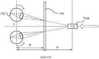
图7A示出了人眼如何在真实世界中经历辐辏和调节的例子。辐辏是两只眼睛在相反方向上的同时运动或旋转以获得或保持双眼单视觉,并被联系到眼睛的调节。在正常条件下,改变眼睛的焦点以看在不同距离处的对象自动引起辐辏和调节。在图7A的例子中,用户正在看真实对象700A(即,用户的眼睛趋向到真实对象700A上,并且来自用户的眼睛的凝视线相交于真实对象700A处)。当如由图7A中的箭头所指示地,真实对象700A移动得更靠近用户时,每只眼睛702向内旋转以保持趋向到真实对象700A上。当真实对象700A变得更近时,眼睛702必须通过改变它的形状减小眼睛702的光焦度或焦距来“适应于”更近的距离。因此,在真实世界的正常条件下,辐辏深度(dv)等于焦距(df)。Figure 7A shows an example of how the human eye experiences convergence and accommodation in the real world. Verge is the simultaneous movement or rotation of the two eyes in opposite directions to achieve or maintain monovision and is linked to the accommodation of the eyes. Under normal conditions, changing the focus of the eye to see objects at different distances automatically induces vergence and accommodation. In the example of FIG. 7A, the user is looking at
然而,图7B示出了对于一些三维显示器可能出现的在辐辏和调节之间的示例冲突。在该例子中,用户正在看显示在3D电子屏幕704上的虚拟对象700B;然而,用户的眼睛趋向在虚拟对象700B上,并且来自用户的眼睛的凝视线相交于虚拟对象700B处,虚拟对象700B在距离用户的眼睛比离3D电子屏幕704的更大距离处。当虚拟对象700B被呈现在3D电子显示器704上以看起来更靠近用户时,每只眼睛702再次向内旋转以保持趋向到虚拟对象700B上,但是每只眼睛的光焦度或焦距没有减小;因此,用户的眼睛不像图7A中的那样适应。因此,代替减小光焦度或焦距以适应于更近的辐辏深度,眼睛702保持在与3D电子显示器704相关联的距离处的调节。因此,对于显示在3D电子显示器上的对象,辐辏深度(dv)常常不等于人眼的焦距(df)。在辐辏深度和焦距之间的这个差异被称为“辐辏-调节冲突”。只经历辐辏或调节而不是两者的用户最终将经历某种程度的疲劳和恶心,这对于虚拟现实系统创建者是不希望有的。可以通过耳机根据辐辏深度(或所预测的辐辏深度)动态地调整光学块的光焦度来调节3D电子屏幕的辐辏的变化。However, Figure 7B shows an example conflict between vergence and accommodation that may arise for some three-dimensional displays. In this example, the user is looking at
因此,为虚拟场景的所呈现的帧调整光学块104的焦距(或光焦度)以提供对所生成的辐辏深度的调节。图8A和图8B示出了用于通过使用变焦元件804改变在电子显示器802和光学块104之间的距离来调节光学块104的焦距的示例过程。在图8A和图8B的例子中,变焦致动块506包括变焦元件804,例如致动器或电动机和轨道806,但是也可以包括使光学块104、电子显示器802(例如802a、802b)或两者能够沿着轨道806移动以动态地调整光学块104的光焦度的其他部件。Accordingly, the focal length (or optical power) of the
图8A示出了为虚拟场景的帧n提供焦点调整的HMD 501的例子。在该例子中,虚拟场景包括显示在电子显示器802a上的对象808,用户800的凝视被引导(即,趋向)到该对象。对象808的虚拟图像位于在电子显示器802a后面离出射光瞳810的虚拟距离di处。在图8A的例子中,光学块104在位置Pi上,这提供了对距离di的调节以实现针对对象806的舒适的观看。Figure 8A shows an example of an
图8B示出了为虚拟场景的后续帧n+1提供焦点调整的HMD 501。在该例子中,当对象808在虚拟场景中快速朝着用户800移动时,用户800可能已经重新定位它的眼睛。因此,对象808的虚拟图像相对靠近电子显示器802b或在电子显示器802b上被定位。响应于对象808更靠近的位置,用户800的眼睛向内旋转以趋向到对象808,使辐辏处理模块512为帧n+1确定新的辐辏深度,并且向变焦致动块506提供新的辐辏深度。基于新的辐辏深度,变焦元件804将光学块104从位置pi移动到新的位置pf以使用户800适应在更近的对象808的新辐辏深度df处。Figure 8B shows
在一个例子中,光学块104的每个状态对应于焦距和眼睛位置的组合,为一定范围的辐辏深度提供调节,并且与光学块104的特定位置相关联。因此,辐辏深度可以映射到光学块104的位置,并存储在查找表中。因此,当从辐辏处理模块512接收到辐辏深度时,变焦致动块506基于查找表来将光学块104自动移动到对应于接收到的辐辏深度的位置。In one example, each state of the
在许多实例中,虚拟现实系统旨在向用户呈现虚拟环境,该虚拟环境紧密地模拟真实世界环境或者向用户提供使用户迷失在由虚拟现实系统创建的幻觉中的内容。为了向用户提供逼真或迷人的虚拟环境,虚拟现实系统实现本文讨论的多个系统和方法以在用户不能察觉到的效率下一起操作。例如,过渡延迟对于用户对虚拟现实系统的体验是特别昂贵的。如果用户正在等待由耳机呈现的虚拟场景以赶上用户的大脑已经预期的东西,幻觉被打破和/或用户可能变得恶心。然而,处理速度和市场上可买到的致动器目前比人眼改变它的晶状体形状和人脑记录晶状体的新形状所聚焦于的东西的协调更快,允许所公开的系统和方法向用户提供高质量的虚拟环境。In many instances, virtual reality systems are designed to present a user with a virtual environment that closely simulates a real-world environment or to provide the user with content that causes the user to lose themselves in the illusion created by the virtual reality system. In order to provide a user with a realistic or captivating virtual environment, a virtual reality system implements the various systems and methods discussed herein to operate together with an efficiency that is imperceptible to the user. For example, transition delays are particularly expensive for a user's experience with a virtual reality system. If the user is waiting for the virtual scene presented by the headset to catch up with what the user's brain is already anticipating, the illusion is broken and/or the user may become nauseous. However, processing speed and commercially available actuators are currently faster than the coordination of the human eye to change its lens shape and the human brain to record what the new shape of the lens is focused on, allowing the disclosed systems and methods to provide users with access to Provides a high-quality virtual environment.
回来参考图8A和图8B,为了提供对新辐辏深度的调节同时也留出时间来执行额外的计算而用户没有察觉到延迟,变焦元件804移动光学块104的速度受到人眼执行调节的速率的限制。例如,假设人眼调节具有10屈光度/sec峰值速度、100屈光度/sec2峰值加速度,并且改变在电子显示器802和光学块104之间的距离将虚拟图像移动大约0.5屈光度/mm,变焦元件804以10/0.5=20mm/sec的最小速度和100/0.5=200mm/sec2加速度的最小加速度操作以防止用户察觉到光学块104相对于电子显示器102的重新定位。存在满足上述值的市场上可买到的致动器。Referring back to Figures 8A and 8B, in order to provide an adjustment to the new vergence depth while also allowing time to perform additional calculations without the user perceiving the delay, the speed at which the
此外,可以基于用户的观看位置来确定场景的景深模糊。为了确定景深模糊,确定在由HMD 501呈现给用户的场景内的用户的凝视被引导到的点,并且光学块104被配置为其中用户的凝视被引导到的在场景内的点处于用户的焦点上的状态。然后,相对于在场景中的用户的凝视被引导到的点来确定景深模糊。在一个例子中,与辐辏深度相对应的场景几何结构内的深度(例如,在虚拟场景内的距离)被确定为虚拟场景的帧的焦平面。因此,在虚拟场景内具有大于或小于焦平面离用户的眼睛的距离的距离的虚拟环境的对象或特征可以用合成模糊来呈现。在另一个例子中,基于在与辐辏深度对应的深度处场景中用户的凝视聚焦于的对象(即,“聚焦对象”)来确定景深模糊。因此,聚焦对象而不是焦平面提供参考点以识别在场景中的以景深模糊呈现的其他对象,即使其他对象在场景中具有与聚焦对象相似的深度。Furthermore, the depth of field blur of the scene may be determined based on the viewing position of the user. To determine the depth of field blur, a point within the scene presented to the user by the
模糊可以是渐进的,具有基于对象或特征离焦平面(或聚焦对象)的距离而应用于对象或特征的模糊的级别,或者大致均匀级别的模糊可以应用于在虚拟场景中的对象或特征。景深模糊是双眼视觉的自然结果,因此在虚拟场景中包括景深模糊通过向用户提供预期的深度提示促进了虚拟场景的幻觉,这可以增强用户对虚拟场景的体验。此外,模糊可以至少部分地基于用户的眼睛的所测量的属性。例如,用户的眼睛的波前像差可以由波前像差计测量,景深模糊至少部分地基于所测量的波前像差。用户的眼睛的示例波前像差可以包括通常不由眼镜、隐形眼镜或屈光手术矫正的高阶像差。在确定景深模糊时考虑到用户的眼睛的属性可以提高在观看场景时的用户舒适度。The blur may be progressive, with a level of blur applied to an object or feature based on its distance from the focal plane (or focused object), or a substantially uniform level of blur may be applied to an object or feature in a virtual scene. Depth-of-field blur is a natural consequence of binocular vision, so the inclusion of depth-of-field blur in a virtual scene facilitates the illusion of a virtual scene by providing the user with an expected depth cue, which can enhance the user's experience with the virtual scene. Furthermore, the blurring may be based at least in part on measured properties of the user's eyes. For example, the wavefront aberration of the user's eye may be measured by a wavefront aberrometer, and the depth of field blur is based at least in part on the measured wavefront aberration. Example wavefront aberrations of a user's eye may include higher order aberrations that are not typically corrected by glasses, contact lenses, or refractive surgery. Taking into account the properties of the user's eyes when determining the depth-of-field blur can improve user comfort when viewing a scene.
对应于正在由用户观看的虚拟场景的部分的虚拟场景的帧在有失真校正以校正由光学块104的所确定的状态引起的光学误差的情况下以及在有基于辐辏深度的景深模糊的情况下被显示在电子显示器102上。此外,变焦致动块506改变了光学块104的焦点以提供对用户的眼睛被趋向的虚拟场景的部分中的位置的聚焦和调节。Frames of the virtual scene corresponding to the portion of the virtual scene being viewed by the user with distortion correction to correct for optical errors caused by the determined state of the
附加配置信息Additional configuration information
为了说明的目的,提出了实施例的前述描述;它并没有被规定为无遗漏的或将专利权限制到所公开的精确形式。相关领域中的技术人员可以认识到,根据上述公开,许多修改和变化是可能的。The foregoing description of the embodiments has been presented for purposes of illustration; it is not intended to be exhaustive or to limit patent rights to the precise form disclosed. Those skilled in the relevant art will appreciate that many modifications and variations are possible in light of the above disclosure.
在说明书中使用的语言主要为了可读性和教学目的而被选择,并且它可没有被选择来描绘或限制创造性主题。因此,意图是本专利权的范围并不被该详细描述限制,而是被在基于此的申请上发布的任何权利要求限制。因此,实施例的公开被规定为是说明性的,但不是专利权的范围的限制。The language used in the specification has been selected primarily for readability and instructional purposes, and it may not have been selected to delineate or limit the inventive subject matter. Therefore, it is intended that the scope of the patent rights be limited not by this detailed description, but by any claims issued on applications based thereon. Accordingly, the disclosure of the embodiments is intended to be illustrative, and not limiting of the scope of patent rights.
Claims (19)
Priority Applications (1)
| Application Number | Priority Date | Filing Date | Title |
|---|---|---|---|
| CN202210141252.0ACN114326128B (en) | 2017-02-21 | 2018-02-20 | Focus adjustment for multi-plane head mounted displays |
Applications Claiming Priority (5)
| Application Number | Priority Date | Filing Date | Title |
|---|---|---|---|
| US201762461451P | 2017-02-21 | 2017-02-21 | |
| US62/461,451 | 2017-02-21 | ||
| CN202210141252.0ACN114326128B (en) | 2017-02-21 | 2018-02-20 | Focus adjustment for multi-plane head mounted displays |
| PCT/US2018/018860WO2018156523A1 (en) | 2017-02-21 | 2018-02-20 | Focus adjusting multiplanar head mounted display |
| CN201880013205.XACN110325895B (en) | 2017-02-21 | 2018-02-20 | Focus Adjustment for Multi-Plane Head Mounted Displays |
Related Parent Applications (1)
| Application Number | Title | Priority Date | Filing Date |
|---|---|---|---|
| CN201880013205.XADivisionCN110325895B (en) | 2017-02-21 | 2018-02-20 | Focus Adjustment for Multi-Plane Head Mounted Displays |
Publications (2)
| Publication Number | Publication Date |
|---|---|
| CN114326128Atrue CN114326128A (en) | 2022-04-12 |
| CN114326128B CN114326128B (en) | 2024-11-15 |
Family
ID=63167133
Family Applications (2)
| Application Number | Title | Priority Date | Filing Date |
|---|---|---|---|
| CN202210141252.0AActiveCN114326128B (en) | 2017-02-21 | 2018-02-20 | Focus adjustment for multi-plane head mounted displays |
| CN201880013205.XAActiveCN110325895B (en) | 2017-02-21 | 2018-02-20 | Focus Adjustment for Multi-Plane Head Mounted Displays |
Family Applications After (1)
| Application Number | Title | Priority Date | Filing Date |
|---|---|---|---|
| CN201880013205.XAActiveCN110325895B (en) | 2017-02-21 | 2018-02-20 | Focus Adjustment for Multi-Plane Head Mounted Displays |
Country Status (4)
| Country | Link |
|---|---|
| US (2) | US10866418B2 (en) |
| EP (2) | EP3485319B1 (en) |
| CN (2) | CN114326128B (en) |
| WO (1) | WO2018156523A1 (en) |
Families Citing this family (39)
| Publication number | Priority date | Publication date | Assignee | Title |
|---|---|---|---|---|
| US9132352B1 (en) | 2010-06-24 | 2015-09-15 | Gregory S. Rabin | Interactive system and method for rendering an object |
| US10962780B2 (en)* | 2015-10-26 | 2021-03-30 | Microsoft Technology Licensing, Llc | Remote rendering for virtual images |
| EP3485319B1 (en)* | 2017-02-21 | 2025-07-16 | Meta Platforms Technologies, LLC | Focus adjusting multiplanar head mounted display |
| WO2019034236A1 (en)* | 2017-08-14 | 2019-02-21 | Huawei Technologies Co., Ltd. | Device and method for pre-compensating a fast tunable lens |
| US10546430B1 (en)* | 2017-08-29 | 2020-01-28 | Facebook Technologies, Llc | Image plane adjustment in a near-eye display |
| US10698204B1 (en)* | 2017-10-16 | 2020-06-30 | Facebook Technologies, Llc | Immersed hot mirrors for illumination in eye tracking |
| US10634913B2 (en)* | 2018-01-22 | 2020-04-28 | Symbol Technologies, Llc | Systems and methods for task-based adjustable focal distance for heads-up displays |
| US10747309B2 (en)* | 2018-05-10 | 2020-08-18 | Microsoft Technology Licensing, Llc | Reconfigurable optics for switching between near-to-eye display modes |
| US20200049994A1 (en)* | 2018-08-13 | 2020-02-13 | Google Llc | Tilted focal plane for near-eye display system |
| KR102750454B1 (en)* | 2018-08-21 | 2025-01-07 | 삼성전자주식회사 | Wearable device and controlling method thereof |
| FR3086399B1 (en)* | 2018-09-24 | 2021-09-17 | Commissariat Energie Atomique | VIRTUAL OR AUGMENTED REALITY VISION SYSTEM WITH EYE IMAGE SENSOR, AND RELATED METHOD |
| US10886702B2 (en)* | 2018-11-09 | 2021-01-05 | Facebook Technologies, Llc | Vertical-cavity surface-emitting laser for near-field illumination of an eye |
| US11009713B1 (en)* | 2018-12-12 | 2021-05-18 | Facebook Technologies, Llc | Head-mounted display device with voice coil motors for moving displays |
| US11454779B1 (en)* | 2018-12-12 | 2022-09-27 | Meta Platforms Technologies, Llc | Head-mounted display device with stepper motors for moving displays |
| US10871627B1 (en) | 2018-12-12 | 2020-12-22 | Facebook Technologies, Llc | Head-mounted display device with direct-current (DC) motors for moving displays |
| IL318088A (en)* | 2019-01-10 | 2025-02-01 | 6 OVER 6 VISION Ltd | Apparatus, system, and method of determining one or more parameters of a lens |
| KR102149732B1 (en)* | 2019-04-17 | 2020-08-31 | 라쿠텐 인코포레이티드 | Display control device, display control method, program, and non-transitory computer-readable information recording medium |
| US11586024B1 (en) | 2019-08-05 | 2023-02-21 | Meta Platforms Technologies, Llc | Peripheral see-through pancake lens assembly and display device with same |
| US11579425B1 (en) | 2019-08-05 | 2023-02-14 | Meta Platforms Technologies, Llc | Narrow-band peripheral see-through pancake lens assembly and display device with same |
| EP4024120B1 (en)* | 2019-08-26 | 2024-12-04 | BOE Technology Group Co., Ltd. | Optical display system and method, and display device |
| US11467332B2 (en) | 2019-09-10 | 2022-10-11 | Meta Platforms Technologies, Llc | Display with switchable retarder array |
| US11726336B2 (en) | 2019-09-10 | 2023-08-15 | Meta Platforms Technologies, Llc | Active zonal display illumination using a chopped lightguide |
| US10989928B2 (en) | 2019-09-17 | 2021-04-27 | Facebook Technologies, Llc | Thin see-through pancake lens assembly and display device including the same |
| US10989927B2 (en)* | 2019-09-19 | 2021-04-27 | Facebook Technologies, Llc | Image frame synchronization in a near eye display |
| US11391906B2 (en)* | 2019-11-06 | 2022-07-19 | Valve Corporation | Optical system for head-mounted display device |
| US11132056B2 (en)* | 2019-12-04 | 2021-09-28 | Facebook Technologies, Llc | Predictive eye tracking systems and methods for foveated rendering for electronic displays |
| US11217024B2 (en)* | 2019-12-26 | 2022-01-04 | Facebook Technologies, Llc | Artificial reality system with varifocal display of artificial reality content |
| US11360308B2 (en) | 2020-01-22 | 2022-06-14 | Facebook Technologies, Llc | Optical assembly with holographic optics for folded optical path |
| US11243399B2 (en)* | 2020-01-31 | 2022-02-08 | Microsoft Technology Licensing, Llc | Head mounted display device with double faceted optics |
| US11209676B2 (en)* | 2020-04-15 | 2021-12-28 | Facebook Technologies, Llc | Local dimming in a device |
| CN114675417A (en)* | 2020-12-24 | 2022-06-28 | 华为技术有限公司 | Display module and virtual image position adjusting method and device |
| CN112595496B (en)* | 2020-12-31 | 2023-04-21 | 深圳惠牛科技有限公司 | Method, device, equipment and storage medium for detecting faults of near-eye display equipment |
| CN115407504B (en)* | 2021-05-27 | 2025-09-19 | 华为技术有限公司 | Virtual display device and virtual display method |
| CN113419350B (en)* | 2021-06-18 | 2023-05-23 | 深圳市腾讯计算机系统有限公司 | Virtual reality display device, picture presentation method, device and storage medium |
| CN113376841A (en)* | 2021-07-06 | 2021-09-10 | 业成科技(成都)有限公司 | Display system |
| CN114527876B (en)* | 2022-02-18 | 2024-12-10 | 上海弘博瑞光学科技有限公司 | Focus adjustment method, system, controller and storage medium for virtual reality head display |
| EP4459360A1 (en)* | 2023-05-03 | 2024-11-06 | BAE SYSTEMS plc | Display device for a user -mountable display system |
| WO2024228015A1 (en)* | 2023-05-03 | 2024-11-07 | Bae Systems Plc | Display device for a user-mountable display system |
| US12436391B2 (en) | 2023-10-10 | 2025-10-07 | Meat Platforms Technologies, LLC | Displays with vergence distance for extended reality devices |
Citations (5)
| Publication number | Priority date | Publication date | Assignee | Title |
|---|---|---|---|---|
| US20090295683A1 (en)* | 2008-05-27 | 2009-12-03 | Randall Pugh | Head mounted display with variable focal length lens |
| US20110075257A1 (en)* | 2009-09-14 | 2011-03-31 | The Arizona Board Of Regents On Behalf Of The University Of Arizona | 3-Dimensional electro-optical see-through displays |
| US8705177B1 (en)* | 2011-12-05 | 2014-04-22 | Google Inc. | Integrated near-to-eye display module |
| WO2016105521A1 (en)* | 2014-12-23 | 2016-06-30 | Meta Company | Apparatuses, methods and systems coupling visual accommodation and visual convergence to the same plane at any depth of an object of interest |
| CN110325895A (en)* | 2017-02-21 | 2019-10-11 | 脸谱科技有限责任公司 | Focus adjustment multi-plane head-mounted display |
Family Cites Families (11)
| Publication number | Priority date | Publication date | Assignee | Title |
|---|---|---|---|---|
| US20060210111A1 (en) | 2005-03-16 | 2006-09-21 | Dixon Cleveland | Systems and methods for eye-operated three-dimensional object location |
| US8410733B2 (en)* | 2009-04-02 | 2013-04-02 | Indian Institute Of Science | Wound field synchronous motor drive |
| US9292973B2 (en)* | 2010-11-08 | 2016-03-22 | Microsoft Technology Licensing, Llc | Automatic variable virtual focus for augmented reality displays |
| US20130241805A1 (en)* | 2012-03-15 | 2013-09-19 | Google Inc. | Using Convergence Angle to Select Among Different UI Elements |
| CN102841448B (en)* | 2012-09-13 | 2014-09-10 | 东南大学 | Imaging method of stereoscopic display based on multi-screen imaging |
| JP2014219621A (en)* | 2013-05-10 | 2014-11-20 | 株式会社タイトー | Display device and display control program |
| GB201310379D0 (en) | 2013-06-11 | 2013-07-24 | Sony Comp Entertainment Europe | Head-mountable apparatus and systems |
| EP3149528B1 (en)* | 2014-05-30 | 2023-06-07 | Magic Leap, Inc. | Methods and system for creating focal planes in virtual and augmented reality |
| WO2016204433A1 (en)* | 2015-06-15 | 2016-12-22 | Samsung Electronics Co., Ltd. | Head mounted display apparatus |
| US9921413B2 (en) | 2015-10-02 | 2018-03-20 | Deepsee Inc. | 3D image system, method, and applications |
| US10516879B2 (en)* | 2016-08-12 | 2019-12-24 | Avegant Corp. | Binocular display with digital light path length modulation |
- 2018
- 2018-02-20EPEP18756697.1Apatent/EP3485319B1/enactiveActive
- 2018-02-20CNCN202210141252.0Apatent/CN114326128B/enactiveActive
- 2018-02-20CNCN201880013205.XApatent/CN110325895B/enactiveActive
- 2018-02-20EPEP25189335.0Apatent/EP4610789A2/enactivePending
- 2018-02-20WOPCT/US2018/018860patent/WO2018156523A1/ennot_activeCeased
- 2018-02-20USUS15/900,739patent/US10866418B2/enactiveActive
- 2020
- 2020-01-07USUS16/736,712patent/US10983354B2/enactiveActive
Patent Citations (5)
| Publication number | Priority date | Publication date | Assignee | Title |
|---|---|---|---|---|
| US20090295683A1 (en)* | 2008-05-27 | 2009-12-03 | Randall Pugh | Head mounted display with variable focal length lens |
| US20110075257A1 (en)* | 2009-09-14 | 2011-03-31 | The Arizona Board Of Regents On Behalf Of The University Of Arizona | 3-Dimensional electro-optical see-through displays |
| US8705177B1 (en)* | 2011-12-05 | 2014-04-22 | Google Inc. | Integrated near-to-eye display module |
| WO2016105521A1 (en)* | 2014-12-23 | 2016-06-30 | Meta Company | Apparatuses, methods and systems coupling visual accommodation and visual convergence to the same plane at any depth of an object of interest |
| CN110325895A (en)* | 2017-02-21 | 2019-10-11 | 脸谱科技有限责任公司 | Focus adjustment multi-plane head-mounted display |
Also Published As
| Publication number | Publication date |
|---|---|
| CN114326128B (en) | 2024-11-15 |
| CN110325895B (en) | 2022-02-15 |
| US10866418B2 (en) | 2020-12-15 |
| US10983354B2 (en) | 2021-04-20 |
| US20200142201A1 (en) | 2020-05-07 |
| WO2018156523A1 (en) | 2018-08-30 |
| EP4610789A2 (en) | 2025-09-03 |
| EP3485319A4 (en) | 2020-04-01 |
| CN110325895A (en) | 2019-10-11 |
| EP3485319A1 (en) | 2019-05-22 |
| US20180239145A1 (en) | 2018-08-23 |
| EP3485319B1 (en) | 2025-07-16 |
Similar Documents
| Publication | Publication Date | Title |
|---|---|---|
| CN110325895B (en) | Focus Adjustment for Multi-Plane Head Mounted Displays | |
| US10937129B1 (en) | Autofocus virtual reality headset | |
| US10241569B2 (en) | Focus adjustment method for a virtual reality headset | |
| US11106276B2 (en) | Focus adjusting headset | |
| US10025060B2 (en) | Focus adjusting virtual reality headset | |
| US10317680B1 (en) | Optical aberration correction based on user eye position in head mounted displays | |
| US9984507B2 (en) | Eye tracking for mitigating vergence and accommodation conflicts | |
| US10379356B2 (en) | Accommodation based optical correction | |
| EP3179289B1 (en) | Focus adjusting virtual reality headset | |
| US11906750B1 (en) | Varifocal display with actuated reflectors | |
| US10989927B2 (en) | Image frame synchronization in a near eye display | |
| US20230084541A1 (en) | Compact imaging optics using spatially located, free form optical components for distortion compensation and image clarity enhancement | |
| US10859832B1 (en) | Mitigating light exposure to elements of a focus adjusting head mounted display | |
| US20250067982A1 (en) | Controllable aperture projection for waveguide display | |
| US20250239010A1 (en) | Saccade contingent reduced resolution rendering | |
| CN114594603A (en) | Focal plane display | |
| US10623743B1 (en) | Compression of captured images including light captured from locations on a device or object |
Legal Events
| Date | Code | Title | Description |
|---|---|---|---|
| PB01 | Publication | ||
| PB01 | Publication | ||
| SE01 | Entry into force of request for substantive examination | ||
| SE01 | Entry into force of request for substantive examination | ||
| CB02 | Change of applicant information | ||
| CB02 | Change of applicant information | Address after:California, USA Applicant after:Yuan Platform Technology Co.,Ltd. Address before:California, USA Applicant before:Facebook Technologies, LLC | |
| GR01 | Patent grant | ||
| GR01 | Patent grant |