CN114322866A - Nuclear material board uranium homogeneity detection device - Google Patents
Nuclear material board uranium homogeneity detection deviceDownload PDFInfo
- Publication number
- CN114322866A CN114322866ACN202210121780.XACN202210121780ACN114322866ACN 114322866 ACN114322866 ACN 114322866ACN 202210121780 ACN202210121780 ACN 202210121780ACN 114322866 ACN114322866 ACN 114322866A
- Authority
- CN
- China
- Prior art keywords
- plate
- uranium
- motor
- standard
- detector
- Prior art date
- Legal status (The legal status is an assumption and is not a legal conclusion. Google has not performed a legal analysis and makes no representation as to the accuracy of the status listed.)
- Pending
Links
Images


Classifications
- Y—GENERAL TAGGING OF NEW TECHNOLOGICAL DEVELOPMENTS; GENERAL TAGGING OF CROSS-SECTIONAL TECHNOLOGIES SPANNING OVER SEVERAL SECTIONS OF THE IPC; TECHNICAL SUBJECTS COVERED BY FORMER USPC CROSS-REFERENCE ART COLLECTIONS [XRACs] AND DIGESTS
- Y02—TECHNOLOGIES OR APPLICATIONS FOR MITIGATION OR ADAPTATION AGAINST CLIMATE CHANGE
- Y02E—REDUCTION OF GREENHOUSE GAS [GHG] EMISSIONS, RELATED TO ENERGY GENERATION, TRANSMISSION OR DISTRIBUTION
- Y02E30/00—Energy generation of nuclear origin
- Y02E30/30—Nuclear fission reactors
Landscapes
- Measurement Of Radiation (AREA)
Abstract
Translated fromChinese
Description
Translated fromChinese技术领域technical field
本发明涉及核料板中铀密度值的技术领域,特别是一种核料板铀均匀性检测装置。The invention relates to the technical field of uranium density values in a nuclear material plate, in particular to a uranium uniformity detection device for a nuclear material plate.
背景技术Background technique
核燃料板通常为长条板型,为保证其使用性能,燃料板出厂前需进行芯体核材料分布均匀性检测。现有检测设备虽然可以进行相关性能的评测工作,但是现有设备的自动化程度低,无法实现自动上下料,自动进给等功能更难以实现批量产品的连续检测工作。同时,由于人工介入过程过多,其设备重复性测量误差难以得到控制。因此亟需一种高效高精度自动化的核燃料板铀均匀性检测装置。The nuclear fuel plate is usually a long plate type. In order to ensure its performance, the fuel plate needs to be tested for the distribution uniformity of the core core material before leaving the factory. Although the existing testing equipment can perform related performance evaluation work, the existing equipment has a low degree of automation and cannot realize automatic loading and unloading, and functions such as automatic feeding are more difficult to achieve continuous testing of batch products. At the same time, due to too many manual intervention procedures, it is difficult to control the repeatability measurement error of its equipment. Therefore, an efficient and high-precision automatic detection device for uranium uniformity of nuclear fuel plates is urgently needed.
发明内容SUMMARY OF THE INVENTION
本发明的目的在于克服现有技术的缺点,提供一种结构紧凑、提高铀密度值检测效率、降低检测成本、操作简单的核料板铀均匀性检测装置。The purpose of the present invention is to overcome the shortcomings of the prior art, and to provide a nuclear material plate uranium uniformity detection device with compact structure, improved detection efficiency of uranium density value, lower detection cost and simple operation.
本发明的目的通过以下技术方案来实现:一种核料板铀均匀性检测装置,它包括从左往右顺次设置的进料辊道输送装置、支架和出料辊道输送装置,所述支架的前后端部上分别设置有探测器组件和标定组件,探测器组件设置于进料辊道输送装置的前侧,探测器组件包括直线模组、探测器和γ射线放射源,直线模组设置于支架的顶表面上,直线模组纵向设置,直线模组的滑块上固设有连接架,连接架的后端部上设置有L板,L板的水平板上设置有γ射线放射源,γ射线放射源的准直孔朝下设置,L板的垂直板上设置有探测器,探测器设置于γ射线放射源的正下方,探测器的探头朝上设置,L板的水平板上固设有屏蔽盖驱动电机,屏蔽盖驱动电机的输出轴贯穿水平板设置,且延伸端上固设有活动屏蔽盖,活动屏蔽盖设置于探头和准直孔之间;The object of the present invention is achieved through the following technical solutions: a nuclear material plate uranium uniformity detection device, which includes a feeding roller conveyor, a bracket and a discharging roller conveyor that are sequentially arranged from left to right, and the said The front and rear ends of the bracket are respectively provided with a detector assembly and a calibration assembly. The detector assembly is arranged on the front side of the feeding roller conveyor. The detector assembly includes a linear module, a detector and a gamma ray radiation source. The linear module Set on the top surface of the bracket, the linear module is arranged longitudinally, the slider of the linear module is fixed with a connecting frame, the rear end of the connecting frame is provided with an L plate, and the horizontal plate of the L plate is provided with a gamma ray radiation source, the collimation hole of the γ-ray radiation source is set downward, a detector is set on the vertical plate of the L board, the detector is set directly below the γ-ray radiation source, the probe of the detector is set upward, and the horizontal board of the L board is set A shielding cover driving motor is fixed on the top, the output shaft of the shielding cover driving motor is arranged through the horizontal plate, and a movable shielding cover is fixed on the extension end, and the movable shielding cover is arranged between the probe and the collimation hole;
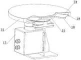
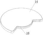
所述标定组件设置于支架的后侧,标定组件包括电机、标准板防护罩和标准板搁置盘,电机垂向设置且固设于支架的顶表面上,标准板防护罩固设于电机机壳的顶表面上,标准板防护罩内设置有密闭腔,标准板防护罩前端部上设置有连通密闭腔的喇叭形缺口,所述电机的输出轴伸入于密闭腔内,且输出轴上安装有标准板搁置盘,标准板搁置盘设置于密闭腔内,标准板搁置盘的外边缘上设置有且沿其圆周方向设置有多组搁置架,其中一组搁置架设置于喇叭形缺口内,每组搁置架均包括两个搁置板,两个搁置板的一端均固设于标准板搁置盘的边缘上,两个搁置板的另一端的内侧面上均设置有台阶面。The calibration component is arranged on the rear side of the bracket, and the calibration component includes a motor, a standard plate protective cover and a standard plate resting plate. The motor is vertically arranged and fixed on the top surface of the bracket, and the standard plate protective cover is fixed on the motor casing. On the top surface of the standard plate protective cover, a sealed cavity is arranged in the standard plate protective cover, and a trumpet-shaped notch is arranged on the front end of the standard plate protective cover to communicate with the sealed cavity. The output shaft of the motor extends into the sealed cavity, and the output shaft is installed on the There is a standard plate shelving plate, the standard plate shelving plate is arranged in a closed cavity, and a plurality of groups of shelving racks are arranged on the outer edge of the standard plate shelving plate and along its circumferential direction, and one group of shelving racks is arranged in the trumpet-shaped gap, Each set of shelves includes two shelf plates, one end of the two shelf plates is fixed on the edge of the standard plate shelf plate, and the inner surface of the other end of the two shelf plates is provided with a step surface.
所述L板的垂直板固设于连接架上。The vertical plate of the L plate is fixed on the connecting frame.
所述直线模组包括伺服电机、机座和滑块,所述伺服电机和机座均固设于支架的顶表面上,机座内旋转安装有纵向设置的丝杆,滑块螺纹连接于丝杆上,伺服电机的输出轴与丝杆的一端经联轴器连接。The linear module includes a servo motor, a base and a slider, the servo motor and the base are fixed on the top surface of the bracket, a longitudinally arranged screw rod is rotatably installed in the base, and the slider is threadedly connected to the screw. On the rod, the output shaft of the servo motor is connected with one end of the lead screw through a coupling.
它还包括工位机,所述工位机与探测器的输出接口电连接。It also includes a work station that is electrically connected to the output interface of the detector.
每组搁置架均匀分布于标准板搁置盘上。Each group of racks is evenly distributed on the standard plate rack.
所述准直孔与探头所形成区域与喇叭形缺口相对立设置。The area formed by the collimation hole and the probe is arranged opposite to the trumpet-shaped notch.
所述进料辊道输送装置的滚筒的顶表面与出料辊道输送装置的滚筒的顶表面平齐。The top surface of the roller of the infeed roller conveyor is flush with the top surface of the roller of the outfeed roller conveyor.
所述电机为步进电机。The motor is a stepping motor.
本发明具有以下优点:本发明结构紧凑、提高铀密度值检测效率、降低检测成本、操作简单。The invention has the following advantages: the structure of the invention is compact, the detection efficiency of the uranium density value is improved, the detection cost is reduced, and the operation is simple.
附图说明Description of drawings
图1为本发明的结构示意图;Fig. 1 is the structural representation of the present invention;
图2为图1的俯视图;Fig. 2 is the top view of Fig. 1;
图3为探头组件的结构示意图;FIG. 3 is a schematic structural diagram of a probe assembly;
图4为探头组件的侧视图;Figure 4 is a side view of the probe assembly;
图5为标定组件的结构示意图;5 is a schematic structural diagram of a calibration assembly;
图6为标准板防护罩的结构示意图;6 is a schematic structural diagram of a standard plate protective cover;
图7为标准板搁置盘的结构示意图;Fig. 7 is the structural representation of standard plate shelving tray;
图8为支架的结构示意图;Fig. 8 is the structural representation of the bracket;
图中,1-进料辊道输送装置,2-支架,3-出料辊道输送装置,4-探测器组件,5-标定组件,6-直线模组,7-探测器,8-γ射线放射源,9-连接架,10-L板,11-屏蔽盖驱动电机,12-活动屏蔽盖,13-电机,14-标准板防护罩,15-标准板搁置盘,16-密闭腔,18-搁置板,19-台阶面,20-伺服电机,21-机座,22-滑块,23-滚筒,24-标准核燃料板,25-待检测核燃料板,26-探头。In the figure, 1-feed roller conveyor, 2-support, 3-discharge roller conveyor, 4-detector assembly, 5-calibration assembly, 6-linear module, 7-detector, 8-γ Radiation source, 9-connecting frame, 10-L board, 11-shield cover drive motor, 12-movable shield cover, 13-motor, 14-standard board protective cover, 15-standard board shelf, 16-airtight cavity, 18- Shelf plate, 19- Step surface, 20- Servo motor, 21- Machine base, 22- Slide block, 23- Roller, 24- Standard nuclear fuel plate, 25- Nuclear fuel plate to be tested, 26- Probe.
具体实施方式Detailed ways
下面结合附图对本发明做进一步的描述,本发明的保护范围不局限于以下所述:The present invention will be further described below in conjunction with the accompanying drawings, and the protection scope of the present invention is not limited to the following:
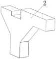
如图1~8所示,一种核料板铀均匀性检测装置,它包括从左往右顺次设置的进料辊道输送装置1、支架2和出料辊道输送装置3,所述支架2的前后端部上分别设置有探测器组件4和标定组件5,探测器组件4设置于进料辊道输送装置1的前侧,探测器组件4包括直线模组6、探测器7和γ射线放射源8,直线模组6设置于支架2的顶表面上,直线模组6纵向设置,直线模组6的滑块22上固设有连接架9,连接架9的后端部上设置有L板10,L板10的垂直板固设于连接架9上,L板10的水平板上设置有γ射线放射源8,γ射线放射源8的准直孔朝下设置,L板10的垂直板上设置有探测器7,探测器7设置于γ射线放射源8的正下方,探测器7的探头26朝上设置,L板10的水平板上固设有屏蔽盖驱动电机11,屏蔽盖驱动电机11的输出轴贯穿水平板设置,且延伸端上固设有活动屏蔽盖12,活动屏蔽盖12设置于探头26和准直孔之间。As shown in Figures 1 to 8, a nuclear material plate uranium uniformity detection device includes a feed roller conveyor device 1, a
所述标定组件5设置于支架2的后侧,标定组件5包括电机13、标准板防护罩14和标准板搁置盘15,电机13为步进电机,电机13垂向设置且固设于支架2的顶表面上,标准板防护罩14固设于电机13机壳的顶表面上,标准板防护罩14内设置有密闭腔16,标准板防护罩14前端部上设置有连通密闭腔16的喇叭形缺口,所述电机13的输出轴伸入于密闭腔16内,且输出轴上安装有标准板搁置盘15,标准板搁置盘15设置于密闭腔16内,标准板搁置盘15的外边缘上设置有且沿其圆周方向设置有多组搁置架,每组搁置架均匀分布于标准板搁置盘15上,其中一组搁置架设置于喇叭形缺口内,每组搁置架均包括两个搁置板18,两个搁置板18的一端均固设于标准板搁置盘15的边缘上,两个搁置板18的另一端的内侧面上均设置有台阶面19。The
所述直线模组6包括伺服电机20、机座21和滑块22,所述伺服电机20和机座21均固设于支架2的顶表面上,机座21内旋转安装有纵向设置的丝杆,滑块22螺纹连接于丝杆上,伺服电机20的输出轴与丝杆的一端经联轴器连接。所述准直孔与探头26所形成区域与喇叭形缺口相对立设置The
它还包括工位机,所述工位机与探测器7的输出接口电连接,所述进料辊道输送装置1的滚筒23的顶表面与出料辊道输送装置3的滚筒23的顶表面平齐。It also includes a workstation, which is electrically connected to the output interface of the
本发明的工作过程如下:The working process of the present invention is as follows:
S1、标准核燃料板的标定,其具体步骤为:S1. The calibration of the standard nuclear fuel plate, the specific steps are:
S11、操作人员将已知铀密度值的标准核燃料板24放置于位于喇叭形缺口处的搁置架的两个台阶面19上,两个搁置板18将标准核燃料板24支撑住;S11. The operator places the standard
S12、操作人员打开电机13,电机13带动标准板搁置盘15转动一定角度,以使下一个空搁置架进入到喇叭形缺口内,到位后,操作人员将另一个已知铀密度值的标准核燃料板放置于该空搁置架上;S12. The operator turns on the
S13、操作人员重复步骤S11~S12的操作,即可将具有不同铀密度值的标准核燃料板分别放置于各个搁置架上;S13, the operator repeats the operations of steps S11-S12, and then the standard nuclear fuel plates with different uranium density values can be placed on each shelf respectively;
S14、操作人员打开伺服电机20,伺服电机20带动丝杆转动,滑块22沿着丝杆向后运动,当位于喇叭形缺口内的标准核燃料板24进入到探头26与准直孔所形成的区域后,操作人员关闭伺服电机20;S14. The operator turns on the
S15、操作人员打开屏蔽盖驱动电机11,屏蔽盖驱动电机11带动活动屏蔽盖12转动一定角度,到位后关闭屏蔽盖驱动电机11,此时γ射线放射源8放射出的γ射线穿过标准核燃料板24,此时探测器7接收透射到标准核燃料板24下方的透射γ射线数量,随后探测器7将透射γ射线数量转换成电信号传递给上位机;S15. The operator opens the shielding
S16、操作人员打开电机13,电机13带动标准板搁置盘15转动一定角度,标准板搁置盘15将其上的第二个标准核燃料板转运到喇叭形缺口处,重复步骤S15的步骤,探测器7将第二个标准核燃料板所对应的透射γ射线数量转换成电信号并传递给上位机;S16, the operator turns on the
S17、重复步骤S16的操作多次,即可在上位机中得到不同铀密度值的标准核燃料板与透射γ射线数量的对应关系,以此关系为基础利用最小二乘法拟合出透射γ射线数量值与铀密度值的关系式,且拟合出映射关系式,从而最终实现了标准核燃料板的标定;S17. Repeat the operation of step S16 several times to obtain the corresponding relationship between the standard nuclear fuel plates with different uranium density values and the number of transmitted γ-rays in the host computer. Based on this relationship, the least squares method is used to fit the number of transmitted γ-rays. The relationship between the value and the uranium density value, and the mapping relationship is fitted, so that the calibration of the standard nuclear fuel plate is finally realized;
S2、待检测核燃料板铀密度值的检测,其具体步骤为:S2. The specific steps for the detection of the uranium density value of the nuclear fuel plate to be detected are:
S21、操作人员控制伺服电机20反转,伺服电机20带动丝杆反转,滑块22沿着丝杆向前运动,当探头26与准直孔所形成区域处于进料辊道输送装置1的滚筒23和出料辊道输送装置3的滚筒23之间时,操作人员关闭伺服电机20;S21, the operator controls the
S22、操作人员打开进料辊道输送装置1和出料辊道输送装置3,进料辊道输送装置1和出料辊道输送装置3中的各个滚筒23均做顺时针转动;S22, the operator opens the feeding roller conveyor device 1 and the discharging
S23、操作人员将待检测核燃料板放置于进料辊道输送装置1的滚筒23上,滚筒23将待检测核燃料板25从左往右输送,当待检测核燃料板穿过探头26与准直孔所形成区域后,待检测核燃料板运动到出料辊道输送装置3的滚筒23上,滚筒23将检测后的待检测核燃料板输送出来,其中,待检测核燃料板进入准直孔与探头26所形成区域时,γ射线放射源8放射出的γ射线穿过待检测核燃料板,探测器7接收透射到待检测核燃料板下方的透射γ射线数量,同时探测器7将透射γ射线数量转换成电信号传递给上位机,利用步骤S17中的映射关系式,即可反求出该待检测核燃料板的铀密度值,即可检测出其面板上铀均匀性;因此无需价格昂贵的探测设备来进行检测,通过该检测装置同样能够进行检测,极大的节省了检测成本。S23. The operator places the nuclear fuel plate to be inspected on the
S24、操作人员重复步骤S23即可连续的多个待检测核燃料板的铀密度值进行检测,相比传统检测时,需要消耗大量时间工装定位待检测核燃料板,该检测装置极大的缩短了检测时间,同时实现了连续进行检测,极大的提高了核燃料板铀密度值的检测效率。S24. The operator can repeat step S23 to continuously detect the uranium density values of the nuclear fuel plates to be detected. Compared with the traditional detection, it takes a lot of time to position the nuclear fuel plates to be detected. The detection device greatly shortens the detection time. At the same time, continuous detection is realized, which greatly improves the detection efficiency of the uranium density value of the nuclear fuel plate.
最后应说明的是:以上所述仅为本发明的优选实施例而已,并不用于限制本发明,尽管参照前述实施例对本发明进行了详细的说明,对于本领域的技术人员来说,其依然可以对前述各实施例所记载的技术方案进行修改,或者对其中部分技术特征进行等同替换。凡在本发明的精神和原则之内,所作的任何修改、等同替换、改进等,均应包含在本发明的保护范围之内。Finally, it should be noted that the above descriptions are only preferred embodiments of the present invention, and are not intended to limit the present invention. Although the present invention has been described in detail with reference to the foregoing embodiments, for those skilled in the art, the The technical solutions described in the foregoing embodiments may be modified, or some technical features thereof may be equivalently replaced. Any modification, equivalent replacement, improvement, etc. made within the spirit and principle of the present invention shall be included within the protection scope of the present invention.
Claims (8)
Translated fromChinesePriority Applications (1)
| Application Number | Priority Date | Filing Date | Title |
|---|---|---|---|
| CN202210121780.XACN114322866A (en) | 2022-02-09 | 2022-02-09 | Nuclear material board uranium homogeneity detection device |
Applications Claiming Priority (1)
| Application Number | Priority Date | Filing Date | Title |
|---|---|---|---|
| CN202210121780.XACN114322866A (en) | 2022-02-09 | 2022-02-09 | Nuclear material board uranium homogeneity detection device |
Publications (1)
| Publication Number | Publication Date |
|---|---|
| CN114322866Atrue CN114322866A (en) | 2022-04-12 |
Family
ID=81030105
Family Applications (1)
| Application Number | Title | Priority Date | Filing Date |
|---|---|---|---|
| CN202210121780.XAPendingCN114322866A (en) | 2022-02-09 | 2022-02-09 | Nuclear material board uranium homogeneity detection device |
Country Status (1)
| Country | Link |
|---|---|
| CN (1) | CN114322866A (en) |
Cited By (1)
| Publication number | Priority date | Publication date | Assignee | Title |
|---|---|---|---|---|
| CN117007464A (en)* | 2023-07-21 | 2023-11-07 | 深圳市大成精密设备股份有限公司 | Ray measurement equipment and portable calibration device |
Citations (13)
| Publication number | Priority date | Publication date | Assignee | Title |
|---|---|---|---|---|
| US4822552A (en)* | 1987-02-25 | 1989-04-18 | Westinghouse Electric Corp. | Method and apparatus for passively gamma scanning a nuclear fuel rod |
| CN101587052A (en)* | 2009-06-15 | 2009-11-25 | 浙江大学 | Device and method for testing density, concentration and thickness based on X-ray |
| RU2458416C2 (en)* | 2010-11-15 | 2012-08-10 | Открытое акционерное общество "Машиностроительный завод" | Nuclear fuel pellet density monitoring plant |
| CN203785987U (en)* | 2014-02-22 | 2014-08-20 | 南京必福斯核技术有限公司 | Improved nuclear radiation density detector |
| ES2551290A1 (en)* | 2014-05-14 | 2015-11-17 | Tecnatom, S. A. | Densitometer for density measurement of nuclear fuel rods (Machine-translation by Google Translate, not legally binding) |
| CN205701521U (en)* | 2016-06-08 | 2016-11-23 | 郑州立子加速器科技有限公司 | A kind of gamma-rays Nicotiana tabacum L. screening plant |
| CN106546510A (en)* | 2017-01-09 | 2017-03-29 | 唐山市神州机械有限公司 | It is a kind of based on material density come the method and apparatus of screened coal and gangue |
| CN106935293A (en)* | 2015-12-30 | 2017-07-07 | 韩电原子力燃料株式会社 | Nuclear fuel rod density measuring equipment |
| CN207181215U (en)* | 2017-03-22 | 2018-04-03 | 天津希福科技有限公司 | A kind of nuclear radiation density detection system |
| CN109668533A (en)* | 2019-01-30 | 2019-04-23 | 佛山市宗生科技有限公司 | A kind of automatic calibration device and its scaling method using ray |
| CN110031359A (en)* | 2019-04-08 | 2019-07-19 | 深圳鸿鹏新能源科技有限公司 | The scaling method of surface density measuring instrument |
| CN111880213A (en)* | 2020-08-14 | 2020-11-03 | 兰州大学 | Nuclear fuel rod based on D-D neutron source235U enrichment degree and uniformity detection method |
| CN216668631U (en)* | 2022-02-09 | 2022-06-03 | 四川同人精工科技有限公司 | Nuclear material board uranium homogeneity detection device |
- 2022
- 2022-02-09CNCN202210121780.XApatent/CN114322866A/enactivePending
Patent Citations (13)
| Publication number | Priority date | Publication date | Assignee | Title |
|---|---|---|---|---|
| US4822552A (en)* | 1987-02-25 | 1989-04-18 | Westinghouse Electric Corp. | Method and apparatus for passively gamma scanning a nuclear fuel rod |
| CN101587052A (en)* | 2009-06-15 | 2009-11-25 | 浙江大学 | Device and method for testing density, concentration and thickness based on X-ray |
| RU2458416C2 (en)* | 2010-11-15 | 2012-08-10 | Открытое акционерное общество "Машиностроительный завод" | Nuclear fuel pellet density monitoring plant |
| CN203785987U (en)* | 2014-02-22 | 2014-08-20 | 南京必福斯核技术有限公司 | Improved nuclear radiation density detector |
| ES2551290A1 (en)* | 2014-05-14 | 2015-11-17 | Tecnatom, S. A. | Densitometer for density measurement of nuclear fuel rods (Machine-translation by Google Translate, not legally binding) |
| CN106935293A (en)* | 2015-12-30 | 2017-07-07 | 韩电原子力燃料株式会社 | Nuclear fuel rod density measuring equipment |
| CN205701521U (en)* | 2016-06-08 | 2016-11-23 | 郑州立子加速器科技有限公司 | A kind of gamma-rays Nicotiana tabacum L. screening plant |
| CN106546510A (en)* | 2017-01-09 | 2017-03-29 | 唐山市神州机械有限公司 | It is a kind of based on material density come the method and apparatus of screened coal and gangue |
| CN207181215U (en)* | 2017-03-22 | 2018-04-03 | 天津希福科技有限公司 | A kind of nuclear radiation density detection system |
| CN109668533A (en)* | 2019-01-30 | 2019-04-23 | 佛山市宗生科技有限公司 | A kind of automatic calibration device and its scaling method using ray |
| CN110031359A (en)* | 2019-04-08 | 2019-07-19 | 深圳鸿鹏新能源科技有限公司 | The scaling method of surface density measuring instrument |
| CN111880213A (en)* | 2020-08-14 | 2020-11-03 | 兰州大学 | Nuclear fuel rod based on D-D neutron source235U enrichment degree and uniformity detection method |
| CN216668631U (en)* | 2022-02-09 | 2022-06-03 | 四川同人精工科技有限公司 | Nuclear material board uranium homogeneity detection device |
Cited By (1)
| Publication number | Priority date | Publication date | Assignee | Title |
|---|---|---|---|---|
| CN117007464A (en)* | 2023-07-21 | 2023-11-07 | 深圳市大成精密设备股份有限公司 | Ray measurement equipment and portable calibration device |
Similar Documents
| Publication | Publication Date | Title |
|---|---|---|
| JPS62257092A (en) | Fuel assembly inspection equipment | |
| CN103743975A (en) | Flexible printed circuit board automatic testing equipment and flexible printed circuit board automatic testing method | |
| CN111289959A (en) | A radar automatic intelligent production system | |
| CN114322866A (en) | Nuclear material board uranium homogeneity detection device | |
| WO2023216739A1 (en) | Multi-level staggered material box storage apparatus,material discharge and sorting device, and sorting system | |
| CN216668631U (en) | Nuclear material board uranium homogeneity detection device | |
| CN109459084A (en) | Plug electron-like element detects marking equipment automatically | |
| CN210449709U (en) | Weighing device for dispensing in optical communication industry and control system thereof | |
| CN114210595B (en) | X-RAY thick electric core four corners check out test set | |
| CN108445372A (en) | A kind of diode behavior testing agency for pressing from both sides weldering detection device | |
| CN207741705U (en) | A kind of small-sized lithium cell detects thickness-measuring equipment automatically | |
| CN111273245A (en) | A radar obscura test device | |
| CN203643535U (en) | Soft board automatic test device | |
| CN210358132U (en) | Thickness measuring equipment | |
| CN205301597U (en) | Low background liquid scintillation spectrometer measuring device | |
| CN102890251B (en) | Automatic detecting and sorting device for parameters of coil rack of wave detector | |
| CN117066164A (en) | An automatic screening system for scintillation crystals | |
| CN203664210U (en) | Soft board test device | |
| CN108717200A (en) | A kind of radioactive sample activity multichannel automatic measuring system | |
| CN206726785U (en) | Rectangular narrow channel thermal neutron fluence rate measuring system | |
| CN108414927B (en) | Detection method based on automatic switch detection equipment | |
| CN217331076U (en) | Nuclear material plate cladding thickness detection device | |
| CN110586518B (en) | Full-bag type grain radioactivity detection device | |
| CN103736676A (en) | Automatic discharging device of soft plate | |
| CN103736667A (en) | Flexible board testing device |
Legal Events
| Date | Code | Title | Description |
|---|---|---|---|
| PB01 | Publication | ||
| PB01 | Publication | ||
| SE01 | Entry into force of request for substantive examination | ||
| SE01 | Entry into force of request for substantive examination |