CN114313774A - Material processing device - Google Patents
Material processing deviceDownload PDFInfo
- Publication number
- CN114313774A CN114313774ACN202111187726.7ACN202111187726ACN114313774ACN 114313774 ACN114313774 ACN 114313774ACN 202111187726 ACN202111187726 ACN 202111187726ACN 114313774 ACN114313774 ACN 114313774A
- Authority
- CN
- China
- Prior art keywords
- conveyor belt
- material processing
- proximal end
- processing device
- hinge
- Prior art date
- Legal status (The legal status is an assumption and is not a legal conclusion. Google has not performed a legal analysis and makes no representation as to the accuracy of the status listed.)
- Pending
Links
- 239000000463materialSubstances0.000titleclaimsabstractdescription99
- 230000005484gravityEffects0.000claimsabstractdescription12
- 229910052500inorganic mineralInorganic materials0.000claimsabstractdescription6
- 239000011707mineralSubstances0.000claimsabstractdescription6
- 238000012216screeningMethods0.000claimsdescription25
- 230000008878couplingEffects0.000claimsdescription16
- 238000010168coupling processMethods0.000claimsdescription16
- 238000005859coupling reactionMethods0.000claimsdescription16
- 230000005540biological transmissionEffects0.000claimsdescription11
- 230000000087stabilizing effectEffects0.000claimsdescription7
- 239000011435rockSubstances0.000description5
- 230000006641stabilisationEffects0.000description5
- 238000011105stabilizationMethods0.000description5
- 239000000969carrierSubstances0.000description3
- 238000010276constructionMethods0.000description3
- 239000008187granular materialSubstances0.000description3
- 239000013590bulk materialSubstances0.000description2
- 238000009434installationMethods0.000description2
- 238000010586diagramMethods0.000description1
- 230000013011matingEffects0.000description1
- 239000002184metalSubstances0.000description1
- 238000000034methodMethods0.000description1
- 230000002787reinforcementEffects0.000description1
- 238000007873sievingMethods0.000description1
- 239000000725suspensionSubstances0.000description1
Images


Classifications
- B—PERFORMING OPERATIONS; TRANSPORTING
- B02—CRUSHING, PULVERISING, OR DISINTEGRATING; PREPARATORY TREATMENT OF GRAIN FOR MILLING
- B02C—CRUSHING, PULVERISING, OR DISINTEGRATING IN GENERAL; MILLING GRAIN
- B02C21/00—Disintegrating plant with or without drying of the material
- B02C21/02—Transportable disintegrating plant
- B—PERFORMING OPERATIONS; TRANSPORTING
- B02—CRUSHING, PULVERISING, OR DISINTEGRATING; PREPARATORY TREATMENT OF GRAIN FOR MILLING
- B02C—CRUSHING, PULVERISING, OR DISINTEGRATING IN GENERAL; MILLING GRAIN
- B02C23/00—Auxiliary methods or auxiliary devices or accessories specially adapted for crushing or disintegrating not provided for in preceding groups or not specially adapted to apparatus covered by a single preceding group
- B02C23/02—Feeding devices
- B—PERFORMING OPERATIONS; TRANSPORTING
- B02—CRUSHING, PULVERISING, OR DISINTEGRATING; PREPARATORY TREATMENT OF GRAIN FOR MILLING
- B02C—CRUSHING, PULVERISING, OR DISINTEGRATING IN GENERAL; MILLING GRAIN
- B02C23/00—Auxiliary methods or auxiliary devices or accessories specially adapted for crushing or disintegrating not provided for in preceding groups or not specially adapted to apparatus covered by a single preceding group
- B02C23/08—Separating or sorting of material, associated with crushing or disintegrating
- B—PERFORMING OPERATIONS; TRANSPORTING
- B65—CONVEYING; PACKING; STORING; HANDLING THIN OR FILAMENTARY MATERIAL
- B65G—TRANSPORT OR STORAGE DEVICES, e.g. CONVEYORS FOR LOADING OR TIPPING, SHOP CONVEYOR SYSTEMS OR PNEUMATIC TUBE CONVEYORS
- B65G41/00—Supporting frames or bases for conveyors as a whole, e.g. transportable conveyor frames
- B65G41/001—Supporting frames or bases for conveyors as a whole, e.g. transportable conveyor frames with the conveyor adjustably mounted on the supporting frame or base
- B65G41/002—Pivotably mounted
- B—PERFORMING OPERATIONS; TRANSPORTING
- B65—CONVEYING; PACKING; STORING; HANDLING THIN OR FILAMENTARY MATERIAL
- B65G—TRANSPORT OR STORAGE DEVICES, e.g. CONVEYORS FOR LOADING OR TIPPING, SHOP CONVEYOR SYSTEMS OR PNEUMATIC TUBE CONVEYORS
- B65G41/00—Supporting frames or bases for conveyors as a whole, e.g. transportable conveyor frames
- B65G41/001—Supporting frames or bases for conveyors as a whole, e.g. transportable conveyor frames with the conveyor adjustably mounted on the supporting frame or base
- B65G41/005—Supporting frames or bases for conveyors as a whole, e.g. transportable conveyor frames with the conveyor adjustably mounted on the supporting frame or base mounted for both pivotal and linear movement
Landscapes
- Engineering & Computer Science (AREA)
- Food Science & Technology (AREA)
- Mechanical Engineering (AREA)
- Structure Of Belt Conveyors (AREA)
- Framework For Endless Conveyors (AREA)
- Excavating Of Shafts Or Tunnels (AREA)
Abstract
Translated fromChinese
Description
Translated fromChinese技术领域technical field
本发明涉及一种材料加工装置、特别是移动式矿物加工装置,其具有用于从材料加工单元或向材料加工单元运输材料的传送带,其中传送带具有进料侧的近端端部区域和投放侧的远端端部区域,其中传送带的中间区域设在传送带的近端端部区域与远端端部区域之间,其中传送带在其近端端部区域处借助于铰链连接件能枢转地铰接到机器本体处,并且其中传送带可以借助于执行机构和铰链连接件从下翻的工作位置调整到向上翻起的运输位置。The invention relates to a material processing plant, in particular a mobile mineral processing plant, having a conveyor belt for transporting material from or to a material processing unit, wherein the conveyor belt has a feed-side proximal end region and a delivery side The distal end area of to the machine body, and wherein the conveyor belt can be adjusted from the folded-down working position to the upwardly folded transport position by means of actuators and hinged connections.
背景技术Background technique
EP 2 837 583A1公开一种材料加工装置,其具有用于粉碎矿物材料的破碎机组作为材料加工单元。随破碎机组后设有筛选单元。来自破碎机组的且粉碎的材料可以在所述筛选单元中进行分类。传送带设置在筛选单元下方,所述传送带在其近端端部区域处接收筛出的岩石部分。在此输送的材料可以借助于运输带运输至其远端端部并且在此丢弃,例如交付到散装物堆上。为了在工作位置和运输位置之间调整运输带,运输带可以借助于铰链连接件相对于材料加工装置的机器框架而枢转。枢转在此围绕着基本上平行于地面伸展的枢转轴线进行。EP 2 837 583 A1 discloses a material processing device having as material processing unit a crushing unit for crushing mineral material. There is a screening unit behind the crushing unit. The comminuted material from the crushing unit can be sorted in the screening unit. A conveyor belt is arranged below the screening unit, said conveyor belt receiving the screened rock portion at its proximal end region. The material conveyed here can be transported by means of a conveyor belt to its distal end and discarded there, for example delivered to a bulk pile. In order to adjust the conveyor belt between the working position and the transport position, the conveyor belt can be pivoted relative to the machine frame of the material processing device by means of a hinged connection. The pivoting takes place here about a pivot axis extending substantially parallel to the ground.
EP 3 041 611公开一种材料加工装置,其同样具有破碎机组。设有多条运输带,经由所述运输带将要破碎的材料输送给破碎机组或将破碎过的材料从破碎机组中导出。附加地设有筛选单元,筛选单元用于对破碎物进行分类。筛选单元和运输带可以从竖立的工作位置移动到下翻的运输位置中。EP 3 041 611 discloses a material processing device which likewise has a crushing unit. A plurality of conveyor belts are provided, via which the material to be crushed is conveyed to the crushing unit or the crushed material is discharged from the crushing unit. In addition, a screening unit is provided, which is used to sort the shreds. The screening unit and the conveyor belt can be moved from the upright working position into the folded down transport position.
根据该发明的材料加工装置例如用于:在工地将散装物(例如粗破碎的混凝土或其他矿物岩石材料)在现场在作为材料加工单元的破碎机组中粉碎。粉碎的材料然后可以要么直接在工地进一步使用要么以其他合适的方式进一步使用。The material processing device according to the invention is used, for example, for comminuting bulk materials (eg coarsely crushed concrete or other mineral rock materials) on site in a crushing unit as a material processing unit. The comminuted material can then be further used either directly on site or in other suitable ways.
根据该发明的另外的材料加工装置用于:在形成材料加工单元的筛选单元中筛分散装物、例如矿物散装物。在此,形成不同的岩石部分。然后,将岩石部分输送给另一材料加工单元或传送到散装物堆上。A further material processing device according to the invention is used for sieving bulk material, for example mineral bulk material, in a screening unit forming a material processing unit. Here, different rock sections are formed. The rock sections are then conveyed to another material processing unit or to a bulk pile.
在该发明的范围中,组合的材料加工装置也应被理解为,其中将这两种机器类型组合并且其相应地具有破碎机组和筛选单元,即例如上述EP 2837 583A1。In the context of this invention, a combined material processing plant is also to be understood as meaning in which the two machine types are combined and which accordingly have a crushing unit and a screening unit, ie for example the above-mentioned EP 2837 583 A1.
完成工作后,材料加工装置改建并置于运输配置,运输配置允许:将材料加工装置以节省空间的方式定位在低装载机上。为此目的,运输带在从现有技术中已知的材料加工装置中枢转并置于运输位置。After the work is completed, the material processing unit is rebuilt and placed in a transport configuration that allows: the material processing unit to be positioned on the low loader in a space-saving manner. For this purpose, the transport belt is pivoted and placed in the transport position in a material processing device known from the prior art.
发明内容SUMMARY OF THE INVENTION
本发明的目的是:提供一种开头部分所述类型的材料加工装置,借助该材料加工装置能够以简单的方式实现节省空间的构造。The object of the present invention is to provide a material processing device of the type mentioned in the introduction, by means of which a space-saving construction can be realized in a simple manner.
本发明通过如下方式实现:铰链连接件是由调整单元操作的调整机构的一部分,调整机构在从下翻的工作位置枢转到向上翻起的运输位置期间引导传送带的近端端部区域的近端的自由端部,使得传送带在其近端端部处枢转并且相反于重力方向提升。The invention is achieved in that the hinge connection is part of an adjustment mechanism operated by the adjustment unit, which guides the proximal end region of the conveyor belt during pivoting from the folded-down working position to the upwardly folded transport position. The free end of the end allows the conveyor belt to pivot at its proximal end and lift against the direction of gravity.
因此,根据本发明,传送带相反于重力方向从下翻的工作位置枢转到向上翻起的运输位置中并且在此近端端部同时相反于重力方向提升。这是与现有技术的显著区别,其中在传送带的调整运动中首先下降近端端部。由此,对于调整运动需要在近端端部下方的枢转区域,以避免与地面碰撞。与之相对,根据本发明的解决方案在近端端部下方需要较少的结构空间。相应地,传送带的近端端部区域可以较深地设置在工作位置中并且紧密地设置在地面之上。由此可以降低材料加工装置所需的结构高度。始于工作位置开始,传送带然后可以简单地借助于调整机构枢转到运输位置中。在运输位置中,传送带不妨碍材料加工装置在低位装载机上的装载和运输。Thus, according to the invention, the conveyor belt is pivoted against the direction of gravity from the folded-down working position into the transport position folded upwards and at the proximal end is simultaneously lifted against the direction of gravity. This is a significant difference from the prior art, in which the proximal end is lowered first in the adjustment movement of the conveyor belt. Thus, a pivot area below the proximal end is required for the adjustment movement to avoid collision with the ground. In contrast, the solution according to the invention requires less installation space below the proximal end. Accordingly, the proximal end region of the conveyor belt can be arranged deeper in the working position and closely above the ground. As a result, the required structural height of the material processing device can be reduced. Starting from the working position, the conveyor belt can then be pivoted into the transport position simply by means of an adjustment mechanism. In the transport position, the conveyor belt does not interfere with the loading and transport of the material processing device on the low-level loader.
根据本发明的一个优选的变型设计可以提出:传送带的近端端部在工作位置中设置在材料加工装置的机器本体之下,使得材料加工装置的材料传送装置以其投放区域相反于重力方向终止于传送带的近端端部区域之上,并且在运输位置中,传送带的近端端部与所述材料传送装置的所述投放区域侧向地并且水平地隔开。According to a preferred variant of the invention it can be provided that the proximal end of the conveyor belt is arranged in the working position below the machine body of the material processing device, so that the material transport device of the material processing device ends with its delivery area opposite to the direction of gravity Above the proximal end area of the conveyor belt, and in the transport position, the proximal end of the conveyor belt is laterally and horizontally spaced from the delivery area of the material transfer device.
一个可设想的变型方案提出:调整机构具有第一连杆和第二连杆,第一连杆借助于第一铰链能枢转地耦联至材料加工装置的机器本体处,并借助于第二铰链能枢转地耦联至传送带的近端端部区域处,第二连杆借助于第三铰链能枢转地耦联至材料加工装置的机器本体处并且借助于第四铰链能枢转地耦联至传送带的近端端部区域处,并且第二铰链和第四铰链以不同间距与近端端部间隔开。以这种方式形成了四铰链系统,借助四铰链系统可以在枢转运动期间以简单的方式稳定且安全地引导传送带。在此,由铰链形成的铰链轴线优选地彼此平行对准。传送带的近端端部借助这种机构在凸轮轨道上进行调整。在此,根据连杆的几何形状和铰链的定位,凸轮轨道可以适当地设置并适配于材料加工装置的空间关系。A conceivable variant proposes that the adjustment mechanism has a first link and a second link, the first link being pivotably coupled to the machine body of the material processing device by means of the first hinge, and that the second link is pivotally coupled by means of the first hinge. A hinge is pivotally coupled to the proximal end region of the conveyor belt, the second link is pivotally coupled by means of a third hinge to the machine body of the material processing device and is pivotally coupled by means of a fourth hinge is coupled to the conveyor belt at the proximal end region, and the second hinge and the fourth hinge are spaced from the proximal end at different intervals. In this way, a four-joint system is formed, by means of which the conveyor belt can be guided stably and safely during the pivoting movement. Here, the hinge axes formed by the hinges are preferably aligned parallel to each other. The proximal end of the conveyor belt is adjusted on the cam track by means of this mechanism. Here, depending on the geometry of the connecting rod and the positioning of the hinge, the cam tracks can be appropriately arranged and adapted to the spatial relationship of the material processing device.
在此,如果分别将第一连杆和第二连杆设置在近端端部区域的从近端端部朝远端端部延伸的两侧上,则可以实现传送带的特别稳定的悬挂,其中连杆的铰链分别成对地彼此对齐以形成共同的枢转轴线。In this case, a particularly stable suspension of the conveyor belt can be achieved if the first link and the second link are respectively arranged on both sides of the proximal end region extending from the proximal end towards the distal end, wherein The hinges of the links are respectively aligned in pairs with each other to form a common pivot axis.
为此目的尤其可以提出:第一连杆具有在第一铰链与第二铰链之间的第一杠杆长度,并且第二连杆具有在第三铰链与第四铰链之间的第二杠杆长度,并且杠杆长度彼此不同。在此尤其优选地可以提出:第一连杆具有比第二连杆更长的杠杆长度,第一连杆借助第二铰链更靠近传送带的近端端部地耦联。借助这种设置,可以经由调整机构安全地撤去由于传送带重力作用所引起的力。以这种方式可以最小化近端端部的移动。For this purpose it can in particular be provided that the first link has a first lever length between the first hinge and the second hinge, and the second link has a second lever length between the third hinge and the fourth hinge, And the lever lengths are different from each other. It can be particularly preferably provided here that the first link has a longer lever length than the second link, which is coupled by means of the second hinge closer to the proximal end of the conveyor belt. With this arrangement, the force due to the gravity of the conveyor belt can be safely removed via the adjustment mechanism. In this way movement of the proximal end can be minimized.
在此,可以尤其优选地提出:第二杠杆长度与第一杠杆长度的比例特别优选地选择为1:2至1:3,特别优选地选择为1:2.3至1:2.7。Here, it can be particularly preferably provided that the ratio of the second lever length to the first lever length is particularly preferably selected to be 1:2 to 1:3, particularly preferably 1:2.3 to 1:2.7.
为了实现简单且节省空间的结构可以提出:调整机构的连杆中的至少一个连杆具有耦联件,调整单元的力传递机构耦联到该耦联件处。耦联件优选地在具有较长杠杆臂的前述连杆处使用。可选地,力传递机构也可以直接与传送带耦联。In order to achieve a simple and space-saving construction, it can be provided that at least one of the links of the adjustment mechanism has a coupling element to which the force transmission mechanism of the adjustment unit is coupled. The coupling is preferably used at the aforementioned link with a longer lever arm. Alternatively, the force transmission mechanism can also be coupled directly to the conveyor belt.
还可以提出:促动器、特别是线性促动器、优选液压缸能枢转地耦联至连杆中的一个连杆处,以便实现传送带在工作位置和运输位置之间的调整。It can also be provided that an actuator, in particular a linear actuator, preferably a hydraulic cylinder, is pivotably coupled to one of the links in order to enable adjustment of the conveyor belt between the working position and the transport position.
如果提出力传递机构是牵引机构,特别是柔韧构件,则可以以小的部件和安装耗费实现可以用以可靠地调整传送带的结构,其中,牵引机构与调整单元的促动器、特别是与马达的或液压的单元、优选与液压缸耦联。在此,例如可以将绳索或链条用作为牵引机构。If the force transmission mechanism is provided as a traction mechanism, in particular a flexible component, a structure which can be used to adjust the conveyor belt reliably can be realized with a small component and installation effort, wherein the traction mechanism and the actuator of the adjustment unit, in particular with the motor A hydraulic or hydraulic unit, preferably coupled to a hydraulic cylinder. Here, for example, ropes or chains can be used as traction means.
为了将传送带可靠地稳固在工作位置中和/或运输位置中可以提出:传送带的近端端部区域处设有保持器,稳固元件借助于第一轴承连接在所述保持器处,并且稳固元件具有第二轴承,在传送带的工作位置和/或运输位置中借助所述第二轴承将稳固元件固定在材料加工装置的承载件处。In order to reliably stabilize the conveyor belt in the working position and/or in the transport position, it can be provided that a holder is provided at the proximal end region of the conveyor belt, on which the stabilizing element is connected by means of a first bearing, and the stabilizing element is There is a second bearing by means of which the securing element is fastened on the carrier of the material processing device in the working and/or transporting position of the conveyor belt.
为此目的,也可以附加地或可选地提出:止挡件设置在连杆中的一个连杆处,所述止挡件在工作位置中和/或在运输位置中抵靠材料加工装置的配合止挡件。在此,可以在止挡件和配合止挡件之间设有形状配合的抵靠,从而可以将传送带的负载可靠地导到机器本体内。For this purpose, it can also be provided additionally or alternatively that a stop is provided on one of the connecting rods, which abuts against the material processing device in the working position and/or in the transport position. Fit the stopper. In this case, a form-fitting abutment can be provided between the stop and the counter-stop, so that the load of the conveyor belt can be reliably guided into the machine body.
一个特别优选的变型方案是:传送带具有形成近端端部区域的基部部件,传送带部件借助于枢转轴承与基部部件连接,并且传送带部件可以借助于枢转轴承相对于基部部件而枢转,其中优选地枢转轴线垂直于传送带的传送方向延伸。在此,优选地尤其可以提出:传送带部件形成传送带的远端端部区域。传送带部件可以相对于基部部件枢转以节省空间地定位传送带。与之相应,传送带一方面可以借助于调整机构从其下翻的工作位置枢转到其向上翻起的运输位置中。附加地,传送带部件然后可以相对于基部部件下翻。换言之,传送带部件然后不再相对于基部部件伸长地对准,而是相对于基部部件成角度设置。在此,优选地在传送带部件的纵向延伸和基部部件的纵向延伸之间得到在45°和135°之间的范围内的、优选在80°到100°之间的范围内的角度。优选地,在下翻的位置中,传送带部件优选地侧向抵靠材料加工装置。更优选地,枢转轴承的枢转轴线横向于传送带的传送方向对准。特别地,枢转轴承的枢转轴线可以横向于传送带的传送方向对准,使得传送带部件在下翻的位置中在移动式材料加工装置的行进方向上延伸。A particularly preferred variant is that the conveyor belt has a base part forming the proximal end region, the conveyor belt part is connected to the base part by means of a pivot bearing, and the conveyor belt part can be pivoted relative to the base part by means of the pivot bearing, wherein Preferably the pivot axis extends perpendicular to the conveying direction of the conveyor belt. Here, it can preferably be provided in particular that the conveyor belt part forms the distal end region of the conveyor belt. The conveyor belt part can be pivoted relative to the base part for space-saving positioning of the conveyor belt. Correspondingly, on the one hand, the conveyor belt can be pivoted from its folded-down working position into its upwardly folded transport position by means of the adjustment mechanism. Additionally, the conveyor belt part can then be turned down relative to the base part. In other words, the conveyor belt parts are then no longer elongated aligned relative to the base part, but are angled relative to the base part. Here, preferably an angle in the range between 45° and 135°, preferably in the range between 80° and 100° is obtained between the longitudinal extension of the conveyor belt part and the longitudinal extension of the base part. Preferably, in the turned down position, the conveyor belt member preferably bears laterally against the material processing device. More preferably, the pivot axis of the pivot bearing is aligned transversely to the conveying direction of the conveyor belt. In particular, the pivot axis of the pivot bearing can be aligned transversely to the conveying direction of the conveyor belt so that the conveyor belt part extends in the direction of travel of the mobile material processing device in the turned-down position.
一个可设想的变型方案可以提出:材料加工单元是筛选单元,其中筛选单元具有至少一个、优选至少两个彼此上下设置的筛板,其中筛过至少一个筛板的材料由筛选单元直接或间接地传送到传送带的近端端部区域。在此,例如可以提出:将由筛选单元筛出的材料经由移交带从筛选单元的工作区域向外传送,并传送给传送带的近端端部区域。A conceivable variant can provide that the material processing unit is a screening unit, wherein the screening unit has at least one, preferably at least two, sieve decks arranged one above the other, wherein the material sieved through the at least one sieve deck is directly or indirectly passed by the screening unit. Transfer to the proximal end region of the conveyor belt. In this case, it can be provided, for example, that the material screened by the screening unit is conveyed via a transfer belt from the working area of the screening unit to the outside and to the proximal end area of the conveyor belt.
在此,还可以提出:筛选单元具有投放区域,其中投放区域连接到筛板的上侧处,其中投放区域直接或间接被引导至返回带,并且返回带具有投放端部,将由返回带传送的传送带材料经由投放端部供给至材料加工单元、尤其是破碎机组。Here, it can also be provided that the screening unit has a delivery area, wherein the delivery area is connected at the upper side of the screen deck, wherein the delivery area is led directly or indirectly to the return belt, and the return belt has a delivery end which is to be conveyed by the return belt The material of the conveyor belt is fed to the material processing unit, in particular the crushing unit, via the delivery end.
附图说明Description of drawings
下面根据附图中示出的实施例更详细地解释本发明。附图示出:The invention is explained in more detail below on the basis of the embodiments shown in the drawings. The attached figure shows:
图1示出材料加工装置的立体图,Figure 1 shows a perspective view of a material processing device,
图2示出根据图1的材料加工装置的后视图,Fig. 2 shows a rear view of the material processing device according to Fig. 1,
图3示出在改变的运行位置中的根据图2的视图,FIG. 3 shows the view according to FIG. 2 in a changed operating position,
图4示出源于图2的细节,Figure 4 shows details from Figure 2,
图5示出枢转机构的在工作位置的原理图的侧视图,和Figure 5 shows a schematic side view of the pivot mechanism in the working position, and
图6示出根据图5的枢转机构的在运输位置中的原理图。FIG. 6 shows a schematic diagram of the pivot mechanism according to FIG. 5 in the transport position.
具体实施方式Detailed ways
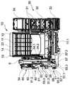
图1示出具有材料加工单元的材料加工装置10,所述材料加工单元当前以筛选单元的形式构成。筛选单元具有多个筛板11,所述筛板彼此上下设置在机器本体12中。在此,机器本体12形成筛选单元的筛壳体。筛板11在重力方向上彼此上下设置。FIG. 1 shows a
机器本体12具有两个彼此平行的侧壁13,所述侧壁借助后壁14彼此连接。振动驱动器15设置在机器本体12处。借助所述振动驱动器15可以使各个筛板11置于振动中。如从附图中可以识别:筛板11相对于图平面中的水平线从右向左下倾。筛板11具有不同的网孔宽。在此,最上方的筛板11形成最大的网孔宽。最上方的筛板11在运输方向上汇入投放区域11.1中。交付到上筛板11上的材料在所述筛板11处筛分。由于其尺寸而未穿过筛板11落下的材料部分被供给至投放区域11.1。投放区域11.1将材料传送至第一移交带11.2。所述第一移交带11.2接收来自投放区域11.1的材料并将其横向于投放区域11.1的传送方向传送给返回带30。The
返回带30具有两个侧向的纵向支柱31,所述纵向支柱在返回带30的传送方向上延伸。纵向支柱31是返回带30的承载结构的一部分。辊子32固定在所述承载结构处。循环回转的传送带(未示出)可以在辊子32处滚动。The
返回带30的漏斗34设置在第一移交带11.2下方。所述漏斗34防止:来自第一移交带11.2的材料会从返回带30侧向落下。The
始于在漏斗34的区域中形成的接收区域33的材料借助于传送带传送至投放端部35。材料加工单元、特别是破碎机组可以连接于投放端部35。材料在所述破碎装置中被接收并粉碎。破碎机组可以是颚式破碎机、旋转冲击式破碎机或其他岩石破碎机。The material starting from the receiving
如从图1中可识别:牵引元件36在投放端部35的区域中借助于固定件36.2固定在返回带30处。牵引元件36可以由例如绳索或链条形成。牵引元件36在其背离投放端部35的端部处承载另外的固定件36.1。借助所述固定件36.1,牵引元件36可以固定在未示出的机器构件处。以此方式,稳定返回带30。As can be seen from FIG. 1 , the
筛选单元在上筛板11下方还具有另一筛板11,所述另一筛板在根据图1的视图中不再可识别,因为所述另一筛板设置在机器本体12中。The screening unit also has a
设置在上筛板11下方的筛板具有如下筛孔宽,所述筛孔宽小于上筛板11的筛孔宽。由筛板11筛出的材料到达细粒带20。细粒带20具有循环回转的运输带,所述运输带在机器本体12下方具有其交付区域。筛出的材料落到所述交付区域上并且借助细粒带20运输至细粒带20的投放端部22。筛出的材料在投放端部22处离开材料加工装置10并且传送到散装物堆上或输送给另一加工装置。为了避免材料侧向地从细粒带20落下,可以设有覆盖件23,所述覆盖件随机器本体12后覆盖细粒带20。The sieve plate disposed below the
细粒带20具有承载结构21。细粒带20借助所述承载结构21与机器本体12连接。为了驱动循环回转的运输带,在投放端部22的区域中设有驱动器24。The fine-grain belt 20 has a load-bearing structure 21 . The granule belt 20 is connected to the
为了将由筛选单元和细粒带20构成的结构单元固定在材料加工单元处设有耦联件。借助所述耦联件可以将所述结构单元与材料加工单元旋紧。材料加工单元在此可包括上述破碎机组。Couplings are provided in order to fasten the structural unit consisting of the screening unit and the fine-grain belt 20 on the material processing unit. The structural unit and the material processing unit can be screwed together by means of the coupling element. The material processing unit may here comprise the aforementioned crushing unit.
如上所述,材料从上筛板11中筛出。所述材料落到位于其下方的筛板11上。未被位于其下方的筛板11筛出的材料部分由筛选单元传送到第二移交带16上。第二移交带16的传送方向在此横向于筛板11的传送方向。筛出的材料经由第二移交带16到达传送带40。The material is screened out of the
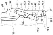
从图2中可以更详细地识别所述传送带40的结构。如图所示,传送带40可以具有与返回带30的结构基本相同的结构。The structure of the
相应地,使用两个在传送带40的纵向方向上伸展的支柱44.1。支柱44.1是承载结构的一部分。将用于循环回转的传送带44.3的辊子44.2固定在承载结构处。传送带44具有供应端的近端端部区域41。所述近端端部区域与筛选单元相关联。近端端部区域形成近端端部。在相对置的端部处,传送带40具有带有远端端部42的远端端部区域。Accordingly, two struts 44.1 extending in the longitudinal direction of the
近端端部区域41由基部部件43形成。与之相对,远端端部区域与其远端的端部42由传送带部件44形成。传送带40的中间区域形成在近端端部区域41和远端端部区域之间。传送带40的所述中间区域由传送带部件44形成。The
基部部件43经由枢转轴承45与传送带部件44耦联。传送带部件44可以借助于枢转轴承45相对于基部部件43枢转。在此,枢转轴线垂直于传送带44的传送方向伸展并且处于平行于根据图2的图平面的平面中。The
传送带40的基部部件43具有侧向设置的保持器52。稳固元件53可以固定在所述保持器52处。为此目的,稳固元件53具有轴承53.1,所述稳固元件可以借助于所述轴承能枢转地耦联到保持器52处。在相对置的端部处,稳固元件53具有另一轴承53.2。借助所述另一轴承53.2,稳固元件53能枢转地耦联到机器本体12处。The
例如,在此,可以得出如下关联:将竖直的承载件17固定在机器本体12处。为了相互加强,两个承载件17可以借助于横向支柱17.1相互连接。稳固元件53固定在承载件17之一处。借助稳固元件53,传送带40可以在图2中所示的工作位置中松弛。Here, for example, the following association can be derived: the
如图2还示出:设有调整机构50。调整机构50具有第一连杆51和第二连杆57。第一连杆51借助于第一铰链51.1能枢转地耦联到基部部件43处。第一连杆51的第二铰链51.2能枢转地耦联至机器本体12处,例如当前耦联至承载件17处。As also shown in FIG. 2 , an
第二连杆57在图1和2中以虚线示出。所述第二连杆借助第三铰链57.1能枢转地耦联到传送带40的基部部件43处。第四铰链57.2将第二连杆57与机器本体12连接。例如,第四铰链57.2在此可以设置在与机器本体12耦联的承载件17处。The
如从图2中可以识别:第三铰链57.1比第一铰链51.1更靠近传送带40的近端端部设置。As can be recognized from Figure 2: the third hinge 57.1 is arranged closer to the proximal end of the
从图2还可识别:第一连杆51具有从第一铰链51.1延伸到第二铰链51.2的第一杠杆长度。第二连杆57具有从第三铰链57.1延伸到第四铰链57.2的第二杠杆长度。在此,得出如下关联:第一杠杆长度大于第二杠杆。第一杠杆长度优选地至少是第二杠杆长度的两倍大。第二杠杆长度与第一杠杆长度的比特别优选地在1:2和1:3之间的范围内选择;该比优选地在1:2.3到1:2.7之间的范围内。It can also be recognized from Figure 2 that the
通过铰链51.1、51.2、57.1、57.2形成的铰链轴线彼此平行。以此方式,形成四铰链系统,近端端部区域41可围绕所述四铰链系统相对于机器本体12枢转。The hinge axes formed by the hinges 51.1, 51.2, 57.1, 57.2 are parallel to each other. In this way, a four hinge system is formed about which the
在本发明的范围内可以提出:第一连杆51和第二连杆57分别设置在传送带40的两侧。出于减少部件耗费的原因,连杆51、57优选结构相同地构成。Within the scope of the present invention it can be provided that the
连杆51、57的彼此相对置的铰链51.1、51.2、57.1、750.2具有彼此对齐的铰链轴线,使得获得四铰链系统。The mutually opposite hinges 51.1, 51.2, 57.1, 750.2 of the
图2还示出:第一连杆51具有耦联件51.3。力传递机构54以耦联点54.1固定在所述耦联件51.3处。力传递机构54是柔软的构件,例如绳索或链条。FIG. 2 also shows that the
力传递机构54经由偏转装置、例如偏转辊引导。偏转装置在横向支柱17.1的区域中固定在承载件17之一处。随偏转装置之后,力传递机构54具有第二耦联点54.2。所述耦联点54.2连接到执行机构55处。执行机构55具有可以以液压缸的形式构成的促动器55.2。The
液压缸具有在其中引导活塞的缸。活塞杆55.1连接到活塞处。活塞杆55.1连接到耦联点54.2处。促动器55.2具有耦联元件55.3。借助所述耦联元件,所述促动器连接到机器本体12处,优选地连接到承载件17处。The hydraulic cylinder has a cylinder in which the piston is guided. The piston rod 55.1 is attached to the piston. The piston rod 55.1 is connected to the coupling point 54.2. The actuator 55.2 has a coupling element 55.3. By means of the coupling element, the actuator is connected to the
在图2所示的位置中,传送带40处于形成基本位置的第一工作位置中。为了固定所述基本位置,传送带40具有止挡件58。所述止挡件58形状配合地支撑在机器本体12处的配合止挡件18.1处,使得远端端部42本身无法进一步下降。In the position shown in FIG. 2 , the
始于图2中所示的基本位置,传送带40可以相反于重力方向向上翻起、即相反于逆重力方向向上枢转。为此,首先移除稳固元件53,并且然后操作促动器55.2。然后,活塞杆55.1拉入缸中并且力传递机构54被拉动。以此方式,力传递机构54在耦联件51.3处提升第一连杆51。在此,调整机构执行图5和图6所示的枢转移动。Starting from the basic position shown in FIG. 2 , the
如从图5和图6中可以识别出:在枢转移动中,传送带40的近端端部从图5所示的基本位置向外从机器本体12下方朝侧向于机器本体12的方向引导,其中,所述近端端部由近端端部区域41的突出于第一铰链57.1的端部部段形成。在此,枢转移动为,使得将近端端部引导到弧形轨道上并且在此不下降或仅微小地下降。以此方式防止:传送带40的近端端部与位于其下方的区域、例如地面碰撞。As can be recognized from FIGS. 5 and 6 : in the pivoting movement, the proximal end of the
在图6中,传送带40处于向上翻起的运输位置。所述位置也在图3中示出。枢转移动借助止挡件58限制,所述止挡件58形状配合地抵靠机器本体侧的止挡件18.2。In Figure 6, the
当传送带40处于向上翻起的运输位置中时,传送带部分44可以围绕枢转轴承45相对于基部部件43下翻。在此,传送带部分44然后沿重力方下翻,直到其抵靠机器本体12侧向。以此方式,在运输位置中实现紧凑的构造。When the
传送带40可以不仅仅设置在图2所示的基本位置中。相反,传送带40的基部部件43也可以枢转到图2所示的基本位置和根据图3的向上翻起的位置之间的任何的中间位置中。为此,操作促动器55.2并且活塞杆55.1被拉入,直到达到传送带40的期望的枢转位置。例如,所述枢转位置可以借助稳固元件53来稳固,使得释放促动器55.2。为此目的,特别可以使用张紧设备53.3,借助所述张紧设备可以无级地设置可伸缩的稳固元件53在两个轴承53.1、53.2之间的长度。The
如图2、5和6所示,配合止挡件18.1和/或止挡件18.2可由支撑体56形成。例如,所述支撑体56可由耦联到机器本体12处的金属板坯形成。As shown in FIGS. 2 , 5 and 6 , the mating stop 18 . 1 and/or the stop 18 . 2 may be formed by the
在第一工作位置(根据图2)中,传送带40的负载的一部分可以经由支撑体56转移到机器本体12中。In the first working position (according to FIG. 2 ) part of the load of the
例如,止挡件18.2可用于:将传送带40安全地支撑在图6所示的运输位置中。For example, the stops 18.2 can be used to: support the
Claims (13)
Translated fromChineseApplications Claiming Priority (2)
| Application Number | Priority Date | Filing Date | Title |
|---|---|---|---|
| DE102020126743.6ADE102020126743A1 (en) | 2020-10-12 | 2020-10-12 | material processing facility |
| DE102020126743.6 | 2020-10-12 |
Publications (1)
| Publication Number | Publication Date |
|---|---|
| CN114313774Atrue CN114313774A (en) | 2022-04-12 |
Family
ID=78371759
Family Applications (1)
| Application Number | Title | Priority Date | Filing Date |
|---|---|---|---|
| CN202111187726.7APendingCN114313774A (en) | 2020-10-12 | 2021-10-12 | Material processing device |
Country Status (4)
| Country | Link |
|---|---|
| US (1) | US11896982B2 (en) |
| EP (1) | EP3988215A1 (en) |
| CN (1) | CN114313774A (en) |
| DE (1) | DE102020126743A1 (en) |
Cited By (1)
| Publication number | Priority date | Publication date | Assignee | Title |
|---|---|---|---|---|
| GB2630316A (en)* | 2023-05-23 | 2024-11-27 | Roco9 Ltd | Material processing apparatus with multi-mode conveyor |
Families Citing this family (1)
| Publication number | Priority date | Publication date | Assignee | Title |
|---|---|---|---|---|
| AT525972B1 (en)* | 2022-09-29 | 2023-10-15 | Sbm Mineral Proc Gmbh | PROCESSING DEVICE |
Citations (4)
| Publication number | Priority date | Publication date | Assignee | Title |
|---|---|---|---|---|
| US5819950A (en)* | 1996-04-05 | 1998-10-13 | Mccloskey; James Paschal | Portable trommel |
| CN105579144A (en)* | 2013-09-04 | 2016-05-11 | 美卓矿物公司 | Mineral material processing facility and method of operating a processing facility |
| US20160193610A1 (en)* | 2013-08-14 | 2016-07-07 | Sandvik Intelectual Property Ab | Mobile bulk material processing apparatus with slewing conveyor |
| CN111344071A (en)* | 2017-11-13 | 2020-06-26 | 山特维克知识产权股份有限公司 | Screening components and mobile material handlers |
Family Cites Families (12)
| Publication number | Priority date | Publication date | Assignee | Title |
|---|---|---|---|---|
| US4598875A (en)* | 1978-09-11 | 1986-07-08 | Allis-Chalmers Corporation | Portable crushing and screening plant |
| US4383651A (en)* | 1980-10-20 | 1983-05-17 | Allis-Chalmers Corporation | Portable crushing and screening plant |
| DE3837700C1 (en) | 1988-11-07 | 1990-04-12 | Franz 5503 Konz De Marx | Comminution apparatus arranged on a vehicle |
| DE9305837U1 (en) | 1993-04-20 | 1993-08-19 | Doppstadt, Werner, 42555 Velbert | Shredding machine |
| IT1280519B1 (en) | 1995-06-13 | 1998-01-22 | Seko Spa | MIXER-MIXER FOR THE RECOVERY OF GREEN RESIDUES WITH CONVEYOR BELT OF A PERFECT TYPE. |
| EP1655245A1 (en) | 2004-11-08 | 2006-05-10 | Johann Ruttnigg | Belt conveyor for a vehicle |
| GB2510839B (en)* | 2013-02-14 | 2017-11-01 | Terex Gb Ltd | Material Processing Apparatus with Multi-mode Feed Conveyor Assembly |
| DE102015104498B4 (en)* | 2015-03-25 | 2022-05-25 | Kleemann Gmbh | Folding mechanism for a conveyor |
| DE102016119856A1 (en)* | 2016-10-18 | 2018-04-19 | Kleemann Gmbh | Conveyor belt arrangement of a material processing device |
| CA3005521A1 (en)* | 2017-05-22 | 2018-11-22 | Vermeer Manufacturing Company | Pivoting conveyor |
| AU2018353113B2 (en)* | 2018-03-23 | 2023-12-21 | Metso Finland Oy | Movable material processing apparatus comprising a foldable conveyor |
| GB2585071B (en)* | 2019-06-27 | 2022-11-23 | Terex Gb Ltd | Material Processing Apparatus with Acess State Conveyor |
- 2020
- 2020-10-12DEDE102020126743.6Apatent/DE102020126743A1/enactivePending
- 2021
- 2021-10-01EPEP21200483.2Apatent/EP3988215A1/enactivePending
- 2021-10-11USUS17/498,293patent/US11896982B2/enactiveActive
- 2021-10-12CNCN202111187726.7Apatent/CN114313774A/enactivePending
Patent Citations (4)
| Publication number | Priority date | Publication date | Assignee | Title |
|---|---|---|---|---|
| US5819950A (en)* | 1996-04-05 | 1998-10-13 | Mccloskey; James Paschal | Portable trommel |
| US20160193610A1 (en)* | 2013-08-14 | 2016-07-07 | Sandvik Intelectual Property Ab | Mobile bulk material processing apparatus with slewing conveyor |
| CN105579144A (en)* | 2013-09-04 | 2016-05-11 | 美卓矿物公司 | Mineral material processing facility and method of operating a processing facility |
| CN111344071A (en)* | 2017-11-13 | 2020-06-26 | 山特维克知识产权股份有限公司 | Screening components and mobile material handlers |
Cited By (2)
| Publication number | Priority date | Publication date | Assignee | Title |
|---|---|---|---|---|
| GB2630316A (en)* | 2023-05-23 | 2024-11-27 | Roco9 Ltd | Material processing apparatus with multi-mode conveyor |
| GB2630316B (en)* | 2023-05-23 | 2025-06-25 | Roco9 Ltd | Material processing apparatus with multi-mode conveyor |
Also Published As
| Publication number | Publication date |
|---|---|
| US20220111396A1 (en) | 2022-04-14 |
| EP3988215A1 (en) | 2022-04-27 |
| US11896982B2 (en) | 2024-02-13 |
| DE102020126743A1 (en) | 2022-04-14 |
Similar Documents
| Publication | Publication Date | Title |
|---|---|---|
| CN111344071B (en) | Screen assembly and mobile material processor | |
| US9010542B2 (en) | Screen lift mechanism for variable slope vibrating screens | |
| CA2642612C (en) | A material screening apparatus | |
| CN112604939B (en) | Rock processing equipment | |
| EP3041613B1 (en) | A mineral material processing plant and a method for operating a processing plant | |
| CN105579144B (en) | Mineral material processing facility and method of operating a processing facility | |
| CN114313774A (en) | Material processing device | |
| JP6234587B2 (en) | Mineral material processing equipment and operating method of processing equipment | |
| CN104093501A (en) | Material Processing Equipment | |
| US6065606A (en) | Elevatable frame for transportable sorting machines | |
| CN114955379B (en) | Mobile machine for handling bulk materials with a component carrier movable on a conveying section | |
| US20240140719A1 (en) | Material processing device and method for adjusting a conveyor device of a material processing device | |
| JP2809598B2 (en) | Belt conveyor equipment for mobile conveyor processing equipment | |
| KR102856155B1 (en) | coal distributor for decreasing falling coal | |
| US12103041B2 (en) | Portable screening and stockpiling apparatus | |
| AU2012205216A1 (en) | A material screening apparatus | |
| RU2741925C1 (en) | Installation for processing mineral materials | |
| IES84870Y1 (en) | A material screening apparatus |
Legal Events
| Date | Code | Title | Description |
|---|---|---|---|
| PB01 | Publication | ||
| PB01 | Publication | ||
| SE01 | Entry into force of request for substantive examination | ||
| SE01 | Entry into force of request for substantive examination |