CN114310062A - A kind of scraper conveyor sprocket group damage repair device and method - Google Patents
A kind of scraper conveyor sprocket group damage repair device and methodDownload PDFInfo
- Publication number
- CN114310062A CN114310062ACN202210105236.6ACN202210105236ACN114310062ACN 114310062 ACN114310062 ACN 114310062ACN 202210105236 ACN202210105236 ACN 202210105236ACN 114310062 ACN114310062 ACN 114310062A
- Authority
- CN
- China
- Prior art keywords
- scraper conveyor
- damage
- chain wheel
- conveyor chain
- repair
- Prior art date
- Legal status (The legal status is an assumption and is not a legal conclusion. Google has not performed a legal analysis and makes no representation as to the accuracy of the status listed.)
- Granted
Links
- 230000008439repair processEffects0.000titleclaimsabstractdescription53
- 238000000034methodMethods0.000titleclaimsabstractdescription25
- 238000001514detection methodMethods0.000claimsabstractdescription31
- 238000004458analytical methodMethods0.000claimsabstractdescription6
- 238000003466weldingMethods0.000claimsdescription12
- 239000011159matrix materialSubstances0.000claimsdescription10
- 230000000712assemblyEffects0.000claimsdescription7
- 238000000429assemblyMethods0.000claimsdescription7
- 238000013519translationMethods0.000claimsdescription7
- 230000007246mechanismEffects0.000claimsdescription6
- 239000007787solidSubstances0.000claimsdescription6
- 230000005540biological transmissionEffects0.000claimsdescription4
- 230000008569processEffects0.000claimsdescription4
- 238000001914filtrationMethods0.000claimsdescription3
- 230000010354integrationEffects0.000claimsdescription3
- 230000009467reductionEffects0.000claimsdescription3
- 230000009466transformationEffects0.000description6
- 238000004445quantitative analysisMethods0.000description5
- 230000008859changeEffects0.000description4
- 239000003245coalSubstances0.000description4
- 238000012545processingMethods0.000description4
- 230000007547defectEffects0.000description3
- 238000005065miningMethods0.000description3
- 230000004807localizationEffects0.000description2
- 238000004519manufacturing processMethods0.000description2
- 238000012360testing methodMethods0.000description2
- 230000000007visual effectEffects0.000description2
- 230000009471actionEffects0.000description1
- 230000008901benefitEffects0.000description1
- 238000012937correctionMethods0.000description1
- 238000005520cutting processMethods0.000description1
- 125000004122cyclic groupChemical group0.000description1
- 238000013461designMethods0.000description1
- 230000000694effectsEffects0.000description1
- 238000000605extractionMethods0.000description1
- 230000006872improvementEffects0.000description1
- 238000007689inspectionMethods0.000description1
- 239000000463materialSubstances0.000description1
- 238000005259measurementMethods0.000description1
- 238000012986modificationMethods0.000description1
- 230000004048modificationEffects0.000description1
- 238000011002quantificationMethods0.000description1
Images

Landscapes
- Manipulator (AREA)
Abstract
Description
Translated fromChinese技术领域technical field
本发明涉及煤矿机械检测技术领域,特别是涉及一种刮板输送机链轮组损伤修复装置及方法。The invention relates to the technical field of coal mine machinery detection, in particular to a damage repairing device and method for a chain wheel set of a scraper conveyor.
背景技术Background technique
采煤工作面作为煤炭的第一生产现场,作业空间小、机械设备多、视觉环境差,刮板输送机作为三机配套设备中最主要的物料运输设备,复杂的自身结构和恶劣的工作环境决定了其显著的动力学特性,链轮组在采煤工作中长期承受冲击和循环载荷的交替作用,极易造成链轮组的严重损伤;链轮组的破坏将造成整个链传动系统的载荷突变,易导致卡链、脱链故障发生,使整个链传动运行系统短时间将承受巨大的冲击载荷,严重时会造成链条断裂和电机烧毁,直接影响了整个综采工作面的生产效率和人员设备安全。As the first production site of coal, the coal mining face has small working space, many mechanical equipment and poor visual environment. The scraper conveyor is the most important material transportation equipment among the three-machine supporting equipment, which has a complex structure and a harsh working environment. Determines its remarkable dynamic characteristics. The sprocket group bears the alternating action of impact and cyclic load for a long time in the coal mining work, which is very easy to cause serious damage to the sprocket group; the damage of the sprocket group will cause the load of the entire chain transmission system. The sudden change can easily lead to the occurrence of chain jam and off-chain failures, so that the entire chain drive operation system will bear huge impact loads in a short time, and in severe cases, the chain will be broken and the motor will be burned, which directly affects the production efficiency and personnel of the entire fully mechanized mining face. Equipment security.
现阶段对刮板输送机链轮损伤的检测主要是人工视觉分辨来完成的,损伤位置的修复处理也是人工操作。这种由人工视觉分辨去检测试件的缺陷的方法,受到人工的限制和外界环境的影响,不仅检测产品的速度慢、效率低下,而且在检测的过程中容易出错,更不能实现损伤的量化分析;此外,传统的人工修复方法以人的主观观察为依据,存在过多的不确定性,且人工修复的好坏受个人的操作熟练程度、对损伤的判定的影响严重,不易实现精准修复,无法保证修复后链轮组的可靠性和稳定性。因此,如何实现刮板输送机链轮的智能化损伤检测、并得到链轮组的损伤位置空间坐标、缺损量等信息,并依据这些信息实现链轮损伤位置的自动化、智能化修复是现阶段亟需解决的问题。At this stage, the detection of the damage of the scraper conveyor sprocket is mainly completed by artificial visual discrimination, and the repair of the damaged position is also manual operation. This method of detecting the defects of the test piece by artificial vision is limited by the artificial and the influence of the external environment. It is not only slow and inefficient to detect the product, but also prone to errors in the process of detection, and it cannot realize the quantification of damage. Analysis; in addition, the traditional manual repair method is based on human subjective observation, and there are too many uncertainties, and the quality of manual repair is seriously affected by the individual's operating proficiency and the judgment of damage, and it is not easy to achieve accurate repair. , the reliability and stability of the repaired sprocket set cannot be guaranteed. Therefore, how to realize the intelligent damage detection of the sprocket of the scraper conveyor, and obtain the information such as the spatial coordinates of the damage position and the defect amount of the sprocket group, and realize the automatic and intelligent repair of the damage position of the sprocket according to this information is the current stage. Urgent problem to be solved.
发明内容SUMMARY OF THE INVENTION
本发明的目的是提供一种刮板输送机链轮组损伤修复装置及方法,以解决上述现有技术存在的问题,能够实现刮板输送机链轮组损伤位置的自动化、智能化修复。The purpose of the present invention is to provide a scraper conveyor sprocket group damage repair device and method, so as to solve the problems existing in the above-mentioned prior art, and can realize automatic and intelligent repair of the damage position of the scraper conveyor sprocket group.
为实现上述目的,本发明提供了如下方案:本发明提供一种刮板输送机链轮组损伤修复方法,包括:In order to achieve the above purpose, the present invention provides the following solutions: the present invention provides a method for repairing damage to a scraper conveyor sprocket group, comprising:
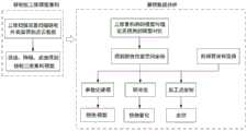
模型建立;通过三维扫描装置对刮板输送机链轮组进行重构,得到其实际结构的三维重构模型;Model establishment; reconstruct the chain wheel group of the scraper conveyor through the three-dimensional scanning device, and obtain the three-dimensional reconstruction model of its actual structure;
损伤定位;建立相应的刮板输送机链轮组无损伤结构的三维理想模型,进行对比,得到损伤数据;Damage localization; establish a three-dimensional ideal model of the damage-free structure of the corresponding scraper conveyor sprocket group, compare and obtain damage data;
定量检测;根据损伤数据计算出损伤量,进而实现损伤定量分析,并建立堆焊修复模型;Quantitative detection; calculate the damage amount according to the damage data, then realize the quantitative analysis of the damage, and establish the surfacing repair model;
损伤修复;将堆焊修复模型转化成通过检测修复装置可识别数据并对刮板输送机链轮组进行堆焊修复。Damage repair; convert the surfacing repair model into identifiable data through the detection and repair device and perform surfacing repair on the scraper conveyor sprocket group.
所述模型建立中通过三维扫描装置对所述刮板输送机链轮组做全方位扫描,得到所述刮板输送机链轮组的点云数据,将所述点云数据进行图像拼接最终得到所述三维重构模型。In the establishment of the model, the three-dimensional scanning device is used to scan the chain wheel set of the scraper conveyor in all directions, and the point cloud data of the chain wheel set of the scraper conveyor is obtained, and the image stitching of the point cloud data is finally obtained. the three-dimensional reconstruction model.
所述图像拼接是通过三维扫描装置得到的所述点云数据进行旋转平移,通过迭代算法寻找处两片点云的初始位置;记录旋转平移的角度和距离;之后对所述刮板输送机链轮进行扫描之后,加入算法,引入旋转平移的角度和距离,完成图像拼接。The image stitching is to rotate and translate the point cloud data obtained by the three-dimensional scanning device, and find the initial positions of the two point clouds through an iterative algorithm; record the angle and distance of the rotation and translation; After the wheel scans, an algorithm is added to introduce the angle and distance of the rotation and translation to complete the image stitching.
所述损伤量是将各个损伤处三重积分的方法计算出体积变化量。The damage amount is calculated by the method of triple integration of each damage site to calculate the volume change amount.
所述损伤定量分析将各个所述损伤处的的空间坐标用参数化建模的方法生成损伤实体模型,使用cad软件进行切片操作,用以构建内外轮廓环边界,并分析计算出截面的面积。In the damage quantitative analysis, the spatial coordinates of each damage site are generated by parametric modeling to generate a damage entity model, and cad software is used to perform a slicing operation to construct an inner and outer contour ring boundary, and analyze and calculate the area of the section.
在所述立堆焊修复模型上建立检测修复坐标系和修复件坐标系,计算所述检测修复装置与所述刮板输送机链轮组修复件之间的关系矩阵。A detection and repair coordinate system and a repair part coordinate system are established on the vertical surfacing repair model, and a relationship matrix between the detection and repair device and the repair part of the scraper conveyor sprocket assembly is calculated.
一种刮板输送机链轮组损伤修复装置,包括三维扫描装置和检测修复装置,所述检测修复装置包括支撑框体;所述支撑框体底部安装有行走机构;所述支撑框体顶面中部固定安装有旋转电机;所述旋转电机的输出轴竖直贯穿所述支撑框体顶面,且所述输出轴转动安装于所述支撑框体底部;所述输出轴上安装有刮板输送机链轮;所述支撑框体内侧壁还设置有机械臂组件;所述机械臂组件与所述刮板输送机链轮位置对应;A damage repairing device for a scraper conveyor sprocket group, comprising a three-dimensional scanning device and a detection and repairing device, the detection and repairing device comprises a support frame body; a walking mechanism is installed at the bottom of the support frame body; the top surface of the support frame body A rotary motor is fixedly installed in the middle; the output shaft of the rotary motor vertically penetrates the top surface of the support frame, and the output shaft is rotatably installed at the bottom of the support frame; a scraper is installed on the output shaft for conveying a machine sprocket; the inner side wall of the support frame is also provided with a mechanical arm assembly; the mechanical arm assembly corresponds to the position of the scraper conveyor sprocket;
所述三维扫描装置正对所述刮板输送机链轮设置;The three-dimensional scanning device is disposed facing the scraper conveyor sprocket;
所述三维扫描装置包括旋转云台,云台驱动电机,上位机,三维扫描仪和导轨组件;所述上位机一侧设置有所述导轨组件;所述导轨组件上滑动安装有所述旋转云台;所述旋转云台一侧传动连接有所述云台驱动电机;所述旋转云台上还安装有所述三维扫描仪;所述三维扫描仪正对所述刮板输送机链轮设置,用于对所述刮板输送机链轮做全方位扫描;所述三维扫描仪与所述上位机电性连接,用于将扫描所述刮板输送机链轮得到的点云数据、上传到上位机进行滤波、降噪、拼接处理,最终得到刮板输送机链轮的三维重构模型。The three-dimensional scanning device includes a rotating pan/tilt, a pan/tilt drive motor, a host computer, a three-dimensional scanner and a guide rail assembly; the guide rail assembly is provided on one side of the host computer; the rotating cloud is slidably installed on the guide rail assembly The 3D scanner is also installed on the rotating PTZ; the 3D scanner is set facing the sprocket of the scraper conveyor , which is used to scan the scraper conveyor sprocket in all directions; the 3D scanner is electrically connected to the upper computer, and is used to upload the point cloud data obtained by scanning the scraper conveyor sprocket to the The upper computer performs filtering, noise reduction, and splicing processing, and finally obtains the three-dimensional reconstruction model of the scraper conveyor sprocket.
所述导轨组件包括直线导轨;所述直线导轨竖直安装于所述上位机的一侧,所述直线导轨顶部固定安装有步进电机;所述步进电机与设置在所述直线导轨上的滑块传动连接;所述滑块上固定安装有所述旋转云台。The guide rail assembly includes a linear guide rail; the linear guide rail is vertically installed on one side of the upper computer, and a stepping motor is fixedly installed on the top of the linear guide rail; The sliding block is connected by transmission; the rotating head is fixedly installed on the sliding block.
所述机械臂组件对应设置有至少两组;所述机械臂组件对应设置于所述刮板输送机链轮上方和下方;At least two groups of the mechanical arm assemblies are correspondingly arranged; the mechanical arm assemblies are correspondingly arranged above and below the sprocket of the scraper conveyor;
所述机械臂组件包括基座,第一机械臂,第二机械臂和焊头;所述基座固定安装于所述支撑框体侧壁;所述第一机械臂与所述基座固定连接;所述第一机械臂活动端和第二机械臂末端通过万向节活动连接;所述焊头安装于所述第二机械臂前端;所述焊头朝向所述刮板输送机链轮设置。The robotic arm assembly includes a base, a first robotic arm, a second robotic arm and a welding head; the base is fixedly mounted on the side wall of the support frame; the first robotic arm is fixedly connected to the base ; The movable end of the first manipulator and the end of the second manipulator are movably connected by a universal joint; the welding head is mounted on the front end of the second manipulator; the welding head is arranged towards the scraper conveyor sprocket .
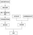
本发明公开了以下技术效果:本发明利用三维重构方法重构实际刮板输送机链轮组三维模型与理论无损伤三维模型,将实际三维模型与理论三维模型进行比对,获取损伤数据,在确定各个损伤处的空间坐标位置后,将各个损伤处用三重积分的方法计算出体积变化量,以此作为损伤量,实现链轮组损伤的定量化分析;The present invention discloses the following technical effects: the present invention utilizes a three-dimensional reconstruction method to reconstruct the three-dimensional model of the actual scraper conveyor sprocket set and the theoretical non-damage three-dimensional model, compares the actual three-dimensional model with the theoretical three-dimensional model, and obtains damage data, After determining the spatial coordinate position of each damage, calculate the volume change of each damage by triple integral method, and use this as the damage to realize the quantitative analysis of the damage of the sprocket group;
其次将各个损伤处的空间坐标位置用参数化建模的方法生成损伤实体模型,将其实缺损实体模型导入CAD软件进行切片操作,用以构建内外轮廓环边界,并利用CAD软件的分析功能计算出截面的面积,据此实现机械手堆焊路径规划,路径规划完成后,将生成的路径曲线串转换成机械臂组件可识别的机器代码;之后实现链轮组损伤位置的定位操作;最后控制器驱动检测修复装置实现堆焊任务,最终实现刮板输送机链轮组损伤位置的自动化、智能化修复。Secondly, the spatial coordinate position of each damage is used to generate the damage solid model by parametric modeling, and the actual defect solid model is imported into the CAD software for slicing operation to construct the inner and outer contour ring boundaries, and the analysis function of the CAD software is used to calculate the According to the area of the cross section, the manipulator surfacing path planning is realized. After the path planning is completed, the generated path curve string is converted into a machine code that can be recognized by the manipulator assembly; then the positioning operation of the damage position of the sprocket group is realized; finally, the controller drives the The detection and repair device realizes the surfacing task, and finally realizes the automatic and intelligent repair of the damaged position of the scraper conveyor sprocket group.
附图说明Description of drawings
为了更清楚地说明本发明实施例或现有技术中的技术方案,下面将对实施例中所需要使用的附图作简单地介绍,显而易见地,下面描述中的附图仅仅是本发明的一些实施例,对于本领域普通技术人员来讲,在不付出创造性劳动性的前提下,还可以根据这些附图获得其他的附图。In order to more clearly illustrate the embodiments of the present invention or the technical solutions in the prior art, the accompanying drawings required in the embodiments will be briefly introduced below. Obviously, the drawings in the following description are only some of the present invention. In the embodiments, for those of ordinary skill in the art, other drawings can also be obtained according to these drawings without creative labor.
图1为本发明的流程示意图;Fig. 1 is the schematic flow chart of the present invention;
图2为本发明的目标检测与修复流程图;Fig. 2 is the target detection and repair flow chart of the present invention;
图3为本发明的装置的轴测图;Figure 3 is an axonometric view of the device of the present invention;
图4为本发明装置的侧视图;4 is a side view of the device of the present invention;
其中,1、旋转电机;2、输出轴;3、刮板输送机链轮;4、旋转云台;5、云台驱动电机;6、上位机;7、机械臂基座;8、第一机械臂;9、万向节;10、第二机械臂;11、焊头;12、行走机构;13、步进电机;14、直线导轨;15、滑块;16、三维扫描仪;17、红外测距传感器。Among them, 1. Rotating motor; 2. Output shaft; 3. Scraper conveyor sprocket; 4. Rotating head; 5. Head driving motor; 6. Host computer; 7. Robot arm base; 8. First Robotic arm; 9. Universal joint; 10. Second robotic arm; 11. Welding head; 12. Walking mechanism; 13. Stepper motor; 14. Linear guide rail; 15. Slider; 16. Three-dimensional scanner; 17. Infrared ranging sensor.
具体实施方式Detailed ways
下面将结合本发明实施例中的附图,对本发明实施例中的技术方案进行清楚、完整地描述,显然,所描述的实施例仅仅是本发明一部分实施例,而不是全部的实施例。基于本发明中的实施例,本领域普通技术人员在没有做出创造性劳动前提下所获得的所有其他实施例,都属于本发明保护的范围。The technical solutions in the embodiments of the present invention will be clearly and completely described below with reference to the accompanying drawings in the embodiments of the present invention. Obviously, the described embodiments are only a part of the embodiments of the present invention, but not all of the embodiments. Based on the embodiments of the present invention, all other embodiments obtained by those of ordinary skill in the art without creative efforts shall fall within the protection scope of the present invention.
为使本发明的上述目的、特征和优点能够更加明显易懂,下面结合附图和具体实施方式对本发明作进一步详细的说明。In order to make the above objects, features and advantages of the present invention more clearly understood, the present invention will be described in further detail below with reference to the accompanying drawings and specific embodiments.
本发明提供一种刮板输送机链轮组损伤修复方法,包括:The invention provides a damage repair method for a scraper conveyor sprocket set, comprising:
模型建立;通过三维扫描装置对刮板输送机链轮组进行重构,得到其实际结构的三维重构模型;Model establishment; reconstruct the chain wheel group of the scraper conveyor through the three-dimensional scanning device, and obtain the three-dimensional reconstruction model of its actual structure;
损伤定位;建立相应的刮板输送机链轮组无损伤结构的三维理想模型,进行对比,得到损伤数据;Damage localization; establish a three-dimensional ideal model of the damage-free structure of the corresponding scraper conveyor sprocket group, compare and obtain damage data;
定量检测;根据损伤数据计算出损伤量,进而实现损伤定量分析,并建立堆焊修复模型;Quantitative detection; calculate the damage amount according to the damage data, then realize the quantitative analysis of the damage, and establish the surfacing repair model;
损伤修复;将堆焊修复模型转化成通过检测修复装置可识别数据并对刮板输送机链轮组进行堆焊修复。Damage repair; convert the surfacing repair model into identifiable data through the detection and repair device and perform surfacing repair on the scraper conveyor sprocket group.
模型建立中通过三维扫描装置对刮板输送机链轮组做全方位扫描,得到刮板输送机链轮组的点云数据,将点云数据进行图像拼接最终得到三维重构模型。In the model establishment, the three-dimensional scanning device is used to scan the chain wheel group of the scraper conveyor in all directions, and the point cloud data of the chain wheel group of the scraper conveyor is obtained.
图像拼接是通过三维扫描装置得到的点云数据进行旋转平移,通过迭代算法寻找处两片点云的初始位置;记录旋转平移的角度和距离;之后对刮板输送机链轮进行扫描之后,加入算法,引入旋转平移的角度和距离,完成图像拼接。Image stitching is to rotate and translate the point cloud data obtained by the 3D scanning device, and find the initial positions of the two point clouds through an iterative algorithm; record the angle and distance of the rotation and translation; then scan the scraper conveyor sprocket, add The algorithm introduces the angle and distance of rotation and translation to complete the image stitching.
损伤量是将各个损伤处三重积分的方法计算出体积变化量。The damage amount is the volume change amount calculated by triple integration of each damage.
损伤定量分析将各个损伤处的的空间坐标用参数化建模的方法生成损伤实体模型,使用cad软件进行切片操作,用以构建内外轮廓环边界,并分析计算出截面的面积。Quantitative analysis of damage: The spatial coordinates of each damage are used to generate a solid model of damage by parametric modeling, and cad software is used to perform slicing operations to construct the boundary of the inner and outer contour rings, and analyze and calculate the area of the section.
在立堆焊修复模型上建立检测修复坐标系和修复件坐标系,计算检测修复装置与刮板输送机链轮组修复件之间的关系矩阵;Establish the detection and repair coordinate system and the repaired part coordinate system on the vertical surfacing repair model, and calculate the relationship matrix between the inspection and repair device and the repaired parts of the scraper conveyor sprocket group;
预设检测修复装置末端与基座之间的变换矩阵为X,预设检测修复装置末端与修复件坐标系之间的位姿矩阵为Y,修复件的待加工点的位姿为Z,则可计算出检测修复装置的加工状态下末端装置位姿矩阵为:Q=X·Y·Z;通过三维软件将轮廓环曲线离散,把这些离散点的三维坐标值保存,通过机械臂路径规划算法求解运算求得检测修复装置每个关节的绝对转角,实现检测修复装置的控制修复。The preset transformation matrix between the end of the detection and repair device and the base is X, the preset pose matrix between the end of the detection and repair device and the coordinate system of the repair part is Y, and the pose of the point to be processed of the repair part is Z, then It can be calculated that the pose matrix of the end device in the processing state of the detection and repair device is: Q=X·Y·Z; the contour ring curve is discretized by 3D software, the 3D coordinate values of these discrete points are saved, and the path planning algorithm of the robot arm is used. The solution operation is used to obtain the absolute rotation angle of each joint of the detection and repair device, so as to realize the control and repair of the detection and repair device.
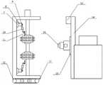
一种刮板输送机链轮组损伤修复装置,包括三维扫描装置和检测修复装置,检测修复装置包括支撑框体;支撑框体底部安装有行走机构;支撑框体顶面中部固定安装有旋转电机1;旋转电机1的输出轴2竖直贯穿支撑框体顶面,且输出轴2转动安装于支撑框体底部;输出轴2上安装有刮板输送机链轮3;支撑框体内侧壁还设置有机械臂组件;机械臂组件与刮板输送机链轮3位置对应;A damage repairing device for a scraper conveyor sprocket group, comprising a three-dimensional scanning device and a detection and repairing device, the detection and repairing device comprises a support frame body; a walking mechanism is installed at the bottom of the support frame body; a rotating motor is fixedly installed in the middle of the top surface of the
三维扫描装置正对刮板输送机链轮3设置;The three-dimensional scanning device is set directly on the
三维扫描装置包括旋转云台4,云台驱动电机5,上位机6,三维扫描仪16和导轨组件;上位机6一侧设置有导轨组件;导轨组件上滑动安装有旋转云台4;旋转云台4一侧传动连接有云台驱动电机5;旋转云台4上还安装有三维扫描仪16;三维扫描仪16正对刮板输送机链轮3设置,用于对刮板输送机链轮3做全方位扫描;三维扫描仪16与上位机6电性连接,用于将扫描刮板输送机链轮3得到的点云数据、上传到上位机进行滤波、降噪、拼接处理,最终得到刮板输送机链轮3的三维重构模型。The three-dimensional scanning device includes a rotating pan/
导轨组件包括直线导轨14;直线导轨14竖直安装于上位机6的一侧,直线导轨14顶部固定安装有步进电机13;步进电机13与设置在直线导轨14上的滑块15传动连接;滑块15上固定安装有旋转云台4。The guide rail assembly includes a
机械臂组件对应设置有至少两组;机械臂组件对应设置于刮板输送机链轮3上方和下方;There are at least two sets of mechanical arm assemblies correspondingly; the mechanical arm assemblies are correspondingly disposed above and below the
机械臂组件包括基座7,第一机械臂8,第二机械臂10和焊头11;基座7固定安装于支撑框体侧壁;第一机械臂8与基座固定连接;第一机械臂8活动端和第二机械臂10末端通过万向节9活动连接;焊头11安装于第二机械臂10前端;焊头11朝向刮板输送机链轮3设置。The robotic arm assembly includes a
在本发明的一个实施例中,如图3,机械臂组件设置有4组,上下各两组。In an embodiment of the present invention, as shown in FIG. 3 , there are four sets of robotic arm assemblies, two sets at the top and bottom.
在本发明的一个实施例中,行走机构采用四个麦克纳姆轮搭建底盘,因麦克纳姆轮的底盘能够进行四向移动,更易于在自主移动时控制支撑框体与三维扫描装置中心线偏差量的修正。In an embodiment of the present invention, the traveling mechanism uses four Mecanum wheels to build the chassis. Because the chassis of the Mecanum wheels can move in four directions, it is easier to control the support frame and the centerline of the three-dimensional scanning device when moving autonomously. Offset correction.
进一步的,还设置有对中检测组件,为高精度红外测距传感器17,其设置于支撑框体底面,且于支撑框体底面两侧各设置有两个,在更换试件过程中实时校准检支撑框体两侧与三维扫描装置间的距离,通过控制行走机构的移动使两边距离一致,即可保证支撑框体处于三维扫描装置中心线上,实现对中检测功能。Further, a centering detection component is also provided, which is a high-precision infrared ranging
在本发明的一个实施例中,所述刮板输送机链轮组三维重构模型与理论三维模型进行比对,得到损伤数据;进行对比的过程如下:首先,对两个三维模型进行特征提取得到特征点;此处定义链轮组的轮齿边线上的点作为特征点,然后通过进行相似性度量找到匹配的特征点对;通过匹配的特征点对得到三维模型的空间坐标变换参数;最后由坐标变换参数进行配准。In one embodiment of the present invention, the three-dimensional reconstruction model of the scraper conveyor sprocket group is compared with the theoretical three-dimensional model to obtain damage data; the process of comparing is as follows: first, feature extraction is performed on the two three-dimensional models Obtain the feature points; here define the points on the tooth sideline of the sprocket group as the feature points, and then find the matching feature point pair by performing similarity measurement; obtain the spatial coordinate transformation parameters of the three-dimensional model through the matching feature point pair; finally The registration is performed by coordinate transformation parameters.
在本发明的一个实施例中,损伤实体模型包含了模型的全部几何信息、记录了全部点、线、面、体的信息,导入三维软件后进行切片操作:首先得到损伤CAD实体模型与切平面的每条交线,将相连交线构成轮廓环,然后根据切平面轮廓环的存在规则,判断出内外轮廓环,最后构建内外轮廓环边界,并利用软件的分析功能计算出截面的面积。In one embodiment of the present invention, the damage solid model includes all the geometric information of the model, records all the information of points, lines, surfaces, and volumes, and is imported into the 3D software to perform a slicing operation: first, the damage CAD solid model and the cutting plane are obtained. For each intersecting line, the connected intersecting lines are formed into contour rings, and then according to the existence rules of the tangent plane contour rings, the inner and outer contour rings are judged, and finally the boundaries of the inner and outer contour rings are constructed, and the area of the section is calculated by the analysis function of the software.
在本发明的一个实施例中,机械臂组件的坐标变换过程如下坐标转换首先要建立基座坐标系和试件坐标系,计算检测试件与基座7之间的关系矩阵。设焊头11与基座之间的变换矩阵为X,若焊头11与工件坐标系之间的位姿矩阵为Y,待加工点的位姿为Z,则可计算出机械臂组件的加工状态下焊头11位姿矩阵为:Q=X·Y·Z;然后通过三维软件将轮廓环曲线离散,把这些离散点的三维坐标值保存,通过机械臂路径规划算法求解运算求得万向节9的绝对转角,实现机械臂组件的控制。In an embodiment of the present invention, the coordinate transformation process of the robotic arm assembly is as follows. The coordinate transformation first requires establishing the base coordinate system and the specimen coordinate system, and calculating the relationship matrix between the detection specimen and the
进一步的,其余机械臂组件做相同修复操作。Further, the rest of the robotic arm components are subjected to the same repair operation.
在本发明的描述中,需要理解的是,术语“纵向”、“横向”、“上”、“下”、“前”、“后”、“左”、“右”、“竖直”、“水平”、“顶”、“底”、“内”、“外”等指示的方位或位置关系为基于附图所示的方位或位置关系,仅是为了便于描述本发明,而不是指示或暗示所指的装置或元件必须具有特定的方位、以特定的方位构造和操作,因此不能理解为对本发明的限制。In the description of the present invention, it should be understood that the terms "portrait", "horizontal", "upper", "lower", "front", "rear", "left", "right", "vertical", The orientation or positional relationship indicated by "horizontal", "top", "bottom", "inner", "outer", etc. is based on the orientation or positional relationship shown in the drawings, and is only for the convenience of describing the present invention, rather than indicating or It is implied that the device or element referred to must have a particular orientation, be constructed and operate in a particular orientation, and therefore should not be construed as limiting the invention.
以上所述的实施例仅是对本发明的优选方式进行描述,并非对本发明的范围进行限定,在不脱离本发明设计精神的前提下,本领域普通技术人员对本发明的技术方案做出的各种变形和改进,均应落入本发明权利要求书确定的保护范围内。The above-mentioned embodiments are only to describe the preferred modes of the present invention, but not to limit the scope of the present invention. Without departing from the design spirit of the present invention, those of ordinary skill in the art can make various modifications to the technical solutions of the present invention. Variations and improvements should fall within the protection scope determined by the claims of the present invention.
Claims (10)
Priority Applications (1)
| Application Number | Priority Date | Filing Date | Title |
|---|---|---|---|
| CN202210105236.6ACN114310062B (en) | 2022-01-28 | 2022-01-28 | Device and method for repairing damage of chain wheel set of scraper conveyor |
Applications Claiming Priority (1)
| Application Number | Priority Date | Filing Date | Title |
|---|---|---|---|
| CN202210105236.6ACN114310062B (en) | 2022-01-28 | 2022-01-28 | Device and method for repairing damage of chain wheel set of scraper conveyor |
Publications (2)
| Publication Number | Publication Date |
|---|---|
| CN114310062Atrue CN114310062A (en) | 2022-04-12 |
| CN114310062B CN114310062B (en) | 2023-04-07 |
Family
ID=81031127
Family Applications (1)
| Application Number | Title | Priority Date | Filing Date |
|---|---|---|---|
| CN202210105236.6AActiveCN114310062B (en) | 2022-01-28 | 2022-01-28 | Device and method for repairing damage of chain wheel set of scraper conveyor |
Country Status (1)
| Country | Link |
|---|---|
| CN (1) | CN114310062B (en) |
Cited By (1)
| Publication number | Priority date | Publication date | Assignee | Title |
|---|---|---|---|---|
| CN118595679A (en)* | 2024-06-17 | 2024-09-06 | 无锡慧德自动化科技有限公司 | A surfacing welding control system |
Citations (8)
| Publication number | Priority date | Publication date | Assignee | Title |
|---|---|---|---|---|
| JPH09300071A (en)* | 1996-05-14 | 1997-11-25 | Matsumoto Kikai Kk | Automatic welding device for vertically welding butt-weld zone |
| CN105937692A (en)* | 2016-04-26 | 2016-09-14 | 上海颢汉数字技术有限公司 | Multifunctional three-dimensional shooting rack for three-dimensional reconstruction |
| CN206122951U (en)* | 2016-08-31 | 2017-04-26 | 辽宁恒耐科技有限公司 | Roller surfacing welding machine |
| CN109738891A (en)* | 2018-12-11 | 2019-05-10 | 北京金德创业测控技术有限公司 | A kind of various dimensions mechanical arm 3D radar level scanner |
| CN111549342A (en)* | 2020-06-12 | 2020-08-18 | 兰州理工大学白银新材料研究院 | Laser cladding repair method for double-row chain wheel |
| CN111702171A (en)* | 2020-05-28 | 2020-09-25 | 山东能源重装集团恒图科技有限公司 | 3D printing remanufacturing method for waste scraper conveyor chain wheel |
| CN112376045A (en)* | 2020-11-12 | 2021-02-19 | 中国科学院苏州生物医学工程技术研究所 | Three-dimensional repair method and system for irregular geometric shapes |
| CN213730121U (en)* | 2020-11-13 | 2021-07-20 | 南通理工学院 | Automatic change welding machines hand |
- 2022
- 2022-01-28CNCN202210105236.6Apatent/CN114310062B/enactiveActive
Patent Citations (8)
| Publication number | Priority date | Publication date | Assignee | Title |
|---|---|---|---|---|
| JPH09300071A (en)* | 1996-05-14 | 1997-11-25 | Matsumoto Kikai Kk | Automatic welding device for vertically welding butt-weld zone |
| CN105937692A (en)* | 2016-04-26 | 2016-09-14 | 上海颢汉数字技术有限公司 | Multifunctional three-dimensional shooting rack for three-dimensional reconstruction |
| CN206122951U (en)* | 2016-08-31 | 2017-04-26 | 辽宁恒耐科技有限公司 | Roller surfacing welding machine |
| CN109738891A (en)* | 2018-12-11 | 2019-05-10 | 北京金德创业测控技术有限公司 | A kind of various dimensions mechanical arm 3D radar level scanner |
| CN111702171A (en)* | 2020-05-28 | 2020-09-25 | 山东能源重装集团恒图科技有限公司 | 3D printing remanufacturing method for waste scraper conveyor chain wheel |
| CN111549342A (en)* | 2020-06-12 | 2020-08-18 | 兰州理工大学白银新材料研究院 | Laser cladding repair method for double-row chain wheel |
| CN112376045A (en)* | 2020-11-12 | 2021-02-19 | 中国科学院苏州生物医学工程技术研究所 | Three-dimensional repair method and system for irregular geometric shapes |
| CN213730121U (en)* | 2020-11-13 | 2021-07-20 | 南通理工学院 | Automatic change welding machines hand |
Cited By (1)
| Publication number | Priority date | Publication date | Assignee | Title |
|---|---|---|---|---|
| CN118595679A (en)* | 2024-06-17 | 2024-09-06 | 无锡慧德自动化科技有限公司 | A surfacing welding control system |
Also Published As
| Publication number | Publication date |
|---|---|
| CN114310062B (en) | 2023-04-07 |
Similar Documents
| Publication | Publication Date | Title |
|---|---|---|
| CN210155545U (en) | Be used for automatic on-line measuring equipment of switch manufacturing process | |
| CN106697326B (en) | Advanced automated process for wing-body engagement of an aircraft with predictive surface scanning | |
| CN104034263B (en) | A kind of non-contact measurement method of forging's block dimension | |
| CN110823704B (en) | TBM-carried rock slag online compressive strength testing system and method | |
| CN103307977B (en) | The field measurement apparatus of huge revolving class workpiece inner wall size, system and method | |
| TWI632342B (en) | Measuring equipment and measuring methods | |
| CN113146368B (en) | Steel rail surface quality detection system used on long trajectory | |
| CN110726726A (en) | Quantitative detection method and system for tunnel forming quality and defects thereof | |
| CN107289876A (en) | Multi-shaft interlocked vision, laser combined type non-contact measurement device for measuring and measuring method | |
| CN1987343A (en) | Intelligent holographic three dimension laser measuring system | |
| CN108489394A (en) | A kind of large-scale sheet metal works almost T-stable automatic detection device and method | |
| CN108278970A (en) | A kind of III type track plates machining deviation automated detection methods of CRTS | |
| CN110081821A (en) | Intelligent high-speed rail white body assembling quality detection device and its method | |
| CN114633262A (en) | Method for measuring welding allowance of ring weld of plate welding type parts and generating polishing track | |
| CN114310062B (en) | Device and method for repairing damage of chain wheel set of scraper conveyor | |
| TWI574003B (en) | Weld bead three-dimensional image detecting device and detecting method thereof | |
| CN1730248A (en) | A Reverse Engineering Robotic System | |
| CN113048882A (en) | Intelligent detection system for weld surface quality and implementation method | |
| CN113146432B (en) | An online grinding method for complex curved components | |
| CN108534707B (en) | large-scale scanning detection method for industrial manufacturing component | |
| CN107186701A (en) | A kind of teaching mechanical arm parameter calibration device and method of 3-freedom parallel mechanism | |
| CN108890649A (en) | A kind of teaching mechanical arm parameter calibration device and method of six-degree-of-freedom parallel connection mechanism | |
| CN216206091U (en) | Loader movable arm coaxiality detection device based on machine vision | |
| CN110394798A (en) | A kind of robot movement-control system angle sensor based and method | |
| CN113375598A (en) | Self-datum plane-based high-precision matching method for three-dimensional profile of blade |
Legal Events
| Date | Code | Title | Description |
|---|---|---|---|
| PB01 | Publication | ||
| PB01 | Publication | ||
| SE01 | Entry into force of request for substantive examination | ||
| SE01 | Entry into force of request for substantive examination | ||
| GR01 | Patent grant | ||
| GR01 | Patent grant | ||
| EE01 | Entry into force of recordation of patent licensing contract | Application publication date:20220412 Assignee:Guilin Zhongtian Machinery Co.,Ltd. Assignor:GUILIN University OF ELECTRONIC TECHNOLOGY Contract record no.:X2023980045855 Denomination of invention:A device and method for repairing damage to the sprocket group of a scraper conveyor Granted publication date:20230407 License type:Common License Record date:20231106 | |
| EE01 | Entry into force of recordation of patent licensing contract | ||
| OL01 | Intention to license declared | ||
| OL01 | Intention to license declared | ||
| EE01 | Entry into force of recordation of patent licensing contract | ||
| EE01 | Entry into force of recordation of patent licensing contract | Application publication date:20220412 Assignee:Guilin Teweian Technology Co.,Ltd. Assignor:GUILIN University OF ELECTRONIC TECHNOLOGY Contract record no.:X2024980028652 Denomination of invention:A device and method for repairing damage to the sprocket assembly of a scraper conveyor Granted publication date:20230407 License type:Common License Record date:20241129 | |
| EE01 | Entry into force of recordation of patent licensing contract | ||
| EE01 | Entry into force of recordation of patent licensing contract | Application publication date:20220412 Assignee:Guilin Yuanjing Electronic Technology Co.,Ltd. Assignor:GUILIN University OF ELECTRONIC TECHNOLOGY Contract record no.:X2025980002697 Denomination of invention:A device and method for repairing damage to the sprocket assembly of a scraper conveyor Granted publication date:20230407 License type:Open License Record date:20250121 |