CN114308835B - Instrument cleaning device for obstetrics and gynecology department - Google Patents
Instrument cleaning device for obstetrics and gynecology departmentDownload PDFInfo
- Publication number
- CN114308835B CN114308835BCN202210005879.3ACN202210005879ACN114308835BCN 114308835 BCN114308835 BCN 114308835BCN 202210005879 ACN202210005879 ACN 202210005879ACN 114308835 BCN114308835 BCN 114308835B
- Authority
- CN
- China
- Prior art keywords
- magnetic
- cleaning chamber
- assembly
- obstetrics
- wall
- Prior art date
- Legal status (The legal status is an assumption and is not a legal conclusion. Google has not performed a legal analysis and makes no representation as to the accuracy of the status listed.)
- Expired - Fee Related
Links
- 238000004140cleaningMethods0.000titleclaimsabstractdescription78
- 239000007921spraySubstances0.000claimsabstractdescription57
- 230000005540biological transmissionEffects0.000claimsabstractdescription22
- 230000000712assemblyEffects0.000claimsabstractdescription12
- 238000000429assemblyMethods0.000claimsabstractdescription12
- 238000000034methodMethods0.000claimsabstractdescription12
- 230000008569processEffects0.000claimsabstractdescription11
- 230000033001locomotionEffects0.000claimsdescription24
- 238000005192partitionMethods0.000claimsdescription17
- XLYOFNOQVPJJNP-UHFFFAOYSA-NwaterSubstancesOXLYOFNOQVPJJNP-UHFFFAOYSA-N0.000claimsdescription11
- 239000000463materialSubstances0.000claimsdescription10
- 238000002955isolationMethods0.000claimsdescription8
- 239000007788liquidSubstances0.000claimsdescription8
- 238000005406washingMethods0.000abstract1
- 230000001360synchronised effectEffects0.000description6
- 238000003745diagnosisMethods0.000description5
- 238000010586diagramMethods0.000description4
- 238000005507sprayingMethods0.000description4
- 238000011282treatmentMethods0.000description4
- 229910000990Ni alloyInorganic materials0.000description2
- VYPSYNLAJGMNEJ-UHFFFAOYSA-NSilicium dioxideChemical compoundO=[Si]=OVYPSYNLAJGMNEJ-UHFFFAOYSA-N0.000description2
- 230000009471actionEffects0.000description2
- 238000013459approachMethods0.000description2
- 201000010099diseaseDiseases0.000description2
- 208000037265diseases, disorders, signs and symptomsDiseases0.000description2
- 230000000694effectsEffects0.000description2
- 238000007689inspectionMethods0.000description2
- 230000005389magnetismEffects0.000description2
- 230000002265preventionEffects0.000description2
- 239000000741silica gelSubstances0.000description2
- 229910002027silica gelInorganic materials0.000description2
- 208000036818High risk pregnancyDiseases0.000description1
- 230000009286beneficial effectEffects0.000description1
- 230000035606childbirthEffects0.000description1
- 238000004891communicationMethods0.000description1
- 230000007423decreaseEffects0.000description1
- 238000001514detection methodMethods0.000description1
- 239000003814drugSubstances0.000description1
- 208000010515dystociaDiseases0.000description1
- 238000005265energy consumptionMethods0.000description1
- 230000003993interactionEffects0.000description1
- 210000000056organAnatomy0.000description1
- 231100000915pathological changeToxicity0.000description1
- 230000036285pathological changeEffects0.000description1
- 230000007170pathologyEffects0.000description1
- 230000035935pregnancyEffects0.000description1
- 230000001850reproductive effectEffects0.000description1
- 238000007789sealingMethods0.000description1
- 230000028327secretionEffects0.000description1
- 239000002699waste materialSubstances0.000description1
- 230000005186women's healthEffects0.000description1
Images


Landscapes
- Cleaning In General (AREA)
- Cleaning By Liquid Or Steam (AREA)
Abstract
Description
Translated fromChinese技术领域technical field
本发明涉及妇产科技术领域,具体涉及一种妇产科用仪器清洗装置。The invention relates to the technical field of obstetrics and gynecology, in particular to an instrument cleaning device for obstetrics and gynecology.
背景技术Background technique
妇产科是临床医学四大主要学科之一,主要研究女性生殖器官疾病的病因、病理、诊断和防治;妊娠、分娩的生理和病理变化;高危妊娠及难产的预防和诊治;女性生殖内分分泌及妇女保健等。在对妇产科患者进行疾病检测和诊治时,需要用到多种妇产科用仪器进行检查诊治,检查诊治结束后,需要对使用后的仪器进行清洗。Obstetrics and Gynecology is one of the four main disciplines of clinical medicine. It mainly studies the etiology, pathology, diagnosis and prevention of female reproductive organ diseases; the physiological and pathological changes of pregnancy and childbirth; the prevention, diagnosis and treatment of high-risk pregnancy and dystocia; Secretion and women's health care, etc. When performing disease detection, diagnosis and treatment on obstetrics and gynecology patients, it is necessary to use a variety of obstetrics and gynecology instruments for inspection, diagnosis and treatment. After the inspection, diagnosis and treatment, the used instruments need to be cleaned.
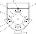
现有的妇产科用仪器清洗装置如图6所示,刷球f设置在弹力绳d上,振荡弹簧e套于弹力绳d外侧,拨动刷球f时,利用振荡弹簧e的形变,使得刷球f振荡,配合滚筒a旋转带动弧形座b上的刷头c旋转,能够对落入装置内的仪器进行清洗,拆卸密封盖g后可排出清洗废液。The existing obstetrics and gynecology instrument cleaning device is shown in Figure 6. The brush ball f is arranged on the elastic rope d, and the oscillating spring e is placed outside the elastic rope d. When the brush ball f is moved, the deformation of the oscillating spring e is used. Make the brush ball f oscillate, cooperate with the rotation of the roller a to drive the rotation of the brush head c on the arc-shaped seat b, and can clean the instrument falling into the device, and the cleaning waste liquid can be discharged after the sealing cover g is removed.
但是采用这种方式清洗妇产科用仪器时,仪器被清洗的角度有限,清洗件无法对仪器进行全方位的清洗,导致清洗效果较差。However, when cleaning obstetrics and gynecology instruments in this way, the angle at which the instruments are cleaned is limited, and the cleaning parts cannot clean the instruments in all directions, resulting in poor cleaning effect.
发明内容Contents of the invention
本发明的目的在于提供一种妇产科用仪器清洗装置,解决以下技术问题:The object of the present invention is to provide a kind of obstetrics and gynecology instrument cleaning device, solve the following technical problems:
妇产科用仪器被清洗的角度有限,清洗件无法对仪器进行全方位的清洗,导致清洗效果较差。Obstetrics and gynecology instruments are cleaned at a limited angle, and the cleaning parts cannot clean the instruments in all directions, resulting in poor cleaning effect.
本发明的目的可以通过以下技术方案实现:The purpose of the present invention can be achieved through the following technical solutions:
一种妇产科用仪器清洗装置,包括:A cleaning device for obstetrics and gynecology instruments, comprising:
清洗腔,其内设置有多个夹持组件;A cleaning chamber, in which a plurality of clamping components are arranged;
传动组件,用于带动多个夹持组件旋转,且旋转过程中多个夹持组件同方向上的投影不变;以及The transmission component is used to drive multiple clamping components to rotate, and the projections in the same direction of the multiple clamping components remain unchanged during the rotation process; and
第一喷头,两个所述第一喷头滑动安装于清洗腔内壁的一侧,且两个第一喷头由第一往复组件驱动同步进行相向运动或背向运动,所述第一往复组件与传动组件联动。The first spray head, the two first spray heads are slidably installed on one side of the inner wall of the cleaning chamber, and the two first spray heads are driven by the first reciprocating assembly to move towards each other or move backward synchronously, and the first reciprocating assembly and the transmission Component linkage.
作为本发明进一步的方案:所述装置还包括:As a further solution of the present invention: the device also includes:
第二喷头,两个所述第二喷头滑动安装于清洗腔内壁对应两个第一喷头相对的位置上,且第一往复组件与第二往复组件联动,以使两个第一喷头分别带动对应的两个第二喷头同步移动;以及The second nozzle, the two second nozzles are slidably installed on the inner wall of the cleaning chamber where the two first nozzles are opposite, and the first reciprocating assembly is linked with the second reciprocating assembly, so that the two first nozzles respectively drive the corresponding The two second nozzles move synchronously; and
第三喷头,两个所述第三喷头滑动安装于清洗腔内壁对应第一喷头与第二喷头之间的位置上,且第一往复组件以及第二往复组件均与第三往复组件联动,以使第一喷头与第二喷头分别带动相邻的两个第三喷头同步移动。The third spray head, the two third spray heads are slidably installed on the inner wall of the cleaning chamber at a position between the first spray head and the second spray head, and the first reciprocating assembly and the second reciprocating assembly are linked with the third reciprocating assembly to The first nozzle and the second nozzle respectively drive two adjacent third nozzles to move synchronously.
作为本发明进一步的方案:所述传动组件包括:As a further solution of the present invention: the transmission assembly includes:
转轴,转动安装于清洗腔内,并由驱动源驱动旋转;The rotating shaft is rotatably installed in the cleaning chamber and driven to rotate by the driving source;
滑轨,固定安装于清洗腔内,且其内滑动安装有多个活动柱,所述转轴与滑轨偏心布设;The slide rail is fixedly installed in the cleaning chamber, and a plurality of movable columns are slidably installed in it, and the rotating shaft and the slide rail are arranged eccentrically;
第一连杆,多个所述第一连杆的一端分别与多个活动柱转动连接,多个第一连杆的另一端分别与多个夹持组件固定连接;A first connecting rod, one end of the plurality of first connecting rods is respectively rotatably connected to a plurality of movable columns, and the other ends of the plurality of first connecting rods are respectively fixedly connected to a plurality of clamping assemblies;
第二连杆,多个所述第二连杆分别与多个第一连杆固定有夹持组件的端部转动连接,且第一连杆的此端贯穿第二连杆布设,多个所述第二连杆呈等圆周固定于转轴上;以及The second connecting rod, a plurality of the second connecting rods are respectively rotatably connected to the ends of the plurality of first connecting rods where the clamping assembly is fixed, and this end of the first connecting rod is arranged through the second connecting rod, and the plurality of the second connecting rods The second connecting rod is fixed on the rotating shaft in an equal circle; and
第三连杆,多个所述第三连杆的两端分别与两个夹持组件转动连接。As for the third connecting rod, both ends of the plurality of third connecting rods are respectively rotatably connected to the two clamping assemblies.
作为本发明进一步的方案:所述夹持组件包括:As a further solution of the present invention: the clamping assembly includes:
定位板,两个所述定位板分别与第一连杆以及第三连杆连接;A positioning plate, the two positioning plates are respectively connected with the first connecting rod and the third connecting rod;
组装杆,其两端分别与两个定位板连接;以及An assembly rod, the two ends of which are respectively connected with the two positioning plates; and
夹持块,相对布设的两个所述夹持块分别设置于两个定位板上。As for the clamping block, the two clamping blocks arranged oppositely are respectively arranged on two positioning plates.
作为本发明进一步的方案:所述组装杆为伸缩式结构。As a further solution of the present invention: the assembly rod is a telescopic structure.
作为本发明进一步的方案:所述第一往复组件包括:As a further solution of the present invention: the first reciprocating assembly includes:
第一滑环,设置于所述第一喷头上对应与清洗腔内壁的滑动连接处,且第一滑环具有磁性;The first slip ring is arranged on the first nozzle corresponding to the sliding connection with the inner wall of the cleaning chamber, and the first slip ring is magnetic;
磁性件,滑动安装于清洗腔外壁上,且两个磁性件与对应的两个第一滑环分别磁性相吸;The magnetic parts are slidably installed on the outer wall of the cleaning chamber, and the two magnetic parts are magnetically attracted to the corresponding two first slip rings;
连接轴,与转轴同轴固定连接,且其上对称布设有多个竖向的磁条,相邻两个所述磁条之间具有间隙,且磁条与磁性件磁性相吸;以及The connecting shaft is fixedly connected coaxially with the rotating shaft, and a plurality of vertical magnetic strips are symmetrically arranged on it, and there is a gap between two adjacent magnetic strips, and the magnetic strips and the magnetic parts are magnetically attracted; and
第一弹性件,其两端分别与磁性件以及清洗腔外壁连接,且第一弹性件连接于磁性件远离连接轴的端部。The two ends of the first elastic part are respectively connected with the magnetic part and the outer wall of the cleaning chamber, and the first elastic part is connected with the end of the magnetic part away from the connecting shaft.
作为本发明进一步的方案:所述第二往复组件包括:As a further solution of the present invention: the second reciprocating assembly includes:
第二滑环,设置于所述第二喷头上对应与清洗腔内壁的滑动连接处,所述第二滑环具有磁性,且两个第二滑环与对应的两个磁性件分别磁性相吸;以及The second slip ring is arranged on the second spray head corresponding to the sliding connection with the inner wall of the cleaning chamber, the second slip ring is magnetic, and the two second slip rings are magnetically attracted to the corresponding two magnetic parts respectively ;as well as
第一隔板,设置于所述清洗腔内壁对应两个第二滑环之间的位置上,且第一隔板由隔磁材料制成。The first partition is arranged on the inner wall of the cleaning chamber at a position corresponding to the position between the two second slip rings, and the first partition is made of a magnetic isolation material.
作为本发明进一步的方案:所述第三往复组件包括:As a further solution of the present invention: the third reciprocating assembly includes:
第三滑环,设置于所述第三喷头上对应与清洗腔内壁的滑动连接处,所述第三滑环具有磁性,且两个第三滑环与对应的两个磁性件分别磁性相斥;The third slip ring is arranged on the third spray head corresponding to the sliding connection with the inner wall of the cleaning chamber, the third slip ring is magnetic, and the two third slip rings and the corresponding two magnetic parts are magnetically repelled respectively ;
第二隔板,设置于所述清洗腔内壁对应两个第三滑环之间的位置上,且第二隔板由隔磁材料制成;以及The second partition is arranged on the inner wall of the cleaning chamber at a position corresponding to the position between the two third slip rings, and the second partition is made of a magnetic isolation material; and
第二弹性件,其两端分别与第三滑环以及第二隔板连接。The two ends of the second elastic member are respectively connected with the third slip ring and the second separator.
作为本发明进一步的方案:所述清洗腔外壁上设置有用于对第一弹性件以及第二弹性件导向的导向杆。As a further solution of the present invention: a guide rod for guiding the first elastic member and the second elastic member is provided on the outer wall of the cleaning chamber.
作为本发明进一步的方案:所述第一喷头、第二喷头以及第三喷头分别通过波纹管与蓄水箱连接,所述波纹管与蓄水箱的连接处设置有控制阀,且控制阀上并联有连接于蓄水箱的送液管以及连接于鼓风机的送风管。As a further solution of the present invention: the first nozzle, the second nozzle and the third nozzle are respectively connected to the water storage tank through bellows, and a control valve is arranged at the connection between the bellows and the water storage tank, and the control valve is A liquid supply pipe connected to the water storage tank and an air supply pipe connected to the blower are connected in parallel.
本发明的有益效果:Beneficial effects of the present invention:
(1)本发明中,通过传动组件带动多个夹持组件旋转,且旋转过程中多个夹持组件同方向上的投影不变,使得每个夹持组件移动至不同喷头的位置时,其上的仪器朝向喷头的角度面不同,传动组件能够带动第一往复组件驱动两个第一喷头同步进行相向运动或背向运动,使得第一喷头移动着对仪器进行喷洗,进而使得仪器能够得到全方位的清洗,有效避免了妇产科用仪器被清洗的角度有限,导致无法对仪器进行全方位的清洗的问题;(1) In the present invention, the transmission assembly drives multiple clamping components to rotate, and the projections of multiple clamping components in the same direction during the rotation process remain unchanged, so that when each clamping component moves to a different nozzle position, the The angles of the instruments facing the nozzles are different. The transmission component can drive the first reciprocating component to drive the two first nozzles to move towards each other or move backwards synchronously, so that the first nozzles move to spray and clean the instrument, so that the instrument can be completely Azimuth cleaning effectively avoids the problem that the obstetrics and gynecology instruments are cleaned at a limited angle, resulting in the inability to clean the instruments in all directions;
(2)本发明中,采用第一往复组件带动第二往复组件使得两个第一喷头分别带动对应的两个第二喷头同步移动,第一往复组件与第二往复组件配合可带动第三往复组件,使得第一喷头与第二喷头分别带动相邻的两个第三喷头同步移动,实现多个不同角度的喷头的移动,使得仪器能够得到全方位的清洗;(2) In the present invention, the first reciprocating assembly is used to drive the second reciprocating assembly so that the two first nozzles drive the corresponding two second nozzles to move synchronously, and the cooperation between the first reciprocating assembly and the second reciprocating assembly can drive the third reciprocating assembly. Assembly, so that the first nozzle and the second nozzle respectively drive the two adjacent third nozzles to move synchronously, realizing the movement of multiple nozzles with different angles, so that the instrument can be cleaned in all directions;
(3)本发明中,利用控制阀能够控制波纹管与送液管或是送风管连通,且波纹管仅会与其中一个管道连通,则喷头既可喷洒清水以清洗仪器,又可喷出热风以对清洗后的仪器进行干燥,提高了装置的实用性。(3) In the present invention, the control valve can be used to control the communication between the bellows and the liquid supply pipe or the air supply pipe, and the bellows will only communicate with one of the pipelines, then the nozzle can spray clean water to clean the instrument, and can spray out Hot air is used to dry the instrument after cleaning, which improves the practicability of the device.
附图说明Description of drawings
下面结合附图对本发明作进一步的说明。The present invention will be further described below in conjunction with the accompanying drawings.
图1是本发明整体结构示意图;Fig. 1 is a schematic diagram of the overall structure of the present invention;
图2是本发明中传动组件的结构示意图;Fig. 2 is the structural representation of transmission assembly among the present invention;
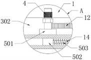
图3是本发明中图1的A处局部放大结构示意图;Fig. 3 is a schematic diagram of a partially enlarged structure at A of Fig. 1 in the present invention;
图4是本发明中第二往复组件的结构示意图;Fig. 4 is the structural representation of the second reciprocating assembly in the present invention;
图5是本发明中图1的B处局部放大结构示意图;Fig. 5 is a schematic diagram of a partially enlarged structure at B of Fig. 1 in the present invention;
图6是现有技术结构示意图。Fig. 6 is a schematic structural diagram of the prior art.
图中:1、清洗腔;2、夹持组件;201、定位板;202、组装杆;203、夹持块;3、传动组件;301、转轴;302、滑轨;303、活动柱;304、第一连杆;305、第二连杆;306、第三连杆;4、第一喷头;5、第一往复组件;501、第一滑环;502、磁性件;503、第一弹性件;504、连接轴;505、磁条;6、第二喷头;7、第二往复组件;701、第二滑环;702、第一隔板; 8、第三喷头;9、第三往复组件;901、第三滑环;902、第二弹性件;903、第二隔板;10、送液管;11、送风管;12、波纹管;13、控制阀;14、导向杆。In the figure: 1. Cleaning cavity; 2. Clamping component; 201. Positioning plate; 202. Assembly rod; 203. Clamping block; 3. Transmission component; 301. Rotating shaft; 302. Slide rail; 303. Movable column; 304 , the first connecting rod; 305, the second connecting rod; 306, the third connecting rod; 4, the first nozzle; 5, the first reciprocating assembly; 501, the first slip ring; 502, the magnetic part; 503, the first elastic 504, connecting shaft; 505, magnetic strip; 6, the second nozzle; 7, the second reciprocating assembly; 701, the second slip ring; 702, the first partition; 8, the third nozzle; 9, the third reciprocating Components; 901, the third slip ring; 902, the second elastic member; 903, the second partition; 10, the liquid delivery pipe; 11, the air supply pipe; 12, the bellows; 13, the control valve; 14, the guide rod.
具体实施方式detailed description
下面将结合本发明实施例中的附图,对本发明实施例中的技术方案进行清楚、完整地描述,显然,所描述的实施例仅仅是本发明一部分实施例,而不是全部的实施例。基于本发明中的实施例,本领域普通技术人员在没有作出创造性劳动前提下所获得的所有其它实施例,都属于本发明保护的范围。The following will clearly and completely describe the technical solutions in the embodiments of the present invention with reference to the accompanying drawings in the embodiments of the present invention. Obviously, the described embodiments are only some, not all, embodiments of the present invention. Based on the embodiments of the present invention, all other embodiments obtained by persons of ordinary skill in the art without creative efforts fall within the protection scope of the present invention.
请参阅图1-图4所示,本发明为一种妇产科用仪器清洗装置,包括:Please refer to Fig. 1-shown in Fig. 4, the present invention is a kind of obstetrics and gynecology instrument cleaning device, comprising:
清洗腔1,其内设置有多个夹持组件2;A
传动组件3,用于带动多个夹持组件2旋转,且旋转过程中多个夹持组件2同方向上的投影不变;以及The
第一喷头4,两个所述第一喷头4滑动安装于清洗腔1内壁的一侧,且两个第一喷头4由第一往复组件5驱动同步进行相向运动或背向运动,所述第一往复组件5与传动组件3联动;The
第二喷头6,两个所述第二喷头6滑动安装于清洗腔1内壁对应两个第一喷头4相对的位置上,且第一往复组件5与第二往复组件7联动,以使两个第一喷头4分别带动对应的两个第二喷头6同步移动;以及The
第三喷头8,两个所述第三喷头8滑动安装于清洗腔1内壁对应第一喷头4与第二喷头6之间的位置上,且第一往复组件5以及第二往复组件 7均与第三往复组件9联动,以使第一喷头4与第二喷头6分别带动相邻的两个第三喷头8同步移动。The
在本实施例的一种情况中,两个所述第一喷头4设置于清洗腔1的内底板上,两个所述第二喷头6设置于清洗腔1的内顶板上,每个所述清洗腔1的内侧板上均设置有两个第三喷头8。In one case of this embodiment, the two first spray heads 4 are arranged on the inner bottom plate of the
本实施例在实际应用时,多个夹持组件2上分别夹持多个妇产科用仪器,启动传动组件3带动多个夹持组件2旋转,且旋转过程中多个夹持组件2同方向上的投影不变,能够保证每个夹持组件2移动至不同喷头的位置时,其上的仪器朝向喷头的角度面不同,并且传动组件3带动多个夹持组件2旋转的同时,传动组件3能够带动第一往复组件5驱动两个第一喷头4同步进行往复直线运动,并且两个第一喷头4之间为同步的相向运动或背向运动,同时第一往复组件5带动第二往复组件7,使得两个第一喷头4分别带动对应的两个第二喷头6同步移动,第一往复组件5与第二往复组件7配合可带动第三往复组件9,使得第一喷头4与第二喷头6分别带动相邻的两个第三喷头8同步移动,也就是说,两个第一喷头4相向运动或背向运动时能够带动两个第二喷头6同步进行相向运动或背向运动,第一喷头4与第二喷头6移动能够分别带动相邻的第三喷头8移动,实现多个不同角度的喷头的移动,使得仪器能够得到全方位的清洗。In the actual application of this embodiment, a plurality of obstetrics and gynecology instruments are respectively clamped on a plurality of clamping
如图1-图3所示,作为本发明的一种优选实施例,所述传动组件3 包括:As shown in Figures 1-3, as a preferred embodiment of the present invention, the
转轴301,转动安装于清洗腔1内,并由驱动源驱动旋转;The
滑轨302,固定安装于清洗腔1内,且其内滑动安装有多个活动柱303,所述转轴301与滑轨302偏心布设;The
第一连杆304,多个所述第一连杆304的一端分别与多个活动柱303 转动连接,多个第一连杆304的另一端分别与多个夹持组件2固定连接;The first connecting
第二连杆305,多个所述第二连杆305分别与多个第一连杆304固定有夹持组件2的端部转动连接,且第一连杆304的此端贯穿第二连杆305 布设,多个所述第二连杆305呈等圆周固定于转轴301上;以及The second connecting
第三连杆306,多个所述第三连杆306的两端分别与两个夹持组件2 转动连接。The third
在本实施例的一种情况中,所述驱动源可以是电机组件,也可以是由电机带动的齿轮组件或者皮带轮组件,只要能够使得转轴301发生转动即可,本实施例在此不进行具体的限定。In one case of this embodiment, the driving source may be a motor assembly, or a gear assembly or a pulley assembly driven by a motor, as long as it can make the
当然,除上述结构外,所述传动组件3还可以选用两个旋转电机分别驱动夹持组件2绕清洗腔1旋转的同时发生自身旋转,以实现夹持组件2 夹持的仪器在旋转过程中位于同方向上的投影不变,在此不做限定。Of course, in addition to the above-mentioned structure, the
本实施例在实际应用时,驱动源驱动转轴301旋转,带动多个第二连杆305旋转,使得多个第一连杆304旋转,由于第一连杆304端部的活动柱303被滑轨302限位,而转轴301与滑轨302偏心布设,所以第一连杆 304被带动旋转时,其与第二连杆305之间发生相对旋转,并且第一连杆 304不会发生自转,也就是说,多个第一连杆304旋转过程中的朝向均相同,使得多个夹持组件2被带动旋转时,多个夹持组件2同方向上的投影不变,进而使得仪器转至不同的喷头时,仪器朝向喷头的角度面不同,使得仪器得到全方位式的清洗。In the actual application of this embodiment, the driving source drives the
如图1-图2所示,作为本发明的一种优选实施例,所述夹持组件2 包括:As shown in Figures 1-2, as a preferred embodiment of the present invention, the clamping
定位板201,两个所述定位板201分别与第一连杆304以及第三连杆 306连接;
组装杆202,其两端分别与两个定位板201连接;以及Assembling
夹持块203,相对布设的两个所述夹持块203分别设置于两个定位板 201上。Clamping
在本实施例的一种情况中,所述组装杆202为伸缩式结构;所述的缩式结构为多级管件嵌套而成的结构,实际应用时也可以采用齿轮齿条、电动伸缩杆的结构,本实施例在此不进行具体的限定。In one case of this embodiment, the
当然,除上述结构外,所述夹持组件2还可以选用液压缸带动两个夹持板移动以夹持仪器,在此不做限定。Of course, in addition to the above structure, the clamping
本实施例在实际应用时,将仪器放置在两个相对布设的夹持块203之间,两个夹持块203即可夹持仪器;调整组装杆202的长度即可调整两个定位板201之间的间距,进而调整两个夹持块203之间的间距,实现了对不同尺寸的仪器的夹持,提高了装置的实用性。In the actual application of this embodiment, the instrument is placed between two oppositely arranged clamping
如图1-图3所示,作为本发明的一种优选实施例,所述第一往复组件5包括:As shown in Figures 1-3, as a preferred embodiment of the present invention, the
第一滑环501,设置于所述第一喷头4上对应与清洗腔1内壁的滑动连接处,且第一滑环501具有磁性;The
磁性件502,滑动安装于清洗腔1外壁上,且两个磁性件502与对应的两个第一滑环501分别磁性相吸;The
连接轴504,与转轴301同轴固定连接,且其上对称布设有多个竖向的磁条505,相邻两个所述磁条505之间具有间隙,且磁条505与磁性件 502磁性相吸;以及The connecting
第一弹性件503,其两端分别与磁性件502以及清洗腔1外壁连接,且第一弹性件503连接于磁性件502远离连接轴504的端部。Both ends of the first
在本实施例的一种情况中,所述磁性件502可以选用永磁铁,也可以选用与电磁模块连接的电磁铁,本实施例在此不进行具体的限定;所述第一弹性件503可以选用如图3所示的弹簧,还可以选用其他具有弹性的部件替换,如硅胶柱,弹片等,在此不做具体的限定。In one case of this embodiment, the
除上述结构外,所述第一往复组件5还可以选用液压缸直接驱动两个第一喷头4移动,但是此方式下装置的能耗增加,本实施例中仪器旋转的过程中第一喷头4会被带动移动,提高了装置的自动化程度。In addition to the above structure, the
本实施例在实际应用时,转轴301旋转时能够带动连接轴504同步旋转,则多个磁条505旋转,当磁条505与磁性件502之间的横向间距最小时,二者之间的磁吸力最大,磁性件502向磁条505的方向移动,则第一弹性件503拉伸,随后磁条505转离,其与磁性件502之间的横向间距增大时,则二者之间的磁吸力减小,此时第一弹性件503恢复形变的弹力使得磁性件502向初始位置移动,如此往复即可实现第一弹性件503的往复直线运动,由于多个竖向的磁条505对称布设,所以位于连接轴504两侧的两个磁性件502能够进行同步的相向运动或背向运动,进而实现两个第一滑环501的同步相向运动或背向运动,使得两个第一喷头4进行同步的相向运动或背向运动,能够有效扩大对旋转的仪器清洗范围。When this embodiment is used in practice, when the
如图1-图4所示,作为本发明的一种优选实施例,所述第二往复组件7包括:As shown in Figures 1-4, as a preferred embodiment of the present invention, the
第二滑环701,设置于所述第二喷头6上对应与清洗腔1内壁的滑动连接处,所述第二滑环701具有磁性,且两个第二滑环701与对应的两个磁性件502分别磁性相吸;以及The
第一隔板702,设置于所述清洗腔1内壁对应两个第二滑环701之间的位置上,且第一隔板702由隔磁材料制成。The
在本实施例的一种情况中,所述隔磁材料可以选用镍合金,还可以选用其他高磁化率材料,本实施例在此不进行列举。In one case of this embodiment, the magnetic isolation material may be nickel alloy, or other high magnetic susceptibility materials, which are not listed here in this embodiment.
除上述结构外,所述第二往复组件7还可以选用液压缸直接驱动两个第二喷头6移动,在此不做限定。In addition to the above structure, the
本实施例在实际应用时,磁性件502进行往复移动的过程中,磁吸力作用下两个磁性件502移动时会分别带动两个第二滑环701同步移动,进而实现两个第二滑环701的同步相向运动或背向运动,使得两个第二喷头 6能够进行同步的相向运动或背向运动,即两个第一喷头4移动会带动两个第二喷头6同步移动,能够增大对仪器的喷洗面积;第一隔板702的设置能够避免两个第二滑环701之间的磁性相互影响。In the actual application of this embodiment, during the reciprocating movement of the
如图1-图4所示,作为本发明的一种优选实施例,所述第三往复组件9包括:As shown in Figures 1-4, as a preferred embodiment of the present invention, the
第三滑环901,设置于所述第三喷头8上对应与清洗腔1内壁的滑动连接处,所述第三滑环901具有磁性,且两个第三滑环901与对应的两个磁性件502分别磁性相斥;The
第二隔板903,设置于所述清洗腔1内壁对应两个第三滑环901之间的位置上,且第二隔板903由隔磁材料制成;以及The
第二弹性件902,其两端分别与第三滑环901以及第二隔板903连接。Two ends of the second
在本实施例的一种情况中,所述隔磁材料可以选用镍合金,还可以选用其他高磁化率材料,本实施例在此不进行列举;所述第二弹性件902可以选用如图1所示的弹簧,还可以选用其他具有弹性的部件替换,如硅胶柱,弹片等,在此不做具体的限定。In one case of this embodiment, the magnetic isolation material can be nickel alloy, or other high magnetic susceptibility materials, which are not listed in this embodiment; the second
当然,除上述结构外,所述第三往复组件9还可以选用连接板将第三喷头8与第一喷头4以及第二喷头6分别转动连接,本实施例在此不进行限定。Of course, in addition to the above structure, the
本实施例在实际应用时,两个第一喷头4进行同步的相向运动或背向运动会带动两个第二喷头6同样进行同步的相向运动或背向运动,当磁性件502靠近与其相邻的第三滑环901时,与此磁性件502对应的第二滑环 701靠近与其相邻的第三滑环901,磁斥力作用下,此两个第三滑环901 分别向远离此磁性件502以及此第二滑环701的方向移动,则两个第三滑环901相向运动,带动了两个第三喷头8相互靠近,第二弹性件902被压缩,随后此磁性件502以及此第二滑环701向初始位置移动,即分别远离两个第三滑环901,则两个第三滑环901在第二弹性件902恢复形变的弹力下向初始位置移动,即两个第三滑环901背向运动,如此往复,可实现磁性件502移动时配合与其对应的第二滑环701能够带动两个第三滑环901进行相向运动或背向运动,进而实现了两个第三喷头8的相向运动或背向运动,即多个喷头均会移动着喷洗仪器,有效提高了喷洗面积;第二隔板903的设置能够避免两个第三滑环901之间的磁性影响。In the actual application of this embodiment, the synchronous movement of the two
如图1-图3所示,作为本发明的一种优选实施例,所述清洗腔1外壁上设置有用于对第一弹性件503以及第二弹性件902导向的导向杆14。As shown in FIGS. 1-3 , as a preferred embodiment of the present invention, a
在本实施例的一种情况中,所述导向杆14可以选用如图3所示的伸缩式结构,还可以选用限位块的部件替代,在此不做限定;所述的伸缩式结构为多级管件嵌套而成的结构,实际应用时也可以采用齿轮齿条、电动伸缩杆的结构,本实施例在此不进行具体的限定。In one case of this embodiment, the
本实施例在实际应用时,导向杆14的设置能够有效避免第一弹性件 503以及第二弹性件902发生形变时偏移预设路径的问题,提高了装置运行时的稳定性。In practical application of this embodiment, the setting of the
如图1-图5所示,作为本发明的一种优选实施例,所述第一喷头4、第二喷头6以及第三喷头8分别通过波纹管12与蓄水箱连接,所述波纹管12与蓄水箱的连接处设置有控制阀13,且控制阀13上并联有连接于蓄水箱的送液管10以及连接于鼓风机的送风管11。As shown in Figures 1-5, as a preferred embodiment of the present invention, the
在本实施例的一种情况中,所述控制阀13能够控制波纹管12与送液管10或是送风管11连通,且波纹管12仅会与其中一个管道连通;所述的控制阀13为现有技术,本申请未对其进行改进,因此,不需要公开其具体的机械结构以及电路结构,并不影响本申请的完整性。In one case of this embodiment, the
本实施例在实际应用时,清洗仪器的过程中,通过控制阀13控制波纹管12与送液管10连通,喷头即可喷洒清水;清洗完成后,通过控制阀 13控制波纹管12与送风管11连通,喷头即可喷出热风,能够对清洗后的仪器进行干燥,提高了装置的实用性。In practical application of this embodiment, in the process of cleaning the instrument, the
本发明的工作原理:本发明上述实施例中提供了一种妇产科用仪器清洗装置,通过传动组件3带动多个夹持组件2旋转,且旋转过程中多个夹持组件2同方向上的投影不变,使得每个夹持组件2移动至不同喷头的位置时,其上的仪器朝向喷头的角度面不同,传动组件3能够带动第一往复组件5驱动两个第一喷头4同步进行相向运动或背向运动,使得第一喷头 4移动着对仪器进行喷洗,进而使得仪器能够得到全方位的清洗,有效避免了妇产科用仪器被清洗的角度有限,导致无法对仪器进行全方位的清洗的问题。The working principle of the present invention: in the above-mentioned embodiment of the present invention, a cleaning device for obstetrics and gynecology instruments is provided. The
以上对本发明的一个实施例进行了详细说明,但所述内容仅为本发明的较佳实施例,不能被认为用于限定本发明的实施范围。凡依本发明申请范围所作的均等变化与改进等,均应仍归属于本发明的专利涵盖范围之内。An embodiment of the present invention has been described in detail above, but the content described is only a preferred embodiment of the present invention, and cannot be considered as limiting the implementation scope of the present invention. All equivalent changes and improvements made according to the application scope of the present invention shall still belong to the scope covered by the patent of the present invention.
Claims (8)
Translated fromChinesePriority Applications (1)
| Application Number | Priority Date | Filing Date | Title |
|---|---|---|---|
| CN202210005879.3ACN114308835B (en) | 2022-01-05 | 2022-01-05 | Instrument cleaning device for obstetrics and gynecology department |
Applications Claiming Priority (1)
| Application Number | Priority Date | Filing Date | Title |
|---|---|---|---|
| CN202210005879.3ACN114308835B (en) | 2022-01-05 | 2022-01-05 | Instrument cleaning device for obstetrics and gynecology department |
Publications (2)
| Publication Number | Publication Date |
|---|---|
| CN114308835A CN114308835A (en) | 2022-04-12 |
| CN114308835Btrue CN114308835B (en) | 2022-12-16 |
Family
ID=81024058
Family Applications (1)
| Application Number | Title | Priority Date | Filing Date |
|---|---|---|---|
| CN202210005879.3AExpired - Fee RelatedCN114308835B (en) | 2022-01-05 | 2022-01-05 | Instrument cleaning device for obstetrics and gynecology department |
Country Status (1)
| Country | Link |
|---|---|
| CN (1) | CN114308835B (en) |
Citations (19)
| Publication number | Priority date | Publication date | Assignee | Title |
|---|---|---|---|---|
| US5749385A (en)* | 1996-11-26 | 1998-05-12 | Steris Corporation | Method and apparatus for loosely retaining instruments in a washing system rack assembly |
| US6013227A (en)* | 1997-12-17 | 2000-01-11 | Johnson & Johnson Medical, Inc. | Lumen device reprocessor without occlusion |
| US6015529A (en)* | 1997-12-17 | 2000-01-18 | Johnson & Johnson Medical, Inc. | Tray/container system for cleaning/sterilization processes |
| WO2002017355A2 (en)* | 2000-07-07 | 2002-02-28 | Semitool, Inc. | Semiconductor wafer container cleaning apparatus |
| CN108553655A (en)* | 2018-04-16 | 2018-09-21 | 丁赛赛 | A kind of medical surgical knife disinfection system |
| CN208695735U (en)* | 2018-05-21 | 2019-04-05 | 平湖市瑞阳精密机械有限公司 | A kind of automatic washing machine of medical instrument |
| CN111085492A (en)* | 2019-12-31 | 2020-05-01 | 詹碧容 | Multifunctional medical instrument cleaning device |
| CN211186069U (en)* | 2019-11-20 | 2020-08-07 | 温州市瑞星鞋业有限公司 | Efficient belt cleaning device for shoes manufacturing |
| CN111618006A (en)* | 2020-05-22 | 2020-09-04 | 范梅芳 | Cleaning device for mechanical parts |
| CN211757084U (en)* | 2019-11-15 | 2020-10-27 | 郑皓 | Medical instrument belt cleaning device |
| CN112221094A (en)* | 2020-09-24 | 2021-01-15 | 王娟娟 | Automatic change ball cleaning equipment |
| CN212550719U (en)* | 2020-05-25 | 2021-02-19 | 贾立娟 | Cleaning, disinfecting and drying integrated equipment for medical basket for infectious ward |
| CN112495908A (en)* | 2020-12-01 | 2021-03-16 | 湖南康琪壹佰生物科技有限公司 | Throat-moistening candy production is with sugar grain mould cleaning device |
| CN213033117U (en)* | 2020-08-19 | 2021-04-23 | 苏州雪鹿超声波设备有限公司 | Material spraying and cleaning equipment for industrial processing |
| CN112691202A (en)* | 2020-12-30 | 2021-04-23 | 温州联豪化妆品有限公司 | High-temperature disinfection device for rotary medical instrument and use method thereof |
| CN213915118U (en)* | 2020-11-18 | 2021-08-10 | 牛璐 | Triangular cleaning rack for disinfection supply center |
| CN214022230U (en)* | 2020-11-12 | 2021-08-24 | 大连恒昌机电有限公司 | Spray set is used in automobile parts processing |
| CN214235288U (en)* | 2021-01-18 | 2021-09-21 | 常州市金坛区人民医院 | A kind of anti-infection supply room disinfection and sterilization nursing device |
| CN214865950U (en)* | 2021-02-05 | 2021-11-26 | 广州拾壹心智能装备有限责任公司 | Inner and outer wall cleaning and drying integrated device for garbage can |
Family Cites Families (7)
| Publication number | Priority date | Publication date | Assignee | Title |
|---|---|---|---|---|
| DK401789D0 (en)* | 1989-08-16 | 1989-08-16 | O & J Hojtryk As | CLEANING PROCEDURES |
| DE102012220646B3 (en)* | 2012-11-13 | 2014-03-13 | Meiko Maschinenbau Gmbh & Co. Kg | 3Hanging assortment and cleaning device for cleaning breathing apparatus |
| US10383353B2 (en)* | 2013-04-25 | 2019-08-20 | Weiwen Zhang | Vegetables washing method capable of splitting and separating impurities, and machine for implementing the same |
| DE102018118067A1 (en)* | 2018-07-26 | 2020-01-30 | Ecoclean Gmbh | cleaning device |
| CN111167792B (en)* | 2020-01-10 | 2021-03-16 | 淮阴工学院 | Automatic cleaning device for Bernoulli experimental equipment |
| CN111389812B (en)* | 2020-04-01 | 2021-05-07 | 常州市金坛区人民医院 | A medical device cleaning device |
| CN111483078A (en)* | 2020-04-16 | 2020-08-04 | 王守 | Cleaning equipment used before recovery processing of waste automobile tires |
- 2022
- 2022-01-05CNCN202210005879.3Apatent/CN114308835B/ennot_activeExpired - Fee Related
Patent Citations (19)
| Publication number | Priority date | Publication date | Assignee | Title |
|---|---|---|---|---|
| US5749385A (en)* | 1996-11-26 | 1998-05-12 | Steris Corporation | Method and apparatus for loosely retaining instruments in a washing system rack assembly |
| US6013227A (en)* | 1997-12-17 | 2000-01-11 | Johnson & Johnson Medical, Inc. | Lumen device reprocessor without occlusion |
| US6015529A (en)* | 1997-12-17 | 2000-01-18 | Johnson & Johnson Medical, Inc. | Tray/container system for cleaning/sterilization processes |
| WO2002017355A2 (en)* | 2000-07-07 | 2002-02-28 | Semitool, Inc. | Semiconductor wafer container cleaning apparatus |
| CN108553655A (en)* | 2018-04-16 | 2018-09-21 | 丁赛赛 | A kind of medical surgical knife disinfection system |
| CN208695735U (en)* | 2018-05-21 | 2019-04-05 | 平湖市瑞阳精密机械有限公司 | A kind of automatic washing machine of medical instrument |
| CN211757084U (en)* | 2019-11-15 | 2020-10-27 | 郑皓 | Medical instrument belt cleaning device |
| CN211186069U (en)* | 2019-11-20 | 2020-08-07 | 温州市瑞星鞋业有限公司 | Efficient belt cleaning device for shoes manufacturing |
| CN111085492A (en)* | 2019-12-31 | 2020-05-01 | 詹碧容 | Multifunctional medical instrument cleaning device |
| CN111618006A (en)* | 2020-05-22 | 2020-09-04 | 范梅芳 | Cleaning device for mechanical parts |
| CN212550719U (en)* | 2020-05-25 | 2021-02-19 | 贾立娟 | Cleaning, disinfecting and drying integrated equipment for medical basket for infectious ward |
| CN213033117U (en)* | 2020-08-19 | 2021-04-23 | 苏州雪鹿超声波设备有限公司 | Material spraying and cleaning equipment for industrial processing |
| CN112221094A (en)* | 2020-09-24 | 2021-01-15 | 王娟娟 | Automatic change ball cleaning equipment |
| CN214022230U (en)* | 2020-11-12 | 2021-08-24 | 大连恒昌机电有限公司 | Spray set is used in automobile parts processing |
| CN213915118U (en)* | 2020-11-18 | 2021-08-10 | 牛璐 | Triangular cleaning rack for disinfection supply center |
| CN112495908A (en)* | 2020-12-01 | 2021-03-16 | 湖南康琪壹佰生物科技有限公司 | Throat-moistening candy production is with sugar grain mould cleaning device |
| CN112691202A (en)* | 2020-12-30 | 2021-04-23 | 温州联豪化妆品有限公司 | High-temperature disinfection device for rotary medical instrument and use method thereof |
| CN214235288U (en)* | 2021-01-18 | 2021-09-21 | 常州市金坛区人民医院 | A kind of anti-infection supply room disinfection and sterilization nursing device |
| CN214865950U (en)* | 2021-02-05 | 2021-11-26 | 广州拾壹心智能装备有限责任公司 | Inner and outer wall cleaning and drying integrated device for garbage can |
Non-Patent Citations (2)
| Title |
|---|
| 不同方法清洗组织镊的效果探讨;李少英等;《中医临床研究》;20120525(第10期);全文* |
| 不同根管冲洗液的改良预备方式对机用镍钛锉抗折断性的对比研究;李长健等;《实用口腔医学杂志》;20180330(第02期);全文* |
Also Published As
| Publication number | Publication date |
|---|---|
| CN114308835A (en) | 2022-04-12 |
Similar Documents
| Publication | Publication Date | Title |
|---|---|---|
| CN108311483B (en) | A medical breathing tube cleaning and disinfection treatment system | |
| CN107695029B (en) | Gynaecology and obstetrics's surgical instruments cleaning equipment | |
| CN108188118B (en) | Pipeline cleaning device | |
| CN210701559U (en) | Concrete sedimentation tank cleaning equipment | |
| CN114308835B (en) | Instrument cleaning device for obstetrics and gynecology department | |
| CN112842239B (en) | Scope cleaning and sterilizing all-in-one machine | |
| CN116269840A (en) | A cleaning device for digestive endoscope | |
| CN213223446U (en) | Cleaning device for gynecological medical instrument placing plate | |
| CN209866861U (en) | Pipeline inner wall descaling machine | |
| CN106890834B (en) | A kind of test tube automatic flushing device | |
| CN109550755B (en) | Automatic cleaning device and method driven by gradient magnetic field | |
| CN209829806U (en) | Automatic clamping and cleaning device for biological detoxification oral liquid filling bottles | |
| CN115365213A (en) | Cleaning machine for severe medical instruments | |
| CN114918165A (en) | A medical device cleaning device | |
| CN113909213A (en) | A dry integrated medical endoscope cleaning and disinfection device | |
| CN219850920U (en) | Cleaning and sterilizing device | |
| CN114130732B (en) | Portable ultrasonic branch of academic or vocational study probe disinfect box of dismantling | |
| CN217117720U (en) | Full-automatic massage hair washing machine | |
| CN115430646A (en) | Medical instrument belt cleaning device based on anticollision mechanism | |
| CN205701602U (en) | A kind of efficient cleaning device for medical appliance | |
| CN215918514U (en) | Pipeline intelligence belt cleaning device for municipal works | |
| CN222293629U (en) | Sewage treatment medicament solution sprinkler | |
| CN216827772U (en) | Clean drying device of probe is used in color Doppler ultrasound room nursing | |
| CN221360586U (en) | A spray positioning structure | |
| CN118831872B (en) | A part surface cleaning system for casting production |
Legal Events
| Date | Code | Title | Description |
|---|---|---|---|
| PB01 | Publication | ||
| PB01 | Publication | ||
| SE01 | Entry into force of request for substantive examination | ||
| SE01 | Entry into force of request for substantive examination | ||
| GR01 | Patent grant | ||
| GR01 | Patent grant | ||
| CF01 | Termination of patent right due to non-payment of annual fee | ||
| CF01 | Termination of patent right due to non-payment of annual fee | Granted publication date:20221216 |