CN114308171A - A dropper for chemical experiments - Google Patents
A dropper for chemical experimentsDownload PDFInfo
- Publication number
- CN114308171A CN114308171ACN202210001326.0ACN202210001326ACN114308171ACN 114308171 ACN114308171 ACN 114308171ACN 202210001326 ACN202210001326 ACN 202210001326ACN 114308171 ACN114308171 ACN 114308171A
- Authority
- CN
- China
- Prior art keywords
- plate
- fixed
- pipe
- arc
- dropper
- Prior art date
- Legal status (The legal status is an assumption and is not a legal conclusion. Google has not performed a legal analysis and makes no representation as to the accuracy of the status listed.)
- Granted
Links
- 238000002474experimental methodMethods0.000titleclaimsabstractdescription30
- 239000000126substanceSubstances0.000titleclaimsabstractdescription30
- 238000001125extrusionMethods0.000claimsabstractdescription31
- 230000007246mechanismEffects0.000claimsabstractdescription31
- 238000007789sealingMethods0.000claimsdescription24
- 238000009434installationMethods0.000claimsdescription17
- 230000003014reinforcing effectEffects0.000claimsdescription7
- 230000001105regulatory effectEffects0.000abstractdescription5
- 239000007788liquidSubstances0.000description12
- 238000000034methodMethods0.000description7
- 238000010586diagramMethods0.000description4
- 230000000694effectsEffects0.000description1
- 238000004448titrationMethods0.000description1
Images


Landscapes
- Devices For Use In Laboratory Experiments (AREA)
Abstract
Translated fromChinese
Description
Translated fromChinese技术领域technical field
本发明涉及化学实验器材技术领域,特别是涉及一种化学实验用滴管。The invention relates to the technical field of chemical experiment equipment, in particular to a dropper for chemical experiments.
背景技术Background technique
在化学教学中,化学实验是极为重要的教学手段,胶头滴管是化学实验中常用的实验仪器,胶头滴管又称胶帽滴管,它是用于吸取或滴加少量液体试剂的一种仪器。现有的滴管只能单独进行使用,无法同时对多种液体进行吸取和滴出,使得操作过程繁琐,降低了工作效率;同时,现有的滴管长度固定,当需要对细长容器中液体进行吸取时,需要更换不同型号的滴管,增加了实验室对实验器材的购置成本,使得滴管难以匹配不同的使用场景。In chemistry teaching, chemical experiment is an extremely important teaching method. The rubber tip dropper is a commonly used experimental instrument in chemical experiments. The rubber tip dropper is also called the rubber cap dropper. an instrument. The existing dropper can only be used alone, and cannot absorb and drop multiple liquids at the same time, which makes the operation process cumbersome and reduces the work efficiency. When the liquid is sucked, different types of droppers need to be replaced, which increases the laboratory's purchase cost of experimental equipment, making it difficult for droppers to match different usage scenarios.
发明内容SUMMARY OF THE INVENTION
为解决以上技术问题,本发明提供一种化学实验用滴管,操作过程简便,提高了工作效率,便于调节长度进而能够匹配不同的使用场景。In order to solve the above technical problems, the present invention provides a dropper for chemical experiments, which is easy to operate, improves work efficiency, facilitates length adjustment, and can match different usage scenarios.
为实现上述目的,本发明提供了如下方案:For achieving the above object, the present invention provides the following scheme:
本发明提供一种化学实验用滴管,包括支撑框架、挤压机构、多个管体和多个固定机构,所述支撑框架包括支撑板、顶板和多个导向柱,多个所述导向柱固定于所述支撑板的上方,所述顶板能够拆卸地安装于多个所述导向柱的上方;所述管体包括由上至下依次设置的橡胶头、固定管、调节管、倒锥形管、底部管和滴头,所述橡胶头固定于所述固定管上,所述调节管螺纹套设于所述固定管下端的外部,所述倒锥形管固定于所述调节管的下端,所述底部管固定于所述倒锥形管的下端,所述滴头螺纹套设于所述底部管下端的外部,所述支撑板上设置有多个安装孔,所述支撑板的下表面设置有与所述安装孔一一对应的所述固定机构,所述固定管的上端设置于所述安装孔中,所述固定机构用于将所述固定管固定于所述支撑板上,所述橡胶头位于所述支撑板的上方;所述挤压机构包括挤压柱、挤压板和弹性组件,所述挤压板滑动安装于多个所述导向柱上,且所述挤压板位于所述橡胶头与所述顶板之间,所述弹性组件安装于所述挤压板与所述支撑板之间,所述挤压柱固定于所述挤压板的顶部,所述挤压柱穿过所述顶板伸至外部,所述挤压柱能够相对于所述顶板上下移动。The invention provides a dropper for chemical experiments, comprising a support frame, a pressing mechanism, a plurality of tube bodies and a plurality of fixing mechanisms, the support frame includes a support plate, a top plate and a plurality of guide columns, a plurality of the guide columns It is fixed above the support plate, and the top plate can be detachably installed above a plurality of the guide columns; the pipe body includes a rubber head, a fixed pipe, an adjustment pipe, and an inverted cone, which are arranged in sequence from top to bottom. Pipe, bottom pipe and dripper, the rubber head is fixed on the fixed pipe, the adjustment pipe is threaded on the outside of the lower end of the fixed pipe, and the inverted conical pipe is fixed on the lower end of the adjustment pipe , the bottom pipe is fixed on the lower end of the inverted conical pipe, the dripper is threadedly sleeved on the outside of the lower end of the bottom pipe, the support plate is provided with a plurality of mounting holes, and the bottom of the support plate is provided with a plurality of mounting holes. The surface is provided with the fixing mechanism corresponding to the mounting hole one-to-one, the upper end of the fixing pipe is arranged in the mounting hole, and the fixing mechanism is used to fix the fixing pipe on the support plate, The rubber head is located above the support plate; the pressing mechanism includes a pressing column, a pressing plate and an elastic component, the pressing plate is slidably installed on a plurality of the guide columns, and the pressing The plate is located between the rubber head and the top plate, the elastic component is installed between the pressing plate and the supporting plate, the pressing column is fixed on the top of the pressing plate, the pressing The pressing column extends to the outside through the top plate, and the pressing column can move up and down relative to the top plate.
优选地,所述支撑框架还包括多个第一螺钉,各所述导向柱通过一个所述第一螺钉与所述顶板连接,所述顶板的上表面设置有多个把手。Preferably, the support frame further includes a plurality of first screws, each of the guide posts is connected to the top plate through one of the first screws, and a plurality of handles are provided on the upper surface of the top plate.
优选地,所述挤压机构还包括多个导向块,各所述导向块滑动安装于一个所述导向柱上,多个所述导向块均固定于所述挤压板上。Preferably, the pressing mechanism further includes a plurality of guide blocks, each of which is slidably mounted on one of the guide posts, and the plurality of guide blocks are all fixed on the pressing plate.
优选地,所述弹性组件包括多个弹簧,各所述弹簧的上下两端分别固定于所述挤压板的下表面和所述支撑板的上表面。Preferably, the elastic component includes a plurality of springs, and the upper and lower ends of each spring are respectively fixed to the lower surface of the pressing plate and the upper surface of the supporting plate.
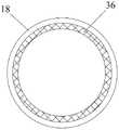
优选地,所述管体还包括密封组件,所述底部管的下部由上至下依次设置有多个孔组,各所述孔组包括多个沿周向设置的通孔,所述密封组件套设安装于所述底部管的外部,所述密封组件包括连接环和固定于所述连接环下端的密封环,所述密封环的内壁上设置有密封圈,所述连接环螺纹套设于所述底部管的外部。Preferably, the pipe body further includes a sealing assembly, a plurality of hole groups are sequentially arranged in the lower part of the bottom pipe from top to bottom, and each hole group includes a plurality of through holes arranged in the circumferential direction, and the sealing assembly It is sleeved and installed on the outside of the bottom pipe. The sealing assembly includes a connecting ring and a sealing ring fixed at the lower end of the connecting ring. The inner wall of the sealing ring is provided with a sealing ring, and the connecting ring is threadedly sleeved on the the outside of the bottom tube.
优选地,所述滴头的内部设置有由上至下依次设置的螺纹连接段、倒锥形孔段和圆孔段,所述螺纹连接段用于与所述底部管连接,所述底部管的内径大于所述圆孔段的内径。Preferably, the inside of the dripper is provided with a threaded connection section, an inverted conical hole section and a circular hole section arranged in sequence from top to bottom, and the threaded connection section is used to connect with the bottom pipe, the bottom pipe The inner diameter is larger than the inner diameter of the circular hole segment.
优选地,所述固定机构包括第一固定组件和第二固定组件,所述第一固定组件包括第一立板、第一弧形板和第一橡胶层,所述第一立板固定于所述支撑板的下表面且位于所述安装孔的一侧,所述第一立板靠近所述安装孔一侧的下部固定有所述第一弧形板,所述第一弧形板的内侧设置有所述第一橡胶层;所述第二固定组件包括第二立板、第二弧形板、第二橡胶层、横板、倾斜加强杆、滑块和多个第二螺钉,所述支撑板的下表面设置有滑槽,所述滑槽位于所述安装孔的另一侧,所述第二立板靠近所述安装孔一侧的下部固定有所述第二弧形板,所述第二弧形板的内侧设置有所述第二橡胶层,所述第二立板远离所述安装孔一侧的下部固定有所述横板,所述横板的上方固定有所述滑块,所述滑块滑动安装于所述滑槽中,所述滑块用于带动所述第二弧形板靠近或远离所述第一弧形板,多个所述第二螺钉用于将所述横板固定于所述支撑板上,所述倾斜加强杆的两端分别固定于所述横板和所述第二立板上。Preferably, the fixing mechanism includes a first fixing component and a second fixing component, the first fixing component includes a first vertical plate, a first arc-shaped plate and a first rubber layer, and the first vertical plate is fixed on the The lower surface of the support plate is located on one side of the installation hole, the first arc-shaped plate is fixed on the lower part of the first vertical plate near the installation hole, and the inner side of the first arc-shaped plate is fixed. The first rubber layer is provided; the second fixing component includes a second vertical plate, a second arc-shaped plate, a second rubber layer, a horizontal plate, an inclined reinforcing rod, a sliding block and a plurality of second screws, the The lower surface of the support plate is provided with a chute, the chute is located on the other side of the installation hole, and the second arc-shaped plate is fixed at the lower part of the second vertical plate close to the side of the installation hole, so The second rubber layer is arranged on the inner side of the second arc-shaped plate, the horizontal plate is fixed on the lower part of the second vertical plate away from the installation hole, and the sliding plate is fixed on the upper part of the horizontal plate. The sliding block is slidably installed in the chute, the sliding block is used to drive the second arc-shaped plate close to or away from the first arc-shaped plate, and a plurality of the second screws are used to The horizontal plate is fixed on the support plate, and both ends of the inclined reinforcing rod are respectively fixed on the horizontal plate and the second vertical plate.
优选地,所述第一弧形板靠近所述第二弧形板的端面上设置有多个卡槽,所述第二弧形板靠近所述第一弧形板的端面上设置有多个卡块,所述卡块与所述卡槽一一对应且结构相匹配。Preferably, the end surface of the first arc-shaped plate close to the second arc-shaped plate is provided with a plurality of clamping grooves, and the end surface of the second arc-shaped plate close to the first arc-shaped plate is provided with a plurality of clamping grooves The card blocks are in one-to-one correspondence with the card slots and have matching structures.
优选地,所述滑块为T形块,所述滑槽为T形槽,各所述第二固定组件包括两个所述滑块。Preferably, the sliding block is a T-shaped block, the sliding groove is a T-shaped groove, and each of the second fixing components includes two sliding blocks.
优选地,所述安装孔的内壁上设置有弹性层。Preferably, an elastic layer is provided on the inner wall of the mounting hole.
本发明相对于现有技术取得了以下技术效果:The present invention has achieved the following technical effects with respect to the prior art:
本发明提供的化学实验用滴管,包括支撑框架、挤压机构、多个管体和多个固定机构,管体包括由上至下依次设置的橡胶头、固定管、调节管、倒锥形管、底部管和滴头,调节管螺纹套设于固定管下端的外部,通过转动调节管能够改变调节管与固定管的相对位置,进而实现管体整体长度的调节,当需要对细长容器中液体进行吸取时,无需更换不同型号的滴管,使得滴管能够匹配不同的使用场景。支撑板上设置有多个安装孔,支撑板的下表面设置有与安装孔一一对应的固定机构,固定管的上端设置于安装孔中,固定机构用于将固定管固定于支撑板上,挤压机构包括挤压柱、挤压板和弹性组件,使用时,通过挤压柱向下按动挤压板能够同时挤压多个橡胶头,将多个管体伸入不同的液体中,松开挤压柱,挤压板在弹性组件的作用下向上运动复位,挤压力消失之后橡胶头复位,使得多个管体同时对液体进行吸取,之后将各管体分别对准不同的需要滴定的容器,向下按动挤压柱实现多个管体中液体的同时滴出,进而使得操作过程简便,提高了工作效率。The dropper for chemical experiments provided by the present invention includes a support frame, a pressing mechanism, a plurality of pipe bodies and a plurality of fixing mechanisms. The pipe body includes a rubber head, a fixing pipe, a regulating pipe and an inverted cone arranged in sequence from top to bottom. The pipe, the bottom pipe and the dripper, the adjusting pipe is threaded on the outside of the lower end of the fixed pipe, and the relative position of the adjusting pipe and the fixed pipe can be changed by rotating the adjusting pipe, thereby realizing the adjustment of the overall length of the pipe body. When sucking medium liquid, there is no need to replace different types of droppers, so that the dropper can match different usage scenarios. The support plate is provided with a plurality of mounting holes, the lower surface of the support plate is provided with a fixing mechanism corresponding to the mounting holes one-to-one, the upper end of the fixing pipe is arranged in the mounting hole, and the fixing mechanism is used to fix the fixing pipe on the supporting plate, The extrusion mechanism includes an extrusion column, an extrusion plate and an elastic component. When in use, the extrusion plate can be pressed down through the extrusion column to simultaneously extrude multiple rubber heads, and multiple pipe bodies can be inserted into different liquids. Loosen the extrusion column, the extrusion plate moves up and resets under the action of the elastic component, and the rubber head resets after the extrusion force disappears, so that multiple tubes can absorb the liquid at the same time, and then each tube body is aligned with different needs. For the titration container, pressing the extrusion column downwards realizes the simultaneous dripping of the liquids in the multiple tubes, thereby making the operation process simple and improving the work efficiency.
附图说明Description of drawings
为了更清楚地说明本发明实施例或现有技术中的技术方案,下面将对实施例中所需要使用的附图作简单地介绍,显而易见地,下面描述中的附图仅仅是本发明的一些实施例,对于本领域普通技术人员来讲,在不付出创造性劳动的前提下,还可以根据这些附图获得其他的附图。In order to more clearly illustrate the embodiments of the present invention or the technical solutions in the prior art, the accompanying drawings required in the embodiments will be briefly introduced below. Obviously, the drawings in the following description are only some of the present invention. In the embodiments, for those of ordinary skill in the art, other drawings can also be obtained according to these drawings without any creative effort.
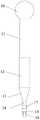
图1为本发明提供的化学实验用滴管的结构示意图;Fig. 1 is the structural representation of the chemical experiment dropper provided by the present invention;
图2为本发明提供的化学实验用滴管中管体的结构示意图;Fig. 2 is the structural representation of the pipe body in the chemical experiment dropper provided by the present invention;
图3为本发明提供的化学实验用滴管中密封环的结构示意图;3 is a schematic structural diagram of a sealing ring in a dropper for chemical experiments provided by the present invention;
图4为本发明提供的化学实验用滴管中滴头的结构示意图;4 is a schematic structural diagram of a dripper in a dripper for chemical experiments provided by the present invention;
图5为本发明提供的化学实验用滴管中第一固定组件的结构示意图;5 is a schematic structural diagram of the first fixing component in the dropper for chemical experiments provided by the present invention;
图6为本发明提供的化学实验用滴管中第二固定组件的结构示意图。FIG. 6 is a schematic structural diagram of the second fixing component in the dropper for chemical experiments provided by the present invention.
附图标记说明:100、化学实验用滴管;1、支撑板;2、导向柱;3、顶板;4、第一螺钉;5、把手;6、挤压柱;7、挤压板;8、弹簧;9、导向块;10、橡胶头;11、固定管;12、调节管;13、倒锥形管;14、底部管;15、滴头;16、通孔;17、连接环;18、密封环;19、螺纹连接段;20、倒锥形孔段;21、圆孔段;22、第一立板;23、第一弧形板;24、第一橡胶层;25、卡槽;26、第二立板;27、第二弧形板;28、第二橡胶层;29、卡块;30、横板;31、倾斜加强杆;32、滑块;33、第二螺钉;34、滑槽;35、弹性层;36、密封圈。Description of reference numerals: 100, dropper for chemical experiments; 1, support plate; 2, guide column; 3, top plate; 4, first screw; 5, handle; 6, squeeze column; 7, squeeze plate; 8 , spring; 9, guide block; 10, rubber head; 11, fixed tube; 12, adjustment tube; 13, inverted conical tube; 14, bottom tube; 15, dripper; 16, through hole; 17, connecting ring; 18. Sealing ring; 19. Threaded connection section; 20. Inverted tapered hole section; 21. Round hole section; 22. First vertical plate; 23. First arc plate; 24. First rubber layer; 25. Clip groove; 26, second vertical plate; 27, second arc plate; 28, second rubber layer; 29, clamping block; 30, horizontal plate; 31, inclined reinforcing rod; 32, slider; 33, second screw ; 34, chute; 35, elastic layer; 36, sealing ring.
具体实施方式Detailed ways
下面将结合本发明实施例中的附图,对本发明实施例中的技术方案进行清楚、完整地描述,显然,所描述的实施例仅仅是本发明一部分实施例,而不是全部的实施例。基于本发明中的实施例,本领域普通技术人员在没有做出创造性劳动前提下所获得的所有其他实施例,都属于本发明保护的范围。The technical solutions in the embodiments of the present invention will be clearly and completely described below with reference to the accompanying drawings in the embodiments of the present invention. Obviously, the described embodiments are only a part of the embodiments of the present invention, but not all of the embodiments. Based on the embodiments of the present invention, all other embodiments obtained by those of ordinary skill in the art without creative efforts shall fall within the protection scope of the present invention.
本发明的目的是提供一种化学实验用滴管,操作过程简便,提高了工作效率,便于调节长度进而能够匹配不同的使用场景。The purpose of the present invention is to provide a dropper for chemical experiments, the operation process is simple, the work efficiency is improved, and the length can be easily adjusted to match different usage scenarios.
为使本发明的上述目的、特征和优点能够更加明显易懂,下面结合附图和具体实施方式对本发明作进一步详细的说明。In order to make the above objects, features and advantages of the present invention more clearly understood, the present invention will be described in further detail below with reference to the accompanying drawings and specific embodiments.
如图1-图6所示,本实施例提供一种化学实验用滴管100,包括支撑框架、挤压机构、多个管体和多个固定机构,支撑框架包括支撑板1、顶板3和多个导向柱2,多个导向柱2固定于支撑板1的上方,顶板3能够拆卸地安装于多个导向柱2的上方;管体包括由上至下依次设置的橡胶头10、固定管11、调节管12、倒锥形管13、底部管14和滴头15,橡胶头10固定于固定管11上,调节管12螺纹套设于固定管11下端的外部,倒锥形管13固定于调节管12的下端,底部管14固定于倒锥形管13的下端,滴头15螺纹套设于底部管14下端的外部,通过转动调节管12能够改变调节管12与固定管11的相对位置,进而实现管体整体长度的调节,当需要对细长容器中液体进行吸取时,无需更换不同型号的滴管,使得滴管能够匹配不同的使用场景。具体地,调节管12、倒锥形管13和底部管14为一体式结构。支撑板1上设置有多个安装孔,支撑板1的下表面设置有与安装孔一一对应的固定机构,固定管11的上端设置于安装孔中,固定机构用于将固定管11固定于支撑板1上,橡胶头10位于支撑板1的上方;挤压机构包括挤压柱6、挤压板7和弹性组件,挤压板7滑动安装于多个导向柱2上,且挤压板7位于橡胶头10与顶板3之间,弹性组件安装于挤压板7与支撑板1之间,挤压柱6固定于挤压板7的顶部,挤压柱6穿过顶板3伸至外部,挤压柱6能够相对于顶板3上下移动。使用时,通过挤压柱6向下按动挤压板7能够同时挤压多个橡胶头10,将多个管体伸入不同的液体中,松开挤压柱6,挤压板7在弹性组件的作用下向上运动复位,挤压力消失之后橡胶头10复位,使得多个管体同时对液体进行吸取,之后将各管体分别对准不同的需要滴定的容器,向下按动挤压柱6实现多个管体中液体的同时滴出,进而使得操作过程简便,提高了工作效率。需要说明的是,当需要单独控制各管体的滴出液体时,可以选择单独挤压各管体的橡胶头10。As shown in FIGS. 1-6 , the present embodiment provides a
具体地,支撑框架还包括多个第一螺钉4,各导向柱2通过一个第一螺钉4与顶板3连接,需要更换管体时,可以在拆卸第一螺钉4之后将顶板3以及挤压板7取下。顶板3的上表面设置有多个把手5,通过设置把手5使得操作时便于握持整个装置。Specifically, the support frame further includes a plurality of first screws 4, and each guide column 2 is connected to the
挤压机构还包括多个导向块9,各导向块9滑动安装于一个导向柱2上,多个导向块9均固定于挤压板7上,通过导向块9与导向柱2相配合对挤压板7的上下运动进行导向。The extrusion mechanism also includes a plurality of guide blocks 9, each guide block 9 is slidably mounted on a guide column 2, and the plurality of guide blocks 9 are fixed on the
弹性组件包括多个弹簧8,各弹簧8的上下两端分别固定于挤压板7的下表面和支撑板1的上表面。The elastic component includes a plurality of springs 8 , and the upper and lower ends of each spring 8 are respectively fixed to the lower surface of the
如图2和图3所示,管体还包括密封组件,底部管14的下部由上至下依次设置有多个孔组,各孔组包括多个沿周向设置的通孔16,密封组件套设安装于底部管14的外部,密封组件包括连接环17和固定于连接环17下端的密封环18,密封环18的内壁上设置有密封圈36,连接环17螺纹套设于底部管14的外部。通过设置多个孔组与密封组件相配合能够控制管体的吸取量,具体地,当需要较大的吸取量时,使得密封环18不覆盖任何孔组,当需要减小吸取量时,向下拧动连接环17使得密封环18覆盖密封一个或多个孔组,由此根据实际需求进行吸取量的调节。As shown in FIG. 2 and FIG. 3 , the pipe body further includes a sealing assembly. The lower part of the
如图4所示,滴头15的内部设置有由上至下依次设置的螺纹连接段19、倒锥形孔段20和圆孔段21,螺纹连接段19用于与底部管14连接,底部管14的内径大于圆孔段21的内径。在吸取液体时将滴头15有底部管14上取下,避免降低吸取效率,当需要较为精准地控制滴液量时,将滴头15安装于底部管14上即可。As shown in FIG. 4 , the inside of the
如图5和图6所示,固定机构包括第一固定组件和第二固定组件,第一固定组件包括第一立板22、第一弧形板23和第一橡胶层24,第一立板22固定于支撑板1的下表面且位于安装孔的一侧,第一立板22靠近安装孔一侧的下部固定有第一弧形板23,第一弧形板23的内侧设置有第一橡胶层24;第二固定组件包括第二立板26、第二弧形板27、第二橡胶层28、横板30、倾斜加强杆31、滑块32和多个第二螺钉33,支撑板1的下表面设置有滑槽34,滑槽34位于安装孔的另一侧,第二立板26靠近安装孔一侧的下部固定有第二弧形板27,第二弧形板27的内侧设置有第二橡胶层28,第二立板26远离安装孔一侧的下部固定有横板30,横板30的上方固定有滑块32,滑块32滑动安装于滑槽34中,滑块32与滑槽34结构相匹配,滑块32用于带动第二弧形板27靠近或远离第一弧形板23,滑块32与滑槽34相配合的结构能够对横板30的运动进行导向,多个第二螺钉33用于将横板30固定于支撑板1上,倾斜加强杆31的两端分别固定于横板30和第二立板26上。第一弧形板23与第二弧形板27初始为分离状态,安装管体时,将固定管11与调节管12拆开,将固定管11由支撑板1上方插入安装孔中并伸至支撑板1下方,固定管11的一侧与第一弧形板23内侧的第一橡胶层24相接触,推动横板30朝向固定管11运动,进而使得第二弧形板27朝向第一弧形板23运动,使得第二弧形板27和第一弧形板23将固定管11夹紧固定,通过第二螺钉33将横板30固定于支撑板1上,之后在固定管11的下方安装调节管12即可。As shown in Figures 5 and 6, the fixing mechanism includes a first fixing component and a second fixing component. The first fixing component includes a first
第一弧形板23靠近第二弧形板27的端面上设置有多个卡槽25,第二弧形板27靠近第一弧形板23的端面上设置有多个卡块29,卡块29与卡槽25一一对应且结构相匹配,当第二弧形板27与第一弧形板23对接时各卡块29插入一个卡槽25中,使得第二弧形板27与第一弧形板23连接地更加牢固。The end surface of the first arc-shaped
于本具体实施例中,滑块32为T形块,滑槽34为T形槽,通过设置为T形块使得第二固定组件在未安装第二螺钉33时能够挂设于支撑板1下方。各第二固定组件包括两个滑块32,各第二固定组件中的两个滑块32对应安装于两个滑槽34中,进而使得第二固定组件滑动时更加稳定。In this specific embodiment, the
于本具体实施例中,安装孔的内壁上设置有弹性层35,进而避免对固定管11造成磕碰。In this specific embodiment, an
本说明书中应用了具体个例对本发明的原理及实施方式进行了阐述,以上实施例的说明只是用于帮助理解本发明的方法及其核心思想;同时,对于本领域的一般技术人员,依据本发明的思想,在具体实施方式及应用范围上均会有改变之处。综上,本说明书内容不应理解为对本发明的限制。In this specification, specific examples are used to illustrate the principles and implementations of the present invention, and the descriptions of the above embodiments are only used to help understand the method and the core idea of the present invention; There will be changes in the specific implementation manner and application scope of the idea of the invention. In conclusion, the contents of this specification should not be construed as limiting the present invention.
Claims (10)
Translated fromChinesePriority Applications (1)
| Application Number | Priority Date | Filing Date | Title |
|---|---|---|---|
| CN202210001326.0ACN114308171B (en) | 2022-01-04 | 2022-01-04 | Burette for chemistry experiments |
Applications Claiming Priority (1)
| Application Number | Priority Date | Filing Date | Title |
|---|---|---|---|
| CN202210001326.0ACN114308171B (en) | 2022-01-04 | 2022-01-04 | Burette for chemistry experiments |
Publications (2)
| Publication Number | Publication Date |
|---|---|
| CN114308171Atrue CN114308171A (en) | 2022-04-12 |
| CN114308171B CN114308171B (en) | 2023-01-31 |
Family
ID=81023539
Family Applications (1)
| Application Number | Title | Priority Date | Filing Date |
|---|---|---|---|
| CN202210001326.0AActiveCN114308171B (en) | 2022-01-04 | 2022-01-04 | Burette for chemistry experiments |
Country Status (1)
| Country | Link |
|---|---|
| CN (1) | CN114308171B (en) |
Citations (13)
| Publication number | Priority date | Publication date | Assignee | Title |
|---|---|---|---|---|
| US6143252A (en)* | 1999-04-12 | 2000-11-07 | The Perkin-Elmer Corporation | Pipetting device with pipette tip for solid phase reactions |
| US6164449A (en)* | 1998-09-08 | 2000-12-26 | Labsystems Oy | Refill pack |
| US20050032241A1 (en)* | 2003-02-26 | 2005-02-10 | Coassin Peter J. | Reagent dispenser and dispensing method |
| CN207287481U (en)* | 2017-10-16 | 2018-05-01 | 淄博市中心医院 | Pipettor for medical inspection |
| CN207694835U (en)* | 2017-12-04 | 2018-08-07 | 福建未来药业有限公司 | A kind of chemistry combined type dropper |
| CN208260794U (en)* | 2018-01-30 | 2018-12-21 | 中国烟草总公司郑州烟草研究院 | The fixed device of chromatogram bottle heating water bath |
| CN209576724U (en)* | 2019-01-16 | 2019-11-05 | 运城学院 | A kind of Special combined dropper for chemical laboratory |
| CN210410784U (en)* | 2019-06-19 | 2020-04-28 | 南京帝基生物科技有限公司 | Medical science inspection pipetting gun |
| CN212167475U (en)* | 2020-03-24 | 2020-12-18 | 南京诺尔曼生物技术有限公司 | Multi-purpose burette structure of plastics for middle school chemistry teaching |
| CN212237348U (en)* | 2020-05-07 | 2020-12-29 | 苏州华兴源创科技股份有限公司 | Pipette, liquid transfer mechanism and liquid transfer equipment |
| CN113245325A (en)* | 2021-06-01 | 2021-08-13 | 哈尔滨学院 | Chemical industry laboratory is with tube cleaning device |
| CN214020878U (en)* | 2020-10-26 | 2021-08-24 | 华中科技大学同济医学院附属协和医院 | A large-caliber viscous liquid suction nozzle |
| KR102333337B1 (en)* | 2021-07-14 | 2021-12-02 | (주)민진 | Echo auto dropper |
- 2022
- 2022-01-04CNCN202210001326.0Apatent/CN114308171B/enactiveActive
Patent Citations (13)
| Publication number | Priority date | Publication date | Assignee | Title |
|---|---|---|---|---|
| US6164449A (en)* | 1998-09-08 | 2000-12-26 | Labsystems Oy | Refill pack |
| US6143252A (en)* | 1999-04-12 | 2000-11-07 | The Perkin-Elmer Corporation | Pipetting device with pipette tip for solid phase reactions |
| US20050032241A1 (en)* | 2003-02-26 | 2005-02-10 | Coassin Peter J. | Reagent dispenser and dispensing method |
| CN207287481U (en)* | 2017-10-16 | 2018-05-01 | 淄博市中心医院 | Pipettor for medical inspection |
| CN207694835U (en)* | 2017-12-04 | 2018-08-07 | 福建未来药业有限公司 | A kind of chemistry combined type dropper |
| CN208260794U (en)* | 2018-01-30 | 2018-12-21 | 中国烟草总公司郑州烟草研究院 | The fixed device of chromatogram bottle heating water bath |
| CN209576724U (en)* | 2019-01-16 | 2019-11-05 | 运城学院 | A kind of Special combined dropper for chemical laboratory |
| CN210410784U (en)* | 2019-06-19 | 2020-04-28 | 南京帝基生物科技有限公司 | Medical science inspection pipetting gun |
| CN212167475U (en)* | 2020-03-24 | 2020-12-18 | 南京诺尔曼生物技术有限公司 | Multi-purpose burette structure of plastics for middle school chemistry teaching |
| CN212237348U (en)* | 2020-05-07 | 2020-12-29 | 苏州华兴源创科技股份有限公司 | Pipette, liquid transfer mechanism and liquid transfer equipment |
| CN214020878U (en)* | 2020-10-26 | 2021-08-24 | 华中科技大学同济医学院附属协和医院 | A large-caliber viscous liquid suction nozzle |
| CN113245325A (en)* | 2021-06-01 | 2021-08-13 | 哈尔滨学院 | Chemical industry laboratory is with tube cleaning device |
| KR102333337B1 (en)* | 2021-07-14 | 2021-12-02 | (주)민진 | Echo auto dropper |
Also Published As
| Publication number | Publication date |
|---|---|
| CN114308171B (en) | 2023-01-31 |
Similar Documents
| Publication | Publication Date | Title |
|---|---|---|
| CN208488418U (en) | A kind of performance liquid chromatographic column | |
| CN114308171A (en) | A dropper for chemical experiments | |
| CN113478408B (en) | Nozzle positioning device based on research of influence of nozzle structure on atomization performance | |
| CN204502469U (en) | A kind of needle-based solid-phase extraction column | |
| CN210674315U (en) | Chromatographic column device | |
| CN210845503U (en) | Syringe type filtering device | |
| CN204866025U (en) | Clamping mechanism of sand mill | |
| CN220443853U (en) | A pipette gun capable of continuously adding samples | |
| CN208554254U (en) | A kind of chemical experiment sampler | |
| CN208902473U (en) | A kind of analytical chemistry fluid sampling device | |
| CN210266693U (en) | A Multifunctional Gas Dispensing Equipment | |
| CN217396870U (en) | A maintenance liquid extrusion device for blood separation | |
| CN204767595U (en) | Extraction device for chemistry experiments | |
| CN109365019B (en) | Test tube capping device | |
| CN221544606U (en) | Experimental coater assembly bracket | |
| CN222105243U (en) | A PCCP pipe pressure testing device | |
| CN220530736U (en) | Chromatographic column structure | |
| CN223307933U (en) | A reactor sampling device | |
| CN112191603A (en) | Contact cleaning device for isolating switch | |
| CN113325056B (en) | Multifunctional molecular biology electrophoresis auxiliary device | |
| CN214971918U (en) | Fast preparative chromatography | |
| CN222724354U (en) | Pipeline-free liquid dropping device for textile printing and dyeing | |
| CN221883094U (en) | A surface soil sampling device | |
| CN219539564U (en) | A mobile phase suction filtration device | |
| CN219266082U (en) | A spectrometer convenient for fixing samples |
Legal Events
| Date | Code | Title | Description |
|---|---|---|---|
| PB01 | Publication | ||
| PB01 | Publication | ||
| SE01 | Entry into force of request for substantive examination | ||
| SE01 | Entry into force of request for substantive examination | ||
| GR01 | Patent grant | ||
| GR01 | Patent grant |