CN114306904A - Medicine leading-in instrument - Google Patents
Medicine leading-in instrumentDownload PDFInfo
- Publication number
- CN114306904A CN114306904ACN202111669981.5ACN202111669981ACN114306904ACN 114306904 ACN114306904 ACN 114306904ACN 202111669981 ACN202111669981 ACN 202111669981ACN 114306904 ACN114306904 ACN 114306904A
- Authority
- CN
- China
- Prior art keywords
- examples
- screw rod
- hole
- gear
- screw
- Prior art date
- Legal status (The legal status is an assumption and is not a legal conclusion. Google has not performed a legal analysis and makes no representation as to the accuracy of the status listed.)
- Granted
Links
- 239000003814drugSubstances0.000titleclaimsabstractdescription91
- 229940079593drugDrugs0.000titleclaimsabstractdescription79
- 238000007789sealingMethods0.000claimsabstractdescription43
- 230000005540biological transmissionEffects0.000claimsabstractdescription24
- 238000010586diagramMethods0.000description17
- 230000033001locomotionEffects0.000description11
- 238000002360preparation methodMethods0.000description9
- 238000000034methodMethods0.000description6
- 239000007788liquidSubstances0.000description4
- 238000012986modificationMethods0.000description3
- 230000004048modificationEffects0.000description3
- 238000005034decorationMethods0.000description2
- 230000004308accommodationEffects0.000description1
- 238000013459approachMethods0.000description1
- 230000003796beautyEffects0.000description1
- 230000000694effectsEffects0.000description1
- 230000010354integrationEffects0.000description1
Images


Landscapes
- Infusion, Injection, And Reservoir Apparatuses (AREA)
Abstract
Description
Translated fromChinese技术领域technical field
本公开大体涉及一种药物导入仪,具体涉及一种具有推进装置的药物导入仪。The present disclosure generally relates to a drug introducer, and in particular, to a drug introducer with a propulsion device.
背景技术Background technique
在医疗领域或医疗美容领域中,使用药液进行治疗是一种常用的手段。通常情况下,药液会储存在储存容器中,在需要治疗时,操作人员会通过药物导入仪将药液引导至治疗区域。In the medical field or medical beauty field, the use of medicinal liquid for treatment is a common method. Usually, the drug solution is stored in a storage container, and when treatment is required, the operator will guide the drug solution to the treatment area through the drug introducer.
药物导入仪一般包括容纳药物的密封管、以及设置于密封管内部且可沿着密封管移动的活塞,在使用时通过推动活塞以使药物流出。目前,大多药物导入仪的活塞需要操作人员手持推进杆以推动活塞。然而,在上述现有的药物导入仪中,由于操作人员是手动推动活塞,因而在导入药物时不容易准确地控制药液流出的速率和流量。The drug introduction device generally includes a sealing tube for accommodating the drug, and a piston disposed inside the sealing tube and movable along the sealing tube. When in use, the piston is pushed to make the drug flow out. Currently, the piston of most drug introducers requires the operator to hold a push rod to push the piston. However, in the above-mentioned conventional drug introduction apparatus, since the operator manually pushes the piston, it is not easy to accurately control the rate and flow rate of the drug liquid during drug introduction.
因此,需要一种具有推进装置的药物导入仪。Therefore, there is a need for a drug introducer with a propulsion device.
发明内容SUMMARY OF THE INVENTION
本公开是有鉴于上述现有技术的状况而提出的,其目的在于提供一种具有推进装置的药物导入仪。The present disclosure is proposed in view of the above-mentioned state of the art, and an object of the present disclosure is to provide a drug introduction device with a propulsion device.
为此,本公开提供了一种药物导入仪,所述药物导入仪包括储药装置和推进装置,所述储药装置包括用于装载药物且具有出料口的密封管、以及设置在所述密封管内且可沿着所述密封管的长度方向移动的活塞,所述推进装置包括装配架以及设置于所述装配架的驱动电机、螺杆、和传动机构;所述装配架具有相对设置的第一装配板和第二装配板,所述第一装配板具有第一通孔并且所述第二装配板具有第二通孔,所述驱动电机具有输出轴,所述螺杆呈柱状且具有设置在外周的外螺纹,所述传动机构具有相互啮合的第一齿轮和第二齿轮,所述第一齿轮套设于所述输出轴,在所述第二齿轮的内周设有与所述螺杆的外螺纹相匹配的内螺纹,并且所述第二齿轮套设于所述螺杆,所述密封管以所述活塞朝向所述第二通孔的方式连接于所述第二装配板远离所述第一装配板的一侧,所述螺杆依次穿过所述第一通孔和所述第二通孔并且所述螺杆的头部抵接于所述活塞。To this end, the present disclosure provides a drug introduction device, the drug introduction device includes a drug storage device and a propelling device, the drug storage device includes a sealing tube for loading a drug and having a discharge port, and a drug storage device provided on the A piston in the sealing tube and movable along the length direction of the sealing tube, the propulsion device includes an assembly frame and a drive motor, a screw rod, and a transmission mechanism arranged on the assembly frame; an assembly plate and a second assembly plate, the first assembly plate has a first through hole and the second assembly plate has a second through hole, the drive motor has an output shaft, the screw rod is cylindrical and has a The outer thread of the outer circumference, the transmission mechanism has a first gear and a second gear that mesh with each other, the first gear is sleeved on the output shaft, and the inner circumference of the second gear is provided with the screw. The external thread matches the internal thread, and the second gear is sleeved on the screw rod, and the sealing tube is connected to the second assembly plate in a way that the piston faces the second through hole and is away from the first assembly plate. On one side of an assembly plate, the screw rod passes through the first through hole and the second through hole in sequence, and the head of the screw rod abuts against the piston.
在本公开所涉及的药物导入仪中,推进装置能够推动储药装置的活塞沿着密封管的长度方向移动,并将位于密封管内的药物推出。推进装置的驱动电极的输出轴带动传动机构转动;传动机构带动螺杆做直线运动,螺杆推动活塞沿着密封管移动;通过控制推进装置的推进速度可以控制药物推出的速率和流量,使准确控制药物推出的操作更加容易便捷。In the drug introduction device according to the present disclosure, the propulsion device can push the piston of the drug storage device to move along the length direction of the sealing tube, and push out the drug in the sealing tube. The output shaft of the driving electrode of the propulsion device drives the transmission mechanism to rotate; the transmission mechanism drives the screw to move in a straight line, and the screw pushes the piston to move along the sealing tube; by controlling the propulsion speed of the propulsion device, the speed and flow of the drug can be controlled, so that the drug can be accurately controlled The launch operation is easier and more convenient.
另外,在本公开所涉及的制备方法中,可选地,所述推进装置包括设置于所述第一装配板且呈中空筒状的引导件,所述引导件具有导向槽并且所述引导件套设于所述螺杆,所述导向槽形成在所述引导件的内周且沿着所述引导件的长度方向延伸;在所述螺杆的尾部设置有沿着径向向外凸起的导向部,所述导向部嵌于所述导向槽。由此,能够减少螺杆跟随传动机构转动的可能性,进一步提高推进装置的驱动精度。In addition, in the preparation method according to the present disclosure, optionally, the propulsion device includes a hollow cylindrical guide provided on the first assembly plate, the guide has a guide groove and the guide sleeved on the screw rod, the guide groove is formed on the inner circumference of the guide piece and extends along the length direction of the guide piece; a guide protruding outward along the radial direction is arranged at the tail of the screw rod part, the guide part is embedded in the guide groove. Thereby, the possibility that the screw rotates following the transmission mechanism can be reduced, and the driving accuracy of the propulsion device can be further improved.
另外,在本公开所涉及的制备方法中,可选地,所述螺杆的外径与所述第一通孔的内径的差值小于所述导向部的宽度或长度。在这种情况下,在螺杆沿着第一通孔移动时,导向部难以通过第一通孔,由此能够通过第一通孔对螺杆进行限位。In addition, in the preparation method involved in the present disclosure, optionally, the difference between the outer diameter of the screw and the inner diameter of the first through hole is smaller than the width or length of the guide portion. In this case, when the screw rod moves along the first through hole, it is difficult for the guide portion to pass through the first through hole, so that the screw rod can be limited by the first through hole.
另外,在本公开所涉及的制备方法中,可选地,在所述密封管远离所述出料口的一端形成有耳状的凸缘。在这种情况下,密封管的凸缘能够起到标记的作用。In addition, in the preparation method involved in the present disclosure, optionally, an ear-shaped flange is formed at one end of the sealing tube away from the discharge port. In this case, the flange of the sealing tube can function as a marking.
另外,在本公开所涉及的制备方法中,可选地,所述第一通孔的直径不小于所述螺杆的直径且小于所述凸缘的最大宽度。在这种情况下,第一通孔能够起到对密封管进行限位的作用。In addition, in the preparation method involved in the present disclosure, optionally, the diameter of the first through hole is not smaller than the diameter of the screw and smaller than the maximum width of the flange. In this case, the first through hole can limit the position of the sealing tube.
另外,在本公开所涉及的制备方法中,可选地,在所述装配架上设置有卡接口,所述螺杆贯穿所述卡接口,并且所述储药装置的凸缘卡接于所述卡接口。由此,储药装置能够以卡接与卡接口的方式与推进装置连接。In addition, in the preparation method involved in the present disclosure, optionally, a card interface is provided on the assembly frame, the screw rod passes through the card interface, and the flange of the medicine storage device is clipped on the card interface. Thereby, the medicine storage device can be connected to the propulsion device in the manner of a snap connection and a snap interface.
另外,在本公开所涉及的制备方法中,可选地,所述螺杆的外径小于所述密封管的内径,在所述螺杆的头部设置有推头,所述推头的外径不大于所述密封管的内径且不小于所述螺杆的外径。由此,螺杆能够通过推头与活塞抵接,推头能够一定程度上改善活塞的受力情况。In addition, in the preparation method involved in the present disclosure, optionally, the outer diameter of the screw is smaller than the inner diameter of the sealing tube, a pusher is provided at the head of the screw, and the outer diameter of the pusher is not equal to It is larger than the inner diameter of the sealing tube and not smaller than the outer diameter of the screw. In this way, the screw can be in contact with the piston through the push head, and the push head can improve the force bearing condition of the piston to a certain extent.
另外,在本公开所涉及的制备方法中,可选地,所述推进装置还包括具有容纳空间的壳体,所述装配架、所述驱动电机、所述螺杆、以及所述传动机构设置于所述容纳空间。由此,壳体能够起到保护内部的零部件以及装饰的作用。In addition, in the preparation method involved in the present disclosure, optionally, the propulsion device further includes a housing having an accommodating space, and the assembling frame, the driving motor, the screw rod, and the transmission mechanism are arranged in the accommodating space. Thereby, the housing can play a role of protecting the internal components and decoration.
另外,在本公开所涉及的制备方法中,可选地,还包括呈柱状的手柄,在所述壳体的外部设置有卡合部,所述卡合部与所述手柄卡合。由此,能够通过手柄对药物导入仪进行握持,便于操作。In addition, in the preparation method involved in the present disclosure, optionally, a cylindrical handle is further included, an engaging portion is provided outside the casing, and the engaging portion is engaged with the handle. Thereby, the drug introduction device can be held by the handle, and the operation is facilitated.
另外,在本公开所涉及的制备方法中,可选地,所述驱动电机以所述输出轴朝向所述第二装配板的方式设置于所述第一装配板,所述第一齿轮设置于所述第二装配板并套设在所述输出轴。由此,能够通过第一装配板和第二装配板稳固地固定第一齿轮和驱动电机。In addition, in the preparation method involved in the present disclosure, optionally, the drive motor is disposed on the first assembly plate in such a manner that the output shaft faces the second assembly plate, and the first gear is disposed on the first assembly plate. The second assembly plate is sleeved on the output shaft. Thereby, the first gear and the drive motor can be stably fixed by the first mounting plate and the second mounting plate.
根据本公开,能够提供一种具有推进装置的药物导入仪。According to the present disclosure, it is possible to provide a drug introducer with a propulsion device.
附图说明Description of drawings
现在将仅通过参考附图的例子进一步详细地解释本公开,其中:The present disclosure will now be explained in further detail by way of example only with reference to the accompanying drawings, wherein:
图1是示出了本公开示例所涉及的储药装置的示意图。FIG. 1 is a schematic diagram illustrating a drug storage device according to an example of the present disclosure.
图2是示出了本公开示例所涉及的推进装置的示意图。FIG. 2 is a schematic diagram illustrating a propulsion device according to an example of the present disclosure.
图3是示出了本公开示例所涉及的螺杆和传动机构配合的示意图。FIG. 3 is a schematic diagram illustrating the cooperation of the screw and the transmission mechanism involved in the example of the present disclosure.
图4是示出了本公开示例所涉及的第一装配板的仰视图。FIG. 4 is a bottom view showing a first mounting plate according to an example of the present disclosure.
图5是示出了本公开示例所涉及的引导件的示意图。FIG. 5 is a schematic diagram illustrating a guide according to an example of the present disclosure.
图6是示出了本公开示例所涉及的基于第一通孔对螺杆进行限位的原理图。FIG. 6 is a schematic diagram illustrating the position-limiting of the screw based on the first through hole according to the example of the present disclosure.
图7是示出了本公开示例所涉及的第二装配板的示意图。FIG. 7 is a schematic diagram showing a second mounting plate involved in an example of the present disclosure.
图8是示出了本公开示例所涉及的壳体的示意图。FIG. 8 is a schematic diagram showing a case according to an example of the present disclosure.
图9是示出了本公开示例所涉及的电池组件的示意图。FIG. 9 is a schematic diagram illustrating a battery assembly involved in an example of the present disclosure.
具体实施方式Detailed ways
以下,参考附图,详细地说明本公开的优选实施方式。在下面的说明中,对于相同的部件赋予相同的符号,省略重复的说明。另外,附图只是示意性的图,部件相互之间的尺寸的比例或者部件的形状等可以与实际的不同。Hereinafter, preferred embodiments of the present disclosure will be described in detail with reference to the accompanying drawings. In the following description, the same reference numerals are assigned to the same components, and overlapping descriptions are omitted. In addition, the drawings are only schematic diagrams, and the ratios of the dimensions of the members, the shapes of the members, and the like may be different from the actual ones.
需要说明的是,本公开中的术语“包括”和“具有”以及它们的任何变形,例如所包括或所具有的一系列步骤或单元的过程、方法、系统、产品或设备不必限于清楚地列出的那些步骤或单元,而是可以包括或具有没有清楚地列出的或对于这些过程、方法、产品或设备固有的其它步骤或单元。It should be noted that the terms "comprising" and "having" in the present disclosure and any modifications thereof, such as a process, method, system, product or device of a series of steps or units included or included are not necessarily limited to those explicitly listed. those steps or units listed, but may include or have other steps or units not expressly listed or inherent to these processes, methods, products or devices.
另外,在本公开的下面描述中涉及的小标题等并不是为了限制本公开的内容或范围,其仅仅是作为阅读的提示作用。这样的小标题既不能理解为用于分割文章的内容,也不应将小标题下的内容仅仅限制在小标题的范围内。In addition, the subheadings and the like mentioned in the following description of the present disclosure are not intended to limit the content or scope of the present disclosure, but only serve as a reminder for reading. Such subheadings can neither be understood to be used to divide the content of the article, nor should the content under the subheadings be limited to the scope of the subheadings.
本公开主要涉及一种具有推进装置的药物导入仪,以下简称药物导入仪。本公开涉及的药物导入仪可以用于储存药物和引导药物至特定区域。The present disclosure mainly relates to a drug introduction device with a propulsion device, hereinafter referred to as a drug introduction device. The drug introducer device involved in the present disclosure can be used to store drugs and guide drugs to specific areas.
在一些示例中,药物导入仪可以包括储药装置和推进装置。其中储药装置用于容纳药物、提供药物。推进装置可以用于将储药装置中的药物推出。在一些示例中,储药装置也可以称为密封管、储液管、储液机构或储药机构。在一些示例中,推进装置也可以称为推进器、推进机构、或推进组件。In some examples, the drug introducer may include a drug storage device and a propelling device. The medicine storage device is used for accommodating medicines and providing medicines. The propulsion device may be used to push the drug out of the drug storage device. In some examples, the drug storage device may also be referred to as a sealing tube, a liquid storage tube, a liquid storage mechanism, or a drug storage mechanism. In some examples, a propulsion device may also be referred to as a propeller, a propulsion mechanism, or a propulsion assembly.
图1是示出了本公开示例所涉及的储药装置10的示意图。FIG. 1 is a schematic diagram illustrating a
参见图1,在一些示例中,储药装置10可以包括密封管11、和活塞12。在一些示例中,储药装置10可以用于装载药物。在一些示例中,密封管11可以具有出料口13。在一些示例中,活塞12可以设置在密封管11内且可沿着密封管11的长度方向移动。Referring to FIG. 1 , in some examples, the
在一些示例中,储药装置10可以包括设置于密封管11的橡皮塞14。在一些示例中,针头15可以插入橡皮塞14以形成出料口13。在一些示例中,当活塞12向橡皮塞14靠近时,位于密封管11内部的药物可以受到活塞12的挤压从出料口13挤出。In some examples, the
在一些示例中,在密封管11远离出料口13的一端形成有耳状的凸缘。在这种情况下,密封管11的凸缘能够起到标记的作用。具体而言,在一些示例中,凸缘可以起到标记密封管11的端部位置、密封管11的周向位置的作用。在一些示例中,可以利用凸缘的标记作用判断密封管11的位置。In some examples, an ear-shaped flange is formed at the end of the sealing
图2是示出了本公开示例所涉及的推进装置100的示意图。图3是示出了本公开示例所涉及的螺杆140和传动机构130配合的示意图。FIG. 2 is a schematic diagram illustrating a
在一些示例中,可以通过本公开所涉及的推进装置100将储药装置10的药物挤出。In some examples, the medication of the
在一些示例中,推进装置100可以包括装配架110、驱动电机120、传动机构130和螺杆140。在一些示例中,驱动电机120、传动机构130、和螺杆140可以设置于装配架110。在一些示例中,驱动电机120、传动机构130、和螺杆140可以统称为驱动机构。在一些示例中,装配架110可以用于对驱动机构进行承载和固定。In some examples, the
在一些示例中,驱动电机120用于提供动力。在一些示例中,驱动电机120可以具有输出轴121。In some examples, the
在一些示例中,传动机构130用于将驱动电机120的动力传递给螺杆140。在一些示例中,传动机构130可以包括相互啮合的第一齿轮131和第二齿轮132。在一些示例中,第一齿轮131可以套设于输出轴121。第二齿轮132与螺杆140螺纹连接。在一些示例中,传动机构130用于将输出轴121的旋转运动转化为螺杆140的直线运动。在一些示例中,在第二齿轮132的内周设有内螺纹。In some examples, the
在一些示例中,螺杆140用于将传动机构130的旋转运动转化为直线运动。在一些示例中,螺杆140呈柱状且具有设置在外周的外螺纹。在一些示例中,螺杆140可以指代丝杆或螺纹杆。在一些示例中,螺杆140的外螺纹可以与第二齿轮132的内螺纹相匹配。在一些示例中,第二齿轮132可以套设于螺杆140。In some examples, the
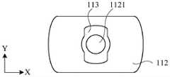
在一些示例中,装配架110可以具有第一装配板111。在一些示例中,装配架110可以具有第二装配板112。在一些示例中,第一装配板111和第二装配板112可以是相对设置的。In some examples, the mounting
在一些示例中,螺杆140可以贯穿第一装配板111和第二装配板112。在一些示例中,第一装配板111可以具有第一通孔1111。在一些示例中,第二装配板112具有第二通孔1121(参见图7)。在一些示例中,螺杆140可以依次穿过第一通孔1111和第二通孔1121。In some examples, the
在一些示例中,推进装置100可以和储药装置10装配在一起。在一些示例中,储药装置10可以装配于装配架110。在一些示例中,密封管11可以以活塞12朝向第二通孔1121的方式连接于第二装配板112远离第一装配板111的一侧。In some examples, the
在一些示例中,储药装置10可以是一次性的。在一些示例中,储药装置10可以卡接于推进装置100。在一些示例中,螺杆140的头部可以抵接于活塞12。由此,储药装置10易于拆卸、安装和更换。在一些示例中,储药装置10的活塞12需要往复运动时,螺杆140也可以与活塞12相连接。In some examples, the
图4是示出了本公开示例所涉及的第一装配板111的仰视图。FIG. 4 is a bottom view showing the first mounting
在一些示例中,第一通孔1111的直径可以不小于螺杆140的直径且小于凸缘的最大宽度。在这种情况下,第一通孔1111能够起到对密封管11进行限位的作用。In some examples, the diameter of the first through
在一些示例中,在装配架110上设置有卡接口113。在一些示例中,螺杆140可以贯穿卡接口113。在一些示例中,卡接口113可以开设在第二装配板112上。在一些示例中,储药装置10的凸缘可以卡接于卡接口113。由此,储药装置10能够以卡接于卡接口113的方式与推进装置100连接。In some examples, a
在一些示例中,螺杆140的外径可以小于密封管11的内径。在一些示例中,在螺杆140的头部可以设置有推头141。在一些示例中,推头141的外径可以不大于密封管11的内径且不小于螺杆140的外径。由此,螺杆140能够通过推头141与活塞12抵接,推头141能够在一定程度上改善活塞12的受力情况。在一些示例中,推头141可以可拆卸地卡接于螺杆140的头部。由此,推头141易于更换。在一些示例中,推头141可以与螺杆140一体成型。In some examples, the outer diameter of the
在本公开所涉及的药物导入仪中,推进装置100能够推动储药装置10的活塞12沿着密封管11的长度方向移动,并将位于密封管11内的药物推出。推进装置100的驱动电极120的输出轴121带动传动机构130转动;传动机构130带动螺杆140做直线运动,螺杆140推动活塞12沿着密封管11移动;通过控制推进装置100的推进速度可以控制药物推出的速率和流量,使准确控制药物推出的操作更加容易便捷。In the drug introduction device involved in the present disclosure, the
图5是示出了本公开示例所涉及的引导件150的示意图。FIG. 5 is a schematic diagram illustrating a
在一些示例中,考虑到在第二齿轮132转动时,可能会带动螺杆140转动,进一步可能导致螺杆140不能即时将第二齿轮132的旋转运动转化为螺杆140本身的直线移动,或螺杆140直线移动时速度波动。因此,在一些示例中,为了提高驱动机构推动活塞12移动的精度,可以通过引导件150限制螺杆140绕其轴线自转,螺杆140在停止转动时能够实时精确地将第二齿轮132的转动运动转化为螺杆140自身的移动。In some examples, considering that when the
在一些示例中,引导件150用于提高螺杆140传动的精确度。在一些示例中,引导件150可以具有导向槽151。对应地,在螺杆140的尾部可以设置有沿着径向向外凸起的导向部142。在一些示例中,导向槽151可以沿着引导件150的长度方向延伸。在一些示例中,导向槽151可以配置为长度方向与螺杆140的长度方向平行。在一些示例中,导向部142可以沿着导向槽151滑动。In some examples, the
在一些示例中,引导件150可以且呈中空筒状。在一些示例中,引导件150可以套设于螺杆140。在一些示例中,导向槽151可以形成在引导件150的内周且沿着引导件150的长度方向延伸。在一些示例中,导向部142可以嵌于导向槽151。由此,能够减少螺杆140跟随传动机构130转动的可能性,进一步提高推进装置100的驱动精度。In some examples, the
在一些示例中,引导件150可以设置于第一装配板111。In some examples, the
图6是示出了本公开示例所涉及的基于第一通孔1111对螺杆140进行限位的原理图。FIG. 6 is a schematic diagram illustrating the position limit of the
在一些示例中,推进装置100可以具有限位功能。具体而言,在一些示例中,推进装置100可以具有对螺杆140进行限位的结构设计。In some examples, the
在一些示例中,推进装置100可以具有限位部。在一些示例中,限位部配置为当螺杆140在移动到预设位置时阻挡螺杆140继续沿原移动方向继续移动。在一些示例中,推进装置100可以具有限位传感装置。In some examples, the
在一些示例中,限位传感装置可以配置为当螺杆140移动到预设位置时给驱动电机120施加制动信号,以使螺杆140停止移动。In some examples, the limit sensing device may be configured to apply a braking signal to the
在一些示例中,螺杆140的外径与第一通孔1111的内径的差值可以小于导向部142的宽度或长度。在这种情况下,在螺杆140沿着第一通孔1111移动时,导向部142难以通过第一通孔1111,由此能够通过第一通孔1111对螺杆140进行限位。另外,通过第一通孔1111的内径限位,还能够简化推进装置100的内部的结构设计。In some examples, the difference between the outer diameter of the
在一些示例中,也可以通过第二通孔1121对螺杆140进行限位。In some examples, the
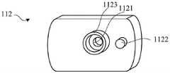
图7是示出了本公开示例所涉及的第二装配板112的示意图。FIG. 7 is a schematic diagram illustrating the
在一些示例中,驱动电机120可以设置于装配架110。在一些示例中,驱动电机120可以设置于第一装配板111。在一些示例中,驱动电机120可以以输出轴121朝向第二装配板112的方式设置于第一装配板111。在一些示例中,第一齿轮131可以套设在输出轴121上。In some examples, the
在一些示例中,第一齿轮131可以设置于装配架110。在一些示例中,第一齿轮131可以设置于第二装配板112上。由此,能够通过第一装配板111和第二装配板112稳固地固定第一齿轮131和驱动电机120。In some examples, the
在一些示例中,第二齿轮132可以设置于装配架110。在一些示例中,第二齿轮132可以设置于第二装配板112上。In some examples, the
在一些示例中,第二装配板112可以用于承载第一齿轮131。在一些示例中,在第二装配板112上可以设置有第一承载部1122。在一些示例中,第一齿轮131可以设置在第一承载部1122上。在一些示例中,第一承载部1122可以呈凸起结构。在一些示例中,凸起结构可以与第一齿轮131相接触。在一些示例中,凸起结构和第一齿轮131的接触面积可以相对较小,以减小第一齿轮131转动时受到的摩擦力。In some examples, the
在一些示例中,第二装配板112可以用于承载第二齿轮132。在一些示例中,在第二装配板112上可以设置有第二承载部1123。在一些还是理智第二齿轮132可以设置在第二承载部1123上。在一些示例中,第二承载部1123可以具有槽状结构。在一些示例中,螺杆140可以贯穿槽状结构。In some examples, the
在一些示例中,第一齿轮131的直径可以小于第二齿轮132的直径。由此,传动机构130可以具有减速的效果。在一些示例中,第一齿轮131的直径也可以大于第二齿轮132的直径。In some examples, the diameter of the
图8是示出了本公开示例所涉及的壳体160的示意图。FIG. 8 is a schematic diagram illustrating a
在一些示例中,推进装置100还包括壳体160。在一些示例中,壳体160内部形成容纳空间。在一些示例中,装配架110、驱动电机120、螺杆140、以及传动机构130可以设置于容纳空间。由此,壳体160能够起到保护内部的零部件以及装饰的作用。In some examples,
在一些示例中,推进装置100可以包括手柄。在一些示例中,手柄可以呈柱状。在壳体160的外部设置有卡合部161。在一些示例中,手柄可以卡合于卡合部161。由此,能够通过手柄对药物导入仪进行握持,便于操作。In some examples,
图9是示出了本公开示例所涉及的电池组件170的示意图。FIG. 9 is a schematic diagram illustrating a
在一些示例中,推进装置100还可以包括电池组件170。在一些示例中,电池组件170可以包括电池、电池固定部171。在一些示例中,电池固定件171可以用于固定电池。在一些示例中,电池固定部171可以包括侧部固定件172和顶部支承件173。在一些示例中,在推进装置100的内部设置有电池组件170可以提高推进装置100内部结构的集成程度,便于携带。In some examples,
在一些示例中,侧部固定件172可以呈板状。在一些示例中,侧部固定件172的形状可以与电池的轮廓匹配。在一些示例中,电池固定件172可以设置于电池与驱动机构之间。侧部固定件172将电池与驱动机构隔开,可以减少驱动机构的零件在运动的过程中碰到电池的可能性。In some examples, the
在一些示例中,顶部支承件173可以呈椎体状。在一些示例中,顶部支承件173可以设置于装配架110上。在一些示例中,顶部支承件173可以设置于第一装配板111上。在一些示例中,顶部支承件173可以贯穿第一装配板111并设置于第二装配板112上。在一些示例中,顶部支承件173用于减少电池在装配时晃动导致接触不良、输出电流不稳定的可能性。在一些示例中,在顶部支承件173上可以设置有弹簧。In some examples, the
在一些示例中,推进装置100的内部可以设置有电路板或控制模块。In some examples, the interior of the
根据本公开,能够提供一种具有推进装置100的药物导入仪。According to the present disclosure, a drug introducer having the
虽然以上结合附图和示例对本公开进行了具体说明,但是可以理解,上述说明不以任何形式限制本公开。本领域技术人员在不偏离本公开的实质精神和范围的情况下可以根据需要对本公开进行变形和变化,这些变形和变化均落入本公开的范围内。Although the present disclosure has been specifically described above with reference to the accompanying drawings and examples, it is to be understood that the above description does not limit the present disclosure in any form. Those skilled in the art can make modifications and changes of the present disclosure as required without departing from the essential spirit and scope of the present disclosure, and these modifications and changes all fall within the scope of the present disclosure.
Claims (10)
Priority Applications (1)
| Application Number | Priority Date | Filing Date | Title |
|---|---|---|---|
| CN202111669981.5ACN114306904B (en) | 2021-12-30 | 2021-12-30 | Drug delivery device |
Applications Claiming Priority (1)
| Application Number | Priority Date | Filing Date | Title |
|---|---|---|---|
| CN202111669981.5ACN114306904B (en) | 2021-12-30 | 2021-12-30 | Drug delivery device |
Publications (2)
| Publication Number | Publication Date |
|---|---|
| CN114306904Atrue CN114306904A (en) | 2022-04-12 |
| CN114306904B CN114306904B (en) | 2024-12-13 |
Family
ID=81020335
Family Applications (1)
| Application Number | Title | Priority Date | Filing Date |
|---|---|---|---|
| CN202111669981.5AActiveCN114306904B (en) | 2021-12-30 | 2021-12-30 | Drug delivery device |
Country Status (1)
| Country | Link |
|---|---|
| CN (1) | CN114306904B (en) |
Citations (14)
| Publication number | Priority date | Publication date | Assignee | Title |
|---|---|---|---|---|
| US6248093B1 (en)* | 1998-10-29 | 2001-06-19 | Minimed Inc. | Compact pump drive system |
| US20030009133A1 (en)* | 2001-04-13 | 2003-01-09 | Kirk Ramey | Drive system for an infusion pump |
| CN201692438U (en)* | 2010-04-20 | 2011-01-05 | 深圳市利泰尔科技有限公司 | Insulin pump for allocating automatic drug administration transmission assembly |
| JP2011005279A (en)* | 2010-09-03 | 2011-01-13 | Panasonic Corp | Medical administration apparatus |
| CN203954331U (en)* | 2014-05-15 | 2014-11-26 | 訾云香 | A kind of insulin pump |
| US20160114098A1 (en)* | 2014-10-24 | 2016-04-28 | Johnson Electric S.A. | Drive mechanism |
| CN205796155U (en)* | 2016-05-23 | 2016-12-14 | 宁波景和电子科技有限公司 | A kind of Novel insulin pump |
| CN107206172A (en)* | 2015-03-13 | 2017-09-26 | 卡贝欧洲有限公司 | Motor-driven delivery device |
| CN108635640A (en)* | 2018-05-25 | 2018-10-12 | 刘斐 | A kind of anesthetic automated injection device |
| CN209809198U (en)* | 2019-02-15 | 2019-12-20 | 江苏耑叶医疗科技有限公司 | Insulin pump with push rod resets dual detection function |
| CN111135381A (en)* | 2019-12-24 | 2020-05-12 | 微泰医疗器械(杭州)有限公司 | Drug delivery drive transmission state monitoring system, method and device |
| CN211357182U (en)* | 2019-11-12 | 2020-08-28 | 刘靖宇 | Medicine injector |
| CN211884798U (en)* | 2019-12-24 | 2020-11-10 | 微泰医疗器械(杭州)有限公司 | Dosing device and dosing pump system |
| CN214017966U (en)* | 2020-05-08 | 2021-08-24 | 中国辐射防护研究院 | Animal experiment medicine injection device |
- 2021
- 2021-12-30CNCN202111669981.5Apatent/CN114306904B/enactiveActive
Patent Citations (16)
| Publication number | Priority date | Publication date | Assignee | Title |
|---|---|---|---|---|
| US6248093B1 (en)* | 1998-10-29 | 2001-06-19 | Minimed Inc. | Compact pump drive system |
| US20030009133A1 (en)* | 2001-04-13 | 2003-01-09 | Kirk Ramey | Drive system for an infusion pump |
| CN201692438U (en)* | 2010-04-20 | 2011-01-05 | 深圳市利泰尔科技有限公司 | Insulin pump for allocating automatic drug administration transmission assembly |
| JP2011005279A (en)* | 2010-09-03 | 2011-01-13 | Panasonic Corp | Medical administration apparatus |
| CN203954331U (en)* | 2014-05-15 | 2014-11-26 | 訾云香 | A kind of insulin pump |
| US20160114098A1 (en)* | 2014-10-24 | 2016-04-28 | Johnson Electric S.A. | Drive mechanism |
| CN205252204U (en)* | 2014-10-24 | 2016-05-25 | 德昌电机(深圳)有限公司 | Medicine transmitter drive arrangement |
| CN107206172A (en)* | 2015-03-13 | 2017-09-26 | 卡贝欧洲有限公司 | Motor-driven delivery device |
| US20180036482A1 (en)* | 2015-03-13 | 2018-02-08 | Carebay Europe Ltd. | Motorized Drug Delivery Device |
| CN205796155U (en)* | 2016-05-23 | 2016-12-14 | 宁波景和电子科技有限公司 | A kind of Novel insulin pump |
| CN108635640A (en)* | 2018-05-25 | 2018-10-12 | 刘斐 | A kind of anesthetic automated injection device |
| CN209809198U (en)* | 2019-02-15 | 2019-12-20 | 江苏耑叶医疗科技有限公司 | Insulin pump with push rod resets dual detection function |
| CN211357182U (en)* | 2019-11-12 | 2020-08-28 | 刘靖宇 | Medicine injector |
| CN111135381A (en)* | 2019-12-24 | 2020-05-12 | 微泰医疗器械(杭州)有限公司 | Drug delivery drive transmission state monitoring system, method and device |
| CN211884798U (en)* | 2019-12-24 | 2020-11-10 | 微泰医疗器械(杭州)有限公司 | Dosing device and dosing pump system |
| CN214017966U (en)* | 2020-05-08 | 2021-08-24 | 中国辐射防护研究院 | Animal experiment medicine injection device |
Also Published As
| Publication number | Publication date |
|---|---|
| CN114306904B (en) | 2024-12-13 |
Similar Documents
| Publication | Publication Date | Title |
|---|---|---|
| CN113633851B (en) | Linear rotary stabilizer for telescoping syringe stopper driver drive assembly | |
| JP3223684B2 (en) | Chemical injection device | |
| US10632253B2 (en) | Liquid medicine administration apparatus and liquid medicine administration unit | |
| JP4758420B2 (en) | Apparatus and method for administering medicinal solution | |
| JP5558668B2 (en) | Syringe assembly and infusion pump assembly incorporating the same | |
| US9033687B2 (en) | Hose pump with planetary gear | |
| EP2029198B1 (en) | Module for a medication injection device | |
| CN107106765B (en) | Liquid medicine feeding device | |
| US20170007774A1 (en) | Telescopic Drive Arrangement | |
| US5380087A (en) | Pharmaceutical mixing container with rotationally mounted housing | |
| WO2005000378A3 (en) | Coupling system for an infusion pump | |
| WO2015121494A1 (en) | Telescopic drive arrangement with oldham coupling | |
| CN114306904A (en) | Medicine leading-in instrument | |
| EP3397312B1 (en) | Syringe positioning apparatus and method | |
| WO2025021233A3 (en) | Medicine injection system | |
| CN101121160A (en) | Glue dispenser and its carrier | |
| WO2015025850A1 (en) | Direct drive unit | |
| CN216798403U (en) | Accommodating box for accommodating liquid reservoir and injection system | |
| EP2174679A1 (en) | Infusion device for drugs | |
| CN222467743U (en) | Liquid sectioning propelling device | |
| JPH08229414A (en) | Electromotive pipette holding and selecting apparatus | |
| JP7614657B2 (en) | Liquid supply device and method | |
| JPH08224501A (en) | Defoaming device | |
| CN115400292B (en) | A container for accommodating a liquid reservoir and an injection system | |
| CN113133941B (en) | Medical injection shaking bottle device |
Legal Events
| Date | Code | Title | Description |
|---|---|---|---|
| PB01 | Publication | ||
| PB01 | Publication | ||
| SE01 | Entry into force of request for substantive examination | ||
| SE01 | Entry into force of request for substantive examination | ||
| GR01 | Patent grant | ||
| GR01 | Patent grant |