CN114305748A - Design method, molding method, storage medium, and system for adding position of reinforcement portion - Google Patents
Design method, molding method, storage medium, and system for adding position of reinforcement portionDownload PDFInfo
- Publication number
- CN114305748A CN114305748ACN202111521653.0ACN202111521653ACN114305748ACN 114305748 ACN114305748 ACN 114305748ACN 202111521653 ACN202111521653 ACN 202111521653ACN 114305748 ACN114305748 ACN 114305748A
- Authority
- CN
- China
- Prior art keywords
- reinforcement
- target
- design method
- distance
- line
- Prior art date
- Legal status (The legal status is an assumption and is not a legal conclusion. Google has not performed a legal analysis and makes no representation as to the accuracy of the status listed.)
- Granted
Links
Images


Classifications
- A—HUMAN NECESSITIES
- A61—MEDICAL OR VETERINARY SCIENCE; HYGIENE
- A61C—DENTISTRY; APPARATUS OR METHODS FOR ORAL OR DENTAL HYGIENE
- A61C7/00—Orthodontics, i.e. obtaining or maintaining the desired position of teeth, e.g. by straightening, evening, regulating, separating, or by correcting malocclusions
Landscapes
- Health & Medical Sciences (AREA)
- Oral & Maxillofacial Surgery (AREA)
- Dentistry (AREA)
- Epidemiology (AREA)
- Life Sciences & Earth Sciences (AREA)
- Animal Behavior & Ethology (AREA)
- General Health & Medical Sciences (AREA)
- Public Health (AREA)
- Veterinary Medicine (AREA)
- Dental Tools And Instruments Or Auxiliary Dental Instruments (AREA)
Abstract
Description
Translated fromChinese技术领域technical field
本发明涉及牙齿矫治技术领域,尤其涉及一种加强部添加位置的设计方法、成型方法及存储介质、系统。The invention relates to the technical field of orthodontic treatment, and in particular, to a design method, a molding method, a storage medium and a system for adding a reinforcing part.
背景技术Background technique
在牙科正畸矫治器使用过程中,需要施加额外的作用力来实现牙科正畸矫治器的重复佩戴及脱卸,当外部作用力很大时,牙科正畸矫治器可能产生变形或断裂,影响牙科正畸矫治器的使用过程,或使得牙科正畸矫治器无法达成矫治效果。During the use of orthodontic appliances, additional force needs to be applied to achieve repeated wearing and dismounting of orthodontic appliances. When the external force is large, the orthodontic appliances may be deformed or broken, affecting the dentistry. The use of orthodontic appliances may make the orthodontic appliances unable to achieve the corrective effect.
发明内容SUMMARY OF THE INVENTION
本发明的目的在于提供一种加强部添加位置的设计方法、成型方法及存储介质、系统,其可通过合理的加强部添加位置的设计方法大大简化加强部于牙颌数字化模型处的添加流程,且成型的牙科正畸矫治器具有较高的强度以避免产生变形或断裂。The purpose of the present invention is to provide a design method, a molding method, a storage medium, and a system for the addition position of the reinforcement part, which can greatly simplify the process of adding the reinforcement part to the digital model of the teeth through a reasonable design method of the reinforcement part addition position. And the formed orthodontic appliance has high strength to avoid deformation or breakage.
为实现上述发明目的之一,本发明一实施方式提供一种加强部添加位置的设计方法,包括步骤:In order to achieve one of the above-mentioned purposes of the invention, an embodiment of the present invention provides a method for designing a position for adding a reinforcing portion, comprising the steps of:
获取牙颌数字化模型;Obtain digital models of teeth and jaws;
计算所述牙颌数字化模型表面目标区域相对于转动轴的惯性矩的参考值;calculating a reference value of the moment of inertia of the target area on the surface of the digital model of the tooth and jaw relative to the rotational axis;
判断所述参考值与第一阈值的大小,若小于,则记录所述目标区域的至少部分区域为加强部添加位置,若不小于,则不记录。Determine the size of the reference value and the first threshold value, if it is smaller than that, record at least a part of the target area as the reinforcement part addition position, if not smaller, not record.
作为本发明一实施方式的进一步改进,步骤“计算所述牙颌数字化模型表面目标区域相对于转动轴的惯性矩的参考值”具体包括:As a further improvement of an embodiment of the present invention, the step "calculating the reference value of the moment of inertia of the target area on the surface of the digital model of the teeth relative to the rotation axis" specifically includes:
于所述牙颌数字化模型表面选取目标线;Selecting a target line on the surface of the digital model of the tooth and jaw;
将所述目标线N等分并获取N+1个目标点;Divide the target line N equally and obtain N+1 target points;
获取经过所述目标点且垂直于所述目标线的N+1个目标截面;Obtain N+1 target sections passing through the target point and perpendicular to the target line;
计算N+1个目标截面相对于转动轴的惯性矩的参考值,其中,N≥1。Calculate the reference value of the inertia moment of N+1 target sections relative to the rotation axis, where N≥1.
作为本发明一实施方式的进一步改进,步骤“获取经过所述目标点且垂直于所述目标线的N+1个目标截面”具体包括:As a further improvement of an embodiment of the present invention, the step "obtaining N+1 target sections passing through the target point and perpendicular to the target line" specifically includes:
于所述牙颌数字化模型表面形成经过任一目标点且垂直于所述目标线的基准线,所述基准线具有第一宽度;forming a reference line passing through any target point and perpendicular to the target line on the surface of the digital model of the dental jaw, the reference line having a first width;
将所述基准线朝远离所述牙颌数字化模型的方向偏移第一偏移量而得到终止线;Offset the reference line in a direction away from the digital model of the dental jaw by a first offset to obtain a termination line;
连接所述基准线及所述终止线而得到垂直于所述目标线的目标截面;Connecting the reference line and the termination line to obtain a target section perpendicular to the target line;
重复上述步骤而得到N+1个目标截面。Repeat the above steps to obtain N+1 target sections.
作为本发明一实施方式的进一步改进,所述第一宽度的范围为0.4mm-20mm,所述第一偏移量大于0.2mm。As a further improvement of an embodiment of the present invention, the range of the first width is 0.4mm-20mm, and the first offset is greater than 0.2mm.
作为本发明一实施方式的进一步改进,步骤“计算N+1个目标截面相对于转动轴的惯性矩的参考值”具体包括:As a further improvement of an embodiment of the present invention, the step "calculating the reference value of the inertia moment of N+1 target sections relative to the rotation axis" specifically includes:
根据每一目标截面的所述第一宽度、所述第一偏移量以及第一高度计算所述目标截面相对于转动轴的惯性矩的参考值,其中,所述第一高度为纵截面上牙齿的咬合面朝向牙龈线的最大高度,所述纵截面经过对应的所述目标点且垂直于近远中方向。A reference value of the moment of inertia of the target section relative to the rotation axis is calculated according to the first width, the first offset, and the first height of each target section, wherein the first height is on the longitudinal section The maximum height of the occlusal surface of the tooth towards the gum line, the longitudinal section passing through the corresponding target point and perpendicular to the mesiodistal direction.
作为本发明一实施方式的进一步改进,步骤“计算N+1个目标截面相对于转动轴的惯性矩的参考值”具体包括:As a further improvement of an embodiment of the present invention, the step "calculating the reference value of the inertia moment of N+1 target sections relative to the rotation axis" specifically includes:
根据每一目标截面上所有点的坐标计算所述目标截面相对于转动轴的惯性矩的参考值。The reference value of the inertia moment of each target section relative to the rotation axis is calculated according to the coordinates of all points on each target section.
作为本发明一实施方式的进一步改进,步骤“判断所述参考值与第一阈值的大小,若小于,则记录所述目标区域的至少部分区域为加强部添加位置,若不小于,则不记录”具体包括:As a further improvement of an embodiment of the present invention, the step "determines the size of the reference value and the first threshold value, if it is less than, then record at least part of the target area as the reinforcement part addition position, if not less than, then do not record "Includes:
判断每一惯性矩的参考值与第一阈值的大小;Determine the size of the reference value of each moment of inertia and the first threshold;
若小于,则将对应的目标点定义为添加点,若不小于,则将对应的目标点定义为非添加点;If it is less than, define the corresponding target point as an added point, if not, define the corresponding target point as a non-added point;
将L个连续的添加点形成的区域定义为一个加强部添加位置而形成M个加强部添加位置,其中,L≥2,M≥1。A region formed by L consecutive addition points is defined as one reinforcement addition position to form M reinforcement addition positions, where L≧2 and M≧1.
作为本发明一实施方式的进一步改进,步骤“将L个连续的添加点形成的区域定义为一个加强部添加位置而形成M个加强部添加位置”之后还包括:As a further improvement of an embodiment of the present invention, the step "defining an area formed by L consecutive addition points as one reinforcement addition position to form M reinforcement addition positions" further includes:
当M≥2时,选取相邻的第K个加强部添加位置及第K+1个加强部添加位置;When M≥2, select the adjacent K-th reinforcement addition position and K+1 reinforcement addition position;
计算第K个加强部添加位置及第K+1个加强部添加位置之间的间隔距离;Calculate the separation distance between the K-th reinforcement addition position and the K+1 reinforcement addition position;
判断所述间隔距离与第二阈值的大小;Judging the size of the separation distance and the second threshold;
若小于,则连接第K个加强部添加位置及第K+1个加强部添加位置,若不小于,则保持第K个加强部添加位置及第K+1个加强部添加位置相互断开,其中,K≥1。If it is less than, connect the Kth reinforcement part addition position and the K+1th reinforcement part addition position; if not, keep the Kth reinforcement part addition position and the K+1th reinforcement part addition position disconnected from each other, Among them, K≥1.
作为本发明一实施方式的进一步改进,步骤“将L个连续的添加点形成的区域定义为一个加强部添加位置而形成M个加强部添加位置”之后还包括:As a further improvement of an embodiment of the present invention, the step "defining an area formed by L consecutive addition points as one reinforcement addition position to form M reinforcement addition positions" further includes:
当M≥2时,选取相邻的第K个加强部添加位置及第K+1个加强部添加位置;When M≥2, select the adjacent K-th reinforcement addition position and K+1 reinforcement addition position;
计算第K个加强部添加位置及第K+1个加强部添加位置之间的非添加点的数量;Calculate the number of non-added points between the K-th reinforcement addition position and the K+1 reinforcement addition position;
判断所述非添加点的数量与第三阈值的大小;Judging the number of the non-added points and the size of the third threshold;
若小于,则连接第K个加强部添加位置及第K+1个加强部添加位置,若不小于,则保持第K个加强部添加位置及第K+1个加强部添加位置相互断开,其中,K≥1。If it is less than, connect the Kth reinforcement part addition position and the K+1th reinforcement part addition position; if not, keep the Kth reinforcement part addition position and the K+1th reinforcement part addition position disconnected from each other, Among them, K≥1.
作为本发明一实施方式的进一步改进,所述设计方法还包括步骤:As a further improvement of an embodiment of the present invention, the design method further includes the steps:
遍历所述牙颌数字化模型表面的所有目标区域并记录所有的加强部添加位置。Traverse all target areas on the surface of the digital model of the jaw and record all reinforcement addition locations.
作为本发明一实施方式的进一步改进,所述加强部添加位置的延伸方向平行于所述牙颌数字化模型的近远中方向、垂直于近远中方向或与近远中方向之间形成的夹角为锐角。As a further improvement of an embodiment of the present invention, the extension direction of the reinforcing part addition position is parallel to the mesio-distal direction of the digital model of the dental jaw, perpendicular to the mesio-distal direction, or a clip formed between the mesio-distal direction and the mesio-distal direction. The angle is an acute angle.
作为本发明一实施方式的进一步改进,所述加强部添加位置位于所述牙颌数字化模型的颊面、舌面或咬合面。As a further improvement of an embodiment of the present invention, the addition position of the reinforcing part is located on the buccal surface, the lingual surface or the occlusal surface of the digital model of the tooth and jaw.
作为本发明一实施方式的进一步改进,所述加强部添加位置对应牙颌数字化模型的前牙区和/或后牙区设置。As a further improvement of an embodiment of the present invention, the added position of the reinforcement portion corresponds to the setting of the anterior tooth area and/or the posterior tooth area of the digital model of the jaw.
作为本发明一实施方式的进一步改进,所述加强部添加位置对应牙颌数字化模型的牙齿表面、邻牙间隙或空泡区的至少其中之一设置。As a further improvement of an embodiment of the present invention, the addition position of the reinforcement portion corresponds to at least one of the tooth surface, the inter-adjacent tooth space or the vacuole area of the digital jaw model.
作为本发明一实施方式的进一步改进,于所述加强部添加位置的延伸方向上,所述加强部添加位置具有第一长度,所述第一长度的范围为0.5mm-150mm。As a further improvement of an embodiment of the present invention, in the extending direction of the reinforcing portion adding position, the reinforcing portion adding position has a first length, and the range of the first length is 0.5 mm-150 mm.
作为本发明一实施方式的进一步改进,所述牙颌数字化模型包括多个加强部添加位置,多个加强部添加位置间隔分布或相互连接。As a further improvement of an embodiment of the present invention, the digital model of the tooth and jaw includes a plurality of reinforcement part addition positions, and the plurality of reinforcement part addition positions are distributed at intervals or connected to each other.
作为本发明一实施方式的进一步改进,所述加强部添加位置位于所述牙颌数字化模型的咬合面的邻牙间隙,所述邻牙间隙连接相邻的第一牙的第一咬合面及第二牙的第二咬合面,所述加强部添加位置于其延伸方向上包括靠近所述第一咬合面的第一端点及靠近所述第二咬合面的第二端点。As a further improvement of an embodiment of the present invention, the reinforcing part is added in the adjacent tooth space of the occlusal surface of the digital model of the dental jaw, and the adjacent tooth space connects the first occlusal surface and the second adjacent tooth of the first tooth. On the second occlusal surface of the two teeth, the reinforcing part addition position includes a first end point close to the first occlusal surface and a second end point close to the second occlusal surface in the extending direction thereof.
作为本发明一实施方式的进一步改进,颊面或舌面与牙龈之间形成牙龈线,于所述牙颌数字化模型的颊面朝向舌面的方向上,所述第一端点与牙龈线的对应区域之间具有第一最大间距,所述第二端点与牙龈线的对应区域之间具有第二最大间距,所述第一最大间距及所述第二最大间距的范围均为0.5mm-4mm。As a further improvement of an embodiment of the present invention, a gum line is formed between the buccal or lingual surface and the gums, and in the direction of the buccal surface of the digital model of the teeth toward the lingual surface, the first end point is connected to the gum line. There is a first maximum distance between the corresponding regions, a second maximum distance between the second end point and the corresponding region of the gum line, and the range of the first maximum distance and the second maximum distance is both 0.5mm-4mm .
作为本发明一实施方式的进一步改进,颊面或舌面与牙龈之间形成牙龈线,于穿过所述目标线且垂直于颊面朝向舌面的方向的截面上,所述第一咬合面包括靠近所述第二咬合面的第一最高点,所述第二咬合面包括靠近所述第一咬合面的第二最高点,所述第一最高点相较于所述第一端点远离牙龈线,所述第二最高点相较于所述第二端点远离牙龈线。As a further improvement of an embodiment of the present invention, a gum line is formed between the buccal or lingual surface and the gum, and on a cross-section passing through the target line and perpendicular to the direction of the buccal surface toward the lingual surface, the first occlusal surface including a first highest point near the second occlusal surface, the second occlusal surface including a second highest point near the first occlusal surface, the first highest point being farther from the first end point the gum line, the second highest point being further away from the gum line than the second end point.
作为本发明一实施方式的进一步改进,于所述牙颌数字化模型的咬合面朝向牙龈线的方向上,所述第一最高点与牙龈线之间具有第一距离,所述第一端点与牙龈线之间具有第二距离,所述第二最高点与牙龈线之间具有第三距离,所述第二端点与牙龈线之间具有第四距离,所述第二距离与所述第一距离的比值不小于20%,所述第四距离与所述第三距离的比值不小于20%。As a further improvement of an embodiment of the present invention, in the direction in which the occlusal surface of the digital model of the teeth faces the gum line, there is a first distance between the first highest point and the gum line, and the first end point is opposite to the gum line. There is a second distance between the gum lines, a third distance between the second highest point and the gum line, a fourth distance between the second end point and the gum line, and the second distance from the first The ratio of the distances is not less than 20%, and the ratio of the fourth distance to the third distance is not less than 20%.
作为本发明一实施方式的进一步改进,所述第二距离与所述第一距离的比值不大于95%,所述第四距离与所述第三距离的比值不大于95%。As a further improvement of an embodiment of the present invention, the ratio of the second distance to the first distance is not greater than 95%, and the ratio of the fourth distance to the third distance is not greater than 95%.
作为本发明一实施方式的进一步改进,所述第二距离为所述第一距离的40%-80%,所述第四距离为所述第三距离的40%-80%。As a further improvement of an embodiment of the present invention, the second distance is 40%-80% of the first distance, and the fourth distance is 40%-80% of the third distance.
为实现上述发明目的之一,本发明一实施方式提供一种加强部添加位置的设计方法,包括步骤:In order to achieve one of the above-mentioned purposes of the invention, an embodiment of the present invention provides a method for designing a position for adding a reinforcing portion, comprising the steps of:
获取牙颌数字化模型;Obtain digital models of teeth and jaws;
获取位于所述牙颌数字化模型表面且经过邻牙间隙的目标区域;acquiring a target area located on the surface of the digital model of the tooth and passing through the inter-adjacent tooth space;
计算所述目标区域相对于转动轴的惯性矩以及邻牙之间的间距;Calculate the inertia moment of the target area relative to the rotation axis and the distance between adjacent teeth;
计算函数f(x,y)的参考值,其中,x为惯性矩,y为邻牙间隙;Calculate the reference value of the function f(x,y), where x is the moment of inertia and y is the gap between adjacent teeth;
判断所述参考值与第四阈值的大小,若小于,则记录所述目标区域为加强部添加位置,若不小于,则不记录。The magnitude of the reference value and the fourth threshold is judged, and if it is smaller than that, the target area is recorded as the reinforcement part addition position, and if it is not smaller than the size, it is not recorded.
作为本发明一实施方式的进一步改进,步骤“计算所述目标区域相对于转动轴的惯性矩”具体包括:As a further improvement of an embodiment of the present invention, the step "calculating the moment of inertia of the target area relative to the rotation axis" specifically includes:
于所述牙颌数字化模型表面选取目标线;Selecting a target line on the surface of the digital model of the tooth and jaw;
将所述目标线N等分并获取N+1个目标点;Divide the target line N equally and obtain N+1 target points;
获取经过所述目标点且垂直于所述目标线的N+1个目标截面;Obtain N+1 target sections passing through the target point and perpendicular to the target line;
计算N+1个目标截面相对于转动轴的惯性矩,其中,N≥1。Calculate the inertia moment of N+1 target sections relative to the rotation axis, where N≥1.
为实现上述发明目的之一,本发明一实施方式提供一种计算机可读存储介质,其上存储有计算机程序,计算机程序被处理器执行时实现如上任一项技术方案所述的加强部添加位置的设计方法中的步骤。In order to achieve one of the above purposes of the invention, an embodiment of the present invention provides a computer-readable storage medium on which a computer program is stored, and when the computer program is executed by a processor, the reinforcement part adding position as described in any one of the above technical solutions is realized. steps in the design method.
为实现上述发明目的之一,本发明一实施方式提供一种加强部的设计系统,设计系统包括存储器和处理器,存储器存储有可在处理器上运行的计算机程序,处理器执行计算机程序时,实现如上任一项技术方案所述的加强部添加位置的设计方法中的步骤。In order to achieve one of the above purposes of the invention, an embodiment of the present invention provides a design system for a reinforcement part, the design system includes a memory and a processor, and the memory stores a computer program that can be run on the processor, and when the processor executes the computer program, The steps in the design method for adding positions of reinforcement parts according to any one of the above technical solutions are realized.
为实现上述发明目的之一,本发明一实施方式提供一种牙科正畸矫治器的成型方法,包括步骤:In order to achieve one of the above purposes of the invention, an embodiment of the present invention provides a method for forming an orthodontic appliance, comprising the steps of:
根据如上任意一项技术方案所述的加强部添加位置的设计方法获取加强部添加位置;Obtaining the reinforcement addition position according to the design method for the reinforcement addition position according to any one of the above technical solutions;
根据加强部添加位置及加强部的结构信息生成牙科正畸矫治器。An orthodontic appliance is generated according to the position where the reinforcement is added and the structural information of the reinforcement.
作为本发明一实施方式的进一步改进,步骤“根据加强部添加位置及加强部的结构信息生成牙科正畸矫治器”具体包括:As a further improvement of an embodiment of the present invention, the step "generating an orthodontic appliance according to the addition position of the reinforcement part and the structural information of the reinforcement part" specifically includes:
判断所述参考值与第五阈值的大小;Judging the size of the reference value and the fifth threshold;
若不小于,则根据加强部的结构信息于所述加强部添加位置处形成加强部,并根据牙颌数字化模型及加强部生成带有空腔的牙科正畸矫治器,所述空腔与所述加强部相互匹配;If it is not smaller than that, then according to the structural information of the reinforcement part, a reinforcement part is formed at the position where the reinforcement part is added, and an orthodontic appliance with a cavity is generated according to the digital model of the teeth and the reinforcement part. The said reinforcements are matched with each other;
若小于,则根据牙颌数字化模型及加强部的结构信息生成带有实心凸嵴的牙科正畸矫治器,所述实心凸嵴与所述加强部相互匹配。If it is smaller than that, an orthodontic appliance with a solid convex ridge is generated according to the digital model of the jaw and the structural information of the reinforcing part, and the solid convex ridge and the reinforcing part are matched with each other.
作为本发明一实施方式的进一步改进,步骤“根据牙颌数字化模型及加强部的结构信息生成带有实心凸嵴的牙科正畸矫治器”具体包括:As a further improvement of an embodiment of the present invention, the step of "generating an orthodontic appliance with a solid convex ridge according to the digital model of the teeth and the structural information of the reinforcement" specifically includes:
根据加强部的结构信息于所述加强部添加位置处形成加强部;forming a reinforcing portion at the reinforcing portion adding position according to the structural information of the reinforcing portion;
根据牙颌数字化模型及加强部生成带有空腔的矫治器本体,所述空腔与所述加强部相互匹配,并于所述空腔内设置填充部而形成实心凸嵴,所述实心凸嵴与所述矫治器本体配合形成牙科正畸矫治器。An appliance body with a cavity is generated according to the digital model of the jaw and the reinforcement part, the cavity and the reinforcement part are matched with each other, and a filling part is arranged in the cavity to form a solid convex ridge, and the solid convex ridge is formed. The ridge cooperates with the appliance body to form an orthodontic appliance.
作为本发明一实施方式的进一步改进,步骤“于所述空腔内设置填充部而形成实心凸嵴”具体包括:As a further improvement of an embodiment of the present invention, the step of "arranging a filling portion in the cavity to form a solid convex ridge" specifically includes:
根据添加的加强部生成填充部;Generate filling parts according to the added reinforcement parts;
将所述填充部固定于所述空腔而形成实心凸嵴。The filling portion is fixed to the cavity to form a solid convex ridge.
作为本发明一实施方式的进一步改进,步骤“根据牙颌数字化模型及加强部的结构信息生成带有实心凸嵴的牙科正畸矫治器”具体包括:As a further improvement of an embodiment of the present invention, the step of "generating an orthodontic appliance with a solid convex ridge according to the digital model of the teeth and the structural information of the reinforcement" specifically includes:
根据牙颌数字化模型生成矫治器本体,所述矫治器本体上设有指示所述加强部添加位置的标记位置,并于所述标记位置处设置实心凸嵴而得到牙科正畸矫治器。The appliance body is generated according to the digital model of the teeth and jaws, the appliance body is provided with a mark position indicating the addition position of the reinforcing part, and a solid convex ridge is set at the mark position to obtain an orthodontic appliance.
作为本发明一实施方式的进一步改进,步骤“于所述标记位置处设置实心凸嵴而得到牙科正畸矫治器”具体包括:As a further improvement of an embodiment of the present invention, the step of "arranging a solid convex ridge at the marked position to obtain an orthodontic appliance" specifically includes:
根据添加的加强部生成实心凸嵴;Generate solid convex ridges based on added reinforcements;
将所述实心凸嵴固定于标记位置处而得到牙科正畸矫治器。The solid convex ridge is fixed at the marked position to obtain an orthodontic appliance.
作为本发明一实施方式的进一步改进,所述结构信息包括加强部的尺寸、截面的外轮廓。As a further improvement of an embodiment of the present invention, the structural information includes the size of the reinforcement portion and the outer contour of the cross-section.
作为本发明一实施方式的进一步改进,远离所述牙颌数字化模型的方向上,所述加强部的截面的外轮廓为矩形、梯形、弧形、三角形、多边形或“M”形。As a further improvement of an embodiment of the present invention, in the direction away from the digital model of the tooth and jaw, the outer contour of the cross-section of the reinforcing part is a rectangle, a trapezoid, an arc, a triangle, a polygon or an "M" shape.
与现有技术相比,本发明一实施方式的有益效果在于:本发明一实施方式的牙颌数字化模型表面目标区域相对于转动轴的惯性矩的参考值可用于表征成型之后的牙科正畸矫治器对应区域相对于转动轴的惯性矩,而惯性矩用于表征牙科正畸矫治器的该区域抵抗弯曲的能力,当参考值较小时,表征该目标区域抵抗弯曲的能力不够,需要在该目标区域添加加强部,后续可在牙科正畸矫治器对应区域形成凸嵴以增加抵抗弯曲的能力,凸嵴的设置可提高牙科正畸矫治器的局部刚度,进而避免牙科正畸矫治器产生变形或断裂;另外,本实施方式直接通过计算牙颌数字化模型表面目标区域相对于转动轴的惯性矩来确定加强部添加位置,加强部添加位置的选取更加精准可靠,进而最终成型的牙科正畸矫治器防变形或断裂的能力更强。Compared with the prior art, the beneficial effect of an embodiment of the present invention is that the reference value of the moment of inertia of the target area on the surface of the digital jaw model of an embodiment of the present invention relative to the rotational axis can be used to characterize the orthodontic treatment after molding The moment of inertia of the corresponding area of the device relative to the rotation axis, and the moment of inertia is used to characterize the ability of this area of the orthodontic appliance to resist bending. When the reference value is small, it indicates that the ability of the target area to resist bending is not enough. Add reinforcement to the area, and subsequently a convex ridge can be formed in the corresponding area of the orthodontic appliance to increase the ability to resist bending. The setting of the convex ridge can improve the local rigidity of the orthodontic appliance, thereby preventing the orthodontic appliance from being deformed or deformed. In addition, this embodiment directly determines the addition position of the reinforcement part by calculating the inertia moment of the target area on the surface of the digital jaw model relative to the rotation axis, and the selection of the reinforcement part addition position is more accurate and reliable, and the final formed orthodontic appliance The ability to prevent deformation or breakage is stronger.
附图说明Description of drawings
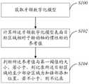
图1是本发明一实施方式的加强部添加位置的设计方法的步骤图;FIG. 1 is a step diagram of a method for designing a reinforcement part addition position according to an embodiment of the present invention;
图2是本发明一实施方式的牙颌数字化模型的示意图;2 is a schematic diagram of a digital model of a dental jaw according to an embodiment of the present invention;
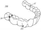
图3是本发明一实施方式的成型的牙科正畸矫治器的示意图;3 is a schematic diagram of a molded orthodontic appliance according to an embodiment of the present invention;
图4是本发明一实施方式的获取目标截面及计算相对于转动轴的惯性矩的参考值的步骤图;4 is a step diagram of acquiring a target cross section and calculating a reference value of the moment of inertia relative to a rotation axis according to an embodiment of the present invention;
图5是本发明一实施方式的获取目标截面的步骤图;5 is a step diagram of obtaining a target cross-section according to an embodiment of the present invention;
图6是本发明一实施方式的获取目标截面的示意图;6 is a schematic diagram of acquiring a target cross-section according to an embodiment of the present invention;
图7是本发明一实施方式的确定加强部添加位置的步骤图;FIG. 7 is a step diagram of determining the addition position of the reinforcement part according to an embodiment of the present invention;
图8是本发明一实施方式的确定加强部添加位置的示意图;FIG. 8 is a schematic diagram of determining the addition position of the reinforcement part according to an embodiment of the present invention;
图9是本发明一具体示例的多个加强部添加位置之间的处理步骤图;FIG. 9 is a process step diagram between a plurality of reinforcement addition positions in a specific example of the present invention;
图10是本发明另一具体示例的多个加强部添加位置之间的处理步骤图;Fig. 10 is a processing step diagram between a plurality of reinforcing part addition positions in another specific example of the present invention;
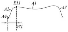
图11是本发明一实施方式的牙颌数字化模型经过目标线且垂直于颊面朝向舌面方向的剖视图;11 is a cross-sectional view of the digital model of the tooth and jaw passing through the target line and perpendicular to the buccal surface toward the lingual surface according to an embodiment of the present invention;
图12是本发明一实施方式的牙颌数字化模型颊面朝向舌面方向剖视图,视图经过第一端点;12 is a cross-sectional view of the buccal surface of the digital dental model of an embodiment of the present invention facing the lingual surface, the view passing through the first end point;
图13是本发明一实施方式的牙颌数字化模型颊面朝向舌面方向剖视图,视图经过第二端点;13 is a cross-sectional view of the buccal surface of the digital dental model of an embodiment of the present invention toward the lingual surface, the view passing through the second end point;
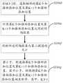
图14是本发明另一实施方式的加强部添加位置的设计方法的步骤图;FIG. 14 is a step diagram of a method for designing a reinforcement part addition position according to another embodiment of the present invention;
图15是本发明一实施方式的加强部的设计系统的处理器示意框图;15 is a schematic block diagram of a processor of a design system for a reinforcement part according to an embodiment of the present invention;
图16是本发明一实施方式的牙科正畸矫治器的成型方法的步骤图;16 is a step diagram of a method for forming an orthodontic appliance according to an embodiment of the present invention;
图17是本发明一实施方式的牙科正畸矫治器的成型方法的示意图;17 is a schematic diagram of a molding method of an orthodontic appliance according to an embodiment of the present invention;
图18是本发明一实施方式的包括空腔的牙科正畸矫治器的示意图;18 is a schematic diagram of an orthodontic appliance including a cavity according to an embodiment of the present invention;
图19是本发明一具体示例的牙科正畸矫治器的成型方法的流程图;19 is a flow chart of a method for forming an orthodontic appliance according to a specific example of the present invention;
图20是本发明另一具体示例的牙科正畸矫治器的成型方法的流程图。Fig. 20 is a flow chart of a method for forming an orthodontic appliance according to another specific example of the present invention.
具体实施方式Detailed ways
以下将结合附图所示的具体实施方式对本发明进行详细描述。但这些实施方式并不限制本发明,本领域的普通技术人员根据这些实施方式所做出的结构、方法、或功能上的变换均包含在本发明的保护范围内。The present invention will be described in detail below with reference to the specific embodiments shown in the accompanying drawings. However, these embodiments do not limit the present invention, and structural, method, or functional changes made by those skilled in the art according to these embodiments are all included in the protection scope of the present invention.
结合图1及图2,本发明一实施方式提供一种加强部添加位置的设计方法,包括步骤:1 and FIG. 2 , an embodiment of the present invention provides a method for designing a position for adding a reinforcing portion, including the steps:
S100:获取牙颌数字化模型100;S100: obtain the
S102:计算牙颌数字化模型100表面目标区域E相对于转动轴的惯性矩的参考值T;S102: Calculate the reference value T of the moment of inertia of the target area E on the surface of the digitized
S104:判断参考值T与第一阈值T1的大小,若小于,则记录目标区域E的至少部分区域为加强部添加位置E1,若不小于,则不记录。S104: Determine the size of the reference value T and the first threshold value T1, if smaller, at least part of the recording target area E is the reinforcement addition position E1, if not smaller, do not record.
这里,“记录目标区域E的至少部分区域为加强部添加位置E1”是指可以是整个目标区域E均记录为加强部添加位置E1,也可以是目标区域E的部分区域记录为加强部添加位置E1。Here, "recording at least part of the target area E as the reinforcement addition position E1" means that the entire target area E may be recorded as the reinforcement addition position E1, or a part of the target area E may be recorded as the reinforcement addition position E1.
另外,加强部添加位置E1即为后续对应加强部的位置,当有多个加强部添加位置E1时,后续并非都需要设置加强部,当某些加强部添加位置E1不满足加强部的添加条件(例如,已经无需添加加强部,或者,加强部添加位置E1不适合添加加强部等)时,后续该些加强部添加位置E1可不添加加强部。In addition, the reinforcement part addition position E1 is the position corresponding to the subsequent reinforcement part. When there are multiple reinforcement part addition positions E1, not all reinforcement parts need to be installed subsequently. When some reinforcement part addition positions E1 do not meet the reinforcement part addition conditions (For example, when it is no longer necessary to add a reinforcing portion, or the reinforcing portion adding position E1 is not suitable for adding a reinforcing portion, etc.), the reinforcing portion may not be added at the subsequent reinforcing portion adding positions E1.
在本实施方式中,结合图3,牙颌数字化模型100表面目标区域E相对于转动轴惯性矩的参考值T可用于表征成型之后的牙科正畸矫治器200对应区域的惯性矩,而惯性矩用于表征牙科正畸矫治器200的该区域抵抗弯曲的能力,当参考值T较小时,表征该目标区域E抵抗弯曲的能力不够,需要在该目标区域E添加加强部,后续可在牙科正畸矫治器200对应区域形成凸嵴20以增加抵抗弯曲的能力,凸嵴20的设置可提高牙科正畸矫治器200的局部刚度,进而避免牙科正畸矫治器200产生变形或断裂。In this embodiment, with reference to FIG. 3 , the reference value T of the target area E on the surface of the
另外,本实施方式直接通过计算牙颌数字化模型100表面目标区域E相对于转动轴的惯性矩来确定加强部添加位置E1,加强部添加位置E1的选取更加精准可靠,进而最终成型的牙科正畸矫治器200防变形或断裂的能力更强。In addition, in this embodiment, the reinforcement part addition position E1 is directly determined by calculating the inertia moment of the target area E on the surface of the
需要说明的是,在利用牙科正畸矫治器200进行矫治的例子中,通常需要把矫治分成多个逐次的阶段(比如20~40个逐次的阶段),每一个阶段对应一个牙科正畸矫治器200,可根据不同阶段的具体需求在对应的牙颌数字化模型100上获取不同参数的加强部添加位置E1,参数包括加强部添加位置E1的数量、位置、形态等。It should be noted that, in the example of using the
在本实施方式中,结合图4至图6,步骤S102具体包括:In this embodiment, with reference to FIGS. 4 to 6 , step S102 specifically includes:
S102a:于牙颌数字化模型100表面选取目标线L1;S102a: Select the target line L1 on the surface of the digital
这里,目标线L1为贴合牙颌数字化模型100表面的曲线,以目标线L1位于牙颌数字化模型100的咬合面A1的邻牙间隙C为例,目标线L1沿牙颌数字化模型100的近远中方向延伸,邻牙间隙C为相邻的第一牙T1的第一咬合面T11及第二牙T2的第二咬合面T21之间的区域。Here, the target line L1 is a curve that fits the surface of the digital
S102b:将目标线L1 N等分并获取N+1个目标点P,当然,也可根据实际情况调整目标点P的分布。S102b: Divide the target line L1 N into equal parts and obtain N+1 target points P. Of course, the distribution of the target points P can also be adjusted according to the actual situation.
S102c:获取经过目标点P且垂直于目标线L1的N+1个目标截面B;S102c: Obtain N+1 target sections B that pass through the target point P and are perpendicular to the target line L1;
具体的,步骤S102c包括:Specifically, step S102c includes:
S1021c:于牙颌数字化模型100表面形成经过任一目标点P且垂直于目标线L1的基准线L2,基准线L2具有第一宽度;S1021c: forming a reference line L2 that passes through any target point P and is perpendicular to the target line L1 on the surface of the digital
这里,考虑到目标线L1及基准线L2均为曲线,难以实现整个目标线L1与整个基准线L2相互垂直,故“垂直于目标线L1的基准线L2”是指在经过目标点P的一小段目标线L1及一小段基准线L2相互垂直,第一宽度即为基准线L2于颊面A2朝向舌面A3方向的宽度,第一宽度的范围为0.4mm-20mm。Here, considering that the target line L1 and the reference line L2 are both curved lines, it is difficult to realize that the entire target line L1 and the entire reference line L2 are perpendicular to each other, so the "reference line L2 perpendicular to the target line L1" refers to a line passing through the target point P. The small target line L1 and the small reference line L2 are perpendicular to each other. The first width is the width of the reference line L2 from the buccal surface A2 to the lingual surface A3. The first width ranges from 0.4 mm to 20 mm.
S1022c:将基准线L2朝远离牙颌数字化模型100的方向偏移第一偏移量L3而得到终止线L4;S1022c: Offset the reference line L2 in a direction away from the digital
S1023c:连接基准线L2及终止线L4而得到垂直于目标线L1的目标截面B;S1023c: connect the reference line L2 and the termination line L4 to obtain a target section B perpendicular to the target line L1;
这里,颊面A2或舌面A3与牙龈之间形成牙龈线A4,“远离牙颌数字化模型100的方向”是指牙颌数字化模型100的牙龈线A4朝向咬合面A1的方向,终止线L4为与基准线L2形状一致的曲线,且终止线L4与基准线L2对应的点之间的间距均为第一偏移量L3。Here, the gum line A4 is formed between the buccal surface A2 or the lingual surface A3 and the gums. The “direction away from the
“连接基准线L2及终止线L4”是指将基准线L2的一端与终止线L4的一端相连,并将基准线L2的另一端与终止线L4的另一端相连,得到的目标截面B垂直于连接该目标点P的一小段目标线L1。"Connecting the reference line L2 and the termination line L4" refers to connecting one end of the reference line L2 with one end of the termination line L4, and connecting the other end of the reference line L2 with the other end of the termination line L4, and the obtained target section B is perpendicular to A short target line L1 connecting the target point P.
需要说明的是,第一偏移量L3大于0.2mm,第一偏移量L3大致对应的是成型的牙科正畸矫治器200的厚度,而目标截面B大致对应的就是牙科正畸矫治器200的纵截面,该纵截面的剖面方向为牙龈线A4朝向咬合面A1的方向,且该纵截面经过的点对应目标点P,故可用目标截面B相对于转动轴的惯性矩表征牙科正畸矫治器200对应区域相对于转动轴的惯性矩。It should be noted that the first offset L3 is greater than 0.2 mm, the first offset L3 roughly corresponds to the thickness of the formed
S1024c:重复上述步骤S1021c至S1023c而得到N+1个目标截面B。S1024c: Repeat the above steps S1021c to S1023c to obtain N+1 target sections B.
这里,由于目标线L1为曲线,至少部分目标截面B是不平行的,通过N等分目标线L1可获取不同的目标截面B。Here, since the target line L1 is a curved line, at least part of the target section B is not parallel, and different target sections B can be obtained by dividing the target line L1 by N.
当然,在其他实施方式中,目标截面B也可通过其他方式获取。Of course, in other embodiments, the target section B can also be obtained in other ways.
S102d:计算N+1个目标截面B相对于转动轴的惯性矩的参考值T,其中,N≥1。S102d: Calculate the reference value T of the inertia moment of N+1 target sections B with respect to the rotation axis, where N≥1.
在一具体示例中,步骤S102d具体包括:In a specific example, step S102d specifically includes:
根据每一目标截面B的第一宽度、第一偏移量L3以及第一高度h计算目标截面B相对于转动轴的惯性矩的参考值T,其中,第一高度h为纵截面上牙齿的咬合面A1朝向牙龈线A4的最大高度,纵截面经过对应的目标点P且垂直于近远中方向。The reference value T of the moment of inertia of the target section B relative to the rotation axis is calculated according to the first width, the first offset L3 and the first height h of each target section B, wherein the first height h is the length of the teeth on the longitudinal section. The maximum height of the occlusal surface A1 towards the gum line A4, the longitudinal section passing through the corresponding target point P and perpendicular to the mesiodistal direction.
在另一具体示例中,步骤S102d具体包括:In another specific example, step S102d specifically includes:
根据每一目标截面B上所有点的坐标计算目标截面B相对于转动轴的惯性矩的参考值T。The reference value T of the inertia moment of the target section B relative to the rotation axis is calculated according to the coordinates of all points on each target section B.
这里,目标截面B上的所有点在全局坐标系下均有对应的坐标点(x,y,z),此时,无需获取目标截面B的第一宽度及第一偏移量L3,可直接根据目标截面B上所有点的坐标计算得到目标截面B相对于转动轴的惯性矩的参考值T。Here, all points on the target section B have corresponding coordinate points (x, y, z) in the global coordinate system. At this time, it is not necessary to obtain the first width and the first offset L3 of the target section B, and you can directly According to the coordinates of all points on the target section B, the reference value T of the inertia moment of the target section B relative to the rotation axis is obtained.
在本实施方式中,结合图7及图8,步骤S104具体包括:In this embodiment, with reference to FIG. 7 and FIG. 8 , step S104 specifically includes:
S104a:判断每一惯性矩的参考值T与第一阈值T1的大小;S104a: determine the size of the reference value T of each moment of inertia and the first threshold value T1;
S104b:若小于,则将对应的目标点P定义为添加点(参考图8中的圆点),若不小于,则将对应的目标点P定义为非添加点(参考图8中的三角形点);S104b: If it is less than, define the corresponding target point P as an added point (refer to the circle point in FIG. 8 ), if not, define the corresponding target point P as a non-added point (refer to the triangle point in FIG. 8 ) );
S104c:将L个连续的添加点形成的区域定义为一个加强部添加位置E1而形成M个加强部添加位置E1,其中,L≥2,M≥1。S104c: Define an area formed by L consecutive addition points as one reinforcement addition position E1 to form M reinforcement addition positions E1, where L≥2 and M≥1.
这里,“L个连续的添加点形成的区域”是指该区域的两端的目标点P为非添加点或不存在目标点P,可以理解的是,在一条目标线L1上,可以包括一个或多个加强部添加位置E1。Here, "the area formed by L consecutive added points" means that the target points P at both ends of the area are non-added points or there is no target point P. It can be understood that, on a target line L1, it can include one or A plurality of reinforcements are added at position E1.
在一具体示例中,结合图9,步骤S104c之后还包括:In a specific example, with reference to FIG. 9 , after step S104c, it further includes:
S104d:当M≥2时,选取相邻的第K个加强部添加位置E1及第K+1个加强部添加位置E1;S104d: when M≥2, select the adjacent Kth reinforcement part addition position E1 and the K+1th reinforcement part addition position E1;
这里,根据前述定义,此时的第K个加强部添加位置E1及第K+1个加强部添加位置E1是相互断开的。Here, according to the aforementioned definition, the K-th reinforcement part addition position E1 and the K+1th reinforcement part addition position E1 at this time are disconnected from each other.
S104e:计算第K个加强部添加位置E1及第K+1个加强部添加位置E1之间的间隔距离;S104e: Calculate the separation distance between the Kth reinforcement part addition position E1 and the K+1th reinforcement part addition position E1;
这里,第K个加强部添加位置E1具有靠近第K+1个加强部添加位置E1的末端目标点P,而第K+1个加强部添加位置E1具有靠近第K个加强部添加位置E1的始端目标点P,目标线L1在末端目标点P及始端目标点P之间的长度即为第K个加强部添加位置E1及第K+1个加强部添加位置E1之间的间隔距离。Here, the Kth reinforcement addition position E1 has an end target point P close to the K+1th reinforcement addition position E1, and the K+1th reinforcement addition position E1 has a close to the Kth reinforcement addition position E1 The start-end target point P, the length of the target line L1 between the end-end target point P and the start-end target point P is the distance between the Kth reinforcement addition position E1 and the K+1th reinforcement addition position E1.
S104f:判断间隔距离与第二阈值T2的大小;S104f: determine the size of the separation distance and the second threshold T2;
S104g:若小于,则连接第K个加强部添加位置E1及第K+1个加强部添加位置E1,若不小于,则保持第K个加强部添加位置E1及第K+1个加强部添加位置E1相互断开,其中,K≥1。S104g: If it is less than, connect the Kth reinforcement part addition position E1 and the K+1th reinforcement part addition position E1; if not less than, keep the Kth reinforcement part addition position E1 and the K+1th reinforcement part addition position E1 The positions E1 are disconnected from each other, where K≥1.
这里,若小于,则表征第K个加强部添加位置E1及第K+1个加强部添加位置E1之间的非添加点的区域长度较短,可忽略该些非添加点而直接将第K个加强部添加位置E1及第K+1个加强部添加位置E1连接形成一整个加强部添加位置E1;若大于,则表征第K个加强部添加位置E1及第K+1个加强部添加位置E1之间的非添加点的区域长度较长,非添加点不可忽略,此时,不对第K个加强部添加位置E1及第K+1个加强部添加位置E1做处理。Here, if it is less than the K-th reinforcement addition position E1 and the K+1 reinforcement addition position E1 between the non-added point region length is short, these non-added points can be ignored and the K-th non-added point can be directly The reinforcement part addition position E1 and the K+1th reinforcement part addition position E1 are connected to form a whole reinforcement part addition position E1; if it is greater than that, it represents the Kth reinforcement part addition position E1 and the K+1th reinforcement part addition position E1 The length of the area of the non-added points between E1 is relatively long, and the non-added points cannot be ignored. In this case, the Kth reinforcement part addition position E1 and the K+1th reinforcement part addition position E1 are not processed.
在另一具体示例中,结合图10,步骤S104c之后还包括:In another specific example, with reference to FIG. 10 , after step S104c, it further includes:
S104d’:当M≥2时,选取相邻的第K个加强部添加位置E1及第K+1个加强部添加位置E1;S104d': when M≥2, select the adjacent Kth reinforcement part addition position E1 and the K+1th reinforcement part addition position E1;
S104e’:计算第K个加强部添加位置E1及第K+1个加强部添加位置E1之间的非添加点的数量;S104e': Calculate the number of non-addition points between the Kth reinforcement addition position E1 and the K+1 reinforcement addition position E1;
S104f’:判断非添加点的数量与第三阈值T3的大小;S104f': determine the number of non-added points and the size of the third threshold T3;
S104g’:若小于,则连接第K个加强部添加位置E1及第K+1个加强部添加位置E1,若不小于,则保持第K个加强部添加位置E1及第K+1个加强部添加位置E1相互断开,其中,K≥1。S104g': if it is less than, connect the Kth reinforcement part addition position E1 and the K+1th reinforcement part addition position E1, if not less than, keep the Kth reinforcement part addition position E1 and the K+1th reinforcement part The addition positions E1 are disconnected from each other, where K≥1.
本具体示例与上一具体示例的区别在于:本具体示例通过计算第K个加强部添加位置E1及第K+1个加强部添加位置E1之间的非添加点的数量来连接两个加强部添加位置E1或保持两个加强部添加位置E1相互断开,本具体示例的其他说明可参考上一具体示例,在此不再赘述。The difference between this specific example and the previous specific example is that this specific example connects two reinforcement parts by calculating the number of non-addition points between the Kth reinforcement part addition position E1 and the K+1th reinforcement part addition position E1 Adding the position E1 or keeping the two reinforcing part adding positions E1 disconnected from each other, for other descriptions of this specific example, reference may be made to the previous specific example, which will not be repeated here.
在本实施方式中,步骤S104之后还包括:In this embodiment, after step S104, it further includes:
遍历牙颌数字化模型100表面的所有目标区域E并记录所有的加强部添加位置E1。Traverse all target areas E on the surface of the
也就是说,重复步骤S100至S104获取牙颌数字化模型100表面所有的加强部添加位置E1。That is to say, steps S100 to S104 are repeated to obtain all reinforcement addition positions E1 on the surface of the
在本实施方式中,结合图11,根据前述加强部添加位置E1的设计方法获取到的加强部添加位置E1于其延伸方向上包括靠近第一咬合面T11的第一端点E11及靠近第二咬合面T21的第二端点E12。In this embodiment, referring to FIG. 11 , the reinforcement addition position E1 obtained according to the design method of the reinforcement addition position E1 includes, in its extending direction, the first end point E11 close to the first occlusal surface T11 and the second end point E11 close to the second occlusal surface T11 . The second end point E12 of the occlusal surface T21.
第一端点E11靠近牙颌数字化模型100的颊面A2、舌面A3设置或居中设置,第二端点E12靠近牙颌数字化模型100的颊面A2、舌面A3设置或居中设置。The first end point E11 is set close to the buccal surface A2 and the lingual surface A3 of the
这里,当第一端点E11及第二端点E12同时靠近牙颌数字化模型100的颊面A2设置,或者同时靠近牙颌数字化模型100的舌面A3设置,又或者同时居中设置时,加强部添加位置E1的延伸方向平行于近远中方向,当然,也可与近远中方向之间存在一个较小的夹角。Here, when the first end point E11 and the second end point E12 are set close to the buccal surface A2 of the digital
当第一端点E11及第二端点E12的其中之一靠近牙颌数字化模型100的颊面A2设置,其中另一靠近牙颌数字化模型100的舌面A3设置时,加强部添加位置E1倾斜设置,加强部添加位置E1的延伸方向与近远中方向之间形成的夹角为锐角。When one of the first end point E11 and the second end point E12 is located close to the buccal surface A2 of the digital
在本实施方式中,于穿过目标线L1且垂直于颊面A2朝向舌面A3的方向的截面上,第一咬合面T11包括靠近第二咬合面T21的第一最高点G1,第二咬合面T21包括靠近第一咬合面T11的第二最高点G2,第一最高点G1相较于第一端点E11远离牙龈线A4,第二最高点G2相较于第二端点E12远离牙龈线A4。In this embodiment, on a cross section passing through the target line L1 and perpendicular to the direction of the buccal surface A2 toward the lingual surface A3, the first occlusal surface T11 includes the first highest point G1 close to the second occlusal surface T21, and the second occlusal surface T11 The surface T21 includes a second highest point G2 near the first occlusal surface T11, the first highest point G1 is farther from the gum line A4 than the first end point E11, and the second highest point G2 is farther from the gum line A4 than the second end point E12 .
此时,可有效控制后续成型在牙科正畸矫治器200上的凸嵴20的高度,避免对颌与该牙科正畸矫治器200接触时接触到凸嵴20,进而避免凸嵴20影响正常的咬合过程。At this time, the height of the
这里,以截面穿过第一牙T1及第二牙T2的牙尖点为例,第一最高点G1对应的是第一牙T1靠近第二牙T2的牙尖R1,第二最高点G2对应的是第二牙T2靠近第一牙T1的牙尖R2。Here, taking the cross-section passing through the cusps of the first tooth T1 and the second tooth T2 as an example, the first highest point G1 corresponds to the cusp R1 of the first tooth T1 close to the second tooth T2, and the second highest point G2 corresponds to The second tooth T2 is close to the cusp R2 of the first tooth T1.
具体的,于牙颌数字化模型100的咬合面A1朝向牙龈线A4的方向(即大致竖直方向)上,第一最高点G1与牙龈线A4之间具有第一距离H1,第一端点E11与牙龈线A4之间具有第二距离H2,第二最高点G2与牙龈线A4之间具有第三距离H3,第二端点E12与牙龈线A4之间具有第四距离H4,第二距离H2与第一距离H1的比值不小于20%,第四距离H4与第三距离H3的比值不小于20%。Specifically, in the direction of the occlusal surface A1 of the digital
另外,第二距离H2与第一距离H1的比值不大于95%,第四距离H4与第三距离H3的比值不大于95%。In addition, the ratio of the second distance H2 to the first distance H1 is not greater than 95%, and the ratio of the fourth distance H4 to the third distance H3 is not greater than 95%.
可选的,第二距离H2为第一距离H1的40%-80%,第四距离H4为第三距离H3的40%-80%。Optionally, the second distance H2 is 40%-80% of the first distance H1, and the fourth distance H4 is 40%-80% of the third distance H3.
在本实施方式中,结合图12及图13,颊面A2或舌面A3与牙龈之间形成牙龈线A4,于牙颌数字化模型100的颊面A2朝向舌面A3的方向上,第一端点E11与牙龈线A4的对应区域之间具有第一最大间距W1,第二端点E12与牙龈线A4的对应区域之间具有第二最大间距W2,第一最大间距W1及第二最大间距W2的范围均为0.5mm-4mm。In this embodiment, referring to FIG. 12 and FIG. 13 , a gum line A4 is formed between the buccal surface A2 or the lingual surface A3 and the gums, and the first end of the
这里,“牙龈线A4的对应区域”是指连接具有凸嵴20的待矫治牙齿的牙龈线A4区域。Here, the "corresponding area of the gum line A4" refers to the area of the gum line A4 connecting the teeth to be treated with the
可选的,第一最大间距W1及第二最大间距W2的范围均为1mm-2.5mm。Optionally, the ranges of the first maximum distance W1 and the second maximum distance W2 are both 1 mm-2.5 mm.
第一间距W1及第二间距W2为颊面A2朝向舌面A3方向上的间距,通过设置合理的第一间距W1及第二间距W2,可提高后续成型的牙科正畸矫治器200对待矫治牙齿的包裹性。The first distance W1 and the second distance W2 are the distances between the buccal surface A2 and the lingual surface A3. By setting a reasonable first distance W1 and a second distance W2, the teeth to be treated in the
在其他实施方式中,加强部添加位置E1除了位于牙颌数字化模型100的咬合面A1之外,还可位于牙颌数字化模型100的颊面A2或舌面A3。In other embodiments, the reinforcement portion addition position E1 may be located on the buccal surface A2 or the lingual surface A3 of the digital
加强部添加位置E1对应牙颌数字化模型100的前牙区和/或后牙区设置。The reinforcement part addition position E1 corresponds to the setting of the anterior teeth area and/or the posterior teeth area of the
加强部添加位置E1对应牙颌数字化模型100的牙齿表面、邻牙间隙或空泡区的至少其中之一设置。The reinforcement part addition position E1 is set corresponding to at least one of the tooth surface, the adjacent tooth space or the vacuole area of the
这里,“至少其中之一”是指一个加强部添加位置E1可同时覆盖颌数字化模型100的牙齿表面、邻牙间隙或空泡区中的一个或多个区域。Here, "at least one of them" means that one reinforcing part adding position E1 can simultaneously cover one or more areas of the tooth surface, the inter-adjacent tooth space or the vacuole area of the
加强部添加位置E1可有多种延伸方向,例如,加强部添加位置E1的延伸方向平行于近远中方向,或者,加强部添加位置E1的延伸方向垂直于近远中方向,又或者,加强部添加位置E1的延伸方向与近远中方向之间形成的夹角为锐角,且加强部添加位置E1呈直线型或曲线型。The reinforcement addition position E1 may have various extension directions, for example, the extension direction of the reinforcement addition position E1 is parallel to the mesio-distal direction, or the extension direction of the reinforcement addition position E1 is perpendicular to the mesio-distal direction, or, the reinforcement The angle formed between the extension direction of the part addition position E1 and the mesio-distal direction is an acute angle, and the reinforcement part addition position E1 is linear or curved.
另外,于加强部添加位置E1的延伸方向上,加强部添加位置E1具有第一长度,第一长度的范围为0.5mm-150mm。In addition, in the extending direction of the reinforcing portion adding position E1, the reinforcing portion adding position E1 has a first length, and the range of the first length is 0.5 mm-150 mm.
牙颌数字化模型100包括多个加强部添加位置E1,多个加强部添加位置E1间隔分布或相互连接。The
在本发明另一实施方式中,结合图14,加强部添加位置的设计方法包括步骤:In another embodiment of the present invention, with reference to FIG. 14 , the design method for the addition position of the reinforcing part includes the steps:
S200:获取牙颌数字化模型100’;S200: Obtain the 100' digital model of the teeth and jaws;
S202:获取位于牙颌数字化模型100’表面且经过邻牙间隙C的目标区域E;S202: Acquire the target area E located on the surface of the digital dental model 100' and passing through the adjacent tooth space C;
这里,以目标区域E位于牙颌数字化模型100’的咬合面A1的邻牙间隙C为例,但不以此为限,本实施方式的邻牙间隙C也可位于颊面A2或舌面A3。Here, it is taken as an example that the target area E is located in the adjacent tooth space C of the occlusal surface A1 of the occlusal surface A1 of the
S204:计算目标区域E相对于转动轴的惯性矩以及邻牙之间的间距;S204: Calculate the inertia moment of the target area E relative to the rotation axis and the distance between adjacent teeth;
S206:计算函数f(x,y)的参考值T’,其中,x为惯性矩,y为邻牙之间的间距;S206: Calculate the reference value T' of the function f(x, y), where x is the moment of inertia, and y is the distance between adjacent teeth;
这里,函数f(x,y)为与参数x、y相关的函数,即x、y均对参考值T’有影响,“邻牙之间的间距”为两颗牙之间的夹缝的宽度。Here, the function f(x,y) is a function related to the parameters x and y, that is, both x and y have an influence on the reference value T', and the "spacing between adjacent teeth" is the width of the gap between the two teeth .
S208:判断参考值T’与第四阈值T4的大小,若小于,则记录目标区域E为加强部添加位置E1,若不小于,则不记录。S208: Determine the size of the reference value T' and the fourth threshold value T4. If it is smaller than the size, the recording target area E is the reinforcement part addition position E1. If it is not smaller than the size, it is not recorded.
可以看到,本实施方式与上一实施方式的区别在于:本实施方式的参考值T’为函数f(x,y)的数值,即参考值T’不仅受到惯性矩的影响,还受到邻牙之间的间距的影响,通过考虑多个参数(即惯性矩及邻牙之间的间距)可提高加强部添加位置E1的精准性及可靠性,进而进一步提高最终成型的牙科正畸矫治器200的防变形或断裂的能力。It can be seen that the difference between this embodiment and the previous embodiment is that the reference value T' of this embodiment is the value of the function f(x, y), that is, the reference value T' is not only affected by the moment of inertia, but also affected by the adjacent The influence of the spacing between teeth, by considering multiple parameters (ie moment of inertia and spacing between adjacent teeth) can improve the accuracy and reliability of the addition position E1 of the reinforcement, and further improve the final formed
本实施方式的其他说明可参考上一实施方式,例如惯性矩的获取、加强部添加位置E1的获取等等,在此不再赘述。For other descriptions of this embodiment, reference may be made to the previous embodiment, such as the acquisition of the moment of inertia, the acquisition of the reinforcement portion addition position E1, and the like, which will not be repeated here.
本发明一实施方式还提供一种计算机可读存储介质,其上存储有计算机程序,计算机程序被处理器执行时实现如上所述的加强部添加位置的设计方法中的步骤。An embodiment of the present invention further provides a computer-readable storage medium on which a computer program is stored, and when the computer program is executed by a processor, implements the steps in the above-described method for designing a reinforcement portion adding position.
结合图15,本发明一实施方式还提供一种加强部的设计系统400,设计系统400包括存储器和处理器40,存储器存储有可在处理器上运行的计算机程序,处理器40执行计算机程序时,实现如上所述的加强部添加位置的设计方法中的步骤。15, an embodiment of the present invention further provides a design system 400 for a reinforcement part, the design system 400 includes a memory and a
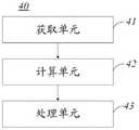
这里,结合前述一实施方式的加强部添加位置的设计方法的说明,处理器40包括如下单元:Here, with reference to the description of the method for designing the reinforcement portion addition position in the foregoing embodiment, the
获取单元41,用于获取牙颌数字化模型100;an
计算单元42,用于计算牙颌数字化模型100表面目标区域E相对于转动轴的惯性矩的参考值T;The
处理单元43,用于判断参考值T与第一阈值T1的大小,若小于,则记录目标区域E的至少部分区域为加强部添加位置E1,若不小于,则不记录。The
在其他实施方式中,结合前述另一实施方式的加强部添加位置的设计方法的说明,处理器40中的各个单元还可是用于执行如下步骤:In other embodiments, with reference to the description of the method for designing the reinforcement portion addition position in the foregoing other embodiment, each unit in the
获取单元41用于获取牙颌数字化模型100’,以及获取位于牙颌数字化模型100’表面且经过邻牙间隙C的目标区域E;The acquiring
计算单元42用于计算目标区域E相对于转动轴的惯性矩以及邻牙之间的间距,以及计算函数f(x,y)的参考值T’,其中,x为惯性矩,y为邻牙之间的间距;The
处理单元43用于判断参考值T’与第四阈值T4的大小,若小于,则记录目标区域E为加强部添加位置E1,若不小于,则不记录。The
需要说明的是,处理器40的各个单元还可用于执行前述设计方法中的其他步骤,具体可参考前述说明,在此不再赘述。It should be noted that each unit of the
本发明一实施方式还提供一种牙科正畸矫治器的成型方法,这里,以加强部300位于咬合面A1为例作说明。An embodiment of the present invention also provides a method for forming an orthodontic appliance. Here, the
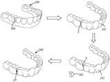
结合图16至图18,成型方法包括步骤:16 to 18, the molding method includes the steps:
S300:根据如上所述的加强部添加位置的设计方法获取加强部添加位置E1;S300: Acquire the reinforcement part addition position E1 according to the design method for the reinforcement part addition position as described above;
S302:根据加强部添加位置E1及加强部300的结构信息生成牙科正畸矫治器200。S302 : Generate the
这里,加强部300的结构信息包括加强部300的尺寸、截面的外轮廓等,有了加强部添加位置E1和加强部300的结构信息之后,便可通过合适的工艺方法生产牙科正畸矫治器200。Here, the structural information of the reinforcing
这里,于牙颌数字化模型的颊面A2朝向舌面A3的方向上,加强部300的截面的外轮廓为矩形、梯形、弧形、三角形、多边形或“M”形。Here, in the direction of the buccal surface A2 of the digital dental model toward the lingual surface A3, the outer contour of the cross-section of the reinforcing
这里,外轮廓是指单个凸嵴10的外轮廓,“M”形是指外轮廓存在一个或多个凹陷,至于凹陷的程度不作限定。Here, the outer contour refers to the outer contour of a single convex ridge 10 , the “M” shape refers to the presence of one or more depressions in the outer contour, and the degree of depression is not limited.
结合图18至图20,步骤S302具体包括:18 to 20, step S302 specifically includes:
判断参考值T(或参考值T’)与第五阈值T5的大小;Determine the size of the reference value T (or reference value T') and the fifth threshold value T5;
若不小于,则根据加强部300的结构信息于加强部添加位置E1处形成加强部300,并根据牙颌数字化模型100及加强部300生成带有空腔S的牙科正畸矫治器200,空腔S与加强部300相互匹配;If it is not smaller than that, then according to the structural information of the
若小于,则根据牙颌数字化模型100及加强部300的结构信息生成带有实心凸嵴20的牙科正畸矫治器200,实心凸嵴20与加强部300相互匹配。If it is smaller than that, the
这里,当参考值T较大时,结合图18,可直接用空腔S作为空心的凸嵴20,空腔S足够用于增大牙科正畸矫治器200的局部强度,进而提高牙科正畸矫治器200抵抗弯曲的能力。Here, when the reference value T is large, referring to FIG. 18 , the cavity S can be directly used as the hollow
当参考值T较小时,结合图19及图20,需要通过实心凸嵴20来辅助增大牙科正畸矫治器200的局部强度,进而保证牙科正畸矫治器200具有足够强的抵抗弯曲的能力。When the reference value T is small, with reference to FIG. 19 and FIG. 20 , the solid
在一具体示例中,结合图19,步骤“根据牙颌数字化模型100及加强部300的结构信息生成带有实心凸嵴20的牙科正畸矫治器200”具体包括:In a specific example, with reference to FIG. 19 , the step “generating an
根据加强部300的结构信息于加强部添加位置E1处形成加强部300;forming the
根据牙颌数字化模型100及加强部300生成带有空腔S的矫治器本体201,空腔S与加强部300相互匹配,并于空腔S内设置填充部202而形成实心凸嵴20,实心凸嵴20与矫治器本体201配合形成牙科正畸矫治器200。The
其中,步骤“于空腔S内设置填充部202而形成实心凸嵴20”具体包括:Wherein, the step of "arranging the filling
根据添加的加强部300生成填充部202;generating the filling
将填充部202固定于空腔S而形成实心凸嵴20。The filling
也就是说,填充部202为预成型的填充部202,且填充部202靠近空腔S的外轮廓与空腔S的内壁相互匹配,填充部202及空腔S可配合形成实心凸嵴20。That is, the filling
当然,填充部202也通过填充及固化工艺直接成型于空腔S内。Of course, the filling
在另一具体示例中,结合图20,步骤“根据牙颌数字化模型100及加强部300的结构信息生成带有实心凸嵴20的牙科正畸矫治器200”具体包括:In another specific example, referring to FIG. 20 , the step “generating an
根据牙颌数字化模型100’生成矫治器本体201’,矫治器本体201’上设有指示加强部添加位置E1的标记位置E1’,并于标记位置E1’处设置实心凸嵴20’而得到牙科正畸矫治器200’。The
其中,步骤“于标记位置E1’处设置实心凸嵴20’而得到牙科正畸矫治器200’”具体包括:Wherein, the step "arrange the solid convex ridge 20' at the marked position E1' to obtain the orthodontic appliance 200'" specifically includes:
根据添加的加强部300’生成实心凸嵴20’;generating solid convex ridges 20' from the added reinforcements 300';
将实心凸嵴20’固定于标记位置E1’处而得到牙科正畸矫治器200’。The solid convex ridge 20' is fixed at the marked position E1' to obtain an orthodontic appliance 200'.
也就是说,实心凸嵴20’为预成型的实心凸嵴20’,标记位置E1’位于矫治器本体201’的外表面,可直接将实心凸嵴20’固定于标记位置E1’而形成牙科正畸矫治器200’。That is to say, the solid convex ridge 20' is a pre-shaped solid convex ridge 20', the marking position E1' is located on the outer surface of the appliance body 201', and the solid convex ridge 20' can be directly fixed to the marking position E1' to form a dental Orthodontic appliance 200'.
当然,实心凸嵴20’也可通过涂布及固化工艺直接成型于标记位置E1’处。Of course, the solid convex ridge 20' can also be directly formed at the marked position E1' through a coating and curing process.
在本实施方式中,以最终成型的牙科正畸矫治器200为例,对应前述加强部添加位置的设计方法中的加强部添加位置E1的多种具体设计,凸嵴20(包括空腔S、实心凸嵴20、20’)也具有多种具体设计。In this embodiment, taking the finally formed
例如,凸嵴20对应待矫治牙齿的前牙区和/或后牙区设置,凸嵴20位于矫治器本体201的颊面A2、舌面A3或咬合面A1,凸嵴20对应待矫治牙齿的牙齿表面、邻牙间隙或空泡区的至少其中之一设置。For example, the
这里,“牙齿表面”是指每颗待矫治牙齿的靠近颊面的表面、靠近舌面的表面或咬合面,“邻牙间隙”是指相邻的两颗待矫治牙齿之间的区域,“空泡区”是指拔牙区域或者是较大缝隙的区域,“至少其中之一”是指一个凸嵴20可同时覆盖待矫治牙齿的牙齿表面、邻牙间隙或空泡区中的一个或多个区域。Here, "dental surface" refers to the buccal, lingual or occlusal surface of each tooth to be orthopedic, and "interdental space" refers to the area between two adjacent teeth to be orthopedic," "Vacuole area" refers to a tooth extraction area or an area of a larger gap, and "at least one of them" means that a
需要说明的是,邻牙间隙具体是指第一牙T1靠近第二牙T2的侧面,以及第二牙T2靠近第一牙T1的侧面,当第一牙T1与第二牙T2之间具有较大的缝隙时,邻牙间隙P不包括该缝隙,该缝隙可定义为空泡区。It should be noted that the adjacent tooth space specifically refers to the side of the first tooth T1 close to the second tooth T2, and the side of the second tooth T2 close to the first tooth T1. When there is a large gap, the gap between adjacent teeth P does not include the gap, and the gap can be defined as a vacuole area.
凸嵴20可有多种延伸方向,例如,凸嵴20的延伸方向平行于近远中方向,或者,凸嵴20的延伸方向垂直于近远中方向,又或者,凸嵴20的延伸方向与近远中方向之间形成的夹角为锐角,且凸嵴20呈直线型或曲线型。The
牙科正畸矫治器200可包括位于矫治器本体201的一个凸嵴20或多个凸嵴20。The
当有多个凸嵴20时,多个凸嵴20间隔分布,或者,多个凸嵴20相互连接。When there are a plurality of
在本实施方式中,矫治器本体201围设形成腔体S’,通过在矫治器本体201上设置朝远离空腔S’的方向凸伸的凸嵴20,可提高整个牙科正畸矫治器200的相对于转动轴的惯性矩,该惯性矩可以提高牙科正畸矫治器200在朝远离空腔S’的方向上抵抗弯曲的能力,而远离空腔S’的方向是牙科正畸矫治器200摘取时主要的施力方向,即凸嵴20的设置可提高正畸矫治器200的局部刚度,进而避免牙科正畸矫治器200产生变形或断裂。In the present embodiment, the
另外,本实施方式的牙科正畸矫治器200直接包括凸嵴20,患者直接佩戴牙科正畸矫治器200即可达到上述效果,使用方便,用户体验较佳。In addition, the
应当理解,虽然本说明书按照实施方式加以描述,但并非每个实施方式仅包含一个独立的技术方案,说明书的这种叙述方式仅仅是为清楚起见,本领域技术人员应当将说明书作为一个整体,各实施方式中的技术方案也可以经适当组合,形成本领域技术人员可以理解的其他实施方式。It should be understood that although this specification is described in terms of embodiments, not each embodiment only includes an independent technical solution. This description in the specification is only for the sake of clarity, and those skilled in the art should take the specification as a whole, and each The technical solutions in the embodiments can also be appropriately combined to form other embodiments that can be understood by those skilled in the art.
上文所列出的一系列的详细说明仅仅是针对本发明的可行性实施方式的具体说明,它们并非用以限制本发明的保护范围,凡未脱离本发明技艺精神所作的等效实施方式或变更均应包含在本发明的保护范围之内。The series of detailed descriptions listed above are only specific descriptions for the feasible embodiments of the present invention, and they are not used to limit the protection scope of the present invention. Changes should all be included within the protection scope of the present invention.
Claims (34)
Translated fromChinesePriority Applications (2)
| Application Number | Priority Date | Filing Date | Title |
|---|---|---|---|
| CN202111521653.0ACN114305748B (en) | 2021-12-13 | 2021-12-13 | Design method, molding method, storage medium and system for adding position of reinforcement part |
| PCT/CN2022/138728WO2023109822A1 (en) | 2021-12-13 | 2022-12-13 | Design method for reinforcement portion addition position, forming method, storage medium, and system |
Applications Claiming Priority (1)
| Application Number | Priority Date | Filing Date | Title |
|---|---|---|---|
| CN202111521653.0ACN114305748B (en) | 2021-12-13 | 2021-12-13 | Design method, molding method, storage medium and system for adding position of reinforcement part |
Publications (2)
| Publication Number | Publication Date |
|---|---|
| CN114305748Atrue CN114305748A (en) | 2022-04-12 |
| CN114305748B CN114305748B (en) | 2025-06-20 |
Family
ID=81051140
Family Applications (1)
| Application Number | Title | Priority Date | Filing Date |
|---|---|---|---|
| CN202111521653.0AActiveCN114305748B (en) | 2021-12-13 | 2021-12-13 | Design method, molding method, storage medium and system for adding position of reinforcement part |
Country Status (2)
| Country | Link |
|---|---|
| CN (1) | CN114305748B (en) |
| WO (1) | WO2023109822A1 (en) |
Cited By (2)
| Publication number | Priority date | Publication date | Assignee | Title |
|---|---|---|---|---|
| WO2023109822A1 (en)* | 2021-12-13 | 2023-06-22 | 无锡时代天使生物科技有限公司 | Design method for reinforcement portion addition position, forming method, storage medium, and system |
| WO2023109821A1 (en)* | 2021-12-13 | 2023-06-22 | 无锡时代天使生物科技有限公司 | Dental orthodontic appliance provided with protruding ridge |
Citations (13)
| Publication number | Priority date | Publication date | Assignee | Title |
|---|---|---|---|---|
| US20040109733A1 (en)* | 2002-12-02 | 2004-06-10 | Safety-Fabrique De Carbure De Tungstene Et D'outillage | Cutting insert including a bracing layer |
| US20060105286A1 (en)* | 2004-11-17 | 2006-05-18 | 3M Innovative Properties Company | Computing final occlusion with respect to torque loss in a three-dimensional virtual orthodontic system |
| US20120148972A1 (en)* | 2009-06-24 | 2012-06-14 | Ultradent Products, Inc. | Low Force Orthodontic Arch Wire Having Blocks for Improved Treatment |
| CN106714726A (en)* | 2014-09-19 | 2017-05-24 | 阿莱恩技术有限公司 | dental arch adjustment aligner |
| US20170151037A1 (en)* | 2015-06-12 | 2017-06-01 | Lingualign Corporation | Orthodontic archwire with variable cross sectional configuration |
| CN109081080A (en)* | 2018-08-13 | 2018-12-25 | 长沙理工大学 | A kind of application method of bilayer combination flap valve |
| CN209883292U (en)* | 2019-05-20 | 2020-01-03 | 林洪生 | Computer mouse storage device |
| CN211300419U (en)* | 2019-10-22 | 2020-08-21 | 无锡时代天使生物科技有限公司 | Shell-shaped tooth orthodontic appliance |
| US20200397537A1 (en)* | 2017-10-06 | 2020-12-24 | 3M Innovative Properties Company | Removable dental appliance including bendable flaps |
| US20210063414A1 (en)* | 2018-02-12 | 2021-03-04 | Dana-Farber Cancer Institute, Inc. | Methods for preventing and/or treating bone loss conditions by modulating irisin |
| CN113164230A (en)* | 2018-09-27 | 2021-07-23 | 阿莱恩技术有限公司 | Prediction and mitigation of aligner damage |
| CN113288470A (en)* | 2021-06-24 | 2021-08-24 | 无锡时代天使医疗器械科技有限公司 | Pressure accessory design method, appliance forming system and storage medium |
| CN113425428A (en)* | 2021-06-24 | 2021-09-24 | 无锡时代天使医疗器械科技有限公司 | Method and system for constructing retention accessory and bracket-free invisible orthodontic appliance |
Family Cites Families (3)
| Publication number | Priority date | Publication date | Assignee | Title |
|---|---|---|---|---|
| US11026768B2 (en)* | 1998-10-08 | 2021-06-08 | Align Technology, Inc. | Dental appliance reinforcement |
| WO2018195859A1 (en)* | 2017-04-27 | 2018-11-01 | 深圳爱美适科技有限公司 | Invisible tooth orthodontic device without bracket, and preparation method therefor |
| CN114305748B (en)* | 2021-12-13 | 2025-06-20 | 无锡时代天使生物科技有限公司 | Design method, molding method, storage medium and system for adding position of reinforcement part |
- 2021
- 2021-12-13CNCN202111521653.0Apatent/CN114305748B/enactiveActive
- 2022
- 2022-12-13WOPCT/CN2022/138728patent/WO2023109822A1/ennot_activeCeased
Patent Citations (13)
| Publication number | Priority date | Publication date | Assignee | Title |
|---|---|---|---|---|
| US20040109733A1 (en)* | 2002-12-02 | 2004-06-10 | Safety-Fabrique De Carbure De Tungstene Et D'outillage | Cutting insert including a bracing layer |
| US20060105286A1 (en)* | 2004-11-17 | 2006-05-18 | 3M Innovative Properties Company | Computing final occlusion with respect to torque loss in a three-dimensional virtual orthodontic system |
| US20120148972A1 (en)* | 2009-06-24 | 2012-06-14 | Ultradent Products, Inc. | Low Force Orthodontic Arch Wire Having Blocks for Improved Treatment |
| CN106714726A (en)* | 2014-09-19 | 2017-05-24 | 阿莱恩技术有限公司 | dental arch adjustment aligner |
| US20170151037A1 (en)* | 2015-06-12 | 2017-06-01 | Lingualign Corporation | Orthodontic archwire with variable cross sectional configuration |
| US20200397537A1 (en)* | 2017-10-06 | 2020-12-24 | 3M Innovative Properties Company | Removable dental appliance including bendable flaps |
| US20210063414A1 (en)* | 2018-02-12 | 2021-03-04 | Dana-Farber Cancer Institute, Inc. | Methods for preventing and/or treating bone loss conditions by modulating irisin |
| CN109081080A (en)* | 2018-08-13 | 2018-12-25 | 长沙理工大学 | A kind of application method of bilayer combination flap valve |
| CN113164230A (en)* | 2018-09-27 | 2021-07-23 | 阿莱恩技术有限公司 | Prediction and mitigation of aligner damage |
| CN209883292U (en)* | 2019-05-20 | 2020-01-03 | 林洪生 | Computer mouse storage device |
| CN211300419U (en)* | 2019-10-22 | 2020-08-21 | 无锡时代天使生物科技有限公司 | Shell-shaped tooth orthodontic appliance |
| CN113288470A (en)* | 2021-06-24 | 2021-08-24 | 无锡时代天使医疗器械科技有限公司 | Pressure accessory design method, appliance forming system and storage medium |
| CN113425428A (en)* | 2021-06-24 | 2021-09-24 | 无锡时代天使医疗器械科技有限公司 | Method and system for constructing retention accessory and bracket-free invisible orthodontic appliance |
Non-Patent Citations (3)
| Title |
|---|
| FRANCO, A ET AL: ""Uniqueness of the anterior dentition three-dimensionally assessed for forensic bitemark analysis"", 《JOURNAL OF FORENSIC AND LEGAL MEDICIN》, vol. 46, 4 April 2017 (2017-04-04), pages 58 - 65, XP029917631, DOI: 10.1016/j.jflm.2017.01.005* |
| 袁喜根: ""基于SLM的上颌赝复体支架设计制造研究"", 《中国优秀硕士学位论文全文数据库工程科技Ⅰ辑》, no. 5, 15 May 2017 (2017-05-15), pages 1 - 90* |
| 郝玮等: ""数字化三维上颌模型重叠分析系统的研究"", 《现代口腔医学杂志》, vol. 24, no. 4, 19 July 2010 (2010-07-19), pages 244 - 247* |
Cited By (2)
| Publication number | Priority date | Publication date | Assignee | Title |
|---|---|---|---|---|
| WO2023109822A1 (en)* | 2021-12-13 | 2023-06-22 | 无锡时代天使生物科技有限公司 | Design method for reinforcement portion addition position, forming method, storage medium, and system |
| WO2023109821A1 (en)* | 2021-12-13 | 2023-06-22 | 无锡时代天使生物科技有限公司 | Dental orthodontic appliance provided with protruding ridge |
Also Published As
| Publication number | Publication date |
|---|---|
| CN114305748B (en) | 2025-06-20 |
| WO2023109822A1 (en) | 2023-06-22 |
Similar Documents
| Publication | Publication Date | Title |
|---|---|---|
| US12048606B2 (en) | Systems for treatment planning with overcorrection | |
| JP7051705B2 (en) | Orthodontic appliance that promotes coordinated movement of teeth | |
| JP4184427B1 (en) | Orthodontic treatment aligner | |
| JP5857041B2 (en) | Personalized jig for orthodontic appliance and assembly formed by the jig, base and bracket | |
| WO2023109822A1 (en) | Design method for reinforcement portion addition position, forming method, storage medium, and system | |
| JP2019103850A5 (en) | ||
| CN110101469B (en) | A design method of variable thickness invisible appliance | |
| CN113449426A (en) | Digital tooth arrangement method, system, apparatus and medium | |
| JP2012502739A5 (en) | ||
| CN106572895A (en) | Orthotics with elastic layers | |
| CN204219072U (en) | Compound dental appliance system | |
| CN110164558A (en) | A kind of method of tooth model parametrization | |
| EP3648699B1 (en) | Systems and methods for designing, and improving retention of, orthodontic aligners | |
| CN114329964A (en) | Filling concave state optimization method and device for tooth digital model | |
| CN113133842A (en) | Method for producing three-dimensional digital model of shell-shaped dental instrument | |
| CN108697488B (en) | Orthodontic brackets and method of making orthodontic brackets | |
| WO2022074702A1 (en) | Orthodontic mouthpiece and orthodontic means using mouthpiece | |
| CN217219238U (en) | Orthodontic appliance with reinforcing ridges | |
| US20240285375A1 (en) | Attachment for invisible orthodontic appliance without bracket, orthopedic device combination, construction method and system of attachment | |
| EP4450018A1 (en) | Dental orthodontic appliance provided with protruding ridge | |
| CN114431981B (en) | Appliance parameter determining method and appliance parameter determining device | |
| CN116035730B (en) | Guide plate, dental orthodontic appliance, method, system, and readable storage medium thereof | |
| CN116262074A (en) | Design and molding method of reinforcing structure adding position, storage medium and system | |
| CN116035730A (en) | Guide plate, dental orthodontic appliance, method, system and readable storage medium thereof | |
| US20240000547A1 (en) | Techniques for producing customized bite opening devices via additive fabrication and related systems and methods |
Legal Events
| Date | Code | Title | Description |
|---|---|---|---|
| PB01 | Publication | ||
| PB01 | Publication | ||
| SE01 | Entry into force of request for substantive examination | ||
| SE01 | Entry into force of request for substantive examination | ||
| GR01 | Patent grant | ||
| GR01 | Patent grant |