CN114305594A - Medical forceps - Google Patents
Medical forcepsDownload PDFInfo
- Publication number
- CN114305594A CN114305594ACN202110924114.5ACN202110924114ACN114305594ACN 114305594 ACN114305594 ACN 114305594ACN 202110924114 ACN202110924114 ACN 202110924114ACN 114305594 ACN114305594 ACN 114305594A
- Authority
- CN
- China
- Prior art keywords
- region
- clamping
- gripping
- medical forceps
- surface roughness
- Prior art date
- Legal status (The legal status is an assumption and is not a legal conclusion. Google has not performed a legal analysis and makes no representation as to the accuracy of the status listed.)
- Pending
Links
Images


Classifications
- A—HUMAN NECESSITIES
- A61—MEDICAL OR VETERINARY SCIENCE; HYGIENE
- A61B—DIAGNOSIS; SURGERY; IDENTIFICATION
- A61B17/00—Surgical instruments, devices or methods
- A61B17/28—Surgical forceps
- A61B17/2812—Surgical forceps with a single pivotal connection
- A61B17/282—Jaws
- A—HUMAN NECESSITIES
- A61—MEDICAL OR VETERINARY SCIENCE; HYGIENE
- A61B—DIAGNOSIS; SURGERY; IDENTIFICATION
- A61B17/00—Surgical instruments, devices or methods
- A61B17/30—Surgical pincettes, i.e. surgical tweezers without pivotal connections
- A—HUMAN NECESSITIES
- A61—MEDICAL OR VETERINARY SCIENCE; HYGIENE
- A61B—DIAGNOSIS; SURGERY; IDENTIFICATION
- A61B90/00—Instruments, implements or accessories specially adapted for surgery or diagnosis and not covered by any of the groups A61B1/00 - A61B50/00, e.g. for luxation treatment or for protecting wound edges
- A61B90/08—Accessories or related features not otherwise provided for
- A—HUMAN NECESSITIES
- A61—MEDICAL OR VETERINARY SCIENCE; HYGIENE
- A61B—DIAGNOSIS; SURGERY; IDENTIFICATION
- A61B17/00—Surgical instruments, devices or methods
- A61B17/28—Surgical forceps
- A61B17/29—Forceps for use in minimally invasive surgery
- A61B2017/2926—Details of heads or jaws
- A—HUMAN NECESSITIES
- A61—MEDICAL OR VETERINARY SCIENCE; HYGIENE
- A61B—DIAGNOSIS; SURGERY; IDENTIFICATION
- A61B17/00—Surgical instruments, devices or methods
- A61B17/30—Surgical pincettes, i.e. surgical tweezers without pivotal connections
- A61B2017/305—Tweezer like handles with tubular extensions, inner slidable actuating members and distal tools, e.g. microsurgical instruments
- A—HUMAN NECESSITIES
- A61—MEDICAL OR VETERINARY SCIENCE; HYGIENE
- A61B—DIAGNOSIS; SURGERY; IDENTIFICATION
- A61B90/00—Instruments, implements or accessories specially adapted for surgery or diagnosis and not covered by any of the groups A61B1/00 - A61B50/00, e.g. for luxation treatment or for protecting wound edges
- A61B90/08—Accessories or related features not otherwise provided for
- A61B2090/0807—Indication means
- A61B2090/0811—Indication means for the position of a particular part of an instrument with respect to the rest of the instrument, e.g. position of the anvil of a stapling instrument
- A—HUMAN NECESSITIES
- A61—MEDICAL OR VETERINARY SCIENCE; HYGIENE
- A61B—DIAGNOSIS; SURGERY; IDENTIFICATION
- A61B90/00—Instruments, implements or accessories specially adapted for surgery or diagnosis and not covered by any of the groups A61B1/00 - A61B50/00, e.g. for luxation treatment or for protecting wound edges
- A61B90/39—Markers, e.g. radio-opaque or breast lesions markers
- A61B2090/3937—Visible markers
Landscapes
- Health & Medical Sciences (AREA)
- Life Sciences & Earth Sciences (AREA)
- Surgery (AREA)
- Molecular Biology (AREA)
- General Health & Medical Sciences (AREA)
- Biomedical Technology (AREA)
- Heart & Thoracic Surgery (AREA)
- Medical Informatics (AREA)
- Nuclear Medicine, Radiotherapy & Molecular Imaging (AREA)
- Animal Behavior & Ethology (AREA)
- Engineering & Computer Science (AREA)
- Public Health (AREA)
- Veterinary Medicine (AREA)
- Ophthalmology & Optometry (AREA)
- Oral & Maxillofacial Surgery (AREA)
- Pathology (AREA)
- Surgical Instruments (AREA)
Abstract
Translated fromChinese
Description
Translated fromChinese相关申请的交叉参考CROSS-REFERENCE TO RELATED APPLICATIONS
本申请要求2020年09月28日向日本特许厅提交的日本专利申请第2020-162055号的优先权,因此将所述日本专利申请的全部内容以引用的方式并入本文。This application claims priority from Japanese Patent Application No. 2020-162055 filed in the Japan Patent Office on Sep. 28, 2020, the entire contents of which are hereby incorporated by reference.
技术领域technical field
本发明的一个方式涉及医疗用镊子。One aspect of the present invention relates to medical forceps.
背景技术Background technique
在眼科手术中,使用镊子进行非常细致的处置。尤其是在玻璃体手术中,还存在夹持对象物为数微米的处置,因此要求镊子的纤细的操作。作为这样的镊子,已知有日本专利公开公报特开2020-044289号公开的眼科用镊子。在该文献中公开了提高了夹持臂的易辨认性的夹持装置。In eye surgery, forceps are used for very careful handling. Especially in vitreous surgery, there is also a treatment in which the object to be gripped is several microns, and thus delicate manipulation of forceps is required. As such tweezers, there is known ophthalmic tweezers disclosed in Japanese Patent Laid-Open Publication No. 2020-044289. In this document a gripping device is disclosed which improves the legibility of the gripping arm.
在此,为了进一步提高细致处置的精度,提高镊子的前端部的易辨认性变得重要。即,在大多数眼科手术的情况下,边实施显微镜下的观察边进行眼科手术。此时,手术者如果能够准确地识别镊子的前端位置,则能够进行精密的操作。因此,希望提高镊子的前端部的易辨认性。Here, in order to further improve the precision of the delicate treatment, it is important to improve the legibility of the tip portion of the tweezers. That is, in most cases of ophthalmic surgery, ophthalmic surgery is performed while observing under a microscope. At this time, if the operator can accurately recognize the position of the distal end of the forceps, precise operation can be performed. Therefore, it is desired to improve the legibility of the tip portion of the tweezers.
尤其是,在夹持对象物为数微米的细致处置中,是否能够准确地识别镊子前端的夹持部,对准确夹持对象物具有很大影响,成为决定手术的精度的主要原因。In particular, in the delicate treatment where the object to be grasped is several microns, whether or not the grasping portion at the tip of the forceps can be accurately recognized has a great influence on the accurate grasp of the object, and is a factor that determines the accuracy of the operation.
作为提高夹持臂的易辨认性的构成,已知有如日本专利公表公报特表2011-523877号所公开的变更夹持臂的粗糙度以及反射度的构成。但是,即使变更夹持臂整体的粗糙度,在要求数微米级别的准确的夹持的处置中,得到提高易辨认性的效果也是困难的。As a structure for improving the legibility of the clamp arm, a structure for changing the roughness and reflectivity of the clamp arm as disclosed in Japanese Patent Laid-Open Publication No. 2011-523877 is known. However, even if the roughness of the entire gripping arm is changed, it is difficult to obtain the effect of improving the legibility in a process requiring accurate gripping on the order of several microns.
发明内容SUMMARY OF THE INVENTION
本发明的一个目的在于提供一种对用于提高镊子的前端的夹持部的易辨认性有用的医疗用镊子。An object of the present invention is to provide medical forceps useful for improving the legibility of the gripping portion of the distal end of the forceps.
本发明的一个方式的医疗用镊子(本医疗用镊子),具备一对的臂以及夹持部,所述夹持部设置在该各臂的前端,所述夹持部在其至少一部分上具有第一区域,所述第一区域具有第一表面粗糙度,与所述第一区域相邻的区域具有第二区域,所述第二区域具有与所述第一表面粗糙度不同的表面粗糙度,在所述第一区域与所述第二区域之间还具有使得在照明下能够识别该各区域的边界的明暗差。A medical forceps (the present medical forceps) according to an aspect of the present invention includes a pair of arms and a holding portion provided at the tip of each arm, and the holding portion has at least a part of the holding portion. a first region having a first surface roughness, a region adjacent to the first region having a second region having a surface roughness different from the first surface roughness , and there is also a light-dark difference between the first region and the second region that enables the boundaries of the regions to be identified under illumination.
这样,通过改变夹持部的表面粗糙度,在照明下产生视觉上的差异。因此,夹持部的准确的形状以及位置能够被识别为明暗的反差。In this way, by changing the surface roughness of the clamping portion, a visual difference is created under illumination. Therefore, the exact shape and position of the holding portion can be recognized as a contrast of light and dark.
在此,表面粗糙度的意思是指作为通过表面的细微且不规则的起伏使照明光散射的特定区域的面的粗糙度。表面粗糙度与想要得到与夹持对象物的摩擦或锚固效果的规则性的凹凸形状不同。对于这种规则性的凹凸形状,在照明下,难以得到足够的明暗的反差,并且也难以识别夹持部的边界。因此,夹持部的形状以及位置的准确的确定是困难的。Here, the surface roughness refers to the roughness of a surface that is a specific region where illumination light is scattered by fine and irregular undulations on the surface. The surface roughness is different from the irregular shape to obtain the regularity of the friction or anchoring effect with the clamped object. With such a regular concavo-convex shape, it is difficult to obtain a sufficient contrast between light and dark under illumination, and it is also difficult to recognize the boundary of the clamping portion. Therefore, accurate determination of the shape and position of the holding portion is difficult.
另外,在本医疗用镊子中,所述第一区域可以是接触夹持处置对象物的夹持面。In addition, in the medical forceps of the present invention, the first region may be a gripping surface that contacts and grips the object to be treated.
这样,通过改变夹持面的表面粗糙度,能够准确地识别接触夹持夹持对象物的区域的位置。因此,即使是夹持对象物为数微米的细致处置,也能够高精度地操作本医疗用镊子,而不会损害本医疗用镊子的镊子本来的功能性。In this way, by changing the surface roughness of the gripping surface, the position of the region that contacts the gripping object can be accurately identified. Therefore, even if the gripping object is meticulously handled with a size of several micrometers, the medical forceps can be operated with high precision without impairing the original functionality of the forceps of the medical forceps.
另外,夹持部是与夹持面对应的区域。夹持部除了包括夹持面,还包括夹持面的背面以及侧面。另外,夹持部也可以仅包括夹持面的前端部分。此外,夹持部也可以包括即使在夹持面与臂部的边界附近也能够实质上识别夹持面的位置的周围区域。In addition, the clamping portion is an area corresponding to the clamping surface. In addition to the clamping surface, the clamping part also includes the back surface and the side surface of the clamping surface. In addition, the gripping portion may include only the front end portion of the gripping surface. In addition, the gripping portion may include a surrounding area in which the position of the gripping surface can be substantially recognized even in the vicinity of the boundary between the gripping surface and the arm portion.
另外,在本医疗用镊子中,所述第一区域也可以具有粗糙面,所述第二区域也可以具有镜面。In addition, in the medical forceps of the present invention, the first region may have a rough surface, and the second region may have a mirror surface.
这样,通过使夹持部为粗糙面、使相邻区域为镜面,能够使夹持部具有针对夹持对象物的夹持力,并且能够使明暗的反差最大化。In this way, by making the gripping portion a rough surface and making the adjacent region a mirror surface, the gripping portion can have a gripping force with respect to the gripping object, and can maximize the contrast between light and dark.
在此,在进行了粗糙面化的夹持部中,散射产生的反射光的一部分到达手术者的视野。因此,能够看到夹持部发光为白色。与此相对,在进行了镜面化的相邻区域中,光向以入射角为基准的反射角方向反射。因此,该相邻区域难以进入手术者的视野从而看起来发黑。其结果,显微镜视野等在照明下产生明暗的反差。其结果,夹持部变得显眼,提高了夹持部的易辨认性。Here, in the roughened grip portion, a part of the reflected light caused by scattering reaches the field of vision of the operator. Therefore, it can be seen that the clamp portion emits light in white. On the other hand, in the mirror-finished adjacent region, light is reflected in the direction of the reflection angle based on the incident angle. Therefore, the adjacent area is difficult to enter into the operator's field of vision and thus appears darkened. As a result, a contrast between light and dark occurs in the microscope field of view and the like under illumination. As a result, the pinching portion becomes conspicuous, and the visibility of the pinching portion is improved.
从使夹持部显眼的观点出发,优选的是,进行了镜面化的区域比进行了粗糙面化的区域足够宽广。从降低臂部与患部的摩擦或降低臂部与滑动机构的摩擦的观点出发,优选的是,对臂部整体进行镜面化。另外,可以通过众所周知的粗糙面加工以及镜面加工来分别实现粗糙面化以及镜面化。From the viewpoint of making the nip portion conspicuous, it is preferable that the mirror-finished area is sufficiently wider than the roughened area. From the viewpoint of reducing the friction between the arm portion and the affected portion or reducing the friction between the arm portion and the sliding mechanism, it is preferable to mirror the entire arm portion. In addition, the roughening and the mirroring can be achieved by the well-known roughening and mirroring, respectively.
按照本发明,能够提供一种对用于提高镊子的前端的夹持部的易辨认性有用的医疗用镊子。ADVANTAGE OF THE INVENTION According to this invention, the medical forceps useful for improving the legibility of the holding part of the front-end|tip of a forceps can be provided.
附图说明Description of drawings
图1是第一实施方式的医疗用镊子的前端的放大立体图。FIG. 1 is an enlarged perspective view of the distal end of the medical forceps according to the first embodiment.
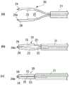
图2是第二实施方式的医疗用镊子的前端的放大立体图。2 is an enlarged perspective view of the distal end of the medical forceps according to the second embodiment.
图3是第三实施方式的医疗用镊子的前端的放大立体图。3 is an enlarged perspective view of the distal end of the medical forceps according to the third embodiment.
图4是第四实施方式的医疗用镊子的前端的放大立体图。4 is an enlarged perspective view of the distal end of the medical forceps according to the fourth embodiment.
图5的(a)~(c)是用于说明第一实施方式至第四实施方式的镊子的动作的图,图5的(a)表示夹持部打开的状态的镊子,图5的(b)表示夹持部的前端侧轻微关闭的状态的镊子,图5的(c)表示夹持部关闭的状态的镊子。(a) to (c) of FIG. 5 are diagrams for explaining the operation of the tweezers according to the first to fourth embodiments. b) shows the tweezers in a state in which the distal end side of the grip portion is slightly closed, and FIG. 5( c ) shows the tweezers in the state where the grip portion is closed.
具体实施方式Detailed ways
在下面的详细说明中,出于说明的目的,为了提供对所公开的实施方式的彻底的理解,提出了许多具体的细节。然而,显然可以在没有这些具体细节的前提下实施一个或更多的实施方式。在其它的情况下,为了简化制图,示意性地示出了众所周知的结构和装置。In the following detailed description, for the purposes of explanation, numerous specific details are set forth in order to provide a thorough understanding of the disclosed embodiments. It will be apparent, however, that one or more embodiments may be practiced without these specific details. In other instances, well-known structures and devices are schematically shown in order to simplify the drawings.
以下,参照附图对本发明的实施方式进行说明。另外,镊子整体的结构以及机构由于与日本专利公开公报特开2020-044289号中公开的镊子相同,所以省略对它们的说明。在以下的说明中,将重点放在成为本实施方式的主要部分的前端部的说明。Hereinafter, embodiments of the present invention will be described with reference to the drawings. In addition, since the structure and mechanism of the whole tweezers are the same as those of the tweezers disclosed in Japanese Unexamined Patent Publication No. 2020-044289, their descriptions are omitted. In the following description, emphasis will be placed on the description of the distal end portion, which is the main part of the present embodiment.
图1是第一实施方式的医疗用镊子的前端的放大立体图。该医疗用镊子例如用于医疗手术。如同图所示,作为第一实施方式的医疗用镊子的镊子10具备:构成一对的臂部20的颈部22以及狭缝形成部23;设置在臂部20的前端的夹持部24;以及配置在臂部20的根部的套筒30。FIG. 1 is an enlarged perspective view of the distal end of the medical forceps according to the first embodiment. The medical forceps are used for medical surgery, for example. As shown in the figure, the
该镊子10具有通过一对的颈部22相对于套筒30的内腔出入时的滑动作用而使一对的夹持部24开闭的机构。This
在一对的颈部22的前端侧设置有一对的狭缝形成部23。在狭缝形成部23的前端设置有一对的夹持部24。在各夹持部24的彼此相对的一侧设置有夹持面24a。与夹持部24开闭对应地,夹持对象物被夹持面24a接触夹持。该夹持面24a是设置在夹持部24的至少一部分上的、具有第一表面粗糙度的第一区域的一个例子。该夹持面24a具有沿轴向延伸的长方形的长平面。而且,设定颈部22的弯曲形状,使得当关闭了夹持部24时夹持面24a彼此面接触。A pair of
另外,在夹持部24与颈部22之间设置有狭缝形成部23。该狭缝形成部23具有当关闭了夹持部24时在一对的狭缝形成部23彼此之间形成狭缝的形状。In addition, a
通过该狭缝的形成,能够增大施加到夹持面24a的每单位面积的夹持力。形成的狭缝也成为用眼睛确认夹持部24时的目标。By forming this slit, the clamping force per unit area applied to the
在此,颈部22形成为具有适合弹性变形的厚度。狭缝形成部23形成为具有能够得到能向夹持部24传递夹持力的刚性的厚度。Here, the
通过粗糙面化处理,在夹持部24的各夹持面24a上形成有由不规则的隆起构成的粗糙面区域,各夹持面24a具有第一表面粗糙度。夹持部24的夹持面24a以外的部分以及臂部20的整体是与作为第一区域的夹持面24a相邻的区域的一个例子,并且是具有与第一表面粗糙度不同的表面粗糙度的第二区域的一个例子。通过镜面处理在夹持部24的夹持面24a以外的部分以及臂部20的整体形成镜面区域。By the roughening treatment, a rough surface region composed of irregular protrusions is formed on each of the holding surfaces 24 a of the holding
通过这些粗糙面以及镜面,用同图中的实线表示的、从光源LS照射的光产生用同图中的虚线表示的反射光。即,反射光在粗糙面区域发生散射。另一方面,在镜面区域,反射光向特定方向反射。其结果,在夹持面24a与其以外的部分之间产生明暗的反差。这样,镊子10在夹持面24a(第一区域)与夹持面24a以外的部分(第二区域)之间,具有在照明下能够识别各区域的边界(例如夹持面24a与夹持面24a以外的部分的边界)的明暗差。由此,通过使夹持面24a显眼,能够提高夹持部24以及夹持面24a的易辨认性。因此,能够准确地识别夹持面24a的划定区域、形状、大小、以及在处置空间中的存在位置。By these rough surfaces and mirror surfaces, the light irradiated from the light source LS indicated by the solid line in the same figure generates reflected light indicated by the dotted line in the same figure. That is, reflected light is scattered in the rough surface area. On the other hand, in the specular area, the reflected light is reflected in a specific direction. As a result, a light and dark contrast is generated between the clamping
尤其是,即使在边使臂部20在用同图中的箭头R表示的方向上向顺时针方向或逆时针方向转动、边实施处置的情况下,在夹持面24a成为背面的臂部20的转动角度以外,在夹持面24a产生明暗的反差。因此,不论臂部20的转动姿势如何,在多数场景下都能够提高夹持部24以及夹持面24a的易辨认性。In particular, even when the treatment is performed while rotating the
图2是第二实施方式的医疗用镊子的前端的放大立体图。在同图中所示的实施方式中,在夹持部24中的夹持面24a以外的侧面、端面以及背面上也设置有粗糙面区域(第一区域)。通过这样的构成,即使在根据光源LS的位置或光的照射方向导致夹持面24a隐藏的情况下、以及关闭一对的夹持部24而使夹持面24a不露出的情况下,也能够识别夹持部24。2 is an enlarged perspective view of the distal end of the medical forceps according to the second embodiment. In the embodiment shown in the same figure, rough surface regions (first regions) are also provided on side surfaces, end surfaces, and back surfaces other than the pinching
但是,如果使夹持部24的整体粗糙面化,则变得难以识别表示夹持面24a的划定区域的边界。因此,在尤其想要识别夹持面24a的情况下,如图1所示,优选的是仅使夹持部24中的夹持面24a粗糙面化。However, when the
图3是第三实施方式的医疗用镊子的前端的放大立体图。在同图所示的实施方式中,形成在夹持面24a的粗糙面是在与轴向正交的方向上隆起的粗糙面的例子。这样,在与轴向正交的方向上形成不规则的隆起,在提高镊子10的夹持面24a的易辨认性方面变得重要。即,通过使隆起与从同图的光源LS入射的光的方向相对,能够得到合适的散射。因此,形成在夹持面24a的粗糙面优选的是至少是包括朝向与轴向正交的方向的隆起的粗糙面。3 is an enlarged perspective view of the distal end of the medical forceps according to the third embodiment. In the embodiment shown in the same figure, the rough surface formed on the holding
另外,在光入射到规则性的隆起的情况下,光仅向特定方向反射。因此,在形成在夹持面24a的粗糙面包含大量规则性的隆起的情况下,夹持面24a的易辨认性的提高程度依赖于镊子10的姿势。因此优选的是,形成在夹持面24a的粗糙面包括山谷的高度以及间隔不规则的隆起。In addition, when light is incident on the regular bumps, the light is reflected only in a specific direction. Therefore, when the rough surface formed on the
图4是第四实施方式的医疗用镊子的前端的放大立体图。在同图所示的实施方式中,表示了仅在夹持部24的前端侧形成有粗糙面区域的例子。该夹持部24在如后述的图5中详述的镊子10具备在夹持对象物时夹持面24a从前端侧依次接触对象物这样的夹持机构的情况下是有用的。另外,该夹持部24在尤其想要识别与对象物最初接触的前端部分的情况下也是有用的。4 is an enlarged perspective view of the distal end of the medical forceps according to the fourth embodiment. In the embodiment shown in the same figure, an example in which the rough surface region is formed only on the distal end side of the gripping
图5的(a)~(c)是用于说明第一实施方式至第四实施方式的医疗用镊子的动作的图。图5的(a)表示夹持部打开的状态的镊子。图5的(b)表示夹持部的前端侧轻微关闭的状态的镊子。图5的(c)表示夹持部关闭着的状态的镊子。与第四实施方式所示的粗糙面区域同样地,该镊子的粗糙面区域仅形成在夹持部24的前端侧。(a)-(c) of FIG. 5 is a figure for demonstrating the operation|movement of the medical forceps of 1st to 4th embodiment. Fig. 5(a) shows the tweezers in a state in which the grip portion is opened. Fig. 5(b) shows the tweezers in a state in which the distal end side of the gripping portion is slightly closed. Fig. 5(c) shows the tweezers in a state in which the gripping portion is closed. Similar to the rough surface region shown in the fourth embodiment, the rough surface region of the tweezers is formed only on the distal end side of the gripping
如图5的(a)所示,当颈部22未收纳在套筒30的内腔中时,夹持部24彼此成为打开的状态。当从该状态使套筒30滑动将颈部22的最初的弯曲部收纳到套筒30的内腔中时,如图5的(b)所示,夹持部24的夹持面24a彼此从前端侧开始接触。此时,臂部20的前端侧(夹持部24的前端侧)成为轻微关闭的状态。另一方面,臂部20的套筒侧(夹持部24的套筒侧)成为稍稍打开的状态。As shown in FIG. 5( a ), when the
如图5的(c)所示,如果进一步使套筒30滑动将颈部22的整体收纳到套筒30的内腔中,则前端侧的弯曲部发挥弹簧的作用,夹持面24a彼此面接触。As shown in FIG. 5( c ), when the
按照这样的夹持机构,在进行牵拉提升视网膜附近的增生膜这样的细致处置的情况下,能够边抑制夹持面24a的前端侧打开、边使夹持面24a彼此面接触。因此,通过夹持面24a能够适当地夹持微小组织。According to such a clamping mechanism, in the case of performing a delicate treatment such as pulling and lifting the proliferative membrane in the vicinity of the retina, the clamping surfaces 24a can be brought into surface contact with each other while preventing the distal end side of the clamping surfaces 24a from being opened. Therefore, the fine tissue can be appropriately held by the holding
在此,在到图5的(a)所示这样的夹持对象物之前的阶段中,通过设置在夹持面24a的前端的粗糙面区域,能够识别与对象物最初接触的夹持面24a的前端。另一方面,在图5的(b)以及图5的(c)所示这样的夹持对象物的阶段中,通过设置在夹持面24a的背侧以及侧面的粗糙面区域,能够识别夹持面24a的前端。Here, the rough surface area provided at the tip end of the
出于示例和说明的目的已经给出了所述详细的说明。根据上面的教导,许多变形和改变都是可能的。所述的详细说明并非没有遗漏或者旨在限制在这里说明的主题。尽管已经通过文字以特有的结构特征和/或方法过程对所述主题进行了说明,但应当理解的是,权利要求书中所限定的主题不是必须限于所述的具体特征或者具体过程。更确切地说,将所述的具体特征和具体过程作为实施权利要求书的示例进行了说明。The detailed description has been presented for the purposes of example and description. Many variations and changes are possible in light of the above teachings. The detailed description is not exhaustive or intended to limit the subject matter described herein. Although the subject matter has been described in text with specific structural features and/or methodological processes, it is to be understood that the subject matter defined in the claims is not necessarily limited to the specific features or specific processes described. Rather, the specific features and specific procedures described are described as examples of implementing the claims.
Claims (3)
Applications Claiming Priority (2)
| Application Number | Priority Date | Filing Date | Title |
|---|---|---|---|
| JP2020162055AJP7506570B2 (en) | 2020-09-28 | 2020-09-28 | Medical Forceps |
| JP2020-162055 | 2020-09-28 |
Publications (1)
| Publication Number | Publication Date |
|---|---|
| CN114305594Atrue CN114305594A (en) | 2022-04-12 |
Family
ID=80624586
Family Applications (1)
| Application Number | Title | Priority Date | Filing Date |
|---|---|---|---|
| CN202110924114.5APendingCN114305594A (en) | 2020-09-28 | 2021-08-12 | Medical forceps |
Country Status (4)
| Country | Link |
|---|---|
| US (1) | US20220096109A1 (en) |
| JP (1) | JP7506570B2 (en) |
| CN (1) | CN114305594A (en) |
| DE (1) | DE102021210490A1 (en) |
Cited By (1)
| Publication number | Priority date | Publication date | Assignee | Title |
|---|---|---|---|---|
| RU215577U1 (en)* | 2022-10-05 | 2022-12-19 | федеральное государственное автономное учреждение "Национальный медицинский исследовательский центр "Межотраслевой научно-технический комплекс "Микрохирургия глаза" имени академика С.Н. Федорова" Министерства здравоохранения Российской Федерации | Microsurgical ophthalmic tweezers for removing artificial iris from the anterior chamber of the eye |
Citations (5)
| Publication number | Priority date | Publication date | Assignee | Title |
|---|---|---|---|---|
| GB778877A (en)* | 1955-03-28 | 1957-07-10 | Leelan Earl Witney | Improvements in or relating to forceps and the like |
| US4671283A (en)* | 1984-02-28 | 1987-06-09 | Micra Ltd. | Forceps |
| CN101516281A (en)* | 2006-08-31 | 2009-08-26 | 华沙整形外科股份有限公司 | Polymer rods for spinal applications |
| US8020909B1 (en)* | 2008-03-07 | 2011-09-20 | Lavaque Barry J | Pincers illuminating items grasped therein |
| CN106163464A (en)* | 2014-02-24 | 2016-11-23 | 诺华股份有限公司 | There is the operating theater instruments adhering to optimize boundary condition |
Family Cites Families (8)
| Publication number | Priority date | Publication date | Assignee | Title |
|---|---|---|---|---|
| US3515139A (en)* | 1966-08-29 | 1970-06-02 | Codman & Shurtleff | Atraumatic clamp |
| JP3136695U (en)* | 2007-04-27 | 2007-11-08 | 清 永井 | Electropolished stainless steel appliances for doctors |
| DE202008007775U1 (en) | 2008-06-11 | 2008-08-07 | Ovesco Endoscopy Gmbh | Medical gripping device |
| US20100057094A1 (en)* | 2008-08-27 | 2010-03-04 | Takayuki Akahoshi | IOL Forceps With Shaped Jaws |
| US9320534B2 (en) | 2012-12-13 | 2016-04-26 | Alcon Research, Ltd. | Fine membrane forceps with integral scraping feature |
| JP3215968U (en) | 2018-02-13 | 2018-04-26 | 有限会社川尻工業 | Autopsy tweezers |
| JP7013350B2 (en) | 2018-09-21 | 2022-01-31 | マニー株式会社 | Ophthalmic surgical instruments |
| JP7135969B2 (en) | 2019-03-27 | 2022-09-13 | 富士通株式会社 | Information processing method and information processing apparatus |
- 2020
- 2020-09-28JPJP2020162055Apatent/JP7506570B2/enactiveActive
- 2021
- 2021-08-03USUS17/392,872patent/US20220096109A1/ennot_activeAbandoned
- 2021-08-12CNCN202110924114.5Apatent/CN114305594A/enactivePending
- 2021-09-21DEDE102021210490.8Apatent/DE102021210490A1/enactivePending
Patent Citations (5)
| Publication number | Priority date | Publication date | Assignee | Title |
|---|---|---|---|---|
| GB778877A (en)* | 1955-03-28 | 1957-07-10 | Leelan Earl Witney | Improvements in or relating to forceps and the like |
| US4671283A (en)* | 1984-02-28 | 1987-06-09 | Micra Ltd. | Forceps |
| CN101516281A (en)* | 2006-08-31 | 2009-08-26 | 华沙整形外科股份有限公司 | Polymer rods for spinal applications |
| US8020909B1 (en)* | 2008-03-07 | 2011-09-20 | Lavaque Barry J | Pincers illuminating items grasped therein |
| CN106163464A (en)* | 2014-02-24 | 2016-11-23 | 诺华股份有限公司 | There is the operating theater instruments adhering to optimize boundary condition |
Cited By (1)
| Publication number | Priority date | Publication date | Assignee | Title |
|---|---|---|---|---|
| RU215577U1 (en)* | 2022-10-05 | 2022-12-19 | федеральное государственное автономное учреждение "Национальный медицинский исследовательский центр "Межотраслевой научно-технический комплекс "Микрохирургия глаза" имени академика С.Н. Федорова" Министерства здравоохранения Российской Федерации | Microsurgical ophthalmic tweezers for removing artificial iris from the anterior chamber of the eye |
Also Published As
| Publication number | Publication date |
|---|---|
| JP7506570B2 (en) | 2024-06-26 |
| DE102021210490A1 (en) | 2022-03-31 |
| US20220096109A1 (en) | 2022-03-31 |
| JP2022054826A (en) | 2022-04-07 |
Similar Documents
| Publication | Publication Date | Title |
|---|---|---|
| KR101840312B1 (en) | Method for presenting force sensor information using cooperative robot control and audio feedback | |
| CN106163464B (en) | Surgical instrument with adhesion-optimized edge conditions | |
| CN104837444B (en) | Fine Film Clamp with Integral Scratch Feature | |
| CN103037798B (en) | The micro-power handled for the operation of slim and frahile tissue guides cooperation control | |
| JP4207717B2 (en) | Personal authentication device | |
| US4165745A (en) | Surgical manipulator | |
| CN105809188B (en) | A kind of fungal keratitis image-recognizing method based on AMBP innovatory algorithms | |
| JPS60203245A (en) | Tweezers | |
| EP3154455B1 (en) | Oct transparent surgical instruments and methods | |
| TWI766378B (en) | Ophthalmic forceps | |
| CN114305594A (en) | Medical forceps | |
| Cheon et al. | Motorized microforceps with active motion guidance based on common-path SSOCT for epiretinal membranectomy | |
| Zhou et al. | Spotlight-based 3D instrument guidance for retinal surgery | |
| JP4995961B2 (en) | Opening / closing tool | |
| Alamdar et al. | Force and velocity based puncture detection in robot assisted retinal vein cannulation: In-vivo study | |
| US20220304563A1 (en) | Lens cleaning system and method for a surgical camera | |
| CN216256999U (en) | Endoscope lift pincers ware, endoscope head end and endoscope | |
| WO2023027095A1 (en) | Manipulation system and manipulation method | |
| Guo et al. | Deformation control of a deformable object based on visual and tactile feedback | |
| US8147512B1 (en) | Dual closing guide for a surgical instrument | |
| JP4760870B2 (en) | Personal authentication apparatus and method | |
| US12201316B2 (en) | Micro needle holder capable of cutting sutures | |
| Nambi et al. | Effect of haptic-interface virtual kinematics on the performance and preference of novice users in telemanipulated retinal surgery | |
| JPH11290341A (en) | Endoscope treatment tool holding device | |
| CN213098322U (en) | Protective sheath is cut to tissue |
Legal Events
| Date | Code | Title | Description |
|---|---|---|---|
| PB01 | Publication | ||
| PB01 | Publication | ||
| SE01 | Entry into force of request for substantive examination | ||
| SE01 | Entry into force of request for substantive examination | ||
| WD01 | Invention patent application deemed withdrawn after publication | Application publication date:20220412 | |
| WD01 | Invention patent application deemed withdrawn after publication |