CN114235020B - A Penetration Actuator Based on Shear Thickening Effect and Its Working Method - Google Patents
A Penetration Actuator Based on Shear Thickening Effect and Its Working MethodDownload PDFInfo
- Publication number
- CN114235020B CN114235020BCN202111605654.3ACN202111605654ACN114235020BCN 114235020 BCN114235020 BCN 114235020BCN 202111605654 ACN202111605654 ACN 202111605654ACN 114235020 BCN114235020 BCN 114235020B
- Authority
- CN
- China
- Prior art keywords
- feeding device
- driver
- penetration
- fixedly connected
- moving
- Prior art date
- Legal status (The legal status is an assumption and is not a legal conclusion. Google has not performed a legal analysis and makes no representation as to the accuracy of the status listed.)
- Active
Links
- 230000035515penetrationEffects0.000titleclaimsabstractdescription29
- 230000000694effectsEffects0.000titleclaimsabstractdescription16
- 230000008719thickeningEffects0.000titleclaimsabstractdescription16
- 238000000034methodMethods0.000titleclaimsdescription12
- 230000005540biological transmissionEffects0.000claimsabstractdescription27
- 239000012530fluidSubstances0.000claimsabstractdescription18
- 238000007789sealingMethods0.000claimsabstractdescription7
- 239000002245particleSubstances0.000claimsabstractdescription4
- 239000007787solidSubstances0.000claimsabstractdescription4
- 230000000149penetrating effectEffects0.000claimsdescription50
- 230000033001locomotionEffects0.000claimsdescription20
- 230000001133accelerationEffects0.000claimsdescription9
- 230000009471actionEffects0.000claimsdescription9
- 239000000463materialSubstances0.000claimsdescription7
- 230000008569processEffects0.000claimsdescription5
- 238000006073displacement reactionMethods0.000claimsdescription4
- 229910001285shape-memory alloyInorganic materials0.000claimsdescription4
- 238000009434installationMethods0.000description3
- 230000008901benefitEffects0.000description2
- 238000001514detection methodMethods0.000description2
- 238000010586diagramMethods0.000description2
- JJWKPURADFRFRB-UHFFFAOYSA-Ncarbonyl sulfideChemical compoundO=C=SJJWKPURADFRFRB-UHFFFAOYSA-N0.000description1
- 238000004146energy storageMethods0.000description1
- 238000005516engineering processMethods0.000description1
- 230000006870functionEffects0.000description1
- 229920000642polymerPolymers0.000description1
- 239000004576sandSubstances0.000description1
- 239000002689soilSubstances0.000description1
- 239000000725suspensionSubstances0.000description1
- XLYOFNOQVPJJNP-UHFFFAOYSA-NwaterSubstancesOXLYOFNOQVPJJNP-UHFFFAOYSA-N0.000description1
Images
Classifications
- G—PHYSICS
- G01—MEASURING; TESTING
- G01D—MEASURING NOT SPECIALLY ADAPTED FOR A SPECIFIC VARIABLE; ARRANGEMENTS FOR MEASURING TWO OR MORE VARIABLES NOT COVERED IN A SINGLE OTHER SUBCLASS; TARIFF METERING APPARATUS; MEASURING OR TESTING NOT OTHERWISE PROVIDED FOR
- G01D11/00—Component parts of measuring arrangements not specially adapted for a specific variable
Landscapes
- Physics & Mathematics (AREA)
- General Physics & Mathematics (AREA)
- Placing Or Removing Of Piles Or Sheet Piles, Or Accessories Thereof (AREA)
- Earth Drilling (AREA)
Abstract
Description
Translated fromChinese技术领域technical field
本发明涉及一种贯入式驱动器,具体涉及一种基于剪切增稠效应驱动的贯入式驱动器及其工作方法。The invention relates to a penetrating driver, in particular to a penetrating driver based on a shear thickening effect and a working method thereof.
背景技术Background technique
随着科学技术的不断发展,在地理环境勘察、海底探测、深空星体着陆探查等领域,都对贯入式驱动器提出了更高的要求,希望贯入式驱动器能够尽可能轻巧的同时,具备更深的探测行程。而传统的贯入式驱动器,其探测行程都受到驱动器自身特征长度的限制,探入深度有限,且体积沉重,不具备便携、轻巧的特点。因此有必要对贯入式驱动器进行研究,探索,设计能够实现相关功能的新型驱动原理以及驱动结构。With the continuous development of science and technology, higher requirements are put forward for penetrating drives in the fields of geographical environment survey, seabed exploration, and deep space star landing exploration. It is hoped that the penetrating drive can be as light as possible while having Deeper probing trips. However, the detection stroke of the traditional penetration driver is limited by the characteristic length of the driver itself, the penetration depth is limited, and the volume is heavy, which does not have the characteristics of portability and lightness. Therefore, it is necessary to study, explore, and design new driving principles and driving structures that can realize related functions.
发明内容Contents of the invention
为了满足上述需求,本发明的旨在在于提供一种体积小,重量轻,贯入探查时工作深度不受到驱动器自身特征长度影响的贯入式驱动器,具体为一种基于剪切增稠效应的贯入式驱动器,并设计了该驱动器的贯入式工作方法。In order to meet the above needs, the purpose of the present invention is to provide a penetrating driver whose working depth is not affected by the characteristic length of the driver itself during penetrating exploration, specifically a kind of penetrating driver based on the shear thickening effect. penetrating driver, and designed the penetrating working method of the driver.
为达到上述目的,本发明所采用的技术方案如下:In order to achieve the above object, the technical scheme adopted in the present invention is as follows:
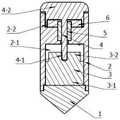
一种基于剪切增稠效应的贯入式驱动器,包括贯入端1,与贯入端1上端部两侧固定连接的驱动器外壳2,设置在驱动器外壳2内位于贯入端1上部并与驱动器外壳2固定连接的进给装置3,传动结构4设置在驱动器外壳2顶部,传动结构4的传动杆4-1间隙配合穿过驱动器外壳2中部通孔并插入进给装置顶部的进给装置运动端3-2中与进给装置运动端3-2固定连接,插入驱动器外壳2中部通孔中限制传动结构4只能产生直线运动的限位套筒5,压紧限位套筒5的密封盖板6;A penetrating driver based on the shear thickening effect, comprising a penetrating
进给装置3底部为进给装置固定端3-1;其中与进给装置固定端3-1固连,共同进行刚体运动的结构多,质量大,包括贯入端1、驱动器外壳2、限位套筒5和密封盖板6;与进给装置运动端3-2固连,共同进行刚体运动的结构少,质量轻,包括传动结构4。The bottom of the
所述进给装置3为能够完成直线位移输出的驱动装置,采用音圈电机、直线电机、气/液动执行器、超声电机、磁致伸缩材料、电致伸缩材料或形状记忆合金及其所衍生的线性执行器。The
所述的基于剪切增稠效应的贯入式驱动器的工作方法,贯入式驱动器工作初始状态,浸没入非牛顿流体介质或类非牛顿流体的固体颗粒中,开始驱动工作前,进给装置3处于最小行程状态;In the working method of the penetrating drive based on the shear thickening effect, the initial state of the penetrating drive is immersed in a non-Newtonian fluid medium or a solid particle of a non-Newtonian fluid. Before starting to drive, the
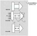
驱动步骤1:给进给装置3施加快速的控制信号,控制进给装置3快速身长,进给装置3所包含的进给装置固定端3-1,进给装置运动端3-2相互远离;在这一过程中,由于与进给装置固定端3-1所固连,共同运动的结构质量大,加速度小,故进给装置固定端3-1与其固连的结构运动速度v1小;由于与进给装置运动端3-2所固连,共同运动的结构质量小,加速度大,故进给装置运动端3-2与其固连的结构运动速度v2大;在运动过程中,与进给装置固定端3-1连接的贯入端1在运动中受到非牛顿流体介质的作用力为F1,与进给装置运动端3-2连接的传动结构4受到非牛顿流体介质的作用力为F4,由于运动速度关系有v1<v2,产生F1作用的介质剪切应力τ1大于产生F4作用的介质剪切应力τ4,由于非牛顿流体介质的粘度随着剪切速率或剪切应力的增加展现出数量级增加,所以F1远小于F4,以贯入式驱动器整体考虑,其两侧的作用力不平衡,故驱动器整体将向着F4所指向的方向即贯入式驱动器贯入端1的方向运动;Driving step 1: apply a fast control signal to the
驱动步骤2:给进给装置3施加缓慢的控制信号,控制进给装置3缓慢恢复至最小行程状态,进给装置3所包含的进给装置固定端3-1与进给装置运动端3-2的运动速度接近;在这一阶段中,由于加速度低,运动速度远低于驱动步骤1中的运动速度,贯入式驱动器的贯入端1与贯入式驱动器的传动结构4受到的外部作用力接近,贯入式驱动器所受到的介质作用力处于平衡状态,贯入式驱动器停止运动。Driving step 2: Apply a slow control signal to the
与现有技术相比,本发明具有下述优点:Compared with prior art, the present invention has following advantage:
1、驱动结构简单,不同于其他贯入式驱动器中需要复杂的储能装置,本发明中仅需进给装置3进行简单直线运动,即可完成驱动。1. The drive structure is simple, unlike other penetrating drives that require complex energy storage devices, the present invention only requires the
2、本发明所述的贯入式驱动器结构简单,质量轻巧,便于携带,特别适合于地理环境勘察、海底探测、深空星体着陆探查等极端环境下的使用。2. The penetrating driver described in the present invention has the advantages of simple structure, light weight, and portability, and is especially suitable for use in extreme environments such as geographical environment survey, seabed exploration, and deep-space star landing exploration.
3、本发明所述的贯入式驱动器,在完全浸没入介质后依靠介质的剪切增稠效应产生驱动力,能够实现的贯入式运动深度不受驱动器自身特征长度的限制,驱动行程远超一般的贯入式探查装置。3. The penetrating driver described in the present invention relies on the shear thickening effect of the medium to generate the driving force after being completely immersed in the medium. Ultra-general penetrating detection device.
附图说明Description of drawings
图1为本发明贯入式驱动器剖视图。Fig. 1 is a sectional view of the penetrating driver of the present invention.
图2为本发明贯入式驱动器驱动原理示意图。Fig. 2 is a schematic diagram of the driving principle of the penetrating driver of the present invention.
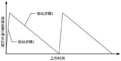
图3为本发明贯入式驱动器进给装置3位移控制示意图。Fig. 3 is a schematic diagram of the displacement control of the penetrating
具体实施方式detailed description
下面结合附图和具体实施方式对本发明作进一步详细说明。The present invention will be described in further detail below in conjunction with the accompanying drawings and specific embodiments.
如图1所示,本发明一种基于剪切增稠效应的贯入式驱动器,包括贯入端1,与贯入端1上端部两侧固定连接的驱动器外壳2,设置在驱动器外壳2内位于贯入端1上部并与驱动器外壳2固定连接的进给装置3,传动结构4设置在驱动器外壳2顶部,传动结构4的传动杆间隙配合穿过驱动器外壳2中部通孔并插入进给装置运动端3-2中与进给装置运动端3-2固定连接,插入驱动器外壳2中部通孔中限制传动结构4只能产生直线运动的限位套筒5,压紧限位套筒5的密封盖板6。As shown in Figure 1, a penetrating driver based on the shear thickening effect of the present invention includes a
如图1所示,所述的基于剪切增稠效应的贯入式驱动器,驱动结构外壳2中间的凸台形成了驱动器外壳内上部的进给装置安装仓2-1和下部的驱动器外壳导向仓2-2;进给装置3包括进给装置固定端3-1和进给装置运动端3-2;传动结构4包含传动杆4-1和传动结构输出端4-2。进给装置3安装于驱动结构外壳2中的进给装置安装仓2-1中,进给装置固定端3-1与驱动器外壳2以及贯入端1固定连接,进给装置运动端3-2与传动杆4-1固定连接;传动结构4从驱动器外壳导向仓2-2穿过驱动结构外壳2中部的通孔,通入驱动器外壳的进给装置安装仓2-1。As shown in Figure 1, in the penetrating drive based on the shear thickening effect, the boss in the middle of the
所述的基于剪切增稠效应的贯入式驱动器,其进给装置3应当选用能够完成直线位移输出的驱动装置,包括音圈电机、直线电机、气/液动执行器、超声电机、磁致伸缩材料、电致伸缩材料、形状记忆合金及其所衍生的线性执行器。For the penetrating driver based on the shear thickening effect, the
所述的基于剪切增稠效应的贯入式驱动器,进给装置3的两端分别为进给装置固定端3-1以及进给装置运动端3-2;其中与进给装置固定端3-1固连,共同进行刚体运动的结构多,质量大,包括贯入端1、、驱动器外壳2、限位套筒5和密封盖板6;与进给装置运动端3-2固连,共同进行刚体运动的结构少,质量轻,包括传动结构4。In the penetrating drive based on the shear thickening effect, the two ends of the
所述的基于剪切增稠效应的贯入式驱动器,可以工作在具有粘度随着剪切速率或剪切应力的增加展现出数量级增加的非牛顿流体或类非牛顿流体的固体颗粒中,例如高分子聚合物的浓溶液和悬浮液,高含沙水流、泥石流、地幔、沼泽,地球与宇宙星体的沙土等。The described penetrating driver based on the shear thickening effect can work in solid particles having a non-Newtonian fluid or a non-Newtonian fluid-like fluid whose viscosity increases by an order of magnitude with the increase of the shear rate or shear stress, for example Concentrated solutions and suspensions of high molecular polymers, highly sandy water flows, debris flows, mantles, swamps, sand and soil on the earth and cosmic stars, etc.
所述的基于剪切增稠效应的贯入式驱动器的工作方法,如图2和图3所示。贯入式驱动器工作初始状态,浸没入非牛顿流体介质中,开始驱动工作前,进给装置3处于最小行程状态。The working method of the penetration driver based on the shear thickening effect is shown in Fig. 2 and Fig. 3 . In the initial working state of the penetrating drive, it is immersed in a non-Newtonian fluid medium, and before starting to drive, the
驱动步骤1:给进给装置3施加快速的控制信号,控制进给装置3快速身长,进给装置3所包含的进给装置固定端3-1,进给装置运动端3-2相互远离。在这一过程中,由于与进给装置固定端3-1所固连,共同运动的结构质量大,加速度小,故进给装置固定端3-1与其固连的结构运动速度v1小;由于与进给装置运动端3-2所固连,共同运动的结构质量小,加速度大,故进给装置运动端3-2与其固连的结构运动速度v2大。在运动过程中,与进给装置固定端3-1连接的贯入端1在运动中受到非牛顿流体介质的作用力为F1,与进给装置运动端3-2连接的传动结构4受到非牛顿流体介质的作用力为F4,由于运动速度关系有v1<v2,产生F1作用的介质剪切应力τ1大于产生F4作用的介质剪切应力τ4,由于非牛顿流体介质的粘度随着剪切速率或剪切应力的增加展现出数量级增加,所以F1远小于F4,以贯入式驱动器整体考虑,其两侧的作用力不平衡,故驱动器整体将向着F4所指向的方向即贯入式驱动器贯入端1的方向运动。Driving step 1: apply a fast control signal to the
驱动步骤2:给进给装置3施加缓慢的控制信号,控制进给装置3缓慢恢复至最小行程状态,进给装置3所包含的进给装置固定端3-1与进给装置运动端3-2的运动速度接近。在这一阶段中,由于加速度低,运动速度远低于驱动步骤1中的运动速度,贯入式驱动器的贯入端1与贯入式驱动器的传动结构4受到的外部作用力接近,贯入式驱动器所受到的介质作用力处于平衡状态,贯入式驱动器停止运动。Drive step 2: apply a slow control signal to the
Claims (2)
Priority Applications (1)
| Application Number | Priority Date | Filing Date | Title |
|---|---|---|---|
| CN202111605654.3ACN114235020B (en) | 2021-12-25 | 2021-12-25 | A Penetration Actuator Based on Shear Thickening Effect and Its Working Method |
Applications Claiming Priority (1)
| Application Number | Priority Date | Filing Date | Title |
|---|---|---|---|
| CN202111605654.3ACN114235020B (en) | 2021-12-25 | 2021-12-25 | A Penetration Actuator Based on Shear Thickening Effect and Its Working Method |
Publications (2)
| Publication Number | Publication Date |
|---|---|
| CN114235020A CN114235020A (en) | 2022-03-25 |
| CN114235020Btrue CN114235020B (en) | 2022-12-09 |
Family
ID=80763039
Family Applications (1)
| Application Number | Title | Priority Date | Filing Date |
|---|---|---|---|
| CN202111605654.3AActiveCN114235020B (en) | 2021-12-25 | 2021-12-25 | A Penetration Actuator Based on Shear Thickening Effect and Its Working Method |
Country Status (1)
| Country | Link |
|---|---|
| CN (1) | CN114235020B (en) |
Family Cites Families (7)
| Publication number | Priority date | Publication date | Assignee | Title |
|---|---|---|---|---|
| US5159225A (en)* | 1991-10-18 | 1992-10-27 | Aura Systems, Inc. | Piezoelectric actuator |
| US6924585B2 (en)* | 2002-09-23 | 2005-08-02 | The Crest Group, Inc. | Sleeved ultrasonic transducer |
| US7770453B2 (en)* | 2004-03-04 | 2010-08-10 | Ludwiczak Damian R | Vibrating debris remover |
| CN103916045B (en)* | 2014-02-21 | 2015-02-25 | 西安交通大学 | Stepping type rotation driving device and method on basis of piezoelectric ceramics |
| CN107623461B (en)* | 2017-09-05 | 2018-12-18 | 西安交通大学 | A kind of shearing-type inertial piezoelectric rotary actuator and actuation method |
| CN108512457B (en)* | 2018-04-19 | 2019-10-18 | 西安交通大学 | Linear inertial piezoelectric actuator with displacement sensing function and its actuation method |
| CN108768205B (en)* | 2018-06-07 | 2019-08-13 | 西安交通大学 | The step-by-step movement actuator devices and method of two Piezoelectric Ceramics with E type track |
- 2021
- 2021-12-25CNCN202111605654.3Apatent/CN114235020B/enactiveActive
Also Published As
| Publication number | Publication date |
|---|---|
| CN114235020A (en) | 2022-03-25 |
Similar Documents
| Publication | Publication Date | Title |
|---|---|---|
| CN103023374A (en) | Inertia type piezoelectric linear motor | |
| Gouache et al. | First experimental investigation of dual-reciprocating drilling in planetary regoliths: Proposition of penetration mechanics | |
| Bai et al. | A longitudinal & longitudinal-torsional vibration actuator for rotary-percussive ultrasonic planetary drills | |
| Qiu et al. | Smart skin and actuators for morphing structures | |
| CN114235020B (en) | A Penetration Actuator Based on Shear Thickening Effect and Its Working Method | |
| KR101138932B1 (en) | Actuator using Magneto Rheological Unit and Driving Method thereof | |
| Bar-Cohen et al. | Ultrasonic/sonic drilling/coring (USDC) for planetary applications | |
| Li et al. | A Piezoelectric‐Driven Rock‐Drilling Device for Extraterrestrial Subsurface Exploration | |
| Kedzierski et al. | Microhydraulic electrowetting actuators | |
| US3365019A (en) | Seismic vibrator for marshland and submarine use | |
| CN102589925B (en) | Ultrasonic excitation impact space sampling drill | |
| LeBlanc et al. | Underwater implosion mechanics: experimental and computational overview | |
| Li et al. | Design and experimental verification of an underwater ultrasonic drill for rock exploration | |
| CN114337359B (en) | Large-displacement penetration driver capable of bidirectionally actuating based on pressure thickening effect | |
| Li et al. | A novel bionic jellyfish robot for seabed rock drilling and sampling exploration | |
| KR102143265B1 (en) | Wave energy convertor and method of extracting energy using the convertor | |
| AU2010253534B2 (en) | Apparatus employing pressure transients for transporting fluids | |
| Jones et al. | Vehicle propulsion by solid state motion | |
| US9389329B2 (en) | Acoustic source with piezoelectric actuator array and stroke amplification for broad frequency range acoustic output | |
| Badescu et al. | Auto-Gopher-II: a wireline rotary-hammer ultrasonic drill that operates autonomously | |
| 刘毅 et al. | Present status and prospect of tamping device exciting technology | |
| Badescu et al. | Ultrasonic/Sonic Driller/Corer as a hammer-rotary drill | |
| Aleksandrova et al. | Calculation of pipe movement with soil plug under longitudinal impact | |
| Matsuoka | Variable inertia damper using a flywheel filled by Mr Fluid | |
| Ukida et al. | A small water flow control valve using particle excitation by PZT vibrator |
Legal Events
| Date | Code | Title | Description |
|---|---|---|---|
| PB01 | Publication | ||
| PB01 | Publication | ||
| SE01 | Entry into force of request for substantive examination | ||
| SE01 | Entry into force of request for substantive examination | ||
| GR01 | Patent grant | ||
| GR01 | Patent grant |